NUREG-0800 U.S. NUCLEAR REGULATORY … which is “field run ... evaluation of the applicable...
28
Draft Revision 3 – June 2013 USNRC STANDARD REVIEW PLAN This Standard Review Plan (SRP), NUREG-0800, has been prepared to establish criteria that the U.S. Nuclear Regulatory Commission (NRC) staff responsible for the review of applications to construct and operate nuclear power plants intends to use in evaluating whether an applicant/licensee meets the NRC regulations. The SRP is not a substitute for the NRC regulations, and compliance with it is not required. However, an applicant is required to identify differences between the design features, analytical techniques, and procedural measures proposed for its facility and the SRP acceptance criteria and evaluate how the proposed alternatives to the SRP acceptance criteria provide an acceptable method of complying with the NRC regulations. The SRP sections are numbered in accordance with corresponding sections in Regulatory Guide (RG) 1.70, "Standard Format and Content of Safety Analysis Reports for Nuclear Power Plants (LWR Edition)." Not all sections of RG 1.70 have a corresponding review plan section. The SRP sections applicable to a combined license application for a new light-water reactor (LWR) are based on RG 1.206, "Combined License Applications for Nuclear Power Plants (LWR Edition)." These documents are made available to the public as part of the NRC policy to inform the nuclear industry and the general public of regulatory procedures and policies. Individual sections of NUREG-0800 will be revised periodically, as appropriate, to accommodate comments and to reflect new information and experience. Comments may be submitted electronically by email to [email protected] . Requests for single copies of SRP sections (which may be reproduced) should be made to the U.S. Nuclear Regulatory Commission, Washington, DC 20555, Attention: Reproduction and Distribution Services Section, or by fax to (301) 415-2289; or by email to [email protected] . Electronic copies of this section are available through the NRC public Web site at http://www.nrc.gov/reading-rm/doc-collections/nuregs/staff/sr0800/ , or in the NRC Agencywide Documents Access and Management System (ADAMS), at http://www.nrc.gov/reading-rm/adams.html , , under Accession # ML12334A360. NUREG-0800 U.S. NUCLEAR REGULATORY COMMISSION STANDARD REVIEW PLAN 3.9.3 ASME CODE CLASS 1, 2, AND 3 COMPONENTS AND COMPONENT SUPPORTS, AND CORE SUPPORT STRUCTURES REVIEW RESPONSIBILITIES Primary - Organization responsible for mechanical engineering reviews Secondary - None I. AREAS OF REVIEW This Standard Review Plan (SRP) section addresses the information presented in the applicant's Safety Analysis Report (SAR) concerning the structural integrity of pressure-retaining components, their supports, and core support structures which are designed in accordance with the rules of the American Society of Mechanical Engineers (ASME) Boiler and Pressure Vessel Code, (hereafter, referred to as “Code”) Section III, Division 1 and Title 10 of the Code of Federal Regulations (10 CFR) Part 50, Appendix A, General Design Criteria (GDC) 1, 2, 4, 14, and 15. The specific areas of review are as follows: 1. Loading Combinations, System Operating Transients, and Stress Limits. The design and service loading combinations (e.g., design and service loads, including system operating
Transcript of NUREG-0800 U.S. NUCLEAR REGULATORY … which is “field run ... evaluation of the applicable...
Draft Revision 3 – June 2013
USNRC STANDARD REVIEW PLAN
This Standard Review Plan (SRP), NUREG-0800, has been prepared to establish criteria that the U.S. Nuclear Regulatory Commission (NRC) staff responsible for the review of applications to construct and operate nuclear power plants intends to use in evaluating whether an applicant/licensee meets the NRC regulations. The SRP is not a substitute for the NRC regulations, and compliance with it is not required. However, an applicant is required to identify differences between the design features, analytical techniques, and procedural measures proposed for its facility and the SRP acceptance criteria and evaluate how the proposed alternatives to the SRP acceptance criteria provide an acceptable method of complying with the NRC regulations. The SRP sections are numbered in accordance with corresponding sections in Regulatory Guide (RG) 1.70, "Standard Format and Content of Safety Analysis Reports for Nuclear Power Plants (LWR Edition)." Not all sections of RG 1.70 have a corresponding review plan section. The SRP sections applicable to a combined license application for a new light-water reactor (LWR) are based on RG 1.206, "Combined License Applications for Nuclear Power Plants (LWR Edition)." These documents are made available to the public as part of the NRC policy to inform the nuclear industry and the general public of regulatory procedures and policies. Individual sections of NUREG-0800 will be revised periodically, as appropriate, to accommodate comments and to reflect new information and experience. Comments may be submitted electronically by email to [email protected].
Requests for single copies of SRP sections (which may be reproduced) should be made to the U.S. Nuclear Regulatory Commission, Washington, DC 20555, Attention: Reproduction and Distribution Services Section, or by fax to (301) 415-2289; or by email to [email protected]. Electronic copies of this section are available through the NRC public Web site at http://www.nrc.gov/reading-rm/doc-collections/nuregs/staff/sr0800/, or in the NRC Agencywide Documents Access and Management System (ADAMS), at http://www.nrc.gov/reading-rm/adams.html, , under Accession # ML12334A360.
NUREG-0800
U.S. NUCLEAR REGULATORY COMMISSION
STANDARD REVIEW PLAN 3.9.3 ASME CODE CLASS 1, 2, AND 3 COMPONENTS AND COMPONENT
SUPPORTS, AND CORE SUPPORT STRUCTURES REVIEW RESPONSIBILITIES Primary - Organization responsible for mechanical engineering reviews
Secondary - None
I. AREAS OF REVIEW
This Standard Review Plan (SRP) section addresses the information presented in the applicant's Safety Analysis Report (SAR) concerning the structural integrity of pressure-retaining components, their supports, and core support structures which are designed in accordance with the rules of the American Society of Mechanical Engineers (ASME) Boiler and Pressure Vessel Code, (hereafter, referred to as “Code”) Section III, Division 1 and Title 10 of the Code of Federal Regulations (10 CFR) Part 50, Appendix A, General Design Criteria (GDC) 1, 2, 4, 14, and 15.
The specific areas of review are as follows:
1. Loading Combinations, System Operating Transients, and Stress Limits. The design and service loading combinations (e.g., design and service loads, including system operating
3.9.3 -2 Draft Revision 3 –June 2013
transients, in combination with loads resulting from postulated seismic and other events) specified for Code constructed items designated as Code Class 1, 2, 3 (including Class 1, 2, and 3 component support structures) and core support structures are reviewed to determine that appropriate design and service limits have been designated for all loading combinations. The reviewer ascertains that the design and service stress limits and deformation criteria comply with the applicable limits specified in the Code and Appendix A to this SRP section. Service stress limits which allow inelastic deformation of Code Class 1, 2, and 3 components, component supports, and core support structures are evaluated as are the justifications for the proposed design procedures. Piping which is “field run” should be included. Internal parts of components, such as valve discs and seats and pump shafting, subjected to dynamic loading during operation of the component should also be included.
2. Design and Installation of Pressure Relief Devices. The design and installation criteria
applicable to the mounting of pressure relief devices (safety valves and relief valves) for the overpressure protection of Code Class 1, 2 and 3 components. The review includes evaluation of the applicable loading combinations and stress criteria. The design extends to consideration of the means provided to accommodate the rapidly applied reaction force that occur when a safety valve or relief valve opens, and the transient fluid-induced loads applied to the piping downstream of a safety or relief valve in a closed discharge piping system. The dynamic structural response due to boiling water reactor (BWR) safety relief valve discharge into the suppression pool is also considered. The design of safety and relief valve systems with respect to the load combinations postulated for the safety or relief valves, upstream piping or header, downstream or vent piping, system supports, and BWR suppression pool discharge devices such as ramsheads and quenchers.
The load combinations should include the most severe combination of the applicable loads due to internal fluid weight, momentum and pressure, dead weight of valves and piping, thermal load under heatup, steady state and transient valve operation, reaction forces when valves are discharging (thrust, bending, and torsion), seismic forces, and dynamic forces due to BWR safety relief valve discharge into the suppression pool as applicable. The reaction loads due to discharge of loop seal water slugs and subcooled or saturated liquid under transient or accident conditions shall also be included as valve discharge loads.
The structural response of the piping and support system with particular attention to the dynamic or time-history analyses employed in evaluating the appropriate support and restraint stiffness effects under dynamic loadings when valves are discharging. If the use of hydraulic snubbers is proposed, the snubber performance characteristics are reviewed to ensure that their effects have been considered in the analyses under steady state valve operation and repetitive load applications caused by cyclic valve opening and closing during the course of a pressure transient.
3. Component Supports. The information submitted by the applicant includes an
evaluation of Code Class 1, 2, and 3 components supports. An assessment of design and structural integrity of the supports. The review addresses three types of supports: plate and shell, linear, component standard types. All the component supports of these three types are covered in this SRP section. Although classified as component standard supports, snubbers require special consideration due to their unique function.
3.9.3 -3 Draft Revision 3 – June 2013
Snubbers provide no load path or force transmission during normal plant operations but function as rigid supports when subjected to dynamic transient loads. Component supports are those metal supports which are designed to transmit loads from the pressure-retaining boundary of the component to the building structure. The methods of analysis for calculating the responses of the reactor coolant pressure boundary (RCPB) supports resulting from the combination of loss-of-coolant accident (LOCA) and safe shutdown earthquake (SSE) events are reviewed in SRP Sections 3.6.2 and 3.9.2.
1 Inspections, Tests, Analyses, and Acceptance Criteria (ITAAC). For design
certification (DC) and combined license (COL) reviews, the staff reviews the applicant's proposed ITAAC associated with the structures, systems, and components (SSCs) related to this SRP section in accordance with SRP Section 14.3, "Inspections, Tests, Analyses, and Acceptance Criteria." The staff recognizes that the review of ITAAC cannot be completed until after the rest of this portion of the application has been reviewed against acceptance criteria contained in this SRP section. Furthermore, the staff reviews the ITAAC to ensure that all SSCs in this area of review are identified and addressed as appropriate in accordance with SRP Section 14.3.
2 COL Action Items and Certification Requirements and Restrictions. For a DC application, the review will also address COL action items and requirements and restrictions (e.g., interface requirements and site parameters).
For a COL application referencing a DC, a COL applicant must address COL action items (referred to as COL license information in certain DCs) included in the referenced DC. Additionally, a COL applicant must address requirements and restrictions (e.g., interface requirements and site parameters) included in the referenced DC.
Review Interfaces Other SRP sections interface with this section as follows: 1. Evaluation of the functionality criteria of pumps and valves and the design criteria for
pressure-relieving devices, which may have an active function during and after a faulted plant condition, against the requirements related to component functionality assurance and seismic qualification programs is performed under SRP Section 3.10.
2. Verification that the number and size of valves specified for the steam and feedwater
systems have adequate pressure-relieving capacity is performed under SRP Section 10.3.
3. Verification that the number and size of valves specified for the RCPB have adequate
pressure-relieving capacity is performed under SRP Section 5.2.2.
4. Review of the design of systems and components that interface with the reactor coolant system (RCS) with regard to intersystem loss-of-coolant accidents (ISLOCA) is performed under SRP Section 3.12.
3.9.3 -4 Draft Revision 3 – June 2013
5. Verification that the applicant has identified and addressed piping connected to the RCS that is subject to thermally stratified flow, thermal striping, and/or thermal cyclic effects, for residual heat removal and emergency core cooling systems is performed under SRP Sections 5.4.7 and 6.3.
6. Review of programs for ensuring bolting and threaded fastener adequacy and integrity is
performed under SRP Section 3.13.
The U.S. Nuclear Regulatory Commission (NRC) staff review of the applicant’s provisions for the functional qualification and operational readiness of pumps, valves, and snubbers is performed under SRP Section 3.9.6.
7. The specific acceptance criteria and review procedures are contained in that referenced SRP section.
8. Review of stiff pipe clamp designs described in Generic Issue (GI)-89 is performed under SRP Section 3.12.
II. ACCEPTANCE CRITERIA Requirements Acceptance criteria are based on meeting the relevant requirements of the following Commission regulations:
1. 10 CFR 50.55a and 10 CFR Part 50, Appendix A, GDC 1 as they relate to structures and components being designed, fabricated, erected, and tested to quality standards commensurate with the importance of the safety functions to be performed.
2. GDC 2 and 10 CFR Part 50, Appendix S, as they relate to structures and components
important to safety being designed to withstand the effects of earthquakes without loss of capability to perform their safety functions.
3. GDC 4 as it relates to structures and components important to safety being designed to
accommodate the effects of and to be compatible with the environmental conditions associated with normal operation, maintenance, testing, and postulated accidents, including lost-of-coolant accidents.
4. GDC 14 as it relates to the RCPB being designed, fabricated, erected, and tested so as to
have an extremely low probability of abnormal leakage, of rapidly propagating failure, and of gross rupture.
5. GDC 15 as it relates to the RCS and associated auxiliary, control and protection systems
being designed with sufficient margin to assure that the design conditions of the RCPB are not exceeded during any condition of normal operation, including anticipated operational occurrences.
6. 10 CFR Part 52 requirements that the components and component supports, and core
support structures will be designed and built in accordance with the certified design.
3.9.3 -5 Draft Revision 3 – June 2013
7. 10 CFR 52.47(b)(1), which requires that a DC application contain the proposed ITAAC
that are necessary and sufficient to provide reasonable assurance that, if the inspections, tests, and analyses are performed and the acceptance criteria met, a plant that incorporates the design certification is built and will operate in accordance with the DC, the provisions of the Atomic Energy Act, and the NRC regulations.
8. 8.10 CFR 52.80(a), which requires that a COL application contain the proposed
inspections, tests, and analyses, including those applicable to emergency planning, that the licensee shall perform, and the acceptance criteria that are necessary and sufficient to provide reasonable assurance that, if the inspections, tests, and analyses are performed and the acceptance criteria met, the facility has been constructed and will operate in conformity with the COL, the provisions of the Atomic Energy Act, and the NRC regulations.
SRP Acceptance Criteria
Specific SRP acceptance criteria acceptable to meet the relevant requirements of the NRC regulations identified above are as follows for the review described in this SRP section. The SRP is not a substitute for the NRC regulations, and compliance with it is not required. However, an applicant is required to identify differences between the design features, analytical techniques, and procedural measures proposed for its facility and the SRP acceptance criteria and evaluate how the proposed alternatives to the SRP acceptance criteria provide acceptable methods of compliance with the NRC regulations.
1. Loading Combinations, System Operating Transients, and Stress Limits. The design and service loading combinations, including system operating transients, and the associated design and service stress limits considered for each component and its supports should be sufficiently defined to provide the basis for design of Code Class 1, 2, and 3 components and component supports, and core support structures for all conditions.
The acceptability of the combination of design and service loadings (including system operating transients), applicable to the design of Class 1, 2, and 3 components and component supports, and core support structures, and of the designation of the appropriate design or service stress limit for each loading combination, is judged by comparison with positions stated in Appendix A, and with appropriate standards acceptable to the staff, developed by professional societies and standards organizations.
The design criteria for internal parts of components such as valve discs, seats, and pump shafting should comply with applicable Code or Code Case criteria. In those instances where no Code criteria exist, the design criteria are acceptable if they ensure the structural integrity of the part such that no safety-related functions are impaired.
3.9.3 -6 Draft Revision 3 – June 2013
2. Design and Installation of Pressure Relief Devices. The applicant should use design criteria for pressure relief installations specified in Appendix O, ASME Code, Section III, Division 1, "Rules for the Design of Safety Valve Installations.” In addition, the following criteria are applicable: A. Where more than one valve is installed on the same pipe run, the sequence of
valve openings to be assumed in analyzing for the stress at any piping location should be that sequence which is estimated to induce the maximum instantaneous value of stress at that location.
B. Stresses should be evaluated, and applicable stress limits should be satisfied for
all components of the pipe run and connecting systems and the pressure relief valve station, including supports and all connecting welds between these components.
C. In meeting the stress limit requirements, the contribution from the reaction force and the moments resulting from that force should include the effects of a Dynamic Load Factor (DLF) or should use the maximum instantaneous values of forces and moments for that location as determined by the dynamic hydraulic/structural system analysis. This requirement should be satisfied in demonstrating satisfaction of all design limits at all locations of the pipe run and the pressure relief valve for Class 1, 2, and 3 piping. A DLF of 2.0 may be used in lieu of a dynamic analysis to determine the DLF.
The SAR should also include a description of the calculational procedures, computer programs, and other methods to be used in the analysis. The analysis should include the time history or equivalent effects of changes of momentum due to fluid flow changes of direction. The fluid states considered should include postulated water slugs where water seals are used and subcooled or saturated liquid if such fluid can be discharged under postulated transient or accident conditions. Applicants for plants utilizing suppression pools should also consider the applicable pool dynamic loads on the safety relief valve system. Stress computations and stress limits must be in accord with applicable rules of the Code.
3. Component Supports. The component support designs should provide adequate margins of safety under all combinations of loadings. The combination of loadings (including system operating transients) considered for each component support within a system, including the designation of the appropriate service stress limit for each loading combination should meet the criteria in Appendix A, Regulatory Guides (RG) 1.124 and RG 1.130 and Subsection NF of the Code.
A. Component supports of active pumps and valves should be considered in context with the other features of the functionality assurance and seismic qualification program as presented in SRP Section 3.10. If the component support deformation can be expected to affect the operational readiness requirements of the supported component, then deformation limits should also be specified. Such deformation limits should be compatible with the operational readiness requirements of the supported components. These deformation limits should be incorporated into the functionality assurance and seismic qualification program.
3.9.3 -7 Draft Revision 3 – June 2013
In establishing allowable equipment deformations, the possible movements of the support base structures must be taken into account.
B. Criteria for snubber functionality assurance should contain the following elements:
(i) Structural Analysis and Systems Evaluation. Systems and
components which utilize snubbers as shock and vibration arresters should be analyzed to ascertain the interaction of such devices with the systems and components to which they are attached. Snubbers may be used as shock and vibration arresters and in some instances as dual purpose snubbers, and when so used fatigue strength should be considered. Important factors in the fatigue evaluation include:
(1) Unsupported system component movement or amplitude,
(2) Force imparted to snubber and corresponding reaction on system or component due to restricting motion (damped amplitude),
(3) Vibration frequency or number of load cycles, and
(4) Verification of system or component and snubber fatigue strength. Snubbers used as shock arresters need not undergo a fatigue evaluation if it can be demonstrated that:
(a) The number of load cycles which the snubber will experience during normal plant operating conditions is small (<2500) or
(b) Motion during normal plant operating conditions does not exceed snubber dead band.
Snubbers utilized in systems or components which may experience high thermal growth rates, either during normal operating conditions or as a result of anticipated transients, should be checked to ensure that such thermal growth rates do not exceed the snubber lock-up velocity.
(ii) Characterization of Mechanical Properties. An important aspect of the structural analysis is realistic characterization of snubber mechanical properties (i.e., spring rates) in the analytical model. Since the "effective" stiffness of a snubber is generally greater than that for the snubber support assembly (i.e., the snubber plus clamp, transition tube extension, back-up support structure, etc.) the snubber response characteristics may be "washed out" by the added flexibility in the support structure. The combined effective stiffness of the snubber and support assembly should therefore be considered in evaluating the structural response of the system or component.
Snubber spring rate should be determined independent of clearance/lost
3.9.3 -8 Draft Revision 3 – June 2013
motion, activation level, or release rate. The stiffness should be based on structural and hydraulic compliance, and the effects of temperature should be considered. The snubber end fitting clearance, mismatch of end fitting clearances, mismatch of activation and release rates, and lost motion should be minimized and should be considered when calculating snubber reaction loads and stress which are based on a linear analysis of the system or component. This is especially important in multiple snubber applications where mismatch of end fitting clearance has a greater effect on the load sharing of these snubbers than does the mismatch of activation level or release rate. Equal load sharing of multiple snubber supports should not be assumed if mismatch in end fitting clearance exists.
(iii) Design Specifications. The required structural and mechanical
performance of snubbers is determined from the applicant's structural analysis described in Subsections II.3.B(i) and (ii). The snubber Design Specification is the instrument provided by the purchaser to the supplier to ensure that the requirements are met. The Design Specification should contain:
(1) The general functional requirements,
(2) Operating environment,
(3) Applicable codes and standards,
(4) Materials of construction and standards for hydraulic fluids and lubricants,
(5) Environmental, structural, and performance design verification tests, including the required dynamic qualification, testing and extrapolation methods supporting qualification of large bore hydraulic snubbers with rated load capacities of 50 Kips or more as recommended in NUREG/CR-5416.
(6) Production unit functional verification tests and certification,
(7) Packaging, shipping, handling, and storage requirements, and
(8) Description of provisions for attachments and installation.
In addition, the procurement program should include provisions for the snubber manufacturer to submit quality assurance and assembly quality control procedures for review and acceptance by the purchaser.
(iv) Use of Additional Snubbers. Snubbers could in some instances be installed during or after plant construction. These snubbers may not have been included in the design analysis. This could occur as a result of unanticipated piping vibration, as discussed in SRP Section 3.9.2, or interference problems during construction. The effects of such snubbers
3.9.3 -9 Draft Revision 3 – June 2013
should be fully evaluated and documented to demonstrate that normal plant operations and safety are not diminished.
(v) Related Criteria for Snubber Functionality. SRP Section 3.9.3 addresses
component support design, structural analysis, systems evaluation, material characteristics, design specifications, and use of additional snubbers during plant construction. As reviewed using SRP Section 3.9.6, the functional qualification of snubbers is performed in accordance with Section (QDR), “Qualification of Dynamic Restraints,” in ASME Standard (QME)-1-2007, “Qualification of Active Mechanical Equipment Used in Nuclear Power Plants,” as accepted in Revision 3 to RG 1.100 (September 2009), “Seismic Qualification of Electrical and Active Mechanical Equipment and Functional Qualification of Active Mechanical Equipment for Nuclear Power Plants.” The operational readiness of snubbers is verified in accordance with the preoperational examination and testing and inservice examination and testing provisions specified in Subsection ISTD, “Preservice and Inservice Examination and Testing of Dynamic Restraints (Snubbers) in Light-Water Reactor Nuclear Power Plants,” of the ASME Code for Operation and Maintenance of Nuclear Power Plants as incorporated by reference in 10 CFR 50.55a.
Technical Rationale
The technical rationale for application of these acceptance criteria to the areas of review addressed by this SRP section is discussed in the following paragraphs:
1. 10 CFR 50.55a requires, in part, that components and structures be designed, fabricated, constructed, tested, and inspected to quality standards commensurate with the importance of the safety function to be performed. Quality Group A, B, and C components must meet specific provisions of the Code.
SRP Section 3.9.3 provides guidance for the staff's review of loading conditions, stresses, and stress limits for the subject components and structures. Loading conditions and stress limits are described in Appendix A, of this SRP section and Subsection NF of the Code. Stresses, stress limits, and loading combinations are specified in these documents that are expected to approximate the conditions that can be expected during the life of the plant. SRP Section 3.9.3 also provides guidance for the staff's review of interfacing issues such as design specifications, mechanical properties, and testing, as appropriate. SRP Section 3.9.3 provides related guidance on component supports as well as the installation of pressure relief devices. The guidance cites the provisions of the Code. This guidance is designed to comply with 10 CFR 50.55a.
Meeting the requirements of 10 CFR 50.55a provides reasonable assurance that components and structures important to safety are capable of performing their intended functions.
2. GDC 1 requires, in part, that components and structures important to safety be designed, fabricated, erected, and tested to quality standards commensurate with the importance of the safety functions to be performed.
3.9.3 -10 Draft Revision 3 – June 2013
SRP Section 3.9.3 provides guidance for the staff's review of loading conditions, stresses, and stress limits for the subject components and structures which are important to safety. Loading conditions, stresses, and stress limits are described in Appendix A of this SRP section and Subsection NF of the Code. Stress limits and loading combinations are specified in these documents that are appropriate to the conditions that can be expected during the life of the plant. SRP Section 3.9.3 also provides guidance for the staff's review of interfacing issues such as design specifications, mechanical properties, and testing, as appropriate. SRP Section 3.9.3 provides related guidance on component supports as well as the installation of pressure relief devices. The guidance cites the provisions of the Code to compute stresses and stress limits. This guidance is designed to comply with GDC 1. Meeting the requirements of GDC 1 provides reasonable assurance that components and structures important to safety are capable of performing their intended functions.
3. GDC 2 requires, in part, that components and structures important to safety be designed to withstand the effects of natural phenomena such as earthquakes, tornadoes, hurricanes, floods, tsunami and seiches without loss of capability to perform their safety functions. The design bases for these components and structures shall reflect, among other things, appropriate combinations of the effects of normal and accident conditions with the effects of the natural phenomena.
SRP Section 3.9.3 provides guidance for the staff's review of loading combinations, stresses and stress limits for the subject components and structures which are important to safety. These loading combinations include consideration of the effects of expected natural phenomena combined with the appropriate effects of normal and accident conditions. The stresses and stress limits (computed in accordance with the provisions of the Code) are evaluated for acceptance by the staff, to ensure that equipment is designed to withstand these conditions without loss of capability to perform their intended functions. This guidance is designed to comply with GDC 2.
Meeting the requirements of GDC 2 provides reasonable assurance that components and structures important to safety are capable of performing their intended safety functions.
4. GDC 4 requires, in part, that the nuclear power plant structures and components important to safety be designed to accommodate the effects of, and to be compatible with the environmental conditions associated with normal operation, maintenance, testing, and postulated accidents, including LOCA.
SRP Section 3.9.3 provides guidance for the staff's review of the subject components and structures which are important to safety. This guidance includes consideration of loading effects and the resulting stresses (computed in accordance with the Code) associated with normal operation, maintenance, testing, and postulated accidents, including LOCA. This guidance is designed to comply with GDC 4.
Meeting the requirements of GDC 4 provides reasonable assurance that components and structures important to safety are capable of performing their intended safety functions.
3.9.3 -11 Draft Revision 3 – June 2013
5. GDC 14 requires that the RCPB be designed, fabricated, erected, and tested so as to have an extremely low probability of abnormal leakage, of rapidly propagating failure, and of gross rupture.
SRP Section 3.9.3 provides guidance for the staff's review of Code Class 1 components and component supports, including core support structures. This guidance cites the requirements of the Code to compute stresses and stress limits that are based on the loads and load combinations described in the SRP section. Meeting these requirements provides additional assurance that components that are part of the RCPB will be designed so as to have an extremely low probability of abnormal leakage, rapidly propagating failure, and gross rupture. This guidance is designed to be in accordance with GDC 14. Meeting these requirements provides reasonable assurance that components that are part of the RCPB are capable of performing their intended safety functions and prevent the spread of radioactive materials.
6. GDC 15 requires that the RCS and associated auxiliary, control, and protection
systems be designed with sufficient margin to assure that the design conditions of the RCPB are not exceeded during any condition of normal operation, including anticipated operational occurrences.
SRP Section 3.9.3 provides guidance for the staff's review of Code Class 1 components and component supports, including core support structures. This guidance cites the requirements of the Code to compute stresses and stress limits that are based on the loads and load combinations described in the SRP section. Meeting these requirements provides additional assurance that components that are part of the RCS are designed with sufficient margin to ensure that the design conditions of the RCPB are not exceeded during any condition of normal operation, including anticipated operational occurrences. This guidance is designed to be in accordance with GDC 15.
Meeting these requirements provides reasonable assurance that the RCPB is capable of performing its intended safety function and prevents the spread of radioactive materials.
III. REVIEW PROCEDURES
The reviewer will select material from the procedures described below, as may be appropriate for a particular case.
These review procedures are based on the identified SRP acceptance criteria. For deviations from these acceptance criteria, the staff should review the applicant’s evaluation of how the proposed alternatives provide an acceptable method of complying with the relevant NRC requirements identified in Subsection II.
1. Loading Combinations, System Operating Transient, and Stress Limits. The objectives in reviewing the loading combinations and stress limits employed by the applicant in the design of Code Class 1, 2, and 3 components and component supports, and core support structures are to confirm that the appropriate postulated events have been included, that the loading combinations (including system operating transients) and the designation of design and service stress limits are appropriate. For plants designed to the requirements in 10 CFR Part 50, the reviewer determines at the CP stage that the objectives have been
3.9.3 -12 Draft Revision 3 – June 2013
addressed and are being implemented in the design by obtaining a commitment from the applicant that specific design criteria will be utilized. At the OL stage, the reviewer verifies, by checking selected Code required Design Documents such as Design Reports, Load Capacity Data Sheets, and related material, that the design criteria have been utilized and that components have been designed to meet the objectives. For reviews of design certification and COL applications under 10 CFR Part 52, the reviewer verifies that the objectives have been implemented in the design by checking selected Code required Design Documents such as Design Reports, Load Capacity Data Sheets, and related material, and verifying that the design criteria have been utilized and that components have been designed to meet the objectives. To ensure that these objectives are met, the review is performed as follows:
A. The applicant's proposed design and service loadings, and combinations thereof,
are reviewed for completeness and for appropriate designation of corresponding design and service stress limits.
B. The combination of design and service loadings, including procedures for combination, proposed by the applicant for each Code-constructed item, are reviewed to determine if they are adequate. This aspect of the review is made by comparison with the loading combinations and procedures for combination set forth in Appendix A. Deviations from the position are evaluated on a case-by-case basis by questions addressed to the applicant to determine the rationale and justification for exceptions. A final determination is based on engineering judgment and agency experience with prior applications.
C. The design and service stress limits selected by the applicant for each set of design and service loading combinations are reviewed to determine if they meet those specified in Appendix A. The criteria to ensure piping component functional capability are reviewed to determine their adequacy in meeting the objectives set forth in Appendix A. Deviations from the position may be permitted provided justification is presented by the applicant. The acceptability determination is based on considerations of adequate margins of safety.
In SECY-93-087, “Policy, Technical, and Licensing Issues Pertaining to Evolutionary and Advanced Light-Water Reactor (ALWR) Designs,” dated April 2, 1993, the staff discussed eliminating the operating-basis earthquake (OBE) from the design bases when the OBE is established at less than or equal to one third of the safe-shutdown earthquake (SSE). In the associated Staff Requirements Memorandum (SRM) dated July 21, 1993, the Commission approved the staff’s recommendations associated with eliminating the OBE from the design bases.
Appendix S to 10 CFR Part 50, “Earthquake Engineering Criteria for Nuclear Power Plants,” first issued in 1996 and revised in 2007, implements Commission policy related to the use of OBE ground motion for applications submitted after January 10, 1997. If the OBE is defined as greater than one-third of the SSE, paragraph IV.(a)(2) requires analysis and design to demonstrate that SSCs remain functional and within applicable stress, strain, and deformation limits. Loads from the OBE, therefore, would be included in the design analyses for seismic
3.9.3 -13 Draft Revision 3 – June 2013
Category I components. If the OBE is defined as one-third or less of the SSE, explicit response or design analyses are not required.
2. Design and Installation of Pressure Relief Devices. The objective of the review of the design and installation of pressure relief devices is to ensure the integrity of the pressure relieving devices and associated piping during the functioning of one or more of the relief devices. For a CP review, it is determined if there is reasonable assurance that the final design will meet this objective. At the OL stage, the final design is reviewed to determine that the objective has been met.
The review is performed as follows:
A. The design of the pressure retaining boundary of the device is reviewed by comparison with Appendix O of the Code, “Rules for the Design of Safety Valve Installations” and the additional acceptance criteria in Subsection II.2 in this SRP section. Allowable stress limits are compared with those in the Code for the appropriate class of construction. Deviations are identified and the applicant is requested to provide justification. Stress limits and loading combinations are in the subsections entitled “Loading Combinations, System Operating Transients, and Stress Limits” (Subsections II.1 and III.1) in this SRP section.
B. The design of the installation is reviewed for structural adequacy to withstand the dynamic effects of relief valve operation. The applicant should include and discuss: reaction force, valve opening sequence, valve opening time, method of analysis, and magnitude of a dynamic load factor (if used). In reaching an acceptance determination, the reviewer compares the submission with the criteria in Subsection II.2 of this SRP section.
Where deviations occur, they are identified and the justification is evaluated. Valve opening sequence effects should include the worst-case load combination and forcing functions should be justified with valve opening time data. The review will consider comparisons with prior acceptable designs tested in operating plants.
3. Component Supports. The objective in the review of component supports is to determine that adequate attention has been given the various aspects of design and analysis, so that there is reasonable assurance of structural integrity of supports and of operational readiness of active components that interact with component supports.
The reviewer verifies that the applicant's SAR contains discussions and commitments to develop and utilize a snubber operational readiness program containing the elements specified in paragraphs (i) through (v) of Subsection II.3.B of this SRP section.
The structural integrity of the three types of component supports described in Subsection I.3 of this SRP section are reviewed against the criteria and guidelines of Subsection II.3 of this SRP section.
4. For review of a DC application, the reviewer should follow the above procedures to verify that the design, including requirements and restrictions (e.g., interface requirements and site parameters), set forth in the Final Safety Analysis Report (FSAR) meets the
3.9.3 -14 Draft Revision 3 – June 2013
acceptance criteria. DCs have referred to the FSAR as the design control document (DCD). The reviewer should also consider the appropriateness of identified COL action items. The reviewer may identify additional COL action items; however, to ensure these COL action items are addressed during a COL application, they should be added to the DC FSAR.
For review of a COL application, the scope of the review is dependent on whether the COL applicant references a DC, an early site permit (ESP) or other NRC approvals (e.g., manufacturing license, site suitability report or topical report).
For review of both DC and COL applications, SRP Section 14.3 should be followed for the review of ITAAC. The review of ITAAC cannot be completed until after the completion of this section. IV. EVALUATION FINDINGS The reviewer verifies that the applicant has provided sufficient information and that the review and calculations (if applicable) support conclusions of the following type to be included in the staff's SER. The reviewer also states the bases for those conclusions. The staff concludes that the specified design and service combinations of loadings as applied to ASME Code Class 1, 2, and 3 pressure retaining components are acceptable and meet the requirements of 10 CFR 50.55a, 10 CFR Part 50, Appendix S and GDC 1, 2, 4, 14, and 15. This conclusion is based on the following:
1 The applicant met the requirements of 10 CFR 50.55a, 10 CFR Part 50, Appendix S and GDC 1, 2, 4, 14, and 15 with respect to the design and service load combinations and associated stress and deformation limits specified for ASME Code Class 1, 2, and 3 components by ensuring that systems and components important to safety are designed to quality standards commensurate with their importance to safety and that these systems can accommodate the effects of normal operation as well as postulated events such as LOCA and the dynamic effects resulting from earthquakes. The specified design and service combinations of loadings, as applied to ASME Code Class 1, 2, and 3 pressure retaining components in systems designed to meet seismic Category I standards, are such as to provide assurance that, in the event of an earthquake affecting the site or other service loadings due to postulated events or system operating transients, the resulting combined stresses imposed on system components will not exceed allowable stress and strain limits for the materials of construction. Limiting the stresses under such loading combinations provides a conservative basis for the design of system components to withstand the most adverse combination of loading events without loss of structural integrity.
2 The applicant has met the requirements of 10 CFR 50.55a, 10 CFR Part 50, Appendix S and GDC 1, 2, and 4 with respect to the criteria used for design and installation of ASME Code Class 1, 2, and 3 overpressure relief devices by ensuring that safety and relief valves and their installations are designed to standards which are commensurate with their safety functions, and that they can accommodate the effects of discharge due to normal operation as well as postulated events such as LOCA and the dynamic effects resulting from the safe shutdown earthquake. The relevant requirements of GDC 14 and 15 are also met with respect to ensuring that the RCPB design limits for normal operation,
3.9.3 -15 Draft Revision 3 – June 2013
including anticipated operational occurrences are not exceeded. The criteria used by the applicant in the design and installation of ASME Class 1, 2, and 3 safety and relief valves provide adequate assurance that, under discharging conditions, the resulting stresses will not exceed allowable stress and strain limits for the materials of construction. Limiting the stresses under the loading combinations associated with the actuation of these pressure relief devices provides a conservative basis for the design and installation of the devices to withstand these loads without loss of structural integrity or impairment of the overpressure protection function.
3 The applicant has met the requirements of 10 CFR 50.55a, 10 CFR Part 50, Appendix S and GDC 1, 2, and 4 with respect to the design and service load combinations and associated stress and deformation limits specified for ASME Code Class 1, 2, and 3 component supports by ensuring that component supports important to safety are designed to quality standards commensurate with their importance to safety, and that these supports can accommodate the effects of normal operation as well as postulated events such as LOCA and the dynamic effects resulting from the SSE. The combination of loadings (including system operating transients) considered for each component support within a system, including the designation of the appropriate service stress limit for each loading combination, has met the positions and criteria of RGs 1.124 and 1.130, the positions of Appendix A to this SRP section, and the criteria described in ASME Code, Subsection NF, and are in accordance with NUREG-0484 and NUREG-0609. The specified design and service loading combinations used for the design of ASME Code Class 1, 2, and 3 component supports in systems classified as seismic Category I provide assurance that in the event of an earthquake or other service loadings due to postulated events or system operating transients, the resulting combined stresses imposed on system components will not exceed allowable stress and strain limits for the materials of construction. Limiting the stresses under such loading combinations provides a conservative basis for the design of support components to withstand the most adverse combination of loading events without loss of structural integrity. Core support structures evaluation findings are addressed in SRP Section 3.9.5 in connection with reactor internals. For DC and COL reviews, the findings will also summarize the staff’s evaluation of requirements and restrictions (e.g., interface requirements and site parameters) and COL action items relevant to this SRP section.
In addition, to the extent that the review is not discussed in other SER sections, the findings will summarize the staff's evaluation of the ITAAC, including design acceptance criteria, as applicable.
V. IMPLEMENTATION
The staff will use this SRP section in performing safety evaluations of DC applications and license applications submitted by applicants pursuant to 10 CFR Part 50 or 10 CFR Part 52. Except when the applicant proposes an acceptable alternative method for complying with specified portions of the Commission regulations, the staff will use the method described herein to evaluate conformance with Commission regulations.
3.9.3 -16 Draft Revision 3 – June 2013
The provisions of this SRP section apply to reviews of applications submitted six months or more after the date of issuance of this SRP section, unless superseded by a later revision
The positions stated in Section C.1.1, 4th and 5th paragraphs of Appendix A to this SRP section, and SRP Section 3.12, to address stress and fatigue evaluation/analyses for ASME Code Class 1 piping (including susceptible Class 2 and 3 piping) subject to cyclic thermal stratification and striping, etc. apply to new applications only. VI. REFERENCES 1. 10 CFR 50.55a, "Codes and Standards." 2. 10 CFR Part 50, Appendix A, "General Design Criteria for Nuclear Power Plants":
(a) GDC 1, "Quality Standards and Records," (b) GDC 2, "Design Bases for Protection Against Natural Phenomena," (c) GDC 4, "Environmental and Dynamic Effects Design Bases," (d) GDC 14, "Reactor Coolant Pressure Boundary," and (e) GDC 15, "Reactor Coolant System Design."
3 ASME Boiler and Pressure Vessel Code, Section III, Division 1, "Nuclear Power Plant Components," American Society of Mechanical Engineers.
4. Appendix A to SRP Section 3.9.3, "Stress Limits for ASME Class 1, 2, and 3 Components
and Component Supports, and Core Support Structures Under Specified Service Loading Combinations."
5. ASME Boiler and Pressure Vessel Code, Section III, Division 1, Appendix O, "Rules for
the Design of Safety Valve Installations." 6. ASME Code for Operation and Maintenance of Nuclear Power Plants. 7. ASME Standard QME-1-2007, “Qualification of Active Mechanical Equipment Used in
Nuclear Power Plants.” 8. NUREG-0484, "Methodology for Combining Dynamic Loads."
9. NUREG-0609, "Asymmetric Blowdown Loads on PWR Primary Systems."
10. NUREG-1367, "Functional Capability of Piping Systems."
11. NRC Bulletin 88-08, “Thermal Stresses in Piping Connected to Reactor Coolant
Systems,” June 22, 1988 and its Supplements 1 through 3.
12. NRC Bulletin 88-11, Pressurizer Surge Line Thermal Stratification, December 20, 1988.
13. NUREG/CR-5416, "Technical Evaluation of Generic Issue 113: Dynamic Qualification and Testing of Large Bore Hydraulic Snubbers"; Nitzel, M. E.; Ware, A. G. EG&G Idaho, Inc.; Page, J. D. NRC; September 1992 (EGG-2571).
3.9.3 -17 Draft Revision 3 – June 2013
14. RG 1.124, "Service Limits and Loading Combinations for Class 1 Linear-Type
Component Supports." 15. RG 1.130 "Service Limits and Loading Combinations for Class 1 Plate-and Shell-Type
Component Supports."16. RG 1.100 (Revision 3, September 2009), “Seismic Qualification of Electrical and Active Mechanical Equipment and Functional Qualification of Active Mechanical Equipment for Nuclear Power Plants.”
16. SRP Section 3.10, "Seismic and Dynamic Qualification of Mechanical and Electrical
Equipment." 17. SRP Section 3.9.6, “Functional Design, Qualification, and Inservice Testing Programs for
Pumps, Valves, and Dynamic Restraints.”
3.9.3 -18 Draft Revision 3 –June 2013
PAPERWORK REDUCTION ACT STATEMENT
The information collections contained in the Standard Review Plan are covered by the requirements of 10 CFR Part 50 and 10 CFR Part 52, and were approved by the Office of Management and Budget, approval number 3150-0011 and 3150-0151.
PUBLIC PROTECTION NOTIFICATION The NRC may not conduct or sponsor, and a person is not required to respond to, a request for information or an information collection requirement unless the requesting document displays a currently valid OMB control number.
3.9.3 -19 Draft Revision 3 –June 2013
APPENDIX A
STRESS LIMITS FOR ASME CODE SECTION III CLASS 1, 2, AND 3 COMPONENTS AND COMPONENT SUPPORTS, AND CORE SUPPORT STRUCTURES UNDER SPECIFIED
SERVICE LOADING COMBINATIONS
1. INTRODUCTION
Nuclear power plant components and supports are subjected to combinations of loadings derived from plant and system operating conditions, natural phenomena, postulated plant events, and site-related hazards. Section III, Division 1 of the ASME Code (hereafter referred to as the Code) provides specific sets of design and service stress limits that apply to the pressure retaining or structural integrity of components and supports when subjected to these loadings.
Conditions also warranting consideration include thermally stratified flow, thermal striping, and/or thermal cyclic effects and the resulting spatial or temporal stresses on piping and components. Such conditions, where not identified and accounted for in stress analysis and fatigue evaluations of affected piping, can result in unacceptable stresses, pipe movements, deformations, and/or fatigue failures. These phenomena have typically been observed in feedwater piping, at feedwater nozzles, in Pressurized Water-Reactor (PWR) pressurizer surge lines, in piping between PWR pressurizers and associated relief valves, and at locations where piping normally containing relatively cool fluid is connected to the RCS via valves subject to intermittent leakage, such as at residual heat removal and emergency core cooling system connections to the reactor coolant system.
The design and service stress limits specified by the Code do not ensure, in themselves, the functionality of components, including their supports, to perform the mechanical motion required to fulfill the component's safety function. Certain of the service stress limits specified by the Code (i.e., level C and D) may not ensure the functionality of components, including their supports, to deliver rated flow and retain dimensional stability. The combination of loadings, the selection of the applicable design and service stress limits appropriate to each load combination, and the proper consideration of functionality is beyond the scope of the Code. The treatment of functionality, including collapse and deflection limits, is not adequately treated by the Code for all situations. Such factors should therefore be evaluated and appropriate information should be developed for inclusion in the Design Specification or other referenced documents.
Applicants require guidance with regard to the selection of acceptable design and service stress limits associated with various loadings and combinations thereof, resulting from plant and system operating conditions and design basis events, natural phenomena, and site-related hazards. The relationship and application of the terms "design conditions," "plant operating conditions," "system operating conditions," and the formerly used term "component operating conditions," now characterized by four levels of service stress limits, require clarification.
3.9.3 -20 Draft Revision 3 – June 2013
For example, under the "faulted plant or system condition" (e.g., due to LOCA within the reactor coolant pressure boundary), the emergency core cooling system (ECCS) should be designed to operate and deliver rated flow for an extended period of time to ensure the safe shutdown of the plant. Although the "plant condition" is termed "faulted," components in the functional ECCS must perform the safety function under a specified set of service loadings which includes those resulting from the specified plant postulated events. The selection of Level "D" (related to the "faulted" condition) service stress limits for this system, based solely on the supposition that all components may use this limit for a postulated event resulting in the faulted plant condition cannot be justified, unless system functionality is also demonstrated. The objective of this appendix is to improve consistency and understanding of the basic approach in the selection of load combinations applicable to the subject components and structures, and to establish acceptable relationships between plant postulated events, plant and system operating conditions, component and component support design, and service stress limits, and functional capability.
2. DISCUSSION
Reviews of both standardized plants and custom plants have indicated the need for additional guidance to reach acceptable design conclusions in the following areas:
A. Relationship between certain plant postulated events, plant and system
operating conditions, resulting loads and combinations thereof, and appropriate design and service stress limits for Code Class 1, 2, and 3 components and component supports, and core support structures.
B. Relationship of component operational readiness assurance, functional
capability, and allowable design and service stress limits for Code Class 1, 2, and 3 components and component supports, and core support structures.
The Code provides five categories of limits applicable to design and service loadings (Design, Level A, Level B, Level C, and Level D). The Code rules provide for structural integrity of the pressure retaining boundary of a component and its supports, but specifically exclude the subject of component operational readiness and do not directly address functional capability. The types of loadings to be taken into account in designing a component are specified in the Code, but rules specifying how the loadings (which result from postulated events and plant and system operating conditions) are to be combined, and what stress level is appropriate for use with a particular loading combination, are not specified in the Code. It is the responsibility of the designer to include all this information in the Code required Design Specification of each component and support.
3. POSITION The Code provides design stress limits and four sets of service stress limits for all classes of components, component supports, and core support structures. The availability of such design and service stress limits within the Code requires that the primary reviewer should review and determine maximum acceptable design and service stress limits which may be used with specified loads, or combinations thereof, for components and component supports (refer to definition in Table II) and core support structures.
3.9.3 -21 Draft Revision 3 – June 2013
This appendix provides guidance for reviewers on the following subjects regarding Code Class 1, 2, and 3 components and component supports, and core support structures:
A. Consideration of design loadings and limits.
B. Consideration of service loading combinations resulting from postulated events and the designation of acceptable service limits.
C. Consideration of functional capability and operational readiness of piping and active pumps and valves under service loading combinations resulting from postulated events.
D. Applicability of the appendix to components, component support structures, and core support structures and procedures for compliance.
4. ASME CLASS 1, 2, AND 3 COMPONENTS, COMPONENT SUPPORTS, AND CORE SUPPORT STRUCTURES
A. Design Loadings and Design Limits. Code Class 1, 2, and 3 components and component supports, and core support structures, shall be designed to satisfy the appropriate subsections of the Code as required in 10 CFR 50.55a, including limitations on pressure, and including the requirements of this appendix. Component supports shall be designed to maintain deformations within appropriate limits as specified in the component support Design Specifications.
Design loadings shall be established in the Design Specification. The design limits of the appropriate subsection of the Code shall not be exceeded for the design loadings specified.
Fatigue evaluations are required by the Code for all Class 1 components. Fatigue evaluations should also be completed for all Code Class 2 and 3 components and component supports, and core support structures that are subject to thermal cyclic effects or dynamic cyclic loads. The scope, methods, and results of fatigue evaluations should be reviewed by the staff. Fatigue analyses of components and supports should be completed if the fatigue evaluations so indicate and these analyses, as well as their results, should be reviewed and compared with the guidance in the Code. Fatigue evaluations and associated analyses of components and supports should be based on the design life of the plant. Environmental conditions which could have cumulative effects that could adversely affect the design margins that are built into the ASME fatigue design curves should also be considered.
To avoid fatigue failure during the life of the plant, unisolable sections of piping connected to the RCS that are subject to stresses from temperature stratification or temperature oscillations as well as other typical piping stresses, (including piping that may be rendered susceptible to these conditions through leaking valves), should be identified and designed to withstand combined stresses caused by various loads and the worst temporal and spatial distributions of temperature to
3.9.3 -22 Draft Revision 3 – June 2013
be encountered in service. NRC Bulletin 88-08 specifies acceptable actions in this regard. NRC Bulletin 88-11 specifies acceptable actions to address thermally stratified flow and/or thermal striping in PWR pressurizer surge lines.
Piping subject to stresses from temperature stratification or temperature oscillations, including piping that may be rendered susceptible to these conditions through leaking valves, should be explicitly identified and designed to account for these stresses. Fatigue design of Code Class 1, 2 and 3 piping is reviewed in SRP Section 3.12.
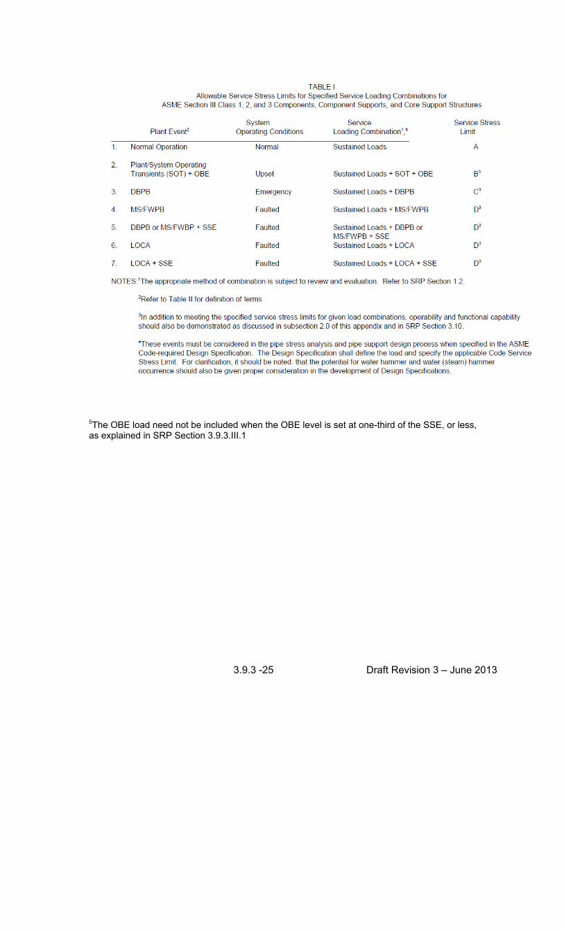
B. Service Loading Combinations. The identification of individual loads and the appropriate combination of these loads (i.e., sustained loads, loads due to system operating transients (SOT), OBE, SSE, LOCA, design basis-pipe break (DBPB), main steam/feedwater pipe break (MS/FWPB) and their dynamic effects) should be in accordance with Section 1.3. The appropriate method of combination of these loads should be in accordance with NUREG-0484, "Methodology for Combining Dynamic Loads.” Exemptions that have been permitted from regulatory requirements to use OBE and the acceptable alternative to use of OBE in the design of components, component supports, and core support structures are described in Subsection III.1 of this SRP section.
C. Service Conditions
(i) Service Limit A. Code Class 1, 2, and 3 components, component supports, and core support structures shall meet a service limit not greater than Level A when subjected to sustained loads resulting from normal plant/system operation.
(ii) Service Limit B. Code Class 1, 2, and 3 components, component supports, and core support structures shall meet a service limit not greater than Level B when subjected to the appropriate combination of loadings resulting from (1) sustained loads, (2) specified plant/SOT, and (3) the OBE. Exemptions that have been permitted from regulatory requirements to use OBE and the acceptable alternative to use of OBE in the design of components, component supports, and core support structures are described in Subsection III.1 of this SRP section.
(iii) Service Limit C.
(1) Code Class 1, 2, and 3 components, component supports, and core support structures shall meet a service limit not greater than Level C when subjected to the appropriate combination of loadings resulting from (1) sustained loads, and (2) the DBPB.
(2) The DBPB includes loads from the postulated pipe break, itself, and
also any associated system transients or dynamic effects resulting from the postulated pipe break.
3.9.3 -23 Draft Revision 3 – June 2013
(iv) Service Limit D. (1) Code Class 1, 2, and 3 components, component supports, and core
support structures shall meet a service stress limit not greater than Level D when subjected to the appropriate combination of loadings resulting from (1) sustained loads, (2) either the DBPB, MS/FWPB, or LOCA, and (3) and SSE.
(2) The DBPB, MS/FWPB, and LOCA include loads from the postulated pipe breaks, themselves, and also any associated system transients or dynamic effects resulting from the postulated pipe breaks. Asymmetric blowdown loads on PWR primary systems should be incorporated per NUREG-0609.
5 FUNCTIONAL CAPABILITY AND OPERATIONAL READINESS
A. Active Pumps and Valves. SRP Section 3.10 provides guidance to reviewers to ensure that applicants demonstrate that pumps or valves, as supported, can adequately sustain the designated combined service loadings at a stress level bounded by the specified service limit. Stresses in valve bodies and pump casings should be limited to the particular material’s elastic limit when the pump or valve is subjected to the combination of normal operating loads, SSE and other applicable loads. Such demonstration provides assurance that pumps and valves can perform their safety function without impairment. Loads produced by the restraint of free end displacement and anchor point motions should be included.
Functional design and qualification of active pumps and valves, and inservice testing programs to assess operational readiness are addressed in SRP Section 3.9.6.
B. Snubbers. The functionality and operational readiness requirements specified for mechanical and hydraulic snubbers installed on safety-related systems are subject to review by the staff. When snubbers are used, their need should be clearly established and their design criteria presented.
SRP Section 3.9.6 addresses inservice testing programs to assess operational readiness of snubbers.
C. Functional Capability of Class 1, 2 and 3 Piping. The design of Class 1, 2, and 3 piping components should include an assessment of the capability of the piping system. This assessment should demonstrate that the piping components, as supported, can retain sufficient dimensional stability at service conditions so as not to impair the system's functional capability. The assessment may be based on tests, analysis, or a combination of tests and analysis. The functional capability assessment should incorporate the conclusions listed in Section 9 of NUREG-1367, "Functional Capability of Piping Systems." Functional capability of piping systems is reviewed in SRP Section 3.12.
3.9.3 -24 Draft Revision 3 – June 2013
6. TABLES
A. Table I summarize the guidance contained in this Appendix. The table illustrates plant events, system operating conditions, service loading combinations, and service stress limits and should be used in conjunction with the text of this appendix.
B. Table II defines terms used in this Appendix. 7. PROCEDURES FOR COMPLIANCE
A. Design Specification and Safety Analysis Report
(i) The design options provided by the Code and related design criteria specified in the Code required Design Specification for Code Class 1, 2, and 3 components, component supports, and core support structures should be summarized in sufficient detail in the safety analysis report of the application to permit comparison with this appendix.
(ii) The presentation in the Preliminary Safety Analysis Report (PSAR) should specify and account for all design and service loadings, method of combination, the designation of the appropriate design and service stress limits (including primary and secondary stresses, fatigue consideration, and special limits on pressure when appropriate) for each loading combination presented, and the provisions for functional capability.
(iii) The presentation in the FSAR should indicate how the criteria in Sections 1
and 2 of this appendix have been implemented. Information regarding design certification review procedures and evaluation findings is offered in Subsections III and IV of SRP Section 3.9.3.
(iv) The staff may request the submission of the Code-required Design Documents (such as Design Specifications, Design Reports, Load Capacity Data Sheets, or other related material or portions thereof), in order to establish that the design criteria, the analytical methods, and functional capability satisfy the guidance provided by this appendix. This may include information provided to, and received from, component and support manufacturers. As an alternative to the applicant submitting these documents, the staff may request them to be made available for review at the applicant's or vendor's office.
B. Use with Regulatory Guides. RG 1.124 and 1.130 on Class 1 linear and Class 1 plate and shell component support structures are supplemented by this appendix.
3.9.3 -25 Draft Revision 3 – June 2013
5The OBE load need not be included when the OBE level is set at one-third of the SSE, or less, as explained in SRP Section 3.9.3.III.1
3.9.3 -26 Draft Revision 3 – June 2013
Active Pumps and Valves - A pump or valve which must perform a mechanical motion in order to shut down the plant or mitigate the consequences of a postulated event. Safety and relief valves are specifically included. Component and Support Functionality and Functional Capability - Ability of a component, including its supports, to deliver rated flow and retain dimensional stability when the design and service loads, and their resulting stresses and strains, are at prescribed levels. Component and Support Operational Readiness - Ability of an active component, including its support, to perform the mechanical motion required to fulfill its designated safety function consistent with operational limits and Technical Specification requirements. Additional discussion of functionality and operational readiness is included in RIS 2005-20, “Revision to Guidance Formerly Contained in NRC Generic Letter 91-18,’Information To Licensees Regarding Two NRC Inspection Manual Sections on Resolution Degraded and Nonconforming Conditions and On Operability,’” dated September 26, 2005. Design Basis Pipe Breaks - Those postulated pipe breaks other than a LOCA or MS/FWPB. This includes postulated pipe breaks in Class 1 branch lines that result in the loss of reactor coolant at a rate less than or equal to the capability of the reactor coolant makeup system. This condition includes loads from the postulated pipe breaks, itself, and also any associated system transients or dynamic effects resulting from the postulated pipe break. Design Limits - The limits for the design loadings provided in the appropriate subsection of Section III, Division 1, of the ASME Code. Design Loads - Those pressures, temperatures, and mechanical loads selected as the design basis for a component. Functional System - That configuration of components which, irrespective of ASME Code Class designation or combination of ASME Code Class designations, performs a particular function (i.e., each emergency core cooling system performs a single particular function and yet each may be comprised of some components which are ASME Class 1 and other components which are ASME Code Class 2). Loss-of-Coolant Accidents - Defined in Appendix A of 10 CFR Part 50 as "those postulated accidents that result from the loss of reactor coolant, at a rate in excess of the capability of the reactor coolant makeup system, from breaks in the reactor coolant pressure boundary, up to and including a break equivalent in size to the double-ended rupture of the largest pipe of the reactor coolant system." This condition includes the loads from the postulated pipe break, itself, and also any associated system transients or dynamic effects resulting from the postulated pipe break. Main Steam and Feedwater Pipe Breaks - Postulated breaks in the main steam and feedwater lines. For a BWR plant this may be considered as a LOCA event depending on the break location. This condition includes the loads from the postulated pipe break, itself, and also any associated system transients or dynamic effects resulting from the postulated pipe break.
3.9.3 -27 Draft Revision 3 – June 2013
Operating Basis Earthquake - Defined in Section III of Appendix S of 10 CFR Part 50 as "that earthquake which, considering the regional and local geology and seismology and specific characteristics of local subsurface material, could reasonably be expected to affect the plant site during the operating life of the plant. It is that earthquake which produces the vibratory ground motion for which those features of the nuclear power plant, necessary for continued operation without undue risk to the health and safety of the public, are designed to remain functional." This condition includes the loads from the postulated seismic event, itself, and also any associated system transients or dynamic effects resulting from the postulated seismic event.
Piping Components - These items of a piping system such as tees, elbows, bends, pipe and tubing, and branch connections constructed in accordance with the rules of Section III of the ASME Code. Postulated Events - Those postulated natural phenomena (i e., OBE, SSE) postulated site hazards (i.e., nearby explosion), or postulated plant events (i.e., DBPB, LOCA, MS/FWPB) for which the plant is designed to survive without undue risk to the health and safety of the public. Such postulated events may also be referred to as design basis events. Safe Shutdown Earthquake - Defined in Section III of Appendix S of 10 CFR Part 50 as that earthquake which is based upon an evaluation of the maximum earthquake potential considering the regional and local geology and seismology and specific characteristics of local subsurface material. It is the earthquake which produces the maximum vibratory ground motion for which certain structures, systems, and components are designed to remain functional. These SSCs are those necessary to ensure: (1) The integrity of the reactor coolant pressure boundary.
(2) The capability to shut down the reactor and maintain it in a safe shutdown condition, or
(3) The capability to prevent or mitigate the consequences of accidents which could result in potential offsite exposures comparable to the guideline."
This condition includes the loads from the postulated seismic event, itself, and also any associated system transients or dynamic effects resulting from the postulated seismic event.
Service Limits - The four limits for the service loading as provided in the appropriate subsection of Section III, Division 1, of the ASME Code.
Service Loads - Those pressure, temperature, and mechanical loads provided in the Design Specification. System Operating Transients - The transients and their resulting mechanical and thermal responses due to dynamic occurrences caused by plant or system operation.
3.9.3 -28 Draft Revision 3 – June 2013
SRP SECTION 3.9.3 Description of Changes
SECTION 3.9.3 “ASME CODE CLASS 1, 2, AND 3 COMPONENTS AND COMPONENT
SUPPORTS, AND CORE SUPPORT STRUCTURES”
This SRP section affirms the technical accuracy and adequacy of the guidance previously provided in Section 3.9.3 Revision 2, dated March 2007, of this SRP. See the Agencywide Documents Access and Management System (ADAMS) Accession No. ML070430397. These sections have been updated to reflect the guidance of “Resolution of Generic Safety Issues: Issue 89, Stiff Pipe Clamps” (GI-89), located in ADAMS Accession No. ML101720320. Technical changes incorporated in this revision 2012 include: I. AREAS OF REVIEW
1. A pointer to SRP Section 3.12 for review of stiff pipe clamp designs and GI-89 was added
to review interfaces section.
II. ACCEPTANCE CRITERIA
2. Added SRP Section II. 3.B. (v) for related criteria for snubber functionality.
3. Replaced SRP Section 3.9.3.III.1 “In the Advanced Boiling-Water Reactor (ABWR) …. Eliminated from design” with the paragraph of the operating-basis earthquake (OBE).
4. References section added references (15), (16), (17) and (18).
APPENDIX A
5. Text replaced from “operability”, ‘operability assurance” to “operational readiness.”
6. Added footnote no. 5 into Table 1.
7. Title changed to read “Section 5, FUNCTIONAL CAPABILITY AND OPERATIONAL READINESS.”