Numerical Study of Interactions Between Phase II of OC4 ...dcwan.sjtu.edu.cn/userfiles/Numerical...
9
Journal of Ocean and Wind Energy (ISSN 2310-3604) http://www.isope.org/publications Copyright © by The International Society of Offshore and Polar Engineers Vol. 2, No. 1, February 2015, pp. 45–53 Numerical Study of Interactions Between Phase II of OC4 Wind Turbine and Its Semi-Submersible Floating Support System Wenchao Zhao and Decheng Wan State Key Laboratory of Ocean Engineering, School of Naval Architecture, Ocean and Civil Engineering Shanghai Jiao Tong University, Shanghai, China The motion response of the floating support system is critical in designing and confirming the safety and efficiency of an offshore wind turbine. This paper aims to study the interaction between the wind turbine and its semi-submersible floating system for Phase II of the Offshore Code Comparison Collaboration Continuation (OC4) project. First, the validation of wave generation and damping is performed to guarantee the accuracy of waves. Then, the grid convergence is studied to eliminate the influence of different grids. Last, the motion of the semi-submersible floating system in specific waves is compared with a parked wind turbine and with an equivalent operated wind turbine. The equivalent forces and moments of the NREL 5-MW in different wind speeds have been exerted on the rotational center of the semi-submersible floating system. The results show the influences of the wind turbine on the supporting system in waves. INTRODUCTION Rapid economic development results in a growing demand for energy. However, traditional energy, such as fossil fuels, has been overexploited, with many environmental and climate problems arising. Nowadays, more and more attention is being paid to new energies to settle the increasingly urgent energy crisis. The clean, renewable and recyclable features of wind energy have been focused on. It is widely recognized that wind energy is the most promising energy among all of the new renewable energies. Many European countries, such as Denmark and the Netherlands, have devoted a large sum of resources to study the utilization of wind energy. Compared with onshore wind energy, offshore wind energy has more advantages, such as high wind speed, stable wind, weak wind shear, and little visual and noise pollution (Zhao and Gong, 2013). With the first offshore wind farm constructed in Sweden in 1990, offshore wind energy began its rapid development. At the end of 2012, the installed capacity of offshore wind power has reached 5 million kilowatts in Europe, and it is planned to reach 40 million kilowatts in 2020 and 150 million kilowatts in 2030 (Zhao and Gong, 2013). The reliability of the supporting platform is a critical factor in the safety design of the offshore wind turbine. At sea, the wind turbine may encounter a variety of wind and wave conditions. The dynamic response of the support system in different circumstances deserves extensive study to maintain security and reliability. Research on the floating foundations has been conducted since the 1990s (Tang et al., 2011). Zhang et al. (2012) analyzed some key dynamic problems and risk factors of the floating structure for working load caused by turbine running and sea environment loads of the floating structure. Roddier et al. (2010) investigated the WindFloat, a floating foundation for offshore wind turbines. Goupee et al. (2012) tested three different floating wind turbine configurations in a wave basin under combined wind/wave loading. There are three common Received November 8, 2014; updated and further revised manuscript received by the editors January 4, 2015. The original version (prior to the final updated and revised manuscript) was presented at the Twenty-fourth International Ocean and Polar Engineering Conference (ISOPE-2014), Busan, Korea, June 15–20, 2014. KEY WORDS: Offshore wind turbine, semi-submersible floating system, OC4, numerical simulation, naoe-FOAM-SJTU solver. floating foundations of the offshore wind turbine: the tension leg platform, the spar foundation, and the semi-submersible platform (Sclavounos, 2008). Gao et al. (2013) adopted the boundary element method and combined with multi-body dynamics, analyzing the motion response and wave force mechanism of the tension leg platform of a floating offshore wind turbine. Utsunomiya et al. (2009) carried out an experimental validation for motion of a 2-MW SPAR-type floating offshore wind turbine. Coulling et al. (2013) validated a model constructed in the National Renewable Energy Laboratory (NREL) floating wind turbine simulator FAST with 1/50th-scale model test data for a semi-submersible floating wind turbine system. The three-column semi-submersible floating platform is used in Phase II of the Offshore Code Comparison Collaboration Continuation (OC4) project (Robertson et al., 2012), which is a verification of modeling by comparing results of simulated responses between tools. Many research works have been done on this platform. Chung (1976) computed the hydrodynamic forces and six degree-of-freedom motion about the famous three-column semi-submersible SEDCO-135 platform with a potential flow theory. Chung (1994) provided experimental data of large-model added mass and damping that commercial programs WADAM and WAMIT cannot match or validate for the three-column semi- submersible platform. Luan et al. (2013) used a novel modeling method based on the code Simo/Riflex to simulate force and moment response in the brace system of a semi-submersible wind turbine. Koo et al. (2014) carried out a model test on three different floating platforms: a spar, a semisubmersible, and a tension-leg platform (TLP). The purpose was to generate data on coupled motions and loads between the three floating platforms and the same wind turbine for the operational, design, and survival sea states. Li et al. (2015) presented an aero-hydro Matlab code for the dynamic analysis of an offshore floating wind turbine and validated with a model test carried out in the Deepwater Offshore Basin at Shanghai Jiao Tong University. However, most research models are 1/50th-scale models, and the research method is based on potential theory. CFD methods in viscous flow fields are not common, but are studied in this project. The wind turbine for OC4 Phase II will be the National Renew- able Energy Laboratory (NREL) offshore 5-MW baseline wind turbine (Jonkman et al., 2009), which has abundant experimental data and simulation results. The aim of this paper is to investigate
Transcript of Numerical Study of Interactions Between Phase II of OC4 ...dcwan.sjtu.edu.cn/userfiles/Numerical...
Journal of Ocean and Wind Energy (ISSN 2310-3604) http://www.isope.org/publicationsCopyright © by The International Society of Offshore and Polar EngineersVol. 2, No. 1, February 2015, pp. 45–53
Numerical Study of Interactions Between Phase II of OC4 Wind Turbineand Its Semi-Submersible Floating Support System
Wenchao Zhao and Decheng WanState Key Laboratory of Ocean Engineering, School of Naval Architecture, Ocean and Civil Engineering
Shanghai Jiao Tong University, Shanghai, China
The motion response of the floating support system is critical in designing and confirming the safety and efficiency of anoffshore wind turbine. This paper aims to study the interaction between the wind turbine and its semi-submersible floatingsystem for Phase II of the Offshore Code Comparison Collaboration Continuation (OC4) project. First, the validation of wavegeneration and damping is performed to guarantee the accuracy of waves. Then, the grid convergence is studied to eliminatethe influence of different grids. Last, the motion of the semi-submersible floating system in specific waves is compared with aparked wind turbine and with an equivalent operated wind turbine. The equivalent forces and moments of the NREL 5-MW indifferent wind speeds have been exerted on the rotational center of the semi-submersible floating system. The results show theinfluences of the wind turbine on the supporting system in waves.
INTRODUCTION
Rapid economic development results in a growing demand forenergy. However, traditional energy, such as fossil fuels, has beenoverexploited, with many environmental and climate problemsarising. Nowadays, more and more attention is being paid to newenergies to settle the increasingly urgent energy crisis. The clean,renewable and recyclable features of wind energy have been focusedon. It is widely recognized that wind energy is the most promisingenergy among all of the new renewable energies. Many Europeancountries, such as Denmark and the Netherlands, have devoteda large sum of resources to study the utilization of wind energy.Compared with onshore wind energy, offshore wind energy hasmore advantages, such as high wind speed, stable wind, weak windshear, and little visual and noise pollution (Zhao and Gong, 2013).With the first offshore wind farm constructed in Sweden in 1990,offshore wind energy began its rapid development. At the end of2012, the installed capacity of offshore wind power has reached 5million kilowatts in Europe, and it is planned to reach 40 millionkilowatts in 2020 and 150 million kilowatts in 2030 (Zhao andGong, 2013).
The reliability of the supporting platform is a critical factor in thesafety design of the offshore wind turbine. At sea, the wind turbinemay encounter a variety of wind and wave conditions. The dynamicresponse of the support system in different circumstances deservesextensive study to maintain security and reliability. Research on thefloating foundations has been conducted since the 1990s (Tanget al., 2011). Zhang et al. (2012) analyzed some key dynamicproblems and risk factors of the floating structure for working loadcaused by turbine running and sea environment loads of the floatingstructure. Roddier et al. (2010) investigated the WindFloat, afloating foundation for offshore wind turbines. Goupee et al. (2012)tested three different floating wind turbine configurations in a wavebasin under combined wind/wave loading. There are three common
Received November 8, 2014; updated and further revised manuscriptreceived by the editors January 4, 2015. The original version (prior to thefinal updated and revised manuscript) was presented at the Twenty-fourthInternational Ocean and Polar Engineering Conference (ISOPE-2014),Busan, Korea, June 15–20, 2014.
KEY WORDS: Offshore wind turbine, semi-submersible floating system,OC4, numerical simulation, naoe-FOAM-SJTU solver.
floating foundations of the offshore wind turbine: the tension legplatform, the spar foundation, and the semi-submersible platform(Sclavounos, 2008). Gao et al. (2013) adopted the boundary elementmethod and combined with multi-body dynamics, analyzing themotion response and wave force mechanism of the tension legplatform of a floating offshore wind turbine. Utsunomiya et al.(2009) carried out an experimental validation for motion of a 2-MWSPAR-type floating offshore wind turbine. Coulling et al. (2013)validated a model constructed in the National Renewable EnergyLaboratory (NREL) floating wind turbine simulator FAST with1/50th-scale model test data for a semi-submersible floating windturbine system.
The three-column semi-submersible floating platform is usedin Phase II of the Offshore Code Comparison CollaborationContinuation (OC4) project (Robertson et al., 2012), which isa verification of modeling by comparing results of simulatedresponses between tools. Many research works have been done onthis platform. Chung (1976) computed the hydrodynamic forcesand six degree-of-freedom motion about the famous three-columnsemi-submersible SEDCO-135 platform with a potential flowtheory. Chung (1994) provided experimental data of large-modeladded mass and damping that commercial programs WADAMand WAMIT cannot match or validate for the three-column semi-submersible platform. Luan et al. (2013) used a novel modelingmethod based on the code Simo/Riflex to simulate force andmoment response in the brace system of a semi-submersible windturbine. Koo et al. (2014) carried out a model test on three differentfloating platforms: a spar, a semisubmersible, and a tension-legplatform (TLP). The purpose was to generate data on coupledmotions and loads between the three floating platforms and thesame wind turbine for the operational, design, and survival seastates. Li et al. (2015) presented an aero-hydro Matlab code for thedynamic analysis of an offshore floating wind turbine and validatedwith a model test carried out in the Deepwater Offshore Basin atShanghai Jiao Tong University. However, most research models are1/50th-scale models, and the research method is based on potentialtheory. CFD methods in viscous flow fields are not common, butare studied in this project.
The wind turbine for OC4 Phase II will be the National Renew-able Energy Laboratory (NREL) offshore 5-MW baseline windturbine (Jonkman et al., 2009), which has abundant experimentaldata and simulation results. The aim of this paper is to investigate

46 Numerical Study of Interactions Between Phase II of OC4 Wind Turbine and Its Semi-Submersible Floating Support System
the NREL 5-MW wind turbine impacts on its semi-submersiblefloating support system for Phase II of OC4 in specified waveconditions based on our own code naoe-FOAM-SJTU solver. Theequivalent method is used to investigate the impacts of the NREL5-MW wind turbine. The equivalent forces and moments are exertedon the rotational center of the floating support system, assum-ing that the wind turbine is working. The forces and motions ofthe semi-submersible floating system have been compared with aparked wind turbine and with an equivalent operated wind turbine.As Phase II of the OC4 project has no experimental data nowadays,the results of this paper are only self-validated. Despite this, ourgroup has done a lot of work to clarify the reliability in dealingwith aerodynamics of the wind turbine (Wang et al., 2012) andthe dynamic responses of the platform in different waves (Liuand Wan, 2013). In this paper, naoe-FOAM-SJTU solver will bedescribed first. Next, the geometry model, governing equations, anddiscretization schemes are introduced to configure the cases in dif-ferent wind speeds. In addition, the wave generation and dampingvalidation are used to show the accuracy of the numerical wavetank. Grid convergence is also used to clarify the independence ofthe grid. Then, the results are compared to show the impacts of theNREL 5-MW wind turbine. Finally, a conclusion is drawn.
NUMERICAL SIMULATION
naoe-FOAM-SJTU Solver
The solver adopted in this paper is our own code naoe-FOAM-SJTU (Shen, Cao, and Wan, 2012) (hereafter referred to as Solver1), which is based on open source code OpenFOAM platform.Solver 1 was developed to deal with the hydrodynamic problemsof naval architecture and ocean engineering in which the RANSequations are discretized by finite volume method, the surfaceinterface is captured by VOF method, and motions of ship andocean structures in waves are handled by dynamic deformationmesh approach (Shen, Ye, and Wan, 2012). This solver has severalmodules, such as a wave generation and damping module, sixdegree-of-freedom (6DoF) module, and mooring line module, tosolve different problems. A numerical tank system is formed by thewave generation and damping module. Different methods such aspiston, flap, and boundary inlet are used to generate first- and high-order nonlinear waves, transient extreme waves, and freak waves.Cha and Wan (2011) first achieved the piston-type and flap-typenumerical method to obtain the linear wave and finite amplitudewaves based on interDyMFoam in OpenFOAM. In order to absorbthe wave at the end of the wave tank, a damping zone is set at theappropriate location. The 6DoF module, developed by Shen andWan (2013), is used to predict the dynamic motions of ship andocean structures in different waves. The mooring lines module isdeveloped to handle the motion problems of floating structuresin deep sea. Liu and Wan (2013) studied a series of numericalsimulations of the interaction of a triple-hulled observation platformwith different incident waves. Cao et al. (2013) analyzed the waveloading on a floating platform coupled with a mooring system.
Solver 1 has proved to be competent in solving the floatingplatform movement in waves, which provides solid support forthis paper. A test case conducted by Solver 1 is presented here.The model is a deepwater semi-submersible drilling platform, asshown in Fig. 1. The parameters of the model are set in accordancewith the experiment by Shi et al. (2011), which performed thewhite noise test, regular wave test, and numerical simulation bySESAM in multiple sets of waves. The motion response of thesemi-submersible platform is simulated by Solver 1 under theeffect of three different periods of incident waves. The motionresponse amplitude operator (RAO) of surge, heave, and pitch are
Fig. 1 Deepwater semi-submersible drilling platform model
compared with Shi et al.’s experiment and numerical results, whichare shown in Figs. 2, 3, and 4. In these figures, it is clearly shownthat the motion response of the semi-submersible platform in wavessimulated by Solver 1 is reliable and close to the experimentalresults. Based on the test, in the following numerical computations,the motion response of the three-column semi-submersible platformof OC4 is numerically investigated by using the same solver.
Geometry Model
The geometry model for Phase II of the OC4 project is a semi-submersible floating offshore wind system, as shown in Fig. 5. Froma report by the National Renewable Energy Laboratory (Robertson
Fig. 2 Comparison of RAO (surge)
Fig. 3 Comparison of RAO (heave)

Journal of Ocean and Wind Energy, Vol. 2, No. 1, February 2015, pp. 45–53 47
Fig. 4 Comparison of RAO (pitch)
Fig. 5 DeepCwind floating wind system design
et al., 2012), the OC4 project compares dynamic computer codesand models used to design offshore wind turbines and supportstructures. Nowadays, many agencies and institutions are dedicatedto studying this project as a floating standard model.
This paper is based on this model to explore the wind turbineimpacts on the semi-submersible floating support system. As weknow, the coupled solution of aerodynamic and hydrodynamicproblems is very complicated. To simplify this problem, theequivalent method has been applied, which will be described indetail later. The semi-submersible design examined in this phase isbased on the as-built configuration used in the DeepCwind tests,
Fig. 6 As-built picture of semi-submersible floating system
Depth of platform base below SWL (total draft) 20 mElevation of main column (tower base) above SWL 10 mElevation of offset columns above SWL 12 mSpacing between offset columns 50 mLength of upper columns 26 mLength of base columns 6 mDepth to top of base columns below SWL 14 mDiameter of main column 6.5 mDiameter of offset (upper) columns 12 mDiameter of base columns 24 mDiameter of pontoons and cross braces 1.6 m
Table 1 Floating platform geometry
as shown in Fig. 6. However, the wind turbine specification forOC4 Phase II will be the National Renewable Energy Laboratory(NREL) offshore 5-MW baseline wind turbine (Jonkman et al.,2009), which is a representative multi-MW turbine. This turbinewill be used in all phases of OC4.
As shown in Fig. 5, the tower is cantilevered at an elevationof 10 m above the still water lever (SWL) to the top of the maincolumn. The draft of the platform is 20 m. The DeepCwind semi-submersible consists of a main column attached to the tower plusthree offset columns that are connected to the main column througha series of smaller-diameter pontoons and cross members. Theparameters of this floating platform, including the diameters ofeach of the members, are given in Table 1.
Forces and Moments of Equivalent Wind Turbine
This paper uses the equivalent method to study wind turbineimpacts on its semi-submersible floating support system. Referringto the NREL 5-MW wind turbine, the average of forces andmoments of the wind turbine at different wind speeds are exertedon the rotational center of the semi-submersible floating system.Figure 7 shows the results from the NREL of the wind turbineat different wind speeds (Jonkman et al., 2009). A steady-stateresponse of the land-based 5-MW wind turbine is done by runninga series of FAST (an aeroelastic computer-aided engineering (CAE)tool for horizontal axis wind turbines) (Jonkman and Buhl Jr, 2005)with AeroDyn (aerodynamics analysis routines for horizontal-axiswind turbine dynamics analyses) (Moriarty and Hansen, 2005)simulations at a number of given, steady, and uniform wind speeds.The steady-state results are suggested by NREL to mitigate thestart-up transient behavior, which is an artifact of computationalanalysis.
In Fig. 7, RotThrust represents the rotor thrust, and RotTorqrepresents the mechanical torque in the low-speed shaft. The rotor
Fig. 7 Forces and moments of NREL 5-MW wind turbine
48 Numerical Study of Interactions Between Phase II of OC4 Wind Turbine and Its Semi-Submersible Floating Support System
thrust and torque of wind speeds 5 m/s, 7 m/s, and 11.4 m/s havebeen picked up. However, the data are measured at the rotationalcenter of the blades, which is located 87.6 m above the SWL. Thus,the theorem of translation of force has been applied to computethe forces and moments about the rotational center of the semi-submersible floating supporting system. There will be an additionaltorque generated in the translation of a force.
The formulas of this theorem are:
EF ′= EF (1)
EM ′= EM + r × EF (2)
where r is the distance between the center of the blades and therotational center of the semi-submersible floating support system, EFand EM are the forces and moments obtained from the experimentaldata, and EF ′ and EM ′ are the forces and moments exerted on thesupport system.
Governing Equations
In order to solve the unsteady, incompressible, and viscous fluid,the three-dimensional incompressible Reynolds-Averaged Navier-Stokes (RANS) equations are chosen as the governing equations,which can be written in vector form as:
ï ·U = 0 (3)
¡�U
¡t+ï · 4�UU5
= −ïp− g · xï�+ï · 4�effïU5+ 4ïU5 ·ï�eff + f� (4)
where U is the velocity field; � is the density of the fluid; g isthe acceleration due to gravity; p is the pressure; �eff = �4� + �t5is the efficient dynamic viscosity, in which � is the kinematicviscosity and �t is the turbulence kinetic viscosity, which is givenby the SST k-� turbulence model (Menter, 1994); f� is the surfacetension term in two-phase model.
The solution of the governing equations is obtained with a newalgorithm called PIMPLE (merged PISO-SIMPLE), which is acombination of pressure-implicit split-operator (PISO) proposed byIssa (1986) and semi-implicit method for pressure-linked equations(SIMPLE) proposed by Patankar and Spalding (1972), to decouplethe pressure-velocity coupling equation. This algorithm regards theflow as a steady-state flow at each time step, then uses the standardPISO algorithm to complete the progressive of the time step, whichaccelerates the convergence time of the whole process of solving.
Discretization Schemes
The governing equations are discretized based on the FiniteVolume Method (FVM) (Versteeg and Malalasekera, 2007). Theunsteady term applies the Euler scheme. The Gauss limitedLinearV1 scheme is employed to discretize the convective term, while theGauss linear corrected is used to discretize the diffusive term. TheVOF method (Hirt and Nichols, 1981) is adopted in Solver 1 totrack the free surface, which is discretized by the Gauss vanLeerscheme. The gradient term uses the Gauss linear scheme, and theinterpolation term applies the linear scheme.
NUMERICAL RESULTS
Model Configurations
The purpose of this paper is to study the wind turbine impacts onits semi-submersible floating system in waves. The water depth d is
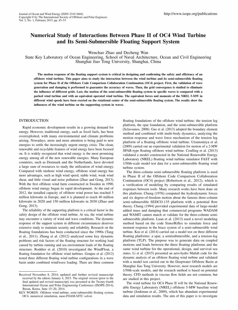
Sea state T (s) H (m)
1 2.0 0.092 4.8 0.673 6.5 1.404 8.1 2.445 9.7 3.666 11.3 5.497 13.6 9.148 17.0 15.24
Table 2 Periodic sea state definitions
determined as 200 m. According to the practical periodic sea statesdefined in Table 2 (from 1 = mild to 8 = extreme sea state), the seastate 5 has been chosen as the wave condition used in this paper.
As seen in Table 2, the specific wave height H is 3.66 m andthe period T is 9.7 s, which is a strong wave condition. Accordingto the wave theory, the wave length L, the wave number k, and thefrequency � can be acquired by formulas below:
L=gT 2
2�= 14609 m (5)
k =2�L
= 0004277 m−1 (6)
�=2�T
= 0064775 s−1 (7)
As the wave length L is 146.9 m and the water depth d is 200 m,the x range is set from −148 m to −280 m. In order to absorb thewave adequately at the end of the wave tank, the damping zone isset from 140 m to 280 m, close to one wave length. The widthof the wave tank is 240 m and the height is set from −200 m to−50 m, as shown in Fig. 8.
This paper validates the wave generation and wave damping firstto eliminate the interference of wave inaccuracy. Then the gridconvergence verification is used to guarantee the independence ofdensity of grid. Last, three sets of results (wind speeds of 5 m/s,7 m/s, and 11.4 m/s, respectively) are compared to analyze thedegree of influence on the semi-submersible floating support system.In this paper, case 1 is the floating system without the equivalentforces and moments of the wind turbine, and case 2 is the floatingsystem including the equivalent forces and moments of the windturbine. The model is shown in Fig. 9.
Validation of Wave Generation and Damping
The wave generation and damping are verified by the 2-Dnumerical wave tank, whose results can expand to the 3-D numerical
Fig. 8 Computational domain and free surface

Journal of Ocean and Wind Energy, Vol. 2, No. 1, February 2015, pp. 45–53 49
Fig. 9 Model of the semi-submersible platform
wave tank. In order to test the height of the wave generation in thedifferent positions of the tank, four wave gauges (x = −140 m,0 m, 140 m, 249 m) are set to obtain the data. The results arecompared with the theoretical solution. From wave theory, thetheoretical height of the wave surface of Stokes second-order canbe computed by the formula below:
� =H
2cos 4kx−�t5
+H
8
(
�H
L
)
·cosh kd
sinh3 kd4cosh 2kd+ 25 cos 424kx−�t55
(8)
where H is the wave height, L is the wave length, d is the waterdepth, k is the wave number, and � is the wave frequency. Theabove parameters are already known in the model configurations.By the comparison of the numerical and theoretical values, theaccuracy of the wave generation and damping can be guaranteed.
Figure 10 shows the comparison results of wave elevation atfour wave gauges. The first three graphs display the results ofwave generation from 0 s to 150 s at the different positions. Ingeneral, the numerical simulation results and theoretical solutionhave high agreements except for some subtle differences in thecrest and trough of the wave. The wave crests of the theoreticalsolution are a little higher than the numerical values due to thefailure of wave theory to consider the viscosity of the fluid and thesurface tension effects. On the other hand, there are nonlinearityand high-order components in the simulation process that mayinfluence these results. The last graph is the demonstration of thewave damping area. The results illustrate that the wave height hasbeen reduced significantly, where it is less than 10 percent of theoriginal wave height. This shows the efficiency of the sponge layerzone. In conclusion, the wave generation and damping in this paperare accurate and reliable.
Fig. 10 Comparison of numerical and wave theory results
Fig. 11 Global mesh of the computational domain
Fig. 12 Local mesh of the supporting platform
Grid Convergence Verification
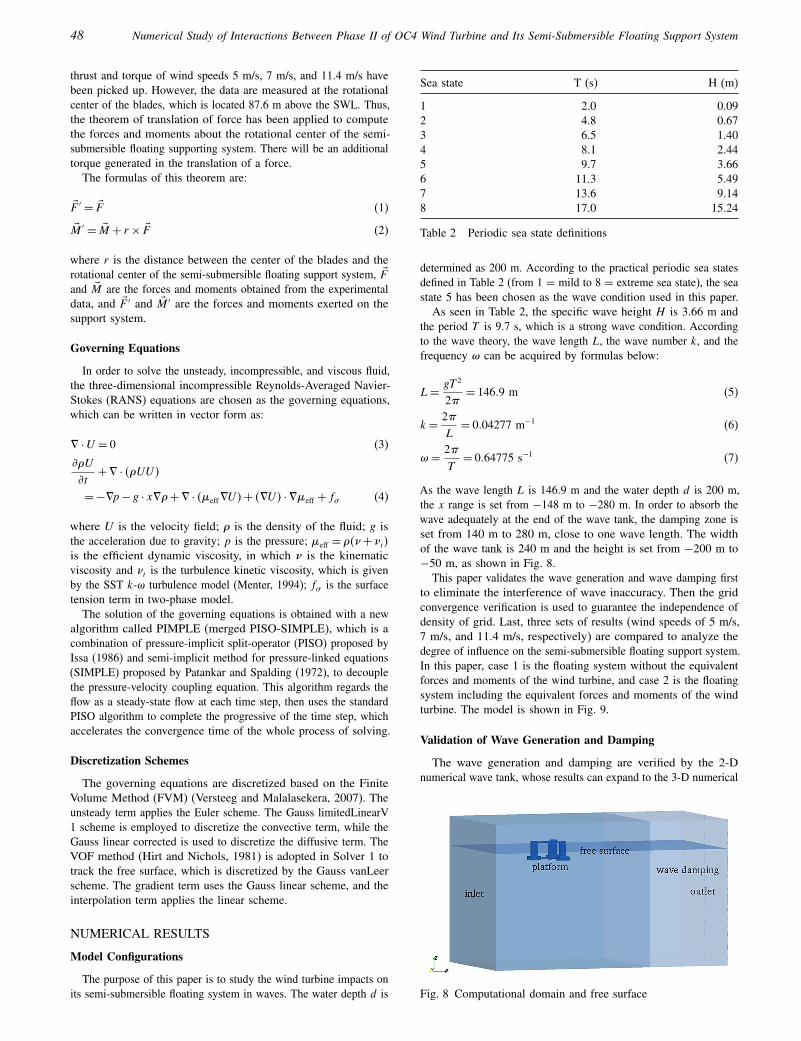
Due to the limited computing resources and costs, reasonablegrid numbers must be applied in the numerical simulation of thispaper. The validation of the grid convergence has been done toensure the effectiveness of the results with proper grid numbers.The mesh is generated with ANSYS ICEM-CFD software andOpenFOAM’s built-in snappyHexMesh utility. The backgroundmesh is generated by the ANSYS ICEM-CFD software. Thenthe mesh around the semi-submersible floating supporting systemis achieved by the snappyHexMesh utility. This utility generatesthree-dimensional meshes containing hexahedra and split-hexahedraautomatically from the STL surface. The global mesh and localmesh of the semi-submersible floating system are shown in Fig. 11and Fig. 12, respectively.
To verify the grid convergence, three different groups of gridnumbers have been compared. The grid numbers are shown inTable 3, and the comparison results are presented in Fig. 13 andFig. 14. Mesh 1 has the most sparse grid and mesh 3 has thefinest grid. By the computation of these three sets of grid numbers,numerical results are observed and analyzed. Figure 13 showsthat the wave forces and moments are almost the same. In thecomparison of the heave and pitch motions of the semi-submersiblefloating system, the results are relatively consistent, except for
Mesh type Background grid numbers Total grid numbers
1 885552 9765902 1221760 13373793 1501552 1625359
Table 3 Three mesh types
50 Numerical Study of Interactions Between Phase II of OC4 Wind Turbine and Its Semi-Submersible Floating Support System
Fig. 13 Comparison of forces and moments of three mesh types
Fig. 14 Comparison of motions of three mesh types
small differences. The comparison results indicate that these threegrids tend to convergence. The influence of grid numbers can beeliminated and the simulation results are reliable. Thus, mesh 2 ischosen as the final mesh to complete all the simulations below.
Forces and Moments on the Semi-Submersible Floating System
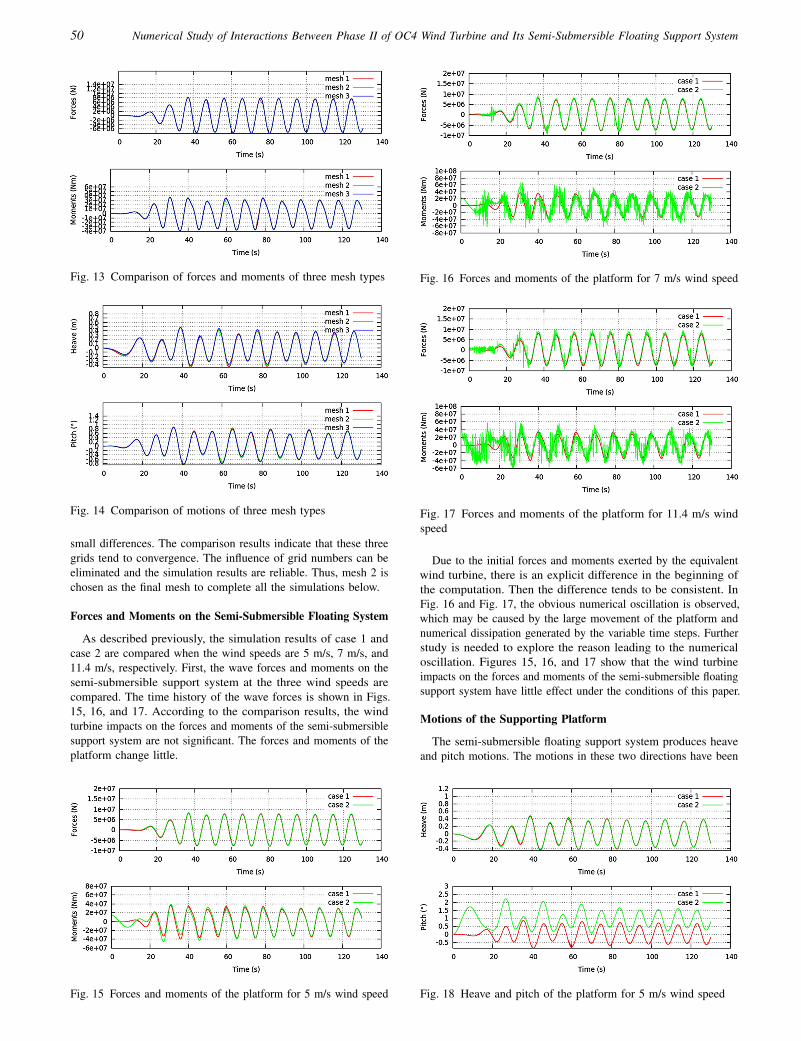
As described previously, the simulation results of case 1 andcase 2 are compared when the wind speeds are 5 m/s, 7 m/s, and11.4 m/s, respectively. First, the wave forces and moments on thesemi-submersible support system at the three wind speeds arecompared. The time history of the wave forces is shown in Figs.15, 16, and 17. According to the comparison results, the windturbine impacts on the forces and moments of the semi-submersiblesupport system are not significant. The forces and moments of theplatform change little.
Fig. 15 Forces and moments of the platform for 5 m/s wind speed
Fig. 16 Forces and moments of the platform for 7 m/s wind speed
Fig. 17 Forces and moments of the platform for 11.4 m/s windspeed
Due to the initial forces and moments exerted by the equivalentwind turbine, there is an explicit difference in the beginning ofthe computation. Then the difference tends to be consistent. InFig. 16 and Fig. 17, the obvious numerical oscillation is observed,which may be caused by the large movement of the platform andnumerical dissipation generated by the variable time steps. Furtherstudy is needed to explore the reason leading to the numericaloscillation. Figures 15, 16, and 17 show that the wind turbineimpacts on the forces and moments of the semi-submersible floatingsupport system have little effect under the conditions of this paper.
Motions of the Supporting Platform
The semi-submersible floating support system produces heaveand pitch motions. The motions in these two directions have been
Fig. 18 Heave and pitch of the platform for 5 m/s wind speed
Journal of Ocean and Wind Energy, Vol. 2, No. 1, February 2015, pp. 45–53 51
Fig. 19 Heave and pitch of the platform for 7 m/s wind speed
Fig. 20 Heave and pitch of the platform for 11.4 m/s wind speed
exported, and comparison is performed to clarify the degree ofinfluence attributable to the wind turbine, as shown in Figs. 18, 19,and 20. It can be seen that the wind turbine has great impact onthe movements of the semi-submersible floating support system,especially the pitch motion. When the wind speed is 5 m/s, theheave motion is almost the same with case 1. As the wind speedincreases, the heave motion becomes larger with small amplitude.At a certain moment, the heave motion reaches a maximum value.However, the pitching motion changes dramatically with a higherwind speed. The pitching motion is less than 1° in case 1, whilethe pitch amplitude reaches nearly 6° in case 2 when the windspeed of the wind turbine is 11.4 m/s. That means that the windturbine has a remarkable impact on the pitching motion of thesemi-submersible floating support system. The supporting platformis in danger of overturning in extreme sea conditions, and themooring line should be used under these conditions.
Velocity and Pressure of the Free Surface
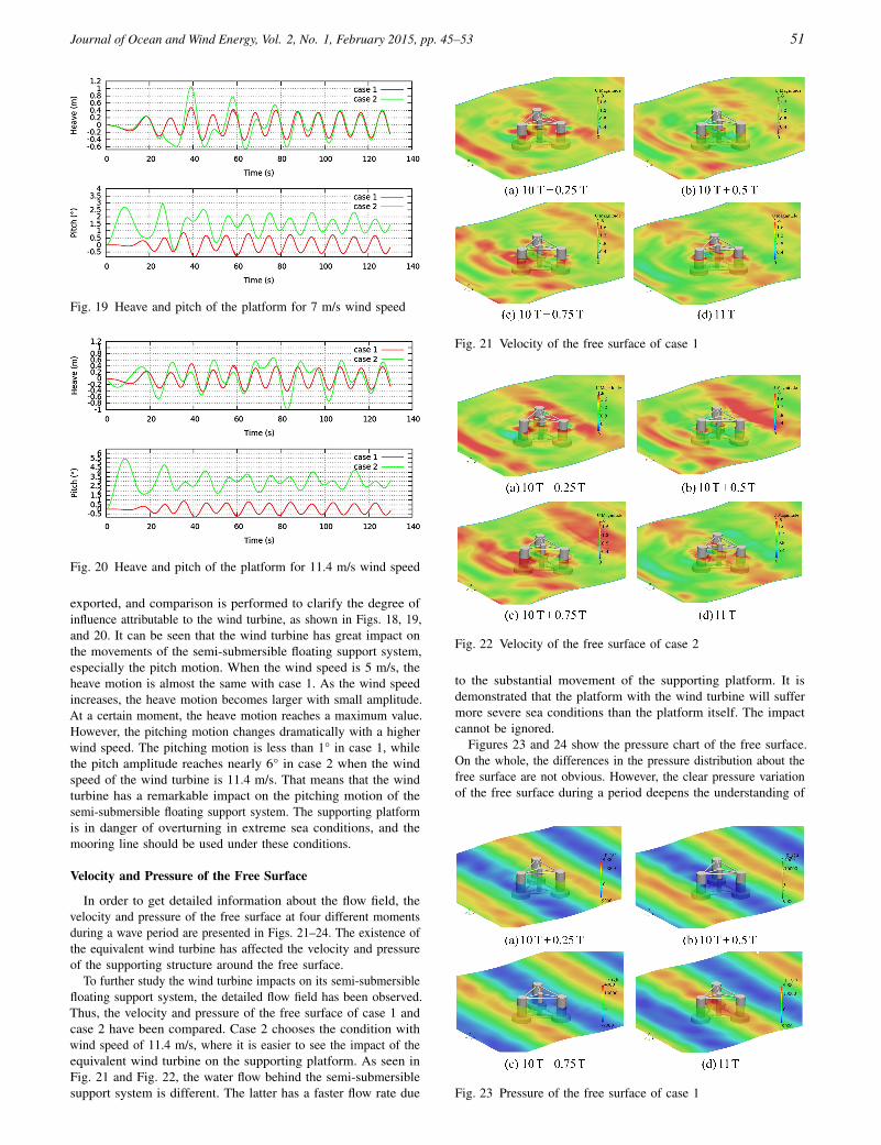
In order to get detailed information about the flow field, thevelocity and pressure of the free surface at four different momentsduring a wave period are presented in Figs. 21–24. The existence ofthe equivalent wind turbine has affected the velocity and pressureof the supporting structure around the free surface.
To further study the wind turbine impacts on its semi-submersiblefloating support system, the detailed flow field has been observed.Thus, the velocity and pressure of the free surface of case 1 andcase 2 have been compared. Case 2 chooses the condition withwind speed of 11.4 m/s, where it is easier to see the impact of theequivalent wind turbine on the supporting platform. As seen inFig. 21 and Fig. 22, the water flow behind the semi-submersiblesupport system is different. The latter has a faster flow rate due
Fig. 21 Velocity of the free surface of case 1
Fig. 22 Velocity of the free surface of case 2
to the substantial movement of the supporting platform. It isdemonstrated that the platform with the wind turbine will suffermore severe sea conditions than the platform itself. The impactcannot be ignored.
Figures 23 and 24 show the pressure chart of the free surface.On the whole, the differences in the pressure distribution about thefree surface are not obvious. However, the clear pressure variationof the free surface during a period deepens the understanding of
Fig. 23 Pressure of the free surface of case 1

52 Numerical Study of Interactions Between Phase II of OC4 Wind Turbine and Its Semi-Submersible Floating Support System
Fig. 24 Pressure of the free surface of case 2
the pressure field. More work should be done to discuss the otherconditions where wind speeds are higher.
CONCLUSIONS
In this paper, the wind turbine impacts on its semi-submersiblefloating support system in a specific wave have been studied withour naoe-FOAM-SJTU solver. To solve the coupling of aerodynamicand hydrodynamic problems of the floating platform and windturbine, an equivalent method has been adopted. The equivalentforces and moments of the NREL 5-MW wind turbine were exertedon the semi-submersible floating system. The results of threewind speeds have been compared. To ensure the reliability of thesimulation results, wave generation and damping have been verified,and grid convergence study has been performed.
In order to analyze the wind turbine impacts on its semi-submersible floating support system, the numerical simulationresults of case 1 and case 2 have been compared. As shownabove, the wind turbine leads to substantial movement of the semi-submersible platform, especially the pitch motion. It can remindthe designers to strengthen the safety design of the platform ofthe floating wind turbine at sea. In addition, the flow informationintuitively displays the velocity and pressure changes of the freesurface and the impacts of the wind turbine. The wind turbinemainly affects the velocity field of the free surface behind thesupporting platform.
The conclusion can be made that the wind turbine has apparentimpacts on its semi-submersible floating support system in waves,especially the pitch motion at high wind speed. This paper is apreliminary exploration of the wind turbine impacts on its floatingsupport system. Subject to constraints, the mooring lines were notadded to the semi-submersible support system. In the future, thedynamic response of the floating platform of the wind turbine withmooring lines is a promising research direction. Much further workshould be performed to investigate this problem.
ACKNOWLEDGEMENTS
The authors are most grateful for the support of this work fromthe National Natural Science Foundation of China (Grant Nos.51379125, 51411130131, and 11432009), the National Key BasicResearch Development Plan (973 Plan) Project of China (GrantNo. 2013CB036103), the High Technology of Marine ResearchProject of The Ministry of Industry and Information Technology ofChina, the Program for Professor of Special Appointment (EasternScholar) at Shanghai Institutions of Higher Learning (Grant No.
2013022), ABS (China), and the Center for HPC at Shanghai JiaoTong University.
REFERENCES
Cao, HJ, Wang, XY, Liu, YC, and Wan, DC (2013). “NumericalPrediction of Wave Loading on a Floating Platform Coupledwith a Mooring System,” Proc 23rd Int Offshore Polar Eng Conf,Anchorage, AK, USA, ISOPE, 3, 582–589.
Cha, JJ, and Wan, DC (2011). “Numerical Wave Generation andAbsorption Based on OpenFOAM,” China Ocean Eng, 29(3),1–12.
Chung, JS (1976). “Motion of a floating structure in water ofuniform depth,” J Hydronaut, AIAA, 10(3), 65–73.
Chung, JS (1994). “Added Mass and Damping on an OscillatingSurface-Piercing Circular Column with a Circular Footing,” Int JOffshore Polar Eng, ISOPE, 4(1), 11–17.
Coulling, AJ, Goupee, AJ, Robertson, AN, Jonkman, JM, andDagher, HJ (2013). “Validation of a FAST Semi-SubmersibleFloating Wind Turbine Numerical Model with DeepCwind TestData,” J Renewable Sustainable Energy, 5(2), 023116.
Gao, YW, Li, C, and Cheng, X (2013). “Performance Research onTension Leg Platform of Floating Offshore Wind Turbine,” AdvMater Res, 724–725, 645–648.
Goupee, AJ, Koo, B, Lambrakos, K, and Kimball, R (2012).“Model Tests for Three Floating Wind Turbine Concepts,” Pre-sented at Offshore Technology Conference, Houston, TX, USA,http://dx.doi.org/10.4043/23470-MS.
Hirt, CW, and Nichols, BD (1981). “Volume of Fluid (VOF)Method for the Dynamics of Free Boundaries,” J Comput Phys,39(1), 201–225.
Issa, RI (1986). “Solution of the Implicitly Discretized Fluid FlowEquations by Operator-Splitting,” J Comput Phys, 62(1), 40–65.
Jonkman, JM, and Buhl Jr, ML (2005). FAST User’s Guide,Technical Report NREL/EL-500-38230, National RenewableEnergy Laboratory, Golden, CO, USA.
Jonkman, JM, Butterfield, S, Musial, W, and Scott, G (2009).Definition of a 5-MW Reference Wind Turbine for OffshoreSystem Development, Technical Report NREL/TP-500-38060,National Renewable Energy Laboratory, Golden, CO, USA.
Koo, BJ, Goupee, AJ, Kimball, RW, and Lambrakos, KF (2014).“Model Tests for a Floating Wind Turbine on Three DifferentFloaters,” J Offshore Mech Arct Eng, 136(2), 021904.
Li, L, Hu, ZQ, Wang, J, and Ma, Y (2015). “Development andValidation of an Aero-hydro Simulation Code for OffshoreFloating Wind Turbine,” J Ocean Wind Energy, ISOPE, to bepublished February 2015.
Liu, YC, and Wan, DC (2013). “Numerical Simulation of MotionResponse of an Offshore Observation Platform in Waves,” J MarSci Appl, 12(1), 89–97.
Luan, C, Gao, Z, and Moan, T (2013). “Modelling and Analysis ofa Semi-Submersible Wind Turbine with a Central Tower withEmphasis on the Brace System,” Proc 32nd Int Conf OceanOffshore Arct Eng, Nantes, France, ASME, 8, V008T09A024.
Menter, FR (1994). “Two-Equation Eddy-Viscosity TurbulenceModels for Engineering Applications,” AIAA J, 32(8), 1598–1605.
Moriarty, PJ, and Hansen, AC (2005). AeroDyn Theory Manual,Technical Report NREL/TP-500-36881, National RenewableEnergy Laboratory, Golden, CO, USA.

Journal of Ocean and Wind Energy, Vol. 2, No. 1, February 2015, pp. 45–53 53
Patankar, SV, and Spalding, DB (1972). “A Calculation Procedurefor Heat, Mass and Momentum Transfer in Three-DimensionalParabolic Flows,” Int J Heat Mass Transfer, 15(10), 1787–1806.
Robertson, A, et al. (2012). Definition of the SemisubmersibleFloating System for Phase II of OC4, Technical Report NREL/TP-5000-60601, National Renewable Energy Laboratory, Golden,CO, USA.
Roddier, D, Cermelli, C, Aubault, A, and Weinstein, A (2010)."WindFloat: A Floating Foundation for Offshore Wind Turbines,”J Renewable Sustainable Energy, 2(3), 033104.
Sclavounos, P (2008). “Floating Offshore Wind Turbines,” MarTechnol Soc J, 42(2), 39–43.
Shen, ZR, and Wan, DC (2013). “RANS Computations of AddedResistance and Motions of Ship in Head Waves,” Int J OffshorePolar Eng, ISOPE, 23(4), 263–271.
Shen, ZR, Cao, HJ, and Wan, DC (2012). Manual of CFD Solverfor Ship and Ocean Engineering Flows: naoe-FOAM-SJTU, Tech-nical Report for Solver Manual, Shanghai Jiao Tong University,Shanghai, China.
Shen, ZR, Ye, HX, and Wan, DC (2012). “Motion Response andAdded Resistance of Ship in Head Waves Based on RANSSimulations,” Chin J Hydrodyn Ser A, 27(6), 621–633.
Shi, QQ, Yang, JM, and Xiao, LF (2011). “Research on Motion andHydrodynamic Characteristics of a Deepwater Semi-Submersible
by Numerical Simulation and Model Test,” The Ocean Engineer-ing, 29(4), 29–36.
Tang, Y, Hu, J, and Liu, L (2011). “Study on the Dynamic Responsefor Floating Foundation of Offshore Wind Turbine,” Proc 30thInt Conf Ocean Offshore Arct Eng, Rotterdam, Netherlands,ASME, 5, 929–933.
Utsunomiya, T, Sato, T, Matsukuma, H, and Yago, K (2009).“Experimental Validation for Motion of a Spar-Type FloatingOffshore Wind Turbine Using 1/22.5 Scale Model,” Proc 28thInt Conf Ocean Offshore Arct Eng, Honolulu, HI, USA, ASME,4, 951–959.
Versteeg, HK, and Malalasekera, W (2007). An Introduction toComputational Fluid Dynamics: The Finite Volume Method,Pearson Education, 503 pp.
Wang, Q, Zhou, H, and Wan, DC (2012). “Numerical Simulation ofWind Turbine Blade-Tower Interaction,” J Mar Sci Appl, 11(3),321–327.
Zhang, RY, Chen, CH, Tang, YG, and Huang, XY (2012). “ResearchDevelopment and Key Technical on Floating Foundation forOffshore Wind Turbines,” Adv Mater Res, 446, 1014–1019.
Zhao, XL, and Gong, WM (2013). “Development of FloatingOffshore Wind Turbine and the Mooring System,” Adv MaterRes, 790, 634–637.
Proceedings of the 11th (2014) ISOPE Pacific/AsiaOffshore Mechanics Symposium (PACOMS-2014 Shanghai)
Shanghai, China, October 12–17, 2014
Hydrodynamics Coastal Hydrodynamics Arctic Transport & Ice MechanicsGeomechanics Offshore Wind & Ocean Energy Floating Structures & Operations
The Proceedings (ISBN 978-1-880653-90-6; ISSN 1946-004x), 432 pp: $100 (ISOPE Member; $80)in a single volume (CD-ROM) available from www.isope.org ([email protected]), ISOPE, 495 NorthWhisman Road, Suite 300, Mountain View, CA 94043, USA (Fax+1-650-254-2038)