Numerical Study and Comparison of Various Types of ...
17
Turkish Journal of Computer and Mathematics Education Vol.12 No 13 (2021), 4548-4564 Research Article 4548 Numerical Study and Comparison of Various Types of Insulation Systems in Terms of Controlling Heat in Cryogenic Tanks Sobhan Safavi Manesh a a Energy Conversion Mechanical Engineering, Malek -Ashtar University of Technology, Iran. Article History: Received: 5 April 2021; Accepted: 14 May 2021; Published online: 22 June 2021 Abstract: This study aimed to numerically compare the thermal performance of various insulation systems and also to maximally reduce the ambient heat transferred to the cryogenic fluid stored in a tank. For this, we use such techniques as vacuum insulation, cryogenic cold shell around the main tank, multilayer insulation, two-sided insulation around the external tank, polyurethane insulation and anti-radiation coatings. The findings suggest that the thermal emissivity and vacuum pressure as well as the vacuum thickness are critical parameters affecting the inlet thermal emission to the main tank. The use of a cryogenic cold shell in a vacuum space is shown to cause a significant drop in the inlet thermal emission to the tank. Considering the separator material inside the various layers of different thicknesses, the multi-layer insulation is also modeled. In this situation, a layer density of 26 cm -1 has been regarded as the best layer density. Finally, while modeling several examples of composite insulation, the intra-tank evaporation rate for each insulation and the feasibility of using the mentioned insulation in Iran are provided. Keywords: Vacuum insulation, Cold vapor shell, Multilayer Insulation, Polyurethane Insulation, Anti-Radiation Coatings, Intra- tank Evaporation Rate 1. Introduction Today, controlling heat in tanks containing cryogenic fluid is very much significant. Cryogenic fluids are referred to fluids with very low boiling points, meaning that these fluids can experience great volume variations at ambient temperatures. To store fluids of very low boiling temperatures, a specifically-insulated tank is required and care should be taken in this case [1]. It is known the lower the heat transferred to the pressure tank and the cryogenic fluid, the lower the evaporation rate. A tank with this feature is considered to be a reliable tank to store cryogenic fluids [2]. The heat transferred to the cryogenic fluid and the creation of a biphasic fluid are performed by three mechanisms: conduction, convection, and radiation. It is common to use vacuum insulation systems to reduce conductive and convective heat transfer [3] while thermal shields are the best option to reduce radiative heat transfer [4-5]. A double-walled vacuum tank was first used by James Doyer in 1898 to store liquid hydrogen [6-8]. It is important not to disregard the radiative heat transfer in any way when analyzing and selecting the type of insulation, for it may cause significant errors in the design and selection of the best insulation. Therefore, it is advised to focus on all three heat transfer mechanisms when examining and selecting the type of insulation. Another method to reduce conductive and convective heat transfer is to use multilayer insulation to store energy. Mehdi Ma’reft and Ismaili demonstrated in a study that to have a desirable design, separat ors in the cold boundary should be selected from materials of low thermal conductivity, and it was necessary to increase the layer density in the vicinity of the warm boundary [9]. Theoretical and experimental works to reduce the conductive and radiative heat transfer is led by researchers such as Clair [10]. In most of these studies, high optical thickness approximation has been used to model radiation [11, 12]. In another study by Mehdi Ma’reft and Arash Ismaili, the two-flux approximation was applied to simulate radiation, which is valid for all ranges of light thickness with radiative properties of solid walls being taken into account in it [9]. In an experimental work by Mills, water vapor and other residual gases were removed between two internal and external tanks by a vacuum pump. For a high vacuum zone to be created, the space between the two walls was first washed once with nitrogen gas and again with helium gas, and then, a vacuuming operation was carried out. The vacuum is 10 −4 Pa before the tank is filled with liquid nitrogen and 10 −5 Pa after being filled with liquid nitrogen. When pumping starts, the amount of thermal leakage from the insulation is calculated. At the onset, the amount of leakage is high due to the presence of gases between the two walls, with the thermal leakage gradually decreasing. In a steady state, when the vacuum is complete, the thermal leakage, after a while, reaches a constant value of 0.227 W m 2 [13]. Saberi Moghadam et al. [14] examined the performance of various insulation systems in storage tanks of cryogenic propulsion systems. They concluded that in an atmospheric state, the conductivity coefficient of helium was higher than that in air, but in high vacuum conditions, the conductive heat transfer of helium was lower. Therefore, under high vacuum conditions, the conductive heat transfer mechanism is different from that in atmospheric conditions. In a study, Nassett et al. [15] examined multilayer insulation of hydrogen tanks. This study provides some suggestions for insulating these tanks. In an experimental work, Dai et al. [16] designed and tested multilayer insulation of space tubes. This study also provides a strong insulation system for space tubes. A new layer of multilayer insulation has been introduced for space missions. This study was performed by Takashi
Transcript of Numerical Study and Comparison of Various Types of ...
Turkish Journal of Computer and Mathematics Education Vol.12 No 13 (2021), 4548-4564
Research Article
4548
Numerical Study and Comparison of Various Types of Insulation Systems in Terms of Controlling Heat in Cryogenic Tanks
Sobhan Safavi Manesh a
a Energy Conversion Mechanical Engineering, Malek -Ashtar University of Technology, Iran.
Article History: Received: 5 April 2021; Accepted: 14 May 2021; Published online: 22 June 2021
Abstract: This study aimed to numerically compare the thermal performance of various insulation systems and also to maximally reduce the ambient heat transferred to the cryogenic fluid stored in a tank. For this, we use such techniques as vacuum insulation,
cryogenic cold shell around the main tank, multilayer insulation, two-sided insulation around the external tank, polyurethane insulation and anti-radiation coatings. The findings suggest that the thermal emissivity and vacuum pressure as well as the vacuum thickness are critical parameters affecting the inlet thermal emission to the main tank. The use of a cryogenic cold shell in a vacuum space is shown to cause a significant drop in the inlet thermal emission to the tank. Considering the separator material inside the various layers of different thicknesses, the multi-layer insulation is also modeled. In this situation, a layer
density of 26 cm-1 has been regarded as the best layer density. Finally, while modeling several examples of composite insulation,
the intra-tank evaporation rate for each insulation and the feasibility of using the mentioned insulation in Iran are provided.
Keywords: Vacuum insulation, Cold vapor shell, Multilayer Insulation, Polyurethane Insulation, Anti-Radiation Coatings, Intra-tank Evaporation Rate
1. Introduction
Today, controlling heat in tanks containing cryogenic fluid is very much significant. Cryogenic fluids are
referred to fluids with very low boiling points, meaning that these fluids can experience great volume variations at
ambient temperatures. To store fluids of very low boiling temperatures, a specifically-insulated tank is required
and care should be taken in this case [1]. It is known the lower the heat transferred to the pressure tank and the
cryogenic fluid, the lower the evaporation rate. A tank with this feature is considered to be a reliable tank to store
cryogenic fluids [2]. The heat transferred to the cryogenic fluid and the creation of a biphasic fluid are performed
by three mechanisms: conduction, convection, and radiation. It is common to use vacuum insulation systems to
reduce conductive and convective heat transfer [3] while thermal shields are the best option to reduce radiative
heat transfer [4-5]. A double-walled vacuum tank was first used by James Doyer in 1898 to store liquid hydrogen
[6-8]. It is important not to disregard the radiative heat transfer in any way when analyzing and selecting the type
of insulation, for it may cause significant errors in the design and selection of the best insulation. Therefore, it is
advised to focus on all three heat transfer mechanisms when examining and selecting the type of insulation.
Another method to reduce conductive and convective heat transfer is to use multilayer insulation to store energy.
Mehdi Ma’reft and Ismaili demonstrated in a study that to have a desirable design, separators in the cold boundary
should be selected from materials of low thermal conductivity, and it was necessary to increase the layer density
in the vicinity of the warm boundary [9]. Theoretical and experimental works to reduce the conductive and radiative
heat transfer is led by researchers such as Clair [10].
In most of these studies, high optical thickness approximation has been used to model radiation [11, 12]. In
another study by Mehdi Ma’reft and Arash Ismaili, the two-flux approximation was applied to simulate radiation,
which is valid for all ranges of light thickness with radiative properties of solid walls being taken into account in
it [9]. In an experimental work by Mills, water vapor and other residual gases were removed between two internal
and external tanks by a vacuum pump. For a high vacuum zone to be created, the space between the two walls was
first washed once with nitrogen gas and again with helium gas, and then, a vacuuming operation was carried out.
The vacuum is 10−4Pa before the tank is filled with liquid nitrogen and 10−5Pa after being filled with liquid
nitrogen. When pumping starts, the amount of thermal leakage from the insulation is calculated. At the onset, the
amount of leakage is high due to the presence of gases between the two walls, with the thermal leakage gradually
decreasing. In a steady state, when the vacuum is complete, the thermal leakage, after a while, reaches a constant
value of 0.227W
m2 [13].
Saberi Moghadam et al. [14] examined the performance of various insulation systems in storage tanks of
cryogenic propulsion systems. They concluded that in an atmospheric state, the conductivity coefficient of helium
was higher than that in air, but in high vacuum conditions, the conductive heat transfer of helium was lower.
Therefore, under high vacuum conditions, the conductive heat transfer mechanism is different from that in
atmospheric conditions. In a study, Nassett et al. [15] examined multilayer insulation of hydrogen tanks. This study
provides some suggestions for insulating these tanks. In an experimental work, Dai et al. [16] designed and tested
multilayer insulation of space tubes. This study also provides a strong insulation system for space tubes. A new
layer of multilayer insulation has been introduced for space missions. This study was performed by Takashi
Turkish Journal of Computer and Mathematics Education Vol.12 No 13 (2021), 4548-4564
Research Article
4549
Miyamota et al. [17]. In this research, a new type of multilayer insulation with new separators is demonstrated. In
this research, separator material is discussed. Other recent studies on the insulation of tanks containing cryogenic
fluids includes those done by Wang Li et al. [18]. They demonstrated the pressure behaviors and performance of
the cryogenic tank on both sides of the insulation around the main tank when discharging the liquid. In this research,
temperature distribution and energy distribution inside the tank were measured when the tank was discharged.
They concluded that the internal insulation layer technique was an effective approach to improve the compression
impacts of the discharge process under pressure; also, a relatively thin layer of foam was found to significantly
reduce the heat transfer to the tank. As the tank temperature rises, the internal insulation layer can play a more
efficient role.
Previously, most research focused on a type of insulation and no integrated system was applied. Moreover, in
the insulation systems studied, the features of insulation (i.e., the impacts of vacuum pressure, vacuum thickness,
range of thermal radiation and thermal conductivity) are not addressed. No other references clearly mention a
combined state of cryogenic cold shell along with vacuum and other tank insulations in a larger scale. Also, the
fluid evaporation rate in tanks for each insulation and the feasibility of using the mentioned insulation systems in
Iran have been examined; therefore, in this research, the work performed by others will be expanded with a
different approach for a combined state along with varying conditions and diversity.
2- Geometry and boundary conditions under study
Since the geometries under study are myriad, we just suffice to discuss the basics in here. Ten insulation systems
have been examined to reduce heat emission to the main tank. The schemas of the problems under study and
relevant conditions are provided in Tables 1 to 10 and Figures 1 to 4. Insulation models are corrected and selected
in a way that a non-insulated tank is first modeled and the conductive, radiative, and convective heat transfer is
specified. Next, proposals are made to reduce the conductivity of the vacuum insulation and it is noted that the
thermal emission drastically decreases but there is still thermal radiation. New and combined insulations are
modeled to reduce thermal radiation along with vacuum insulation. Modeling is also performed for both constant
temperature and ambient conditions. The radius of the main tank (spherical and cylindrical) is 0.49m under all
conditions. Concerning all conditions, the internal tank temperature was 77° K, the internal tank is made of 304
stainless steel, the thickness of the main tank wall is 0.02 m (thin wall), the thickness of the external tank is 0.01
m with the external tank material made of 304 stainless steel. In the present article, modeling has been demonstrated
for two spherical (constant temperature conditions) and cylindrical tank (ambient conditions) states.
2-1- Constant temperature conditions (spherical tank)
Table 1: Features and conditions of vacuum-insulated spherical tank (constant temperature conditions)
Main tank material Insulation
thickness (m)
External tank temperature
(K)
Vacuum pressure
(Pa)
Aluminum-coated
stainless steel Variable 293 10−5
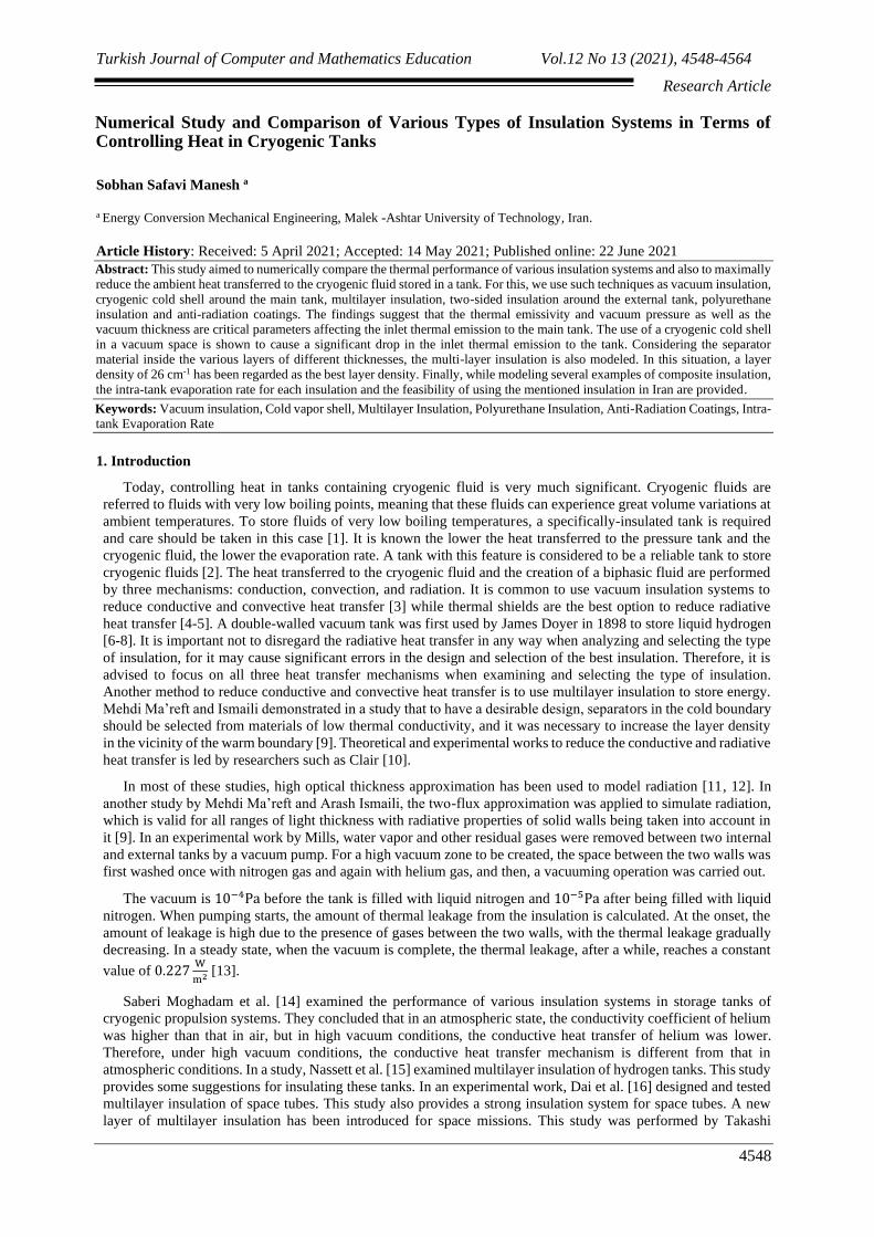
Figure 1: Schematic vacuum-insulated tank
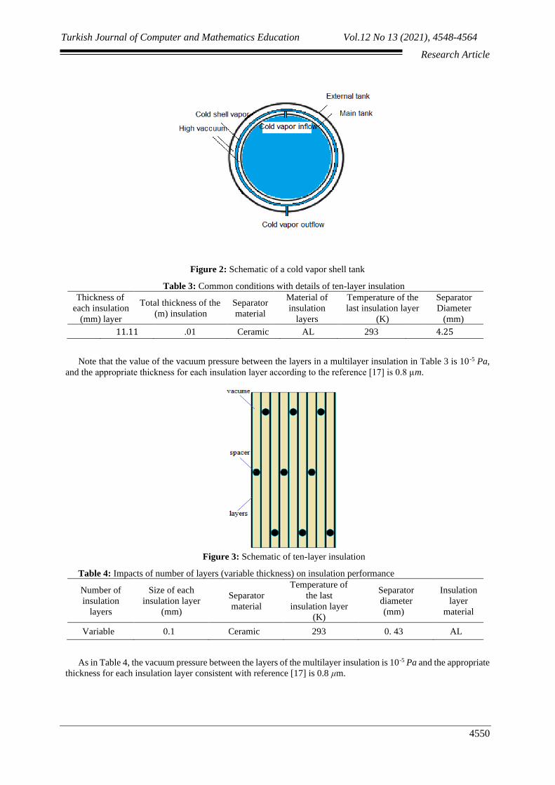
Table 2: Specifications of a cryogenic cold shell-insulated and vacuum-insulated tank
Size of each
vacuum layer (m)
Cold shell
thickness (m)
temperature of the
inlet vapors to the
shell (K)
Inlet flow rate vapor to
the shell
(𝑘𝑔/s)
Vacuum
pressure
(Pa)
0.03 0.05 85 0.00002 10−5
Turkish Journal of Computer and Mathematics Education Vol.12 No 13 (2021), 4548-4564
Research Article
4550
Figure 2: Schematic of a cold vapor shell tank
Table 3: Common conditions with details of ten-layer insulation
Thickness of
each insulation
layer (mm)
Total thickness of the
insulation (m)
Separator
material
Material of
insulation
layers
Temperature of the
last insulation layer
(K)
Separator
Diameter
(mm) 11.11 .01 Ceramic AL 293 4.25
Note that the value of the vacuum pressure between the layers in a multilayer insulation in Table 3 is 10 -5 Pa,
and the appropriate thickness for each insulation layer according to the reference [17] is 0.8 μm.
Figure 3: Schematic of ten-layer insulation
Table 4: Impacts of number of layers (variable thickness) on insulation performance
Number of
insulation
layers
Size of each
insulation layer
(mm)
Separator
material
Temperature of
the last
insulation layer
(K)
Separator
diameter
(mm)
Insulation
layer
material
Variable 0.1 Ceramic 293 0. 43 AL
As in Table 4, the vacuum pressure between the layers of the multilayer insulation is 10-5 Pa and the appropriate
thickness for each insulation layer consistent with reference [17] is 0.8 μm.

Turkish Journal of Computer and Mathematics Education Vol.12 No 13 (2021), 4548-4564
Research Article
4551
Figure 4: Model geometry for Table 4
Table 5: Impacts of the number of layers (constant thickness) on insulation performance
Number of
layers in a
constant
thickness (m)
Total
insulatio
n size
(m)
Separator
material
Temperature
of the last
layer of
insulation (K)
Separator
diameter
(m)
Material of
insulation layers
Variable .01 Ceramic 293 .00043 AL
2-2 Ambient conditions (cylindrical tank)
Reference [14] demonstrates the emissivity of 304 stainless steel and aluminum at different temperatures. In
Tables 6, 7 and 8, the material of the main and the external tank is 304 stainless steel. The vacuum pressure used
is also 10-4 Pa.
Table 6: Features and boundary conditions of the vacuum-insulated tank
Ambient
temperature
(K)
Ambient convective
heat transfer
coefficient (𝑊
𝐾.𝑚2)
Internal wall
absorption
coefficient
External wall
absorption
coefficient
Vacuum
insulation
thickness (m)
293 10 .023 .017 Variable
Table 7: Use of polyurethane and anti-radiation insulations around the external tank
Reflective
insulation
absorption
coefficient
Thermal
conductivity
coefficient of
the last
layer(𝑊
𝑚.𝐾)
Size of each
vacuum
insulation
layer (m)
Ambient
temperature
(K)
Ambient
convective
heat transfer
coefficient
(𝑊
𝐾.𝑚2)
Internal wall
absorption
coefficient
External
wall
absorption
coefficient
Thickness
of the last
insulation
layer (m)
.05 .03 .09 293 10 . 13 . 17 .01
Turkish Journal of Computer and Mathematics Education Vol.12 No 13 (2021), 4548-4564
Research Article
4552
Figure 5: Geometry of insulation used in Table 7
Table 8: Use of combined vacuum, cold shell vapor vacuum and of two-sided insulation techniques around the
main tank
Thickness
of each
vacuum
insulation
layer (m)
Anti-
radiation
absorption
coefficient
Absorption
coefficient
of external
foam with
reflective
coating
Thermal
conductivity
coefficient of
the internal
foam layer𝑊
𝑚.𝐾
Thermal
conductivity
coefficient of
the external
foam layer𝑊
𝑚.𝐾
Thickness
of the
internal
foam
layer(m)
Thickness
of the
external
foam layer
(m)
Thickness
of cold
vapor shell
(m)
.03 .05 .023 .03 .04 .01 .015 .03
The convective heat transfer coefficient and ambient temperature are provided as in Table 8. It is also assumed
that the temperature of the inlet vapors to the shell is 85°K and the inlet flow rate is 0.00002 kg/s. A temperature
of 85 °K is used consistent with reference [14].
3- Numerical solution method
The available equations are solved numerically using Ansys Fluent software based on finite volume method.
The second-order forward equations are explicitly used to solve the energy equation. Symmetry conditions have
been used to reduce the computational costs. The output results for thermal emission take the form of w
𝑚2 which
can be independently used of the tank geometry. In this study, the convergence criterion is shown to be 10 -6. The
surface-to-surface model is used to model the radiation and the Boussinesq’s model to apply the free (natural)
convection outside the tank.
4- Grid independence
Several elements are studied to examine the grid independence.
Table 6: Grid independence results for vacuum insulation with a thickness of .09m
Grid Total inlet heat to the main tank (𝑤
𝑚2)
1 29943 14.951
2 48808 15.451
4 65326 16.951
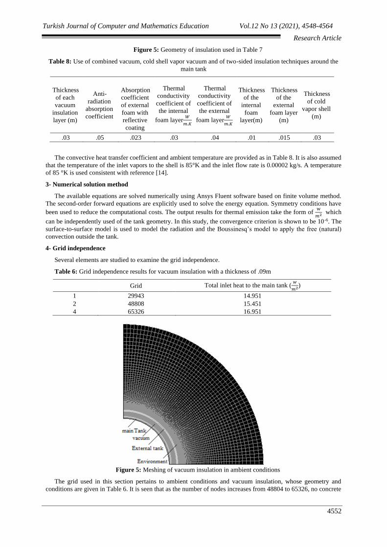
Figure 5: Meshing of vacuum insulation in ambient conditions
The grid used in this section pertains to ambient conditions and vacuum insulation, whose geometry and
conditions are given in Table 6. It is seen that as the number of nodes increases from 48804 to 65326, no concrete
Turkish Journal of Computer and Mathematics Education Vol.12 No 13 (2021), 4548-4564
Research Article
4553
changes in the results are noted. Therefore, to avoid wasting time and reduce costs, 48,804 nodes are considered
to be the final analysis (Table 11).
5- Results validation
5-1: Validation of non-insulated tank results
To validate the inlet thermal emission to the internal wall, we use the Fourier heat conduction law for the
conditions in Table 1. In the meantime, the external wall temperature of 293°K and the internal wall temperature
of 77°K were validated. the Fourier heat conduction law for a spherical tank is according to 𝐪 =𝟒𝛑𝐤∆𝐓
(𝟏
𝐫𝟏−
𝟏
𝐫𝟐). Fourier
heat conduction law yields a thermal emission of 559220.52 W to the tank.
Table 12: Results validation for non-insulated tank (Specifications are provided in Table 1)
Exte Inte Mo Fou E
mal | mal del rier rr
wall wall ing res 0
tem tem res ult r
pera pera ults (K) )
ture ture (W %
(K) (K) )
(
60 559
293 77 02
67.
1
6.
8 220
.55
5-2: Validation of vacuum insulation results
At cryogenic temperatures, even if a vacuum system is available, heat is again transferred by the radiative
mechanism and is significant. The rate of radiative heat transfer between the surfaces of two concentric bodies
without an interference of any material is obtained from Equation 12 [14].
𝑄𝑟 = .53 ∗ 10−8 (𝑤
𝑘. 𝑓𝑡2) ∗
𝑒1𝑒2
𝑒2 +𝐴1
𝐴2(1 − 𝑒2)𝑒1
× (𝑻𝟐𝟒 − 𝑻𝟏
𝟒)𝑨𝟏
In equation 12, Qr is the radiative heat transfer rate in watts, e1 the internal surface emissivity, e2 is the external
surface emissivity whose value varies according to the material and surface temperature, T1 is the internal surface
temperature, T2 is the external surface temperature in Kelvin, A1 internal tank area and A2 external tank area in
terms of ft2. Table 13 provides the results for insulation with a thickness of 8 cm (thermal radiation imparted to the
external wall of the internal tank).
Table 13: Validation of results for 8cm thick insulation
Internal tank
material
Internal tank
temperature (K)
Main tank
temperature (K)
Radiation for
simulation (W)
Radiation for
equation 12(W)
error
)%(
Aluminum-
coated steel 293 77 27.5 29.01 5.1
In reference [14], the emissivity of 304 stainless steel and aluminum at different temperatures are given. Internal
and external tank radii are adopted as .51m and .59m, respectively.

Turkish Journal of Computer and Mathematics Education Vol.12 No 13 (2021), 4548-4564
Research Article
4554
5-3: Validation of multilayer-insulated tank results
In the first stage, modeling of the aluminum-made ten-layer insulation with a total thickness of one centimeter
has been used for validation as demonstrated in Table 4. We consider a ten-layer insulation with the conditions in
Table 4, the geometry of which is illustrated in Figure 2. In this section, the results of ten-layer insulation are
validated by laboratory findings. Note that the diameter of retaining material and the thickness of the layers is used
in line with the standards used in credible articles. Table 14 compares the simulation results with the laboratory
findings found by Peng Li and Huier Cheng [19]. Figure 6 illustrates the temperature distribution in this ten-layer
insulation.
Figure 6: Temperature distribution for ten-layer insulation
Table 14: Comparison of simulation results with laboratory findings (Peng Li and Huier Cheng) for ten-layer
insulation
Thermal conductivity for
simulation (w)
Thermal conductivity for laboratory
results (W)
Error
)%(
0.118 0.11 6.7
6- Discussing the results
6-1- Spherical tank
6-1-1- Results for non-insulated tank
The thermal emission imparted to the internal wall of the tank by thermal conductivity is 600267.1 watts. Note
that we used constant temperature conditions for analysis with the convective heat transfer not considered. The
boundary conditions are provided in Table 1. Because the temperature of vapors and liquids inside the tank are
equal, it provides symmetrical and constant temperature conditions for the wall and constant temperature
conditions can yield a good approximation.
6-2: Vacuum insulation to reduce conductive heat transfer to the tank
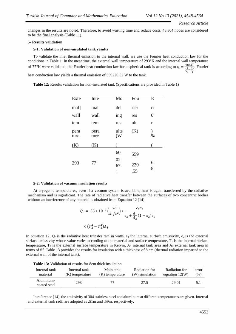
Citing Table 2 and Figure 1, the results for vacuum insulation are provided. Figure 7 illustrates the heat emission
to the internal tank. Both tanks in this state are made of 304 stainless steel. Increased vacuum thickness can reduce
the conductive heat transfer. Because the surface of the two tanks has increased along with increased vacuum
insulation thickness, the amount of radiative heat transfer increases also. Figure 8 demonstrates the thermal
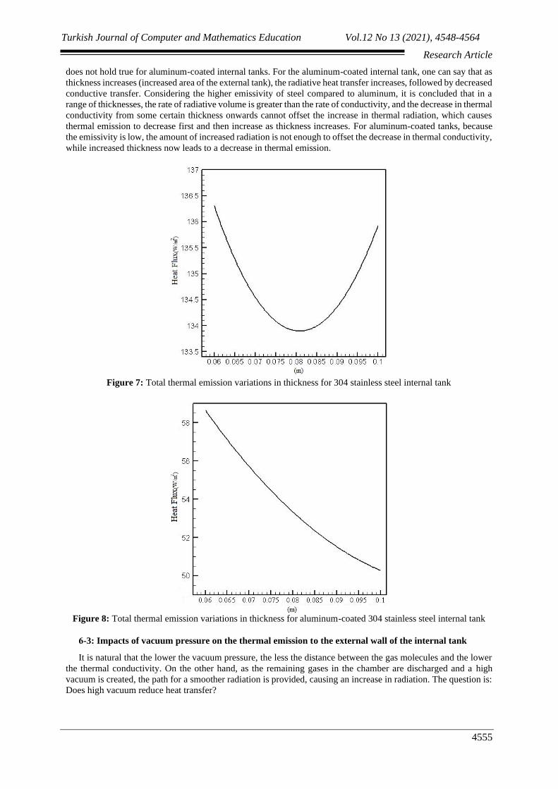
emission of vacuum insulation to the internal tank of aluminum-coated 304 stainless steel and the external tank of
304 stainless steel. Adding a coating of aluminum with a lower emissivity causes a more significant drop in
radiation. Increased thickness of the vacuum insulation (increased surface area of the external tank) reduces the
conductive heat transfer, on the one hand, and increases the radiative heat transfer, on the other. For an internal
tank of stainless steel, the total heat transfer decreases and then increases as the thickness increases. However, this
Turkish Journal of Computer and Mathematics Education Vol.12 No 13 (2021), 4548-4564
Research Article
4555
does not hold true for aluminum-coated internal tanks. For the aluminum-coated internal tank, one can say that as
thickness increases (increased area of the external tank), the radiative heat transfer increases, followed by decreased
conductive transfer. Considering the higher emissivity of steel compared to aluminum, it is concluded that in a
range of thicknesses, the rate of radiative volume is greater than the rate of conductivity, and the decrease in thermal
conductivity from some certain thickness onwards cannot offset the increase in thermal radiation, which causes
thermal emission to decrease first and then increase as thickness increases. For aluminum-coated tanks, because
the emissivity is low, the amount of increased radiation is not enough to offset the decrease in thermal conductivity,
while increased thickness now leads to a decrease in thermal emission.
Figure 7: Total thermal emission variations in thickness for 304 stainless steel internal tank
Figure 8: Total thermal emission variations in thickness for aluminum-coated 304 stainless steel internal tank
6-3: Impacts of vacuum pressure on the thermal emission to the external wall of the internal tank
It is natural that the lower the vacuum pressure, the less the distance between the gas molecules and the lower
the thermal conductivity. On the other hand, as the remaining gases in the chamber are discharged and a high
vacuum is created, the path for a smoother radiation is provided, causing an increase in radiation. The question is:
Does high vacuum reduce heat transfer?

Turkish Journal of Computer and Mathematics Education Vol.12 No 13 (2021), 4548-4564
Research Article
4556
Figure 9: Radiative and conductive thermal emission imparted to the external wall of the internal tank in watts
for various vacuum pressures
Figure 9 illustrates the radiative and conductive thermal emission for three different pressures. It is clear that
as the vacuum pressure decreases, the conductive heat transfer decreases while the radiative heat transfer increases
slightly. It is important to note that the rate of decrease in thermal conductivity is higher than the increase in
radiation, and generally, a decrease in vacuum pressure is followed by a decrease in heat transfer imparted to the
tank.
6-4: Cryogenic cold shell insulation around the main tank to reduce radiative heat transfer
Here, in this stage, the main tank, instead of exchanging heat in a direct exchange with the ambient, does this
via a cold shell. By coating the main tank with shell nitrogen and liquid oxygen, the insulated walls are cooled for
about 85°K, reducing radiative heat transfer. Using this type of insulation system causes almost all the heat at room
temperature emitted from the surface to evaporate the liquid oxygen, reducing the total heat emission imparted to
the tank by 245 w/m2. The conditions stated in Table 3 and Figure 1 are used for insulation. Two vacuum insulation
layers are used to reduce conductive and convective heat transfer, and using liquid oxygen shell is to reduce
radiative heat transfer. In this method, we suppose that the cryogenic cold shell temperature remains constant. For
this end, cryogenic cold vapors inside the tank are conducted into the cold shell through tubes as this cold vapor
takes some radiative and conductive energy which is sent to a chamber for liquefaction by a pump. After
liquefaction, oxygen will be returned to the main tank.
6-5: Multi-layer thermal insulations to reduce conductive and radiative heat transfer
6-5-1: Impacts of number of layers (Variable thickness) on insulation performance
The main goal is to examine the number of layers on the thermal flux and temperature profile. The boundary
conditions and data taken for the simulation are provided in Table 5 and Figure 3. Increased number of layers
causes the radiation imparted to the cold part of the tank to come down; on the other hand, as the number of layers
increase, heat arises outside the tank in areas farther from the cold area, contributing to reducing heat transfer
through conductivity. Table 15 illustrates the thermal emissions imparted to the cold parts for the insulation
mentioned. It is noted that as the number of layers increase, the total thermal emission imparted to the tank
decreases while the insulation thickness increases.
Table 15: Thermal emissions to the cold part of the tank
Number of layers Total insulation thickness
(M)
Main tank thermal emission
(𝑤
𝑚2)
3 0.0002242 10.25
4 0.0003363 7.15
5 0.0004484 5.45
6
7
0.0005605
0.0006726
3.21
2.61
6-5-2: Impacts of number of layers (Constant thickness) on insulation performance
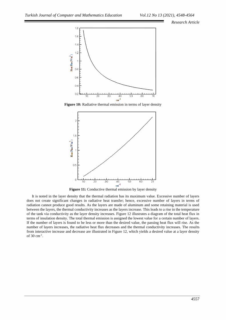
Diagrams in Figures 10 and 11 demonstrate conductive and radiative thermal emissions by layer density. It is
noted that as layer density increases, the passing radiative layer decreases, but conversely, thermal conductivity
increases. An increase in the number of layers helps these layers act as heat shields against radiation and thus
reduce radiative heat emission.
Turkish Journal of Computer and Mathematics Education Vol.12 No 13 (2021), 4548-4564
Research Article
4557
Figure 10: Radiative thermal emission in terms of layer density
Figure 11: Conductive thermal emission by layer density
It is noted in the layer density that the thermal radiation has its maximum value. Excessive number of layers
does not create significant changes in radiative heat transfer; hence, excessive number of layers in terms of
radiation cannot produce good results. As the layers are made of aluminum and some retaining material is used
between the layers, the thermal conductivity increases as the layers increase. This leads to a rise in the temperature
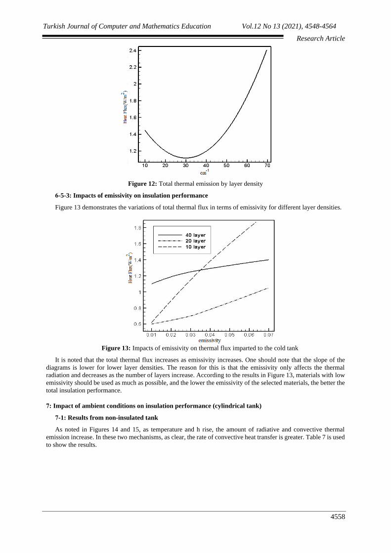
of the tank via conductivity as the layer density increases. Figure 12 illustrates a diagram of the total heat flux in
terms of insulation density. The total thermal emission is assigned the lowest value for a certain number of layers.
If the number of layers is found to be less or more than the desired value, the passing heat flux will rise. As the
number of layers increases, the radiative heat flux decreases and the thermal conductivity increases. The results
from interactive increase and decrease are illustrated in Figure 12, which yields a desired value at a layer density
of 30 cm-1.
Turkish Journal of Computer and Mathematics Education Vol.12 No 13 (2021), 4548-4564
Research Article
4558
Figure 12: Total thermal emission by layer density
6-5-3: Impacts of emissivity on insulation performance
Figure 13 demonstrates the variations of total thermal flux in terms of emissivity for different layer densities.
Figure 13: Impacts of emissivity on thermal flux imparted to the cold tank
It is noted that the total thermal flux increases as emissivity increases. One should note that the slope of the
diagrams is lower for lower layer densities. The reason for this is that the emissivity only affects the thermal
radiation and decreases as the number of layers increase. According to the results in Figure 13, materials with low
emissivity should be used as much as possible, and the lower the emissivity of the selected materials, the better the
total insulation performance.
7: Impact of ambient conditions on insulation performance (cylindrical tank)
7-1: Results from non-insulated tank
As noted in Figures 14 and 15, as temperature and h rise, the amount of radiative and convective thermal
emission increase. In these two mechanisms, as clear, the rate of convective heat transfer is greater. Table 7 is used
to show the results.

Turkish Journal of Computer and Mathematics Education Vol.12 No 13 (2021), 4548-4564
Research Article
4559
Figure 14: Variations of convective heat transfer imparted to the internal wall of a non-insulated tank by
temperature variations at different h states
Figure 15: Variations of radiative heat transfer imparted to the internal wall of a non-insulated tank in terms
of temperature variations at different h states
7-2: Vacuum-insulated tank results
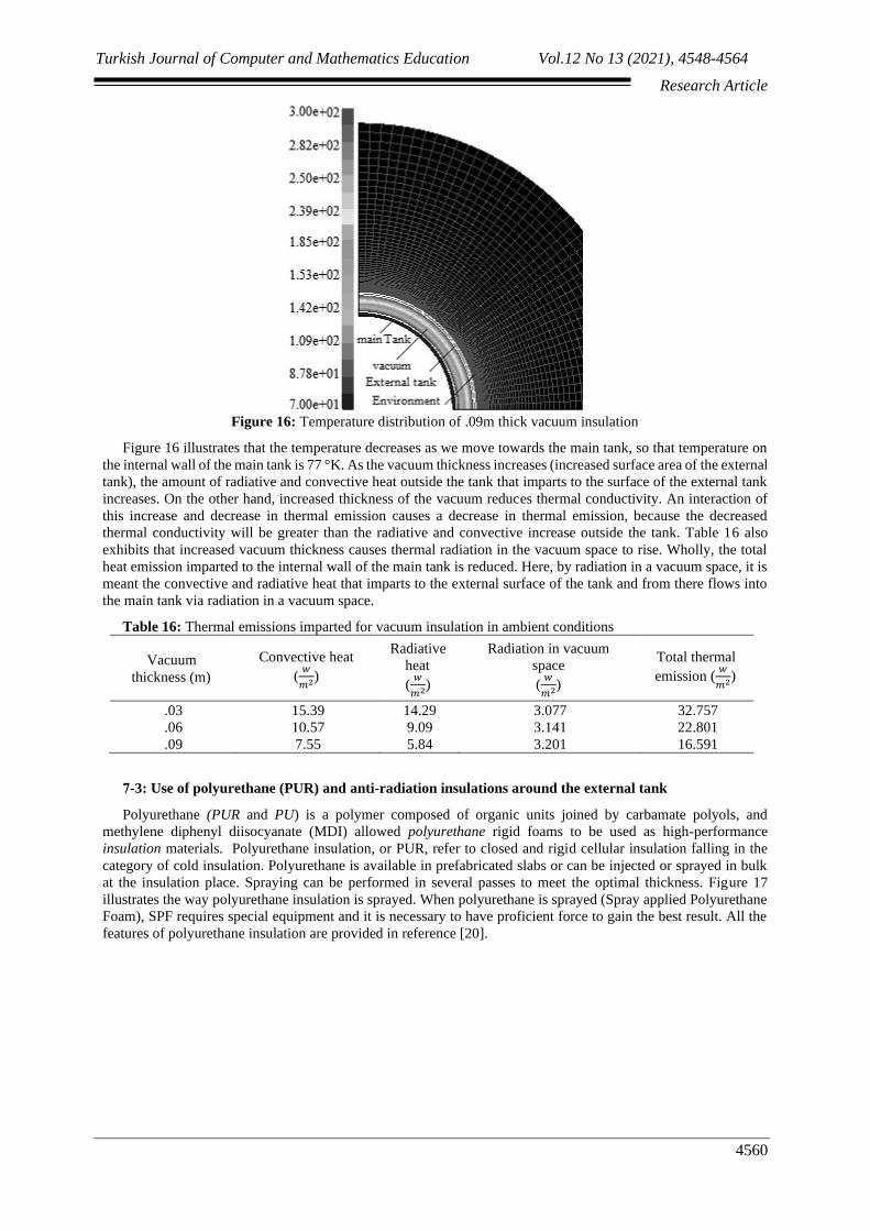
Figure 16 demonstrates the temperature distribution of a .09m thick vacuum insulation. The ambient
temperature, as seen in the figure, has a maximum value of about 293°K.
Turkish Journal of Computer and Mathematics Education Vol.12 No 13 (2021), 4548-4564
Research Article
4560
Figure 16: Temperature distribution of .09m thick vacuum insulation
Figure 16 illustrates that the temperature decreases as we move towards the main tank, so that temperature on
the internal wall of the main tank is 77 °K. As the vacuum thickness increases (increased surface area of the external
tank), the amount of radiative and convective heat outside the tank that imparts to the surface of the external tank
increases. On the other hand, increased thickness of the vacuum reduces thermal conductivity. An interaction of
this increase and decrease in thermal emission causes a decrease in thermal emission, because the decreased
thermal conductivity will be greater than the radiative and convective increase outside the tank. Table 16 also
exhibits that increased vacuum thickness causes thermal radiation in the vacuum space to rise. Wholly, the total
heat emission imparted to the internal wall of the main tank is reduced. Here, by radiation in a vacuum space, it is
meant the convective and radiative heat that imparts to the external surface of the tank and from there flows into
the main tank via radiation in a vacuum space.
Table 16: Thermal emissions imparted for vacuum insulation in ambient conditions
Vacuum
thickness (m)
Convective heat
(𝑤
𝑚2)
Radiative
heat
(𝑤
𝑚2)
Radiation in vacuum
space
(𝑤
𝑚2)
Total thermal
emission (𝑤
𝑚2)
.03 15.39 14.29 3.077 32.757
.06 10.57 9.09 3.141 22.801
.09 7.55 5.84 3.201 16.591
7-3: Use of polyurethane (PUR) and anti-radiation insulations around the external tank
Polyurethane (PUR and PU) is a polymer composed of organic units joined by carbamate polyols, and
methylene diphenyl diisocyanate (MDI) allowed polyurethane rigid foams to be used as high-performance
insulation materials. Polyurethane insulation, or PUR, refer to closed and rigid cellular insulation falling in the
category of cold insulation. Polyurethane is available in prefabricated slabs or can be injected or sprayed in bulk
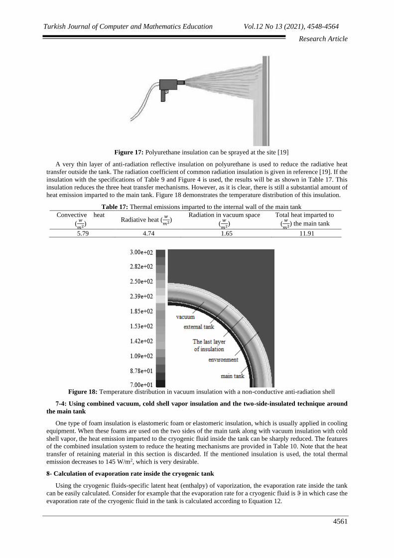
at the insulation place. Spraying can be performed in several passes to meet the optimal thickness. Figure 17
illustrates the way polyurethane insulation is sprayed. When polyurethane is sprayed (Spray applied Polyurethane
Foam), SPF requires special equipment and it is necessary to have proficient force to gain the best result. All the
features of polyurethane insulation are provided in reference [20].
Turkish Journal of Computer and Mathematics Education Vol.12 No 13 (2021), 4548-4564
Research Article
4561
Figure 17: Polyurethane insulation can be sprayed at the site [19]
A very thin layer of anti-radiation reflective insulation on polyurethane is used to reduce the radiative heat
transfer outside the tank. The radiation coefficient of common radiation insulation is given in reference [19]. If the
insulation with the specifications of Table 9 and Figure 4 is used, the results will be as shown in Table 17. This
insulation reduces the three heat transfer mechanisms. However, as it is clear, there is still a substantial amount of
heat emission imparted to the main tank. Figure 18 demonstrates the temperature distribution of this insulation.
Table 17: Thermal emissions imparted to the internal wall of the main tank
Convective heat
(𝑤
𝑚2) Radiative heat (
𝑤
𝑚2) Radiation in vacuum space
(𝑤
𝑚2)
Total heat imparted to
the main tank (𝑤
𝑚2)
5.79 4.74 1.65 11.91
Figure 18: Temperature distribution in vacuum insulation with a non-conductive anti-radiation shell
7-4: Using combined vacuum, cold shell vapor insulation and the two-side-insulated technique around
the main tank
One type of foam insulation is elastomeric foam or elastomeric insulation, which is usually applied in cooling
equipment. When these foams are used on the two sides of the main tank along with vacuum insulation with cold
shell vapor, the heat emission imparted to the cryogenic fluid inside the tank can be sharply reduced. The features
of the combined insulation system to reduce the heating mechanisms are provided in Table 10. Note that the heat
transfer of retaining material in this section is discarded. If the mentioned insulation is used, the total thermal
emission decreases to 145 W/m2, which is very desirable.
8- Calculation of evaporation rate inside the cryogenic tank
Using the cryogenic fluids-specific latent heat (enthalpy) of vaporization, the evaporation rate inside the tank
can be easily calculated. Consider for example that the evaporation rate for a cryogenic fluid is ϑ in which case the
evaporation rate of the cryogenic fluid in the tank is calculated according to Equation 12.

Turkish Journal of Computer and Mathematics Education Vol.12 No 13 (2021), 4548-4564
Research Article
4562
evaporation rate =Q(W)
ϑ(J
kg) (12)
Using the unit conversion W =𝐽
𝑠, Equation 12 becomes
kg
s, suggesting that how many kilograms of cryogenic
fluid is converted to vapor each second. To convert to kg
day, it suffices to multiply the resulting expression by
3600*24 to calculate the evaporation rate in the cryogenic tank. Thus, we use Equation 13 to calculate the
evaporation rate of cryogenic tank by kg
day.
evaporation rate =Q(W)
ϑ(J
kg)
∗ 3600 ∗ 24 (13)
Generally speaking, the amount and performance of an appropriate insulation system in cryogenic applications
are determined based on the percentage of evaporation of cryogenic material stored in the day. It is clear that in an
equal tank volume, the lower the percentage of evaporation rate of cryogenic material, the higher the performance
of the cryogenic insulation. Tables 23 and 24 demonstrate the impacts of various insulation systems on the
evaporation rate of different cryogenic fluids. Cold shell vapor insulation combined with other insulations yield
lower evaporation rate relative to other methods. Multilayer insulation also produces a small percentage of vapor
each day, suggesting its high performance. The evaporation rate for liquid helium is greater than those of other
cryogenic fluids and care should be taken when insulating these tanks. The reason for this is the low latent heat of
evaporation of this liquid compared to other cryogenic fluids.
Table 23: Comparison of evaporation rate in spherical tank made of various insulations (constant temperature
conditions)
Insulation Helium
(𝑘𝑔
𝑑𝑎𝑦)
Hydrogen
(𝑘𝑔
𝑑𝑎𝑦)
Nitrogen
(𝑘𝑔
𝑑𝑎𝑦)
Oxygen
(𝑘𝑔
𝑑𝑎𝑦)
Non-insulated tank 2469658.1 - 116545.6 - 259314.05 - 243487.3 -
high vacuum 176.9 8.3 18.5 17.44
Vacuum with cold vapor shield 14.4 .68 1.51 1.41
Multi-layer with high vacuum 21.6 1.01 2.27 2.12
Table 23: Comparison of evaporation rate in a cylindrical tank of various insulations (ambient conditions)
Insulation Helium
(𝑘𝑔
𝑑𝑎𝑦)
Hydrogen
(𝑘𝑔
𝑑𝑎𝑦)
Nitrogen
(𝑘𝑔
𝑑𝑎𝑦)
Oxygen
(𝑘𝑔
𝑑𝑎𝑦)
Non-insulated tank 216645.5 - 1022.3 2274.7 2135.9
high vacuum 67.8 3.2 7.1 6.7
Vacuum with cold vapor shield 9.91 .46 1. 1 0.97
Multi-layer with high vacuum 48.9 2.3 5.1 4.8
9: Conclusion
The results of the present study are generally summarized as follows.
➢ In vacuum insulation, increased thickness on the one hand reduces the conductive heat transfer, and on the
other hand, increases the radiative heat transfer. For the main stainless-steel tank, as thickness increases,
the total heat transfer decreases and then increases. This is while, with regards to the main aluminum-
coated tank, since the emissivity is low, the rate of radiation is not enough to yield an unexpected outcome,
and we always see reduced heat transfer to the main tank as thickness increases.
➢ In vacuum-insulated systems, the lower the vacuum pressure, the less the distance between the gas
molecules and the lower the thermal conductivity.
➢ Applying vapor from liquid evaporation inside the tank and conducting it through tubes around the main
tank is another technique to reduce radiative heat transfer in tanks containing cryogenic fluids. In this
situation, the main tank, instead of exchanging heat in a direct exchange with the ambient, does this via a
cold shell.
➢ A very thin layer of anti-radiation reflective insulation on polyurethane was been used to reduce the
radiative heat transfer outside the tank.
Turkish Journal of Computer and Mathematics Education Vol.12 No 13 (2021), 4548-4564
Research Article
4563
➢ Using multiple layers in a certain thickness will be very useful to reduce radiative and conductive heat. As
the layer density increases, the passing radiation decreases; however, the thermal conductivity increases.
The interactive increase and decrease are in the form of Figure (14-4), resulting in an optimal value in the
number of layers.
➢ As an important conclusion in a specific emissivity, two multi-layer insulations with several numbers of
layers may yield similar functions to each other. In this case, insulation with a low number of layers is
selected to reduce costs.
➢ Cold shell vapor insulation combined with other insulation systems has a lower evaporation rate relative
to other methods. Multilayer insulation also causes a low percentage of vapor per day, indicating a greater
performance.
➢ Evaporation rate of helium fluid is greater than those of other cryogenic fluids and care should be taken
when insulating these tanks. The reason for this is the low latent heat of evaporation of this fluid relative
to other cryogenic fluids.
➢ Concerning multi-layer and cold shell vapor insulation, using cutting edge technology and experienced
workforce is critical. Looking at the studies done and the existing capacities in the field of multilayer
insulation, it is not out of expectation to see this type of insulation being mass produced. If we manage to
bring this type of insulation to the production stage, high-vacuum multi-layer insulation can be proposed
as the best insulation system for cryogenic tanks.
10. Indices
𝑃 Pressure (kgm-1s-2)
𝐴1 Area ft2
∝𝟏 Accommodation coefficient
∝𝟐 Accommodation coefficient
𝑇 Mean temp. (K)
𝐶𝑃 Specific heat capacity (W/kg.K)
𝐶𝑣 Specific heat capacity (W/kg.K)
𝑇1 Internal surface temp(K)
𝑇2 External surface temp(K)
∆𝑇 temperature difference (K)
𝑄𝑟 Radiative heat transfer (W)
𝑒1 Emissivity
𝑒2 Emissivity
Greek sign
γ 𝐶𝑃
𝐶𝑉 ratio
References
[1] Babac, G., Sisman, A., & Cimen, T. (2009). Two-dimensional thermal analysis of liquid hydrogen tank
insulation. International journal of hydrogen energy, 34(15), 6357-6363.
[2] Aceves, S. M., Berry, G. D., Martinez-Frias, J., & Espinosa-Loza, F. (2006). Vehicular storage of hydrogen in
insulated pressure vessels. International Journal of Hydrogen Energy, 31(15), 2274-2283.
[3] Incropera, F. P. D. D. P. Introduction to Heat Transfer.
[4] Chato, D. J., Van Dyke, M., Batty, J. C., & Schick, S. (1998, January). Status and design concepts for the
hydrogen on-orbit storage and supply experiment. In AIP Conference Proceedings (Vol. 420, No. 1, pp. 276-
281). American Institute of Physics.
[5] Holman. J. P, (1989). Heat Transfer. Mcgraw-Hill, 676.
[6] Barron, R. (1966). Cryogenic Systems. new york: Louisiana Oolytechnic Institute.
[7] Toscano, W. M. R. F. C. (1980). Cryogenic Processes and Equipment in Energy Systems. The American society
of mechanical engineers.
[8] Kalanidhi, A. (1988). Boil-off in long-term stored liquid hydrogen. International journal of hydrogen energy,
13(5), 311-313.
[9] Mo'refat, M., Esmaili, A., (2014). Combined heat conductivity analysis of radiation conductivity in Chen Layer
insulation materials, Amirkabir Scientific Journal, 46(1), 47-56. (in Persian)
[10] Keller, K., Hoffmann, M., Zörner, W., & Blumenberg, J. (1992). Application of high temperature multilayer
insulations. Acta Astronautica, 26(6), 451-458.
Turkish Journal of Computer and Mathematics Education Vol.12 No 13 (2021), 4548-4564
Research Article
4564
[11] Grallert, H., & Keller, K. (1991). Metallic thermal protection concept for hypersonic vehicles. Journal of
Aircraft, 28(6), 410-416.
[12] Zhao, S. Y., Zhang, B. M., & He, X. D. (2009). Temperature and pressure dependent effective thermal
conductivity of fibrous insulation. International journal of thermal sciences, 48(2), 440-448.
[13] Mills, G. L., & Zeller, C. M. (2008, March). The performance of gas filled multilayer insulation. In AIP
Conference Proceedings (Vol. 985, No. 1, pp. 1475-1482). American Institute of Physics.
[14] Sabery Moghadam, A., Ghasemi, Z., Jaefari, F., Nast, T.C., Frank, D.J., Fller, J. (2014). Multilayer insulation
considerations for large propellant tanks, Cryogenics. 64, 105-111.
[16] Dye, S. A., Tyler, P. N., Mills, G. L., & Kopelove, A. B. (2014). Wrapped multilayer insulation design and
testing. Cryogenics, 64, 100-104.
[17] Miyakita, T., Hatakenaka, R., Sugita, H., Saitoh, M., & Hirai, T. (2014). Development of a new multi-layer
insulation blanket with non-interlayer-contact spacer for space cryogenic mission. Cryogenics, 64, 112-120.
[18] Wang, L., Ma, Y., Wang, Y., Xie, F., & Li, Y. (2016). Investigation on pressurization behaviors of two-side-
insulated cryogenic tank during discharge. International Journal of Heat and Mass Transfer, 102, 703-712.
[19] Li, P., & Cheng, H. (2006). Thermal analysis and performance study for multilayer perforated insulation
material used in space. Applied thermal engineering, 26(16), 2020-2026.
[20] Iran Insulation Encyclopedia website / Thermal insulations / Polyurethane insulations (in Persian).