Numerical Simulation of Laminar Forced Convection of Pin ...Numerical Simulation of Laminar Forced...
23
Appl. Sci. 2015, 5, 1846-1868; doi:10.3390/app5041846 applied sciences ISSN 2076-3417 www.mdpi.com/journal/applsci Article Numerical Simulation of Laminar Forced Convection of Pin-Fin Heat-Sink Array in a Channel by Using Porous Approach Tzer-Ming Jeng and Sheng-Chung Tzeng * Department of Mechanical Engineering, Chienkuo Technology University, Changhua 500, Taiwan; E-Mail: [email protected] * Author to whom correspondence should be addressed; E-Mail: [email protected]; Tel.: +886-4-7111111 (ext. 3192); Fax: +886-4-7357193. Academic Editor: Chien-Hung Liu Received: 30 July 2015 / Accepted: 7 December 2015 / Published: 16 December 2015 Abstract: This work used a porous approach model to numerically investigate the fluid flow and heat transfer characteristics of the pin-fin heat-sink array in a rectangular channel with in-line arrangement. The air flow through the channel was laminar. The pin-fin heat sinks with various porosities and pin-fin numbers were employed. The relative center-to-center longitudinal and transverse distances between adjacent heat sinks were changed. The results indicate that the Nusselt number of various heat-sink arrays increased with decreasing the relative center-to-center transverse distance, but not varied with the relative center-to-center longitudinal distance. For the typical pin-fin heat-sink arrays, the Nusselt number changed slightly for the heat sinks with 0.358–0.556 porosity, but increased by 11.7%–24.8% when the porosity increased from 0.556 to 0.750, and then dropped obviously when the porosity exceeded 0.750. Increasing the number of pin fins continuously could increase Nusselt number. However, when the number of pin fins was large, the Nusselt number increased with the number of pin fins slowly. The present numerical simulation has been validated by the typical experiment. Finally, a semi-empirical correlation of Nusselt number for each heat sink in the heat-sink array was proposed. Keywords: porous approach; pin-fin heat sink; heat-sink array; heat transfer OPEN ACCESS
Transcript of Numerical Simulation of Laminar Forced Convection of Pin ...Numerical Simulation of Laminar Forced...

Appl. Sci. 2015, 5, 1846-1868; doi:10.3390/app5041846
applied sciences ISSN 2076-3417
www.mdpi.com/journal/applsci
Article
Numerical Simulation of Laminar Forced Convection of Pin-Fin Heat-Sink Array in a Channel by Using Porous Approach
Tzer-Ming Jeng and Sheng-Chung Tzeng *
Department of Mechanical Engineering, Chienkuo Technology University, Changhua 500, Taiwan;
E-Mail: [email protected]
* Author to whom correspondence should be addressed; E-Mail: [email protected];
Tel.: +886-4-7111111 (ext. 3192); Fax: +886-4-7357193.
Academic Editor: Chien-Hung Liu
Received: 30 July 2015 / Accepted: 7 December 2015 / Published: 16 December 2015
Abstract: This work used a porous approach model to numerically investigate the fluid
flow and heat transfer characteristics of the pin-fin heat-sink array in a rectangular channel
with in-line arrangement. The air flow through the channel was laminar. The pin-fin heat
sinks with various porosities and pin-fin numbers were employed. The relative
center-to-center longitudinal and transverse distances between adjacent heat sinks were
changed. The results indicate that the Nusselt number of various heat-sink arrays increased
with decreasing the relative center-to-center transverse distance, but not varied with the
relative center-to-center longitudinal distance. For the typical pin-fin heat-sink arrays, the
Nusselt number changed slightly for the heat sinks with 0.358–0.556 porosity, but
increased by 11.7%–24.8% when the porosity increased from 0.556 to 0.750, and then
dropped obviously when the porosity exceeded 0.750. Increasing the number of pin fins
continuously could increase Nusselt number. However, when the number of pin fins was
large, the Nusselt number increased with the number of pin fins slowly. The present
numerical simulation has been validated by the typical experiment. Finally, a
semi-empirical correlation of Nusselt number for each heat sink in the heat-sink array
was proposed.
Keywords: porous approach; pin-fin heat sink; heat-sink array; heat transfer
OPEN ACCESS

Appl. Sci. 2015, 5 1847
1. Introduction
Since the invention of integrated circuit (IC) in 1964, the speed of computers has rapidly increased.
As one IC can hold tens of electronic modules, the function of an electronic module is equivalent to a
transistor or vacuum tube, so that the computer becomes smaller and more powerful. At present, the IC
has evolved from early SSI (Small Scale Integrated Circuit, 10–100 modules/per unit chip) into LSI
(Large Scale Integrated Circuit, 1000–10,000 modules/per unit chip), then VLSI (Very Large Scale
Integrated Circuit, 100,000–1,000,000 modules/per unit chip), and finally even ULSI (Ultra Large
Scale Integrated Circuit, more than a million modules/per unit chip). Such a high density package of
semiconductor chip increases the heat density greatly, and the reliability or lifetime of semiconductor
chip decays as the temperature rises, usually in the range of below junction temperature 100 °C. A
lower temperature leads to a lower failure rate of the chip. Therefore, a good thermal control cooling
design is increasingly important for high-speed computer. Multilayer PCB substrate is mounted inside
general superhuge computer. Each PCB substrate is about tens of square centimeter, and carries a
hundred LSIs. The cooling technique is that the finned heat sink is mounted on the LSI chip for forced
air cooling. In such a configuration, there are gaps on both sides and top of the finned heat sink. A part
of forced cold flow enters the internal flow channels of heat sink for cooling, and a part of cold flow
leaves passing by the heat sink through the gaps. The bigger by-pass gap results in the smaller amount
of the effective cold flow through the heat sink, which is disadvantageous to the overall cooling of the
heat sink. Therefore, the by-pass gap and heat sink have optimal relative dimensions, so that there is
maximum cooling air entering into the heat sink at fixed pumping power. This is an important topic
considering actual forced air cooling.
The issue about the heat transfer characteristics of finned heat sinks without [1–6] or with bypass
effect [7–12] attracts wide attention continuously. This work is to discuss putting the pin-fin
heat-sink array into a rectangular channel in in-line arrangement with laminar side-bypass effect. This
configuration is similar to the PCB substrate of LSI array with heat sinks inside the general
supercomputer. Figure 1 shows the typical flow field of such cooling system with seven rows of heat
sinks. Considering the periodical and symmetric configuration of the present system, it only shows the
upper half of the single-column flow field. According to Figure 1, when the cold flow enters the heat
sink array, a part of fluid exchanges heat with the heat sink, and the other part of fluid passes by the
heat sink and passes through the gaps between adjacent heat-sink columns. The cold flow in the heat
sink leaks out of the heat sink from side continuously under the flow-resistance effect of pin-fins, so
that the downstream heat sink has less incoming cold flow. This phenomenon is especially obvious
when the permeability of heat sink is low, even forming recirculating flow between downstream heat
sinks. There is also a large recirculation zone behind the heat sink array. Such a change of flow field is
mainly related to the flow resistance of pin-fin heat sink and the relative spacing between heat sinks,
and affects the heat transfer characteristics of each heat sink significantly.

Appl. Sci. 2015, 5 1848
Figure 1. The upper half of the single-column flow field in seven-rows heat-sink array (the
direction of pin fins is pointing the Z-axis vertical to paper surface): (a) high-permeability
heat-sink array and (b) low-permeability heat-sink array.
In the numerical simulation of heat transfer and fluid flow characteristics of finned heat sink
without bypass effect, some studies regard the finned heat sink as a porous medium, using the
assumption of the volume-averaging technique for computations of the porous approach
model [13–17]. Besides, Jeng [18] used porous approach model to simulate the fluid flow and heat
transfer characteristics of single square pin-fin heat sink with laminar side-bypass effect. The
Brinkman-Forchheimer model was used for fluid flow and two-equation model for heat transfer.
Narasimhan et al. [19,20] numerically investigated the thermal behaviors of distributed porous blocks
in a channel by using a bi-disperse porous medium approach. They indicated that the Nusselt number
increasing with Reynolds number changed from non-linear to linear as number of blocks increased
from one to 81, with corresponding insignificant pumping power increase. Feng et al. [21] present a
porous medium model for forced air convection in pin/plate-fin heat sinks subjected to non-uniform
heating of an impinging jet. The forced convection is considered by employing the non-Darcy model
for fluid flow and the thermal non-equilibrium model for heat transfer. They showed that the inline
square pin-fin heat sink has topological advantage over the plate-fin heat sink, although the heat
spreading through the plate-fins on reducing the peak temperature on the substrate is pronounced.
The current study extends the porous approach simulation method discussed in the previous
study [18] to simulate the hydrodynamic and thermal behaviors of the pin-fin heat-sink array situated in a
rectangular channel in an in-line arrangement with various longitudinal and transverse distances
between heat sinks. The in-line pin-fin arrays of the heat sinks with various porosities and numbers of
pin fins, confined uniformly within a square spreader whose side length is 67 mm, were employed. In
the current study, the effects of various parameters, such as the porosity of heat sink, the number of pin
fins and the relative longitudinal and transverse distances between heat sinks, on the fluid flow and
heat transfer were analyzed.

Appl. Sci. 2015, 5 1849
2. Numerical Method
As the above-mentioned statement, this study uses the porous approach method proposed by
Jeng [18] to simulate the fluid flow and heat transfer characteristics of multiple pin-fin heat sinks
situated in a rectangular channel in an in-line arrangement similar to the PCB substrate of LSI array
with heat sinks. In general, side-bypass and top-bypass flows exist in such issue at the same time.
However, this work discusses the extreme configuration without any top-pass space above the
heat-sink array. Figure 2a describes the corresponding physical configurations for the present and
previous [18] studies, respectively. The previous study [18] only investigated the single pin-fin heat
sink situated in a rectangular channel with laminar side-bypass flow. The originality and contribution
of this work are to show the difference between single and array of pin-fin heat sink and the relevant
hydrodynamic and thermal behaviors of the downstream heat sinks. Because the present study only
considers the side-pass effect, it can be simplified to be two-dimensional problem with the assumption
of ignoring the 3D vortex flow around the roots of pin fins. Furthermore, for the present in-line
heat-sink array, each heat sink is responsible for cooling its corresponding bottom heat source. The
heat flux is firstly transmitted upwards through the pin fins by heat conduction, and then transmitted to
the air passing through the heat sink from the extended surface of the pin fins by heat convection. This
work sets each pin-fin heat sink as a porous-medium block. Since that this work has been treated as a
2D issue, the heat dissipated from pin fins is regarded as the heat generated in the solid matrix of the
porous block. Figure 2b shows the 2D configuration (x–y plane) cut from the middle of pin fins. The
top view of multiple pin-fin heat sinks with in-line arrangement is presented. The center-to-center
longitudinal and transverse distances (SL* and ST
*) between the adjacent heat sinks are variable.
Figure 2a also displays the 3D configuration of a typical pin-fin heat sink. The center-to-center
longitudinal distance between the adjacent pin-fins is SL, the center-to-center transverse distance is ST,
the number of pin-fins is n, the thickness of each square pin-fin is d, the size of pin-fin heat sink is
L × L × H, and the height of the channel is H. Other assumptions are as follows: (1) the porous
medium is homogenous and isotropic; (2) the fluid flow is steady state, laminar and incompressible;
and (3) the thermophysical properties of the fluid and porous media do not depend on temperature. The
dimensionless volume-averaged governing equations, including the Brinkman-Forchheimer model for
momentum equation and two-equation model for energy equations, can be expressed as follows [18].
2 2
2 2
Ψ Ψω
X Y
∂ ∂− = +∂ ∂
(1)
22 εω ω εω ω
ReF MC U
U VX Y Da Da
∂ ∂+ = − −∂ ∂ ⋅
2 2 2
2 2
ε ε ω ω( ) ( )
ReF M MC U U
U VY X X YDa
∂ ∂ ∂ ∂+ − + +∂ ∂ ∂ ∂
(2)
* 2 2
2 2
θ θ θ θ1(θ θ ) ( )
Re Pr Re Prf f fs f f f
s ff
Nu kU V
X Y k X Y
∂ ∂ ∂ ∂+ = − + +
∂ ∂ ⋅ ⋅ ∂ ∂ (3)
* 2 2
2 2
θ θ0 (θ θ ) ( ) δs s s
fs f sf
kNu
k X Y
∂ ∂= − + + +∂ ∂
(4)
and the relevant dimensionless parameters are as follows:

Appl. Sci. 2015, 5 1850
H
xX = ,
H
yY = ,
iu
uU = ,
iu
vV = ,
μ / ρPr
/ (ρ )f
f p fk C= ,
2H
KDa = ,
ρRe
μf iu H
= , i
M u
vuU
22 += , θ/
i
w f
T T
q H k
−= , 2
fs fsfs
f
h a HNu
k=
(5)
where H is the channel (or pin-fin) height, K is the permeability; afs is the surface area of the
fluid-solid interface per unit bulk volume of the pin-fin heat sink; hfs is the heat transfer coefficient
between the fluid stream and the solid matrix; qw is the heat flux on the bottom of the pin-fin heat sink;
ω is the vorticity, and ψ is the stream function.
ωU V
Y X
∂ ∂= − +∂ ∂
, Ψ
UY
∂=∂
, Ψ
VX
∂= −∂
(6)
In Equations (1)–(4), CF is the inertial coefficient; ε is the porosity of the pin-fin heat sink
(i.e., the total void volume divided by the total volume occupied by the pin fins and the void volume);
ks* is the effective conductivity of the solid matrix; and kf
* is the effective conductivity of the fluid.
Notably, in the clear fluid region, Da is set to infinity and ε to unity. In addition, Nufs = ks* = 0 and
kf* = kf. The δ is a function set equal to one to account for heat generation in the porous media of pin-fins
and to zero elsewhere.
Figure 2. Physical configuration: (a) 3D configurations (left: present study; right: previous
study [18]); and (b) 2D configuration (x–y plane) cut from the middle of fins.

Appl. Sci. 2015, 5 1851
The relevant empirical coefficients in the present porous medium of pin-fins, such as K, CF, ks*,
kf* and hfs, generally do not have universal values. This work lists the porous properties of pin-fin
heat sinks studied herein in Table 1 by using the relevant empirical formula reported in the open
literatures [18,22,23]. Some heat sinks in the present study are the same as those used in previous
study [18]. This is for verification purposes since the single heat sink in the previous study [18] might
be like the first row of heat sinks in the present study. The hfs of the square pin-fin heat sink with
uniform in-line arrangement is predicted by employing the empirical equations suggested by
Kim et al. [24]:
( )0.54219ε0.36283Ref
fs d
kh
d= for Red < 1000 (7)
( )0.82934ε0.04433Ref
fs d
kh
d= for Red ≥ 1000 (8)
where Red is defined as ρfumaxd/μ; umax is the average maximum velocity between pin-fins, and d is the
pin-fin thickness.
Table 1. Porous properties of pin-fin heat sinks used herein.
In-Line Square Pin-Fin Heat Sink with Uniform Distributions (SL = ST), L = 0.067 m, H = 0.0237 m
Test Specimens Sample 1 Sample 2 Sample 3 Sample 4 Sample 5 Sample 6 Sample 7 Sample 8
d (m) 0.00596 0.00496 0.00372 0.00479 0.0067 0.00298 0.00248 0.00305
n 9 × 9 9 × 9 9 × 9 7 × 7 5 × 5 9 × 9 9 × 9 11 × 11
ε 0.358 0.556 0.750 0.750 0.750 0.84 0.889 0.75
K (m2) 4.37 × 10⁻⁸ 2.40 × 10⁻⁷ 1.03 × 10⁻⁶ 1.63 × 10⁻⁶ 2.95 × 10⁻⁶ 2.13 × 10⁻⁶ 3.36 × 10⁻⁶ 7.03 × 10⁻⁷
CF 0.0808 0.0785 0.0451 0.0486 0.0543 0.0721 0.0862 0.0426
kf* (W·m−1·K−1) 0.0064 0.0116 0.018 0.018 0.018 0.0216 0.0231 0.018
ks* (W·m−1·K−1) 0.129 0.0694 0.036 0.036 0.036 0.0237 0.0173 0.036
afs (m2/m3) 445 381 300 241 181 251 217 360
Figure 3a schematically depicts the numerical domain and the boundary conditions. The relevant
assumptions of boundary conditions for the vorticity (ω) and the stream function (Ψ) refer
Roache [25], who brilliantly discussed various boundary conditions for ω and Ψ. The fluid is assumed
to enter the inlet with a uniform temperature (Ti) and a uniform velocity (ui). The top and bottom faces
are symmetric to the adjacent zones (not included in the present computational domain). The fluid
phase at the outlet face is assumed to meet the zero diffusion condition since the downstream length
was chosen to be sufficiently long.
This work applies the power-law developed by Patankar [26] to disperse the equations and employs
the SIS (Strong Implicit Solver) algorithm proposed by Lee [27] to solve the related dispersal
equations. All of the resolutions undergo the grid independence test and convergence test. The grid
systems are separated into various classes to fit the physical model. The grid points, as shown in
Figure 3b, are 1224 × 49–1440 × 77. The grid size falls as XT* and XL
* values decrease. The
XT*(= ST
*/L) and XL*(= SL
*/L) are the relative center-to-center longitudinal and transverse distances
between the adjacent heat sinks, respectively. The iteration ends when the variables meet the criterion,

Appl. Sci. 2015, 5 1852
51
,
,1
,
,
101 −+
+
×≤−
rji
rji
rji
ji F
FF
(9)
where F represents Ψ, ω or θ. The subscripts i and j refer to the i-th and the j-th grid-nodes in the X and
Y directions, respectively. The superscript r indicates the r-th iteration.
Figure 3. Computational configuration (the direction of pin fins is pointing the Z-axis
vertical to paper surface): (a) boundary conditions and (b) mesh (the scales of X-axis and
Y-axis are different).
The major parameters of heat transfer performance observed herein are the Reynolds number (Re),
the dimensionless pressure drop (ΔP) and the average Nusselt number (Nu), which are defined
as follows.
ρRe
μiu H= (10)
*( )/ 2
2 2 2/ 0
1 1
ρ Re εRe ε
in
in
L L H
i e FM
f i L H Y
p p C U U UP U U dX
u Da X XDa
+
=
− ∂ ∂Δ = = + − + ∂ ∂ (11)
=L L
yx LdydxNuNu0
2/
02
, )2//(
(12)
7/7
1=
=i
iNuNu
(13)
where

Appl. Sci. 2015, 5 1853
sfis
w
fiw
wyx kTT
Hq
kTT
HqNu
θηη =
−=
−=
)()(, , tanh( )
ηmH
mH= ,
s
fsfs
k
ahm
)1( ε−= (14)
The Lin is the length of channel upstream from the pin-fin heat sink.
3. Experimental Method
In order to validate the present numerical simulation, an experimental setup to investigate the smoke
flow field and heat transfer characteristics of 3 × 3 pin-fin heat-sink array in a rectangular channel is
built. The experimental setup displayed in Figure 4. The relevant experimental setup, procedure and
heat-loss estimation are similar with those reported in the authors’ previous work [28]. The test section
is made of a straightener and a rectangular channel with the 20 mm-thick Plexiglas cover and
20 mm-thick Bakelite bottom base. The configuration and dimensions of test section and positions of
measured points are shown in Figure 5. In total, 9 pin-fin heat sinks are situated in the rectangular
channel with XT*(= ST
*/L) = 1.5 and XL*(= SL
*/L) = 2.0. The Sample 5 heat sink shown in Table 1 is
selected for the experiment herein. These pin-fin heat sinks are made of aluminum 6061. Each heat sink
has a corresponding film heater fixed on its bottom surface. The wall heat flux supplied to each film
heater from the electronic power is 0.49 W/cm2 for 143 liter/min flow rate. Fifth thermocouple (Model:
T-TT-30, OMEGA Engineering Inc., Stamford, CT, USA) for measuring the wall temperatures are
embedded on the bottom surfaces of the center-column heat sinks. The ambient temperature and the air
temperature at the channel inlet are also monitored by other thermocouples. Besides, local air velocity
is measured by a hot-wire anemometer (Model: IEL VA-20, I Denshi Giken Co., Ltd., Ebina, Japan).
Uncertainties in parameters are estimated by using the root-sum-square method of Moffat [29]. The
experimental data obtained herein revealed that the uncertainties in the Reynolds number and the
Nusselt number (as shown in Equations (10), (12) and (14)) were ±5.91% and ±6.83%, respectively.
Figure 4. Experimental setup.

Appl. Sci. 2015, 5 1854
Figure 5. Configuration and dimensions of test section and positions of measured points.
4. Results and Discussion
4.1. Flow Behaviors
Figure 6 shows the flow visualizations of 3 × 3 pin-fin heat-sink array in a rectangular channel in
the A-A and B-B sectional views of laser sheet (top-view surface tangential to inside of heat-sink
array). From the visualizations of initial, interim and later phases, it can be found that the smoke flows
mainly through each longitudinal passage between in-line heat sinks; minority plume goes through the
heat sinks. The flow visualizations of various top views give the similar flow behaviors. Of course, the
real flow pattern in the present rectangular channel with 3 × 3 pin-fin heat-sink array cannot be
two-dimensional completely due to the end-wall effect. However, by comparing with the variations of
fluid flow in the x and y directions, the change of fluid flow in the z direction is small and can be
ignored. In other words, the present 2D simulations actually express the mean results of different cross
sections along the z-axis. Figure 7 depicts the measured values of air velocity at the inlet and outlet of
the center column of 3 × 3 heat-sink array. It generally agrees to the numerical simulation.
Figure 8 shows the simulation result of streamline and velocity vector of heat-sink array in
different models with Reynolds number Re = 500 and relative distances between heat sinks
XT*(= ST
*/L) = XL*(= SL
*/L) = 1.5. It is observed that when the uniform air flows into the heat sink
array, a part of air flows through the side-bypass gap between transverse adjacent heat sinks, the other
part of air flows into the heat sink. In addition, due to the flow resistance, the air flow through the heat
sink leaks from the side of heat sink to the side-bypass gap continuously. Therefore, the by-pass gap in
more downstream location contains faster air flow; this phenomenon is more obvious in the heat sink
array with bigger flow resistance. For example, the heat sink with smaller porosity or larger number of
pin fins has this feature. For the heat sink array with bigger flow resistance, there are vortices formed
earlier behind the last row of heat-sink array. Generally speaking, the heat-sink array with bigger flow
resistance has more bypass air flow, which is adverse to heat transfer. The heat transfer of the
downstream heat sink is thus worsened.

Appl. Sci. 2015, 5 1855
Figure 6. Flow visualization images. (Re = 52; 15 liter/min).
Figure 7. Measured values of air velocity at the center column of 3 × 3 heat-sink array. (Re = 500).
0.31m/s
0.36m/s
0.17m/s
0.57m/s

Appl. Sci. 2015, 5 1856
Figure 8. Streamlines and velocity vectors for various test samples with XT* = XL
* = 1.5
(the scales of X-axis and Y-axis are different): (a) Sample 1; (b) Sample 2; (c) Sample 3;
(d) Sample 4; and (e) Sample 5.
Figure 9 shows the influence of variation in the XT* and XL
* values on the streamline and velocity
vector taking Sample 1 heat sink array as an example. According to Figure 9a–c, when the XL* value is
fixed at 2, a larger XT* represents larger relative transverse distance between heat sinks, i.e., larger
lateral by-pass gap. In other words, a majority of air flow will pass through this gap, so that the air
flow entering the heat sink decreases greatly (see Figure 9c). A recirculating flow is even formed
between adjacent front and back rows of heat sinks in the downstream region, which is very adverse to
heat transfer. According to Figure 9c–e, in the arrangement of XT* value fixed at 2 but different XL
*
values, the air velocity in the lateral by-pass gap is almost the same. This suggests that although the
relative longitudinal distance between adjacent front and back rows of heat sinks is changed, the
bypass air flow passing by the heat sink is not influenced (i.e., total air flow amount through heat sinks
has not changed).

Appl. Sci. 2015, 5 1857
Figure 9. Streamlines and velocity vectors for test Sample 1 with various values of XT* and
XL* (the scales of X-axis and Y-axis are different): (a) XT
* = 1.25; XL* = 2; (b) XT
* = 1.5;
XL* = 2; (c) XT
* = 2; XL* = 2; (d) XT
* = 2; XL* = 1.5; and (e) XT
* = 2; XL* = 1.25.
Figure 10 shows the average dimensionless velocity of air flow into windward side (Uw) of each
row of heat sink array in the in-line arrangement formed of different heat sinks when Re = 500. As the
flow resistance of passages between pin fins of heat sink is higher than the lateral by-pass gap between
heat sinks, the air flow leaks into the by-pass gap continuously after it enters the first row of heat sink
array. The leakage flow of upstream heat sink is higher than downstream heat sink. The heat sink with
higher flow resistance (i.e., heat sink with lower porosity or larger number of pin fins) has less air
inflow and more leakage flow. The simulation results also indicate that the influence of current relative
longitudinal distance (XL*) between heat sinks on the air flow entering the heat sink and the leakage
flow can be neglected. However, when the relative transverse distance (XT*) between heat sinks is
large, the air flow entering the heat sink is low, and the leakage flow is high, thus reducing the forced
convection heat transfer capability of heat sink array.

Appl. Sci. 2015, 5 1858
(a) (b)
(c) (d)
(e)
Figure 10. Dimensionless velocities of fluid flow through windward sides of various heat
sinks: (a) Sample 1; (b) Sample 2; (c) Sample 3; (d) Sample 4; and (e) Sample 5.
Figure 11 shows the dimensionless pressure drop when the air flow at Re = 500 passes through
different heat sink arrays with different XT* and XL
* values. The result indicates that changing XL* did
not affect the dimensionless pressure drop, but increasing XT* would reduce dimensionless pressure
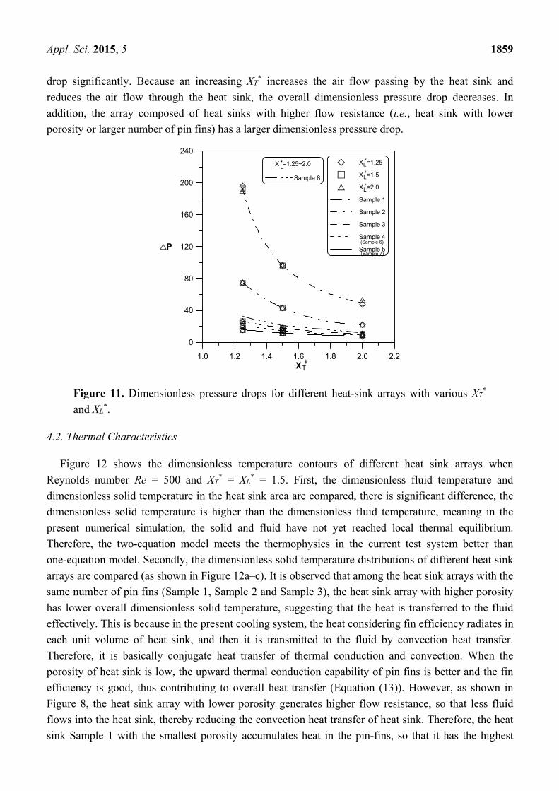
Appl. Sci. 2015, 5 1859
drop significantly. Because an increasing XT* increases the air flow passing by the heat sink and
reduces the air flow through the heat sink, the overall dimensionless pressure drop decreases. In
addition, the array composed of heat sinks with higher flow resistance (i.e., heat sink with lower
porosity or larger number of pin fins) has a larger dimensionless pressure drop.
Figure 11. Dimensionless pressure drops for different heat-sink arrays with various XT*
and XL*.
4.2. Thermal Characteristics
Figure 12 shows the dimensionless temperature contours of different heat sink arrays when
Reynolds number Re = 500 and XT* = XL
* = 1.5. First, the dimensionless fluid temperature and
dimensionless solid temperature in the heat sink area are compared, there is significant difference, the
dimensionless solid temperature is higher than the dimensionless fluid temperature, meaning in the
present numerical simulation, the solid and fluid have not yet reached local thermal equilibrium.
Therefore, the two-equation model meets the thermophysics in the current test system better than
one-equation model. Secondly, the dimensionless solid temperature distributions of different heat sink
arrays are compared (as shown in Figure 12a–c). It is observed that among the heat sink arrays with the
same number of pin fins (Sample 1, Sample 2 and Sample 3), the heat sink array with higher porosity
has lower overall dimensionless solid temperature, suggesting that the heat is transferred to the fluid
effectively. This is because in the present cooling system, the heat considering fin efficiency radiates in
each unit volume of heat sink, and then it is transmitted to the fluid by convection heat transfer.
Therefore, it is basically conjugate heat transfer of thermal conduction and convection. When the
porosity of heat sink is low, the upward thermal conduction capability of pin fins is better and the fin
efficiency is good, thus contributing to overall heat transfer (Equation (13)). However, as shown in
Figure 8, the heat sink array with lower porosity generates higher flow resistance, so that less fluid
flows into the heat sink, thereby reducing the convection heat transfer of heat sink. Therefore, the heat
sink Sample 1 with the smallest porosity accumulates heat in the pin-fins, so that it has the highest
1.0 1.2 1.4 1.6 1.8 2.0 2.2X
0
40
80
120
160
200
240
P
T
X =1.25
X =1.5
X =2.0
Sample 1
Sample 2
Sample 3
Sample 4
Sample 5
L
L
L
(Sample 6)
(Sample 7)
X =1.25~2.0
Sample 8
L*

Appl. Sci. 2015, 5 1860
overall dimensionless solid temperature. The heat sink Sample 3 with the largest porosity has more
cold inflow, and the dimensionless solid temperature is lower. In addition, the heat sink arrays with the
same porosity (Sample 3, Sample 4 and Sample 5) are compared, as shown in Figure 12c–e. The
overall dimensionless solid temperature of the Sample 3 heat sink array with more pin fins is lower
than that of the Sample 4 and Sample 5 heat sink arrays with fewer pin fins, especially in the first row
and the second row of heat sink array. In other words, Sample 3 with more pin fins has more heat
carried away, so it is unlikely to accumulate heat. However, according to the conjugate heat transfer
principle stated in Figure 12a–c, as Sample 3, Sample 4 and Sample 5 have the same porosity, they
have the same upward thermal conduction capability of pin fins. However, according to Figure 10, the
Sample 5 heat sink array with fewer pin fins has lower flow resistance, and it is supposed to have
higher air inflow. The reason that the dimensionless solid temperature of heat sink is slightly higher
than that of Sample 3 is explained below. First, the heat exchange area in unit volume of Sample 3
with more pin fins is far larger than that of Sample 4 and Sample 5 (see Table 1). This makes up the air
inflow during convection heat transfer. Secondly, as shown in Equations (7) and (8), Kim et al. [24]
indicated that the heat sink with smaller pin-fin diameter has larger convection heat transfer
coefficient. Therefore, the dimensionless solid temperature of Sample 3 heat sink array with smaller
pin-fin diameter is slightly lower than that of Sample 5.
Figure 12. Dimensionless temperature contours for various test samples with XT* = XL
* = 1.5
(the scales of X-axis and Y-axis are different): (a) Sample 1; (b) Sample 2; (c) Sample 3;
(d) Sample 4; and (e) Sample 5.
Figure 13 shows the influence of XT* and XL
* on the dimensionless temperature contours taking
Sample 1 heat sink array as an example when Reynolds number Re = 500. At fixed XL* = 2 and

Appl. Sci. 2015, 5 1861
variable XT* = 1.25, 1.5 and 2, the dimensionless solid temperature of heat sink increases with XT
*. As
the increase of XT* amplifies the bypass effect of air flow, the air flow entering the heat sink decreases,
and the heat removed decreases, so the solid part of heat sink accumulates heat and has higher
temperature. Relatively, when the XT* is larger, as the air flowing into the heat sink is lower, the fluid
has larger temperature rise though the pin fins transfer less heat to the fluid. This result is reflected in
the dimensionless fluid temperature contours. At fixed XT* = 2 and variable XL
* = 1.25, 1.5 and 2,
the dimensionless solid temperature and dimensionless fluid temperature in the same position
of various heat sinks have not varied with XL*, meaning XL
* is not a sensitive parameter to the overall
temperature distribution.
Figure 13. Dimensionless temperature contours for test Sample 1 with various values of
XT* and XL
* (the scales of X-axis and Y-axis are different): (a) XT* = 1.25; XL
* = 2;
(b) XT* = 1.5; XL
* = 2; (c) XT* = 2; XL
* = 2; (d) XT* = 2; XL
* = 1.5; and (e) XT* = 2;
XL* = 1.25.
Figure 14 shows the Nusselt numbers of various rows of heat sink array at different XT* and XL
*
values of Samples 1–5 when Reynolds number Re = 500. The number of pin fins of Sample 3 heat sink
is 9 × 9, the porosity is 0.75. This heat sink array has a higher Nusselt number among all the heat sink
arrays, and the Nusselt number of various heat sink arrays increases with decreasing XT*, but not varies
with XL*. This result conforms to the dimensionless temperature contours in Figures 12 and 13.

Appl. Sci. 2015, 5 1862
Figure 14. Nusselt number distributions along the main stream direction for various
heat-sink arrays: (a) Sample 1; (b) Sample 2; (c) Sample 3; (d) Sample 4; and
(e) Sample 5.

Appl. Sci. 2015, 5 1863
Figure 15 shows the relationship of average Nusselt number to the porosity and number of pin fins
of heat sink array when Reynolds number Re = 500. In order to clarify the influences of porosity and
number of pin fins on the average Nusselt number, the heat transfer characteristics of heat sink arrays
with higher porosity (Sample 6 and Sample 7, see Table 1) and heat sink array with more pin fins
(Sample 8, see Table 1) were also simulated. Figure 15a indicates that when the porosity of heat sink
with 9 × 9 pin-fins increases from 0.358 to 0.556, the average Nusselt number changes slightly. When
the porosity increases from 0.556 to 0.750, the average Nusselt number is increased significantly by
11.7% (for cases with XT* = 1.25)–24.8% (for cases with XT
* = 2). However, when the porosity
increases continuously from 0.750, the average Nusselt number decreases obviously. This is because
the overall heat exchange area decreases with the pin diameter of pin-fin heat sink, which is adverse to
convection heat transfer, and the upward thermal conduction capability of pin-fins declines, thus
reducing the fin efficiency. As a result, the average Nusselt number decreases on the contrary.
Figure 11b indicates that when the porosity is fixed at 0.75, increasing the number of pin fins
continuously can increase the average Nusselt number. In order to keep the fixed porosity, the pin
diameter must be reduced while the number of pin fins is increased; at this point, the overall heat
transfer area still increases with the number of pin fins, which is advantageous to the convection heat
transfer. According to empirical Equations (7) and (8) suggested by Kim et al. [24], the decrease in pin
diameter increases the convection heat transfer coefficient. Therefore, the average Nusselt number
increases with the number of pin fins. However, at the Reynolds number Re = 500, when the number
of pin fins is large, the average Nusselt number increases with the number of pin fins slowly. The
pressure drop of the heat sink array increases with the number of pin fins, thus preventing the air flow
from entering the heat sink effectively for cooling.
Figure 15. Average Nusselt numbers of pin-fin heat-sink array: (a) effect of heat-sink
porosity and (b) effect of pin-fin numbers.

Appl. Sci. 2015, 5 1864
4.3. Semi-Empirical Correlation
Figure 16 illustrates the energy-balance schematic diagram for the air flow heated via the heat sink
in this issue. The inlet air flow has the uniform temperature (Ti) and velocity (ui). According to
Figure 10, the average velocity of air flow into windward side (uw,k, i.e., the average velocity of
flow-in air flow) of each heat sink decreases along the downward stream. In other words, a part of
flow-in air continuously results in leakage air at each downward heat sink to join the bypass flow.
Therefore, the energy balance for the flow-in air heated via each heat sink can be expressed as follows:
( ) *,,,
1,,
2 kwkikopkwkw
i QTTCLHUU
u =−⋅⋅⋅⋅
+⋅⋅ +ρ
(15)
2,,
,kiko
kbTT
T+
= , i
kwkw u
uU ,
, = (16)
where Ti,k and To,k are the average air temperatures at the inlet and outlet faces of the kth heat sink,
respectively; Tb,k is the bulk mean temperature of the air through the kth heat sink; and Qw,k* is the heat
transferred to the air flow through the kth heat sink. Because that the leakage-flow effect, the mean
velocity of air flow through the kth heat sink is expressed as ui(Uw,k + Uw,k+1)/2. Besides, the Qw,k* is
less than the total heat (Qw,k) dissipated from the kth heat sink since that the heat carried by the leakage
air does not join to result in the To,k.
Figure 16. Energy-balance schematic diagram for the air flow heated via the heat sink.
Equations (17) and (18) are the definitions of the average Nusselt number (Nui,k and Nub,k) of the kth
heat sink separately based on Ti,1 (i.e., Ti) and Tb,k. Substitute Equations (17) and (18) into
Equation (15), the relationship between Nui,k and Nub,k can be written as Equation (19).
21,,
,,
)( LkTT
HQNu
fikw
kwki
⋅⋅−
⋅=
(17)
2,,
,,
)( LkTT
HQNu
fkbkw
kwkb
⋅⋅−
⋅= (18)
x
y ui
Ti uw,1 uw,2 uw,3 uw,4 uw,5 uw,6 uw,7
Qw,k ; Tw,k ; Tb,k ;hfs ; afs
uw,k+1uw,k
To,kTi,k
k=1, 2, …, 7

Appl. Sci. 2015, 5 1865
HUUL
Q
QNuNu
kwkw
k
kw
kwkbki
⋅⋅−
⋅+=+
−− Pr)
2Re(2 1,,1 ,
*,1
,1
,
(19)
Finally, a semi-empirical correlation (see Equation (20)) can be completed to be a closed form by
combined with Equations (7) and (8) suggested by Kim et al. [24], the present numerical data of Uw,k
plotted in Figure 10, and the assumption of Qw,k*/Qw,k = Uw,k+1/Uw,k. For the present numerical
simulation, C1 and C2 are 0.363 and 0.542, respectively (see Equation (7)).
( )
2
, 2
2
, , 11ε Re
2
fs fsb k
f
C
w k w k Tfs
T
h d a L HHNu
k d L
U U Sd HC a H
H S d d+
⋅ ⋅ ⋅ = ⋅ ⋅ + = ⋅ ⋅ ⋅ ⋅ ⋅ ⋅ ⋅ −
(20)
kw
kw
kw
kw
U
U
Q
Q
,
1,
,
*, +=
(21)
The comparison results of the present numerical Nusselt number with the semi-empirical
predictions and the experimental data for Sample 3 and Sample 5 heat-sink arrays with Re = 500 are
plotted in Figure 17. The predicted Nu values generally agree with those numerical data. In addition,
the numerical data and the predictions of Equation (20) also agree with the typical experimental
results, demonstrating the correctness of the present study.
Figure 17. Comparison results of Nusselt number with semi-empirical predictions and
experimental data: (a) Sample 3 and (b) Sample 5.
5. Conclusions
This work successfully proposed a porous model to numerically investigate the fluid flow and heat
transfer behaviors of the pin-fin heat-sink array situated in a rectangular channel in an in-line
arrangement with various relative center-to-center longitudinal and transverse distances between heat

Appl. Sci. 2015, 5 1866
sinks. The present porous approach used the Brinkman-Forchheimer model for fluid flow and
two-equation model for heat transfer. The pin-fin heat sinks with various porosities and pin-fin
numbers were employed. Some major conclusions are summarized as follows:
(1) By comparing with downstream heat sink, more air inflow leaks from the upstream heat sink.
The heat sink with lower porosity or larger number of pin fins has less air inflow and more leakage
flow. The air flow entering the heat sink is low and the leakage flow is high as the relative transverse
distance (XT*) between heat sinks is large. However, the effect of the relative longitudinal distance
(XL*) between heat sinks on the air flow entering the heat sink and the leakage flow is insignificant.
Changing XL* did not affect the dimensionless pressure drop, but decreasing XT
* would increase
dimensionless pressure drop significantly. In addition, the array composed of heat sinks with lower
porosity or larger number of pin fins has a larger dimensionless pressure drop.
(2) The dimensionless solid temperature is higher than the dimensionless fluid temperature,
meaning the solid and fluid have not yet reached local thermal equilibrium in the present numerical
simulation. Therefore, the two-equation model used for this issue is necessary. The Nusselt number of
various heat-sink arrays increases with decreasing XT*, but does not vary with XL
*. When the porosity
of the typical heat sink increases from 0.358 to 0.556, the average Nusselt number changes slightly.
However, the average Nusselt number is increased significantly by 11.7%–24.8% when the porosity
increases from 0.556 to 0.750, and then drops obviously when the porosity exceeds 0.750. Besides,
increasing the number of pin fins continuously can increase the average Nusselt number. However,
when the number of pin fins is large, the average Nusselt number increases with the number of pin
fins slowly.
(3) The present numerical simulations agree with the smoke flow visualization and heat transfer
measurement of the typical experiment, proving the correctness of the present study. Finally,
a semi-empirical correlation of Nusselt number for each heat sink in the present heat-sink array
is proposed.
Acknowledgments
The authors would like to thank the Ministry of Science and Technology of the Republic of China
for financially supporting this research under Contract Nos. MOST 103-2632-E-270-001-MY3,
MOST 104-2221-E-270-002, MOST 104-2622-E-270-005-CC3 and MOST 104-2221-E-270-005.
Author Contributions
Tzer-Ming Jeng led this work and conducted the numerical simulation, experimental measurement
and theoretical analysis; and Sheng-Chung Tzeng participated discussions and was responsible
for correspondence.
Conflicts of Interest
The authors declare no conflict of interest.

Appl. Sci. 2015, 5 1867
References
1. Tahat, M.; Kodah, Z.H.; Jarrah, B.A.; Probert, S.D. Heat transfers from pin-fin arrays
experiencing forced convection. Appl. Energy 2000, 67, 419–442.
2. Chang, S.W.; Yang, T.L.; Huang, C.C.; Chiang, K.F. Endwall heat transfer and pressure drop in
rectangular channels with attached and detached circular pin-fin array. Int. J. Heat Mass Transfer
2008, 51, 5247–5259.
3. Zhuan, R.; Wang, W. Boiling heat transfer characteristics in a microchannel array heat sink with
low mass flow rate. Appl. Therm. Eng. 2013, 51, 65–74.
4. Jeng, T.M.; Tzeng, S.C.; Liu, C.H.; Lin, D.J.; Yang, B.J. Design and Manufacture of an
Energy-saving LED Lantern with Paper-cut Figure Projection Function. Smart Sci. 2014, 2,
13–19.
5. Ritchey, S.N.; Weibel, J.A.; Garimella, S.V. Local measurement of flow boiling heat transfer in
an array of non-uniformly heated microchannels. Int. J. Heat Mass Transfer 2014, 71, 206–216.
6. Taji, S.G.; Parishwad, G.V.; Sane, N.K. Enhanced performance of horizontal rectangular fin array
heat sink using assisting mode of mixed convection. Int. J. Heat Mass Transfer 2014, 72,
250–259.
7. El-Sayed, S.A.; Mohamed, S.M.; Abdel-latif, A.M.; Abouda, A.E. Investigation of turbulent heat
transfer and fluid flow in longitudinal rectangular-fin arrays of different geometries and shrouded
fin array. Exp. Therm. Fluid Sci. 2002, 26, 879–900.
8. Moores, K.A.; Kim, J.; Joshi, Y.K. Heat transfer and fluid flow in shrouded pin fin arrays with
and without tip clearance. Int. J. Heat Mass Transfer 2009, 52, 5978–5989.
9. Dogan, M.; Sivrioglu, M. Experimental and numerical investigation of clearance gap effects on
laminar mixed convection heat transfer from fin array in a horizontal channel—A conjugate
analysis. Appl. Therm. Eng. 2012, 40, 102–113.
10. Zhang, Y.; Liu, J.; Chong, D.; Yan, J. Experimental investigation on the heat transfer and flow
performances of the fin array with shield in bypass. Int. J. Heat Mass Transfer 2013, 56, 674–682.
11. Roth, R.; Lenk, G.; Cobry, K.; Woias, P. Heat transfer in freestanding microchannels with in-line
and staggered pin fin structures with clearance. Int. J. Heat Mass Transfer 2013, 67, 1–15.
12. Mei, D.; Lou, X.; Qian, M.; Yao, Z.; Liang, L.; Chen, Z. Effect of tip clearance on the heat
transfer and pressure drop performance in the micro-reactor with micro-pin-fin arrays at low
Reynolds number. Int. J. Heat Mass Transfer 2014, 70, 709–718.
13. Morega, A.M.; Bejan, A.; Lee, S.W. Free stream cooling of a stack of parallel plates. Int. J. Heat
Mass Transfer 1995, 38, 519–531.
14. Narasimhan, S.; Majdalani, J. Compact heat sink simulations in both forced and natural
convection flows. In Proceedings of the 8th AIAA/ASME Joint Thermophysics and Heat Transfer
Conference, St. Louis, MI, USA, 24–26 June 2002; pp. 24–26.
15. Kim, S.J.; Kim, D. Forced convection in microstructures for electronic equipment cooling.
J. Heat Transfer 1999, 121, 639–645.
16. Kim, D.; Kim, S.J. Compact modeling of fluid flow and heat transfer in straight fin heat sinks.
J. Electron. Packag. 2004, 126, 247–255.

Appl. Sci. 2015, 5 1868
17. Yu, E.; Joshi, Y. Heat transfer enhancement from enclosed discrete components using pin-fin heat
sinks. Int. J. Heat Mass Transfer 2002, 45, 4957–4966.
18. Jeng, T.M. A porous model for the square pin-fin heat sink situated in a rectangular channel with
laminar side-bypass flow. Int. J. Heat Mass Transfer 2008, 51, 2214–2226.
19. Narasimhan, A.; Reddy, B.V.K. Laminar forced convection in a heat generating bi-disperse porous
medium channel. Int. J. Heat Mass Transfer 2011, 54, 636–644.
20. Narasimhan, A.; Reddy, B.V.K.; Dutta, P. Thermal management using the bi-disperse porous
medium approach. Int. J. Heat Mass Transfer 2012, 55, 538–546.
21. Feng, S.S.; Kim, T.; Lu, T.J. Numerical investigation of forced convection in pin/plate-fin heat
sinks heated by impinging jet using porous medium approach. Int. J. Numer. Methods Heat
Fluid Flow 2013, 23, 88–107.
22. Holman, J.P. Heat Transfer; Mcgraw-Hill: New York, NY, USA, 1990; pp. 32–33.
23. Jeng, T.M.; Tzeng, S.C. A semi-empirical model for estimating permeability and inertial
coefficient of pin-fin heat sinks. Int. J. Heat Mass Transfer 2005, 48, 3140–3150.
24. Kim, D.; Kim, S.J.; Ortega, A. Compact modeling of fluid flow and heat transfer in pin fin heat
sinks. J. Electron. Packag. 2004, 126, 342–350.
25. Roache, P.J. Computational Fluid Dynamics; Hermosa: Albuquerque, NM, USA, 1972;
pp. 139–173.
26. Patankar, S.V. Numerical Heat Transfer and Fluid Flow; McGraw Hill-Hemisphere: New York,
NY, USA, 1980; pp. 113–137.
27. Lee, S.L. A strong implicit solver for two-dimensional elliptic differential equations. Numer. Heat
Transfer Part B 1989, 16, 161–178.
28. Jeng, T.M.; Tzeng, S.C.; Tang, F.Z. Fluid flow and heat transfer characteristics of the porous
metallic heat sink with a conductive cylinder partially filled in a rectangular channel. Int. J. Heat
Mass Transfer 2010, 53, 4216–4227.
29. Moffat, R.J. Contributions to the theory of single-sample uncertainty analysis. J. Fluids Eng. 1982,
104, 250–258.
© 2015 by the authors; licensee MDPI, Basel, Switzerland. This article is an open access article
distributed under the terms and conditions of the Creative Commons Attribution license
(http://creativecommons.org/licenses/by/4.0/).