Numerical Modeling of the Interaction of Normal Fault and ...
47
Numerical Modeling of the Interaction of Normal Fault and Shallow Embedded Foundation Mehdi Ashtiani ( [email protected] ) Babol Noshirvani University of Technology Mohammadreza Jahanshahi Nowkandeh Babol Noshirvani University of Technology Amirmohammad Kayhani Babol Noshirvani University of Technology Research Article Keywords: Normal fault rupture, Shallow foundation, Embedment depth, Numerical modeling Posted Date: May 27th, 2021 DOI: https://doi.org/10.21203/rs.3.rs-514125/v1 License: This work is licensed under a Creative Commons Attribution 4.0 International License. Read Full License Version of Record: A version of this preprint was published at Bulletin of Earthquake Engineering on July 6th, 2021. See the published version at https://doi.org/10.1007/s10518-021-01172-3.
Transcript of Numerical Modeling of the Interaction of Normal Fault and ...
Numerical Modeling of the Interaction of NormalFault and Shallow Embedded FoundationMehdi Ashtiani ( [email protected] )
Babol Noshirvani University of TechnologyMohammadreza Jahanshahi Nowkandeh
Babol Noshirvani University of TechnologyAmirmohammad Kayhani
Babol Noshirvani University of Technology
Research Article
Keywords: Normal fault rupture, Shallow foundation, Embedment depth, Numerical modeling
Posted Date: May 27th, 2021
DOI: https://doi.org/10.21203/rs.3.rs-514125/v1
License: This work is licensed under a Creative Commons Attribution 4.0 International License. Read Full License
Version of Record: A version of this preprint was published at Bulletin of Earthquake Engineering on July6th, 2021. See the published version at https://doi.org/10.1007/s10518-021-01172-3.

Numerical modeling of the interaction of normal fault and shallow embedded
foundation
Mehdi Ashtiani1,*, Mohammadreza Jahanshahi Nowkandeh1, Amirmohammad Kayhani1
1Faculty of Civil Engineering, Babol Noshirvani University of Technology, Babol, Iran
*Corresponding author: [email protected]
Abstract
The consequences to structures caused by permanent fault displacement has been investigated for dip-slip faulting,
but not for the effect of the embedment depth on the interaction between a normal fault rupture and shallow
embedded foundation. This study investigated the effect of the embedment depth on the interaction of normal
fault rupture and shallow foundation using a numerical model validated with centrifuge experiments. It was found
that a gapping interaction mechanism and foundation distress occurred at different foundation positions relative
to the fault rupture outcrop for an embedded foundation in comparison with a surface foundation. The extent of
this area depended on the combined influences of the foundation position, foundation surcharge, embedment
depth, and fault dip angle. The sidewalls of the shallow embedded foundation were observed to act as kinematic
constraints and had considerable influence on the rotation and displacement of the foundations. With regard to the
level of rotation and displacement of the embedded foundation, the lateral earth pressure distribution on the
footwall sidewall was similar to that of Rankine active earth pressure in a triangular distribution and on the
hangingwall sidewall as a parabolic distribution of passive earth pressure. Foundations laid on loose soil exhibited
less rotation than those on dense soil because the fault ruptures were absorbed or bifurcated around both sides of
the foundation.
Keywords: Normal fault rupture, Shallow foundation, Embedment depth, Numerical modeling
1 Introduction
The propagation of a fault rupture through the soil layer is a hazard associated with fault-induced dislocation.
Most research on this occurrence initiated after the 1999 earthquakes in Turkey and Taiwan (Ulusay et al. 2002;
Dong et al. 2003) and the 2008 earthquake in Wenchuan, China (Lin and Ren 2009). The destruction from these
earthquakes clarified the effect of a fault rupture on structures located near the fault trace at the ground surface.
These studies focused on free-field fault rupture propagation, the interaction of the structures and the fault, and
mitigation strategies for decreasing the effects of fault-structure interaction by field investigations (Faccioli et al.
2008; Lin et al. 2006), experimental studies (Bransby et al. 2008a,b; Rojhani et al. 2012; Ashtiani et al. 2015;
Ahmadi et al. 2018; Yao and Takemura 2019; Sadra et al. 2020; Fadaee et al. 2020; Yao et al. 2020a, 2020b), and
numerical modeling (Bray et al. 1994; Anastasopoulos et al. 2007, 2008, 2009; Oettle and Bray 2016; Baziar et
al. 2019; Agalianos et al. 2020; Naiej and Soroush 2020; Azizkandi et al. 2021).
Research on free-field fault rupture propagation was performed to determine the pattern of rupture
propagation through the overburden (Cole and Lade 1984; Bray et al. 1994a; Ng et al. 2012; Yao et al. 2020a)
and the height of fault rupture emergence at the ground surface (Bray et al. 1994b). The studies showed that the
pattern of rupture propagation of a dip-slip fault through the soil layer depended on the alluvium depth, soil
characteristics, fault dip angle, and fault type. A fault rupture can interact with either subsurface or surface
structures. Because of the high probability of a fault rupture striking a subsurface structure, such structures could
sustain major damage (Baziar et al. 2014; Sabagh and Ghalandarzadeh 2020a, b). Thus, it is necessary to
investigate strategies for decreasing the hazards associated with faulting on these types of structure (Ni et al. 2018;
Rasouli and Fatahi 2020). Many buildings have been destroyed by permanent ground displacement during an
earthquake. However, the fault ruptures can be diverted in some cases or the level of damage to a building could

be reduced (Faccioli et al. 2008). This has been observed in studies on fault rupture-structure interaction that have
specified the influence of important parameters on the interaction (e.g. Bransby et al. 2008a, 2008b; Gazetas et al.
2008; Anastasopoulos et al. 2009; Ashtiani et al. 2015; Oettle and Bray 2016; Naiej and Soroush 2020). These
parameters include the type of fault, fault dip angle, type and stiffness of the soil, alluvium depth on bedrock,
building weight, type and rigidity of the foundation, position of the foundation relative to fault rupture emergence
at the ground surface, and the condition of the superstructure. It can be seen that provisions for the design
framework of buildings in faulting zones have not been addressed because faults are of unknown nature and their
behavior is unpredictable and because of ambiguities in the fault rupture-structure interaction. Further
investigation is required on the different aspects of structure-fault interaction and strategies for decreasing the
hazards associated with the fault rupture on buildings.
Most of the research mentioned above has been performed on buildings with shallow foundations located
at the ground surface (i.e. without embedment depth). In urban settings, a lack of space and the need for parking
space require excavation of foundations for the construction of buildings with one or more basement stories. It is
clear that ignoring to address the embedment depth of shallow foundations can affect these previously studied
behaviors. Therefore, the influence of foundation embedment depth on the building-fault rupture interaction must
be investigated. Ashtiani et al. (2015) investigated the effect of foundation embedment depth on the interaction of
buildings and reverse fault rupture using centrifuge modeling. Ashtiani and Ghalandarzadeh (2020) and Naeij et
al. (2019) carried out complementary studies on the interaction of embedded shallow foundations and reverse
faulting. They concluded that the combined effect of the foundation embedment depth, surcharge, and position
will cause a change in the interaction behavior. Loli et al. (2011, 2012) investigated the behavior of caisson
foundations affected by dip-slip faults. Their results showed that the caisson foundation caused the deviation or
diffusion of the fault rupture. Also, with regard to the foundation rigidity and its constraints, fault-induced
dislocation had relatively little influence on the caisson foundation.
As the interaction of a shallow embedded foundation and a normal fault rupture has not yet been
investigated, the current study focused on the effect of foundation embedment depth. Finite element software and
a modified Mohr-Coulomb constitutive model were used when considering the internal friction angle and dilation
softening behavior and were implemented as a user subroutine into the program. The numerical model was
validated according to the centrifuge results. The effect of the parameters of foundation embedment depth, fault
dip angle, position of the foundation relative to the fault rupture, and the foundation surcharge were considered in
the model. In this study, the foundation rotation, profile of the ground surface, and the earth pressure distribution
on the foundation sidewalls have been examined.
2 Problem definition
Fig. 1a shows the interaction of a shallow embedded foundation and normal faulting for the problem under study.
This includes a uniform soil layer with thickness H = 25 m and model length L, where the normal fault moves
with dip angle α and creates downward displacement having vertical component h. After propagation of the fault
rupture through the soil layer, the shear-band strikes a shallow foundation with breadth B, embedment depth D,
and applied pressure q. The distance between the bottom left edge of the foundation and the fault rupture
emergence at the ground surface specifies the position of the foundation. As a result of fault rupture propagation,

the ground surface is displaced (δy) and the foundation experiences rotation θ and translational displacement Δ.
Embedment depths of 0, 3, 6, and 9 m were examined. A depth of zero relates to the foundation at the ground
surface (i.e. surface foundation) and the other depths are for shallow embedded foundations.
It is important to note that, when a foundation is embedded, the position at which the free-field fault
rupture strikes the foundation base will change. In other words, for a specified foundation position, the values of
parameter s will not be the same at different embedment depths, as is shown in Fig. 1b. Because parameter s is a
factor effecting the foundation-fault interaction, the horizontal position of the foundation will change with an
increase in the embedment depth in order to maintain a constant value for s.
Fig. 1 Problem definition: (a) interaction between a normal fault rupture and shallow foundation with breadth B,
embedment depth D, and surcharge q; (b) positions of shallow foundations relative to free-field fault rupture
2.1 Finite element model
Two-dimensional plane strain numerical modeling was performed using ABAQUS finite element software. To
minimize the influence of the boundaries on the results of modeling, the width of the models was set at L= 4H
(Bray et al. 1994a). A 4-node rectangular plane strain element with a width of dFE = 0.5 m was used to model the
soil. The mesh size was selected using sensitivity analysis for models with elements of 1.0 and 0.5 m in width. It
was found that models with element widths of 0.5 m were more consistent with the experimental results. The
α
Moving block
D= 0, 3, 6, 9m
S
h
H=25m
B
q
L
y
x
δy
Foundation
θ
Δ
Stationary block
Bedrock
(a)
(b)
Free-field
fault rupture
Surface foundation
Embedded foundation S
S
Free-field
fault rupture
D

position of the fault outcropping and the foundation rotation were predicted with better accuracy in models with
an element width of 0.5 m than of 1.0 m.
A foundation with breadth B and embedment depth D was modeled with beam elements and high elastic
parameters to provide a rigid foundation. A beam element was used to model the surface foundation. For the
embedded foundation, four beam elements were used to model the elements of the bottom, top, and sidewalls of
the foundation such that the connection of these elements created a box with embedment depth D. The numerical
analysis assumed that the bending rigidity of the foundation sidewalls was similar to that of the foundation
basement.
The interface between the sidewalls and base of the embedded foundation and the soil was considered
using a gap element (Anastasopoulos et al. 2008). Gap elements are infinite in compression, but offer no resistance
in tension and their behavior for shearing follows Columbus's friction law. The coefficient of friction was based
on the friction between the soil and the concrete to be 2/3φ, where φ is the internal friction angle of the soil.
Displacement was applied to the right boundaries of the model (the hanging wall) in a pseudo-static manner in
small increments to prevent the numerical model from becoming unstable during the solution.
2.2 Soil constitutive model
Studies have shown that the post-peak behavior of the soil is important to the accurate prediction of fault rupture
propagation through the soil layer and the fault rupture-structure interaction (Anastasopoulos et al., 2007 and
2009; Oettle and Bray, 2016; Naiej and Soroush 2020). Dense sand exhibits post-peak softening and reaches a
critical state (residual) condition. In the present study, the modified Mohr-Coulomb constitutive model with post-
peak softening was incorporated into ABAQUS through a user subroutine (UMAT), which was similar to that of
Anastasopoulos et al. (2007). In this constitutive model, the post-peak behavior, as the peak friction angle and
dilation angle (φP and ψP) linearly decreased to the residual values (φres and ψres = 0) with an increase in the
plastic shear strain (γP ). φmob = {φP − φP−φresγfP γPφres for 0 ≤ γP < γfPfor γP ≥ γfP } (1)
ψmob = {ψP (1 − γPγfP )ψres = 0 for 0 ≤ γP < γfPfor γP ≥ γfP } (2)
where γfP is the plastic shear strain at failure in which softening is complete.
Anastasopoulos et al. (2007) proposed Eq. (3) to calculate 𝛾𝑓𝑝 by considering the mesh dependency
(Gudehus and Nubel, 2004) and scale effects (Muir Wood, 2002) when comparing the results of numerical
modeling with those of the centrifuge experiment. 𝛾𝑓𝑝 = 𝛿𝑥𝑝−𝛿𝑥𝑦𝐷 + 𝛿𝑥𝑓−𝛿𝑥𝑝𝑑𝐹𝐸 𝑁 (3)
where N is the centrifugal acceleration, dFE is the mesh size in the shear-band area of numerical modeling, D is
the sample height in the direct shear test, and 𝛿𝑥𝑦 , 𝛿𝑥𝑝 , and 𝛿𝑥𝑓 were obtained from the results of the direct
shear tests. When modeled as a real-scale problem, N must be equal to one.

In this study, dense and loose granular types of sand were used in the modeling. The strength and
deformation parameters of the ideal granular soil types are shown in Table 1. The soil modulus of elasticity was
considered as a variable that is a function of the soil depth.
Table 1 Soil parameters used in numerical analysis (Anastasopoulos et al. 2007)
Poisson
ratio, ν
Modulus of
elasticity, E
(MPa)
Failure
plastic shear
strain, 𝛾𝑓𝑝
Dilation
angle, ψP (°)
Residual
friction
angle, φres (°)
Peak friction
angle φP (°)
Density γ (kg m3⁄ )
Sand
0.3 2.25Z* 0.05 18 30 45 2000 dense
0.35 0.75Z 0.08 5 30 32 1600 loose
*Z is soil depth.
2.3 Parameters used in numerical modeling
The parameters used in the numerical analysis, the embedment depth of the foundation, its location relative to the
fault rupture trace at the ground surface, foundation surcharge, and fault dip angle are summarized in Table 2. The
numerical models were analyzed for a soil depth of 25 m and a foundation breadth of 10 m. Assuming the weight
per unit of area of each story to be 10 kN/m2, the foundation surcharges considered were equal to 40, 60, 80, 100,
and 120 kPa. These pressures represent 4, 6, 8, 10, and 12 story buildings, respectively. The embedment depth to
breadth ratios were D/B = 0 (surface foundation) and D/B = 0.3, 0.6, and 0.9 (embedded foundations). The rigidity
of the foundation of EI = 108 kN.m2 represents a rigid foundation. The dip angles of the normal fault used for
numerical analysis were α = 45°, 60°, 75° and 90°.
The maximum ratio of fault vertical displacement to soil depth was h/H = 5%, where h = 1.25 m and H
= 25 m. This value of displacement for a normal fault is approximately proportional to an earthquake of magnitude
6.8 as presented in the correlation by Wells and Coppersmith (1994).
Table 2 Parameters used in parametric analysis
Ranges Unit Parameters
dense, loose - soil
0, 0.3, 0.6, 0.9 - foundation depth ratio (D/B)
-0.5, 0, 0.25, 0.5, 0.75, 1.0 - foundation position ratio (s/B)
40, 60, 80, 100, 120 kPa foundation surcharge (q)
45, 60, 75, 90 ° dip angle of normal fault (α)
3 Validation
Normal fault rupture-shallow foundation interaction tests were conducted in a beam centrifuge at the University
of Dundee (Bransby et al. 2008a). These tests were conducted at 115g on Dr = 60% Fontainebleau sand and

simulated the free-field normal fault rupture propagation and normal fault rupture-foundation interaction. They
investigated the patterns of fault rupture propagation through a sandy soil deposit and the different mechanisms
for the different foundation positions. The foundation was located on a 25 m sand deposit. The parameters for the
centrifuge model tests for verification with numerical analysis are summarized in Table 3 (Bransby et al. 2008a).
The properties of the sand used in the centrifuge model tests are presented in Table 4 (Anastasopoulos et al. 2007).
Table 3 Characteristics of models used to validate numerical analysis (Bransby et al. 2008a)
Test
No. Height, H
(m)
Length,
L (m)
Dip angle of
fault, α (°) Foundation
breadth, B (m)
Foundation
position, s/B
Foundation
surcharge, q (kPa)
1 25 76 60 - - -
2 25 76 60 10 0.31 37
3 25 76 60 10 0.29 90
Table 4 Soil parameters used to validate numerical analysis (Anastasopoulos et al. 2007)
Failure plastic
shear strain, 𝛾𝑓𝑝
Dilation angle,
ψP (°)
Residual
friction angle, φres (°)
Peak friction
angle,
φP (°)
Poisson
ratio,
ν
Modulus of
elasticity, E
(MPa)
Density,
γ (kg m3⁄ )
0.244 6 30 36 0.35 45 1570
Before investigation of the fault rupture-foundation interaction, free-field fault rupture propagation
through the soil layer was modeled to provide a base condition. Fig. 2a shows the deformed model for the free-
field condition at H = 25 m in dry sand at Dr = 60% that has been subjected to a normal fault at α = 60°. In Figs.
2a and 2b, the fault rupture deviated towards the hanging wall as it propagated toward the ground surface. A
comparison shows satisfactory consistency between the results of the centrifuge model tests and numerical
analysis. Fig. 2c shows good agreement for vertical displacement δy at the soil surface between the experimental
and numerical results.
S2
S1
(a) (b)
Straight direction
of fault rupture
Straight direction
of fault rupture

(c)
Fig. 2 Free-field normal faulting propagation at a dip angle of 60° through 2.16 m of Fontainebleau sand at Dr =
60%: (a) deformed centrifuge model (Bransby et al. 2008a); (b) deformed numerical model; (c) vertical
displacement profile at soil surface
In Table 3, tests 2 and 3 verify the numerical modeling of normal fault rupture-foundation interaction.
All parameters were similar to those of the free-field test, except that the foundation surcharges were different (37
and 90 kPa represent light and heavy foundations, respectively) and were approximately positioned at s/B = 0.3.
Figs. 3 and 4 shows the satisfactory comparison of the centrifuge results are compared to the numerical predictions
in terms of the deformed model, the vertical displacement profile of ground surface, and the rotation of foundation.
The numerical model was able to simulate the diversion of fault rupture towards the footwall for a foundation
resting on a hanging wall as similar to the centrifuge experiment results. The vertical displacement profile at the
ground surface and the foundation rotation were similar. It appears that the numerical model can appropriately
simulate the fault rupture-foundation interaction.
-3.5
-3
-2.5
-2
-1.5
-1
-0.5
0
-20 -10 0 10 20
Ver
tica
l gro
un
d s
urf
ace
dis
pla
cem
ent,
δy (
m)
Horizontal distance, x (m)
Centrifuge modelings
FE Analyses
h=0.24m
h=0.58m
h=1.02m
h=1.48m
h=2.47m
h=1.92m
S2
S1
(a) (b)

(d) (c)
Fig. 3 Foundation-normal fault rupture interaction mechanism for B = 10 m, q = 37 kPa, S = 3.1 m, and h = 2.03
m: (a) deformed centrifuge model (Bransby et al. 2008a); (b) deformed numerical model; (c) vertical displacement
profile at ground surface; (d) rotation of foundation
(d) (c)
Fig. 4 Foundation-normal fault rupture interaction mechanism for B = 10 m, q = 90 kPa, S = 2.9 m, and h = 2.16
m: (a) deformed centrifuge model (Bransby et al. 2008a); (b) deformed numerical model; (c) vertical displacement
profile at ground surface; (d) rotation of foundation
4. Results and Discussion
The interaction between the normal fault rupture and shallow embedded foundation was investigated. Initially,
the free-field model determined the position where the fault rupture would have outcropped in the absence of a
0
1
2
3
4
5
6
0 0.5 1 1.5 2
Rta
tion
, θ
(°)
Fault throw, h (m)
Centrifuge modeling
FE Analysis
-2.5
-2
-1.5
-1
-0.5
0
-20 -15 -10 -5 0 5 10 15 20
Ver
tica
l gro
un
d s
urf
ace
dis
pla
cem
ent,
δy (
m)
horizontal distance, x (m)
Centrifuge modelings
FE Analyses
h= 0.27m
h= 0.62m
h= 1.10m
h= 1.55m
h= 2.03m
0
0.5
1
1.5
2
2.5
0 0.5 1 1.5 2
Rota
tion
, θ(
°)
Fault throw, h (m)
Centrifuge modeling
FE Analysis
-2.5
-2
-1.5
-1
-0.5
0
-20 -15 -10 -5 0 5 10 15 20
Ver
tica
l gro
un
d s
urf
ace
dis
pla
cem
ent,
δy (
m)
horizontal distance, x (m)
Centrifuge modeling
FE Analyses
h=0.36m
h=0.66m
h=0.99m
h=1.31m
h=1.76m
h=2.01m
S2
S1
(a) (b)
shallow embedded foundation. Then, the foundation was placed at various distances relative to the location of the
free-field fault rupture outcrop and at different depths. In the normal fault rupture-shallow embedded foundation
interaction, the location of the foundation, its embedment depth and surcharge, as well as the fault dip angle could
have affected the behavior of the foundation. Therefore, a parametric study was conducted to derive an
understanding of the normal fault rupture-shallow embedded foundation interaction. In the following sections, the
results of the parametric analysis are presented and discussed.
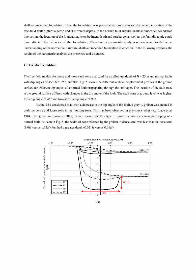
4.1 Free-field condition
The free field models for dense and loose sand were analyzed for an alluvium depth of H = 25 m and normal faults
with dip angles of 45°, 60°, 75°, and 90°. Fig. 5 shows the different vertical displacement profiles at the ground
surface for different dip angles of a normal fault propagating through the soil layer. The location of the fault trace
at the ground surface differed with changes in the dip angle of the fault. The fault zone at ground level was highest
for a dip angle of 45° and lowest for a dip angle of 90°.
It should be considered that, with a decrease in the dip angle of the fault, a gravity graben was created in
both the dense and loose soils in the faulting zone. This has been observed in previous studies (e.g. Lade et al.
1984, Hazeghian and Soroush 2016), which shows that this type of hazard occurs for low-angle dipping of a
normal fault. As seen in Fig. 5, the width of zone affected by the graben in dense sand was less than in loose sand
(1.0H versus 1.32H), but had a greater depth (0.021H versus 0.01H).
(a)
-8
-7
-6
-5
-4
-3
-2
-1
0
-1.25 -0.75 -0.25 0.25 0.75 1.25
Norm
aliz
ed g
rou
nd
su
rfac
e d
eform
atio
n,
δy/H
Normalized horizontal position, x /H
45°
60°
75°
90°
h/H=1.0%
h/H=5.0%
0.021H
1.0H

(b)
Fig. 5 Vertical displacement profile at ground surface for normal free-field fault rupture with dip angles of 45°,
60°, 75°, 90°: (a) dense sand; (b) loose sand
4.2 Effect of embedment depth and location of foundation
To investigate the effect of the embedment depth of a shallow foundation and its location on the normal fault
rupture-foundation interaction, foundations with a width of 10 m, embedment depths of D/B = 0, 0.3, 0.6, 0.9, and
surcharges q = 40 and 100 kPa were modeled at s/B = -0.5, 0, 0.25, 0.5, 0.75, and 1.0 for a normal fault at α = 60°.
Fig. 6 shows the foundation rotation relative to the foundation location in dense and loose sand. The results show
that the effect of the embedment depth on the fault-foundation interaction significantly depended on the location
of the foundation relative to the fault rupture and the foundation surcharge. This can be attributed to a change in
the mechanism of the fault rupture-foundation interaction.
The interaction mechanisms were hanging wall, gapping, and footwall types (discussed by Ahmed and
Bransby 2009), which vary with a change in the embedment depth and the location of the foundation. As seen,
for s/B < 0.5 at q = 40 and 100 kPa, an increase in the embedment depth increased the foundation rotation in dense
and loose sand. This increase in the embedment increased the likelihood of the fault rupture striking the bottom
of the embedded foundation relative to the surface foundation (D = 0). In most cases, the interaction mechanism
for embedded foundations was the gapping type.
For s/B ≥ 0.5 in q = 40 kPa and s/B ≥ 0.75 in q = 100 kPa, the rotation of the surface foundation was
greater than for the shallow embedded foundation, which could relate to the interaction mechanism of the
foundations. When the foundation moved towards the hanging wall, the interaction mechanism of the surface
foundation was gapping. The mechanism for the shallow embedded foundation gradually changed to a footwall,
the fault rupture was diverted to the right side of the embedded foundation, and the foundation rotation decreased.
-7
-6
-5
-4
-3
-2
-1
0
-1.25 -0.75 -0.25 0.25 0.75 1.25
Norm
aliz
ed g
rou
nd
su
rfac
e d
eform
atio
n,
δy/H
Normalized horizontal position, x /H
45°
60°
75°
90°
h/H=1.0%
h/H=5.0%
0.01H
1.32H

q =
4
0 k
Pa
q =
1
00
kP
a
(b) (a)
Fig. 6 Rotation of foundation in terms of position vs. embedment depth: (a) dense sand; (b) loose sand
The models deformed by the interaction of the fault rupture and foundation for surcharges of 40 and 100
kPa are shown in Figs. 7 and 8, respectively. Fig. 7a shows that the interaction mechanism for the surface
foundation located at s/B = 0 on dense sand was the hanging wall type. With an increase in the foundation
embedment depth to 3 and 6 m, the fault rupture struck the bottom of the foundation, resulting in the formation of
a gapping mechanism in addition to the hanging wall mechanism. When the embedded foundation was located in
the faulting zone, the sidewalls of the foundation acted as kinematic constraints and the foundation was forced to
follow fault-induced deformation. A change in the embedment depth changed the type of interaction mechanism
and played a more significant role in the degree of foundation rotation. Fig. 8a shows that the interaction
mechanism stayed the same with an increase in the embedment depth, but the embedded foundations experienced
greater rotation than the surface foundations. This could be attributed to the kinematic constraints caused by the
sidewalls of the embedded foundation.
Fig. 7b shows that a change in the location of the foundation to s/B = 0.5 at q = 40 kPa caused the fault
rupture to strike the middle of the base of the surface foundation and caused a high degree of foundation rotation.
For the embedded foundation, the fault rupture diverted to the right of the foundation base and, despite the gapping
mechanism, experienced less rotation. An increase in the surcharge load to 100 kPa caused the fault rupture to
divert to the left side of the surface foundation. For embedded foundations, the fault rupture was confined to
beneath the foundation and caused more damage, as shown in Fig. 8b.
The interaction mechanisms of the foundations laid on loose sand for surcharges of 40 and 100 kPa are
shown in Figs. 7c and 8c, respectively. At q = 40 kPa, the fault rupture directly struck the base of the surface
foundation; however, for shallow embedded foundations, the main fault rupture was diverted to the right side of
-2
0
2
4
6
8
10
-0.5 -0.25 0 0.25 0.5 0.75 1
Rota
tion,
Ѳ(°
)
Foundation position, s/B
D/B = 0
D/B = 0.3
D/B = 0.6
D/B = 0.9
-2
0
2
4
6
8
10
-0.5 -0.25 0 0.25 0.5 0.75 1
Rota
tion,
Ѳ(°
)
Foundation position, s/B
D/B = 0D/B = 0.3D/B = 0.6D/B = 0.9
-2
0
2
4
6
8
10
-0.5 -0.25 0 0.25 0.5 0.75 1
Rota
tion,
Ѳ(°
)
Foundation position, s/B
D/B = 0
D/B = 0.3
D/B = 0.6
D/B = 0.9
-2
0
2
4
6
8
10
-0.5 -0.25 0 0.25 0.5 0.75 1
Rota
tion,
Ѳ(°
)
Foundation position, s/B
D/B = 0
D/B = 0.3
D/B = 0.6
D/B = 0.9

the foundation. An increase in the surcharge to 100 kPa, caused the rupture to divert toward the footwall and the
surface foundation remained on the hanging wall. However, the rupture bifurcated in the shallow embedded
foundations. These mechanisms produced similar results in the case of dense sand.
Fig. 7 Model deformed by fault-foundation interaction vs. embedment depth at q = 40 kPa and α = 60°: (a) s/B =
0, dense sand; (b) s/B = 0.5, dense sand; (c) s/B = 0.5, loose sand
D/B=0
D/B=0.3
D/B=0.6
D/B=0.9
(a) (b) (c)
D/B=0
D/B=0.3
D/B=0.6
D/B=0.9
(a) (b) (c)

Fig. 8 Model deformed by fault-foundation interaction vs. embedment depth at q = 100 kPa and α = 60°: (a) s/B
= 0, dense sand; (b) s/B = 0.5, dense sand; (c) s/B = 0.5, loose sand
Figs. 6a and 6b show that surface foundations located on dense sand experienced greater rotation than
those located on loose sand. This can be attributed to the ability of the loose soil to absorb fault-induced
displacement and diffuse the rupture when it approached the foundation. This can also be seen by comparing the
mechanisms presented in Figs. 7b and 7c and Figs. 8b and 8c.
The normal fault rupture-foundation interaction mechanisms for dense and loose sand presented in Fig.
9 to facilitate understanding of the behavior of a foundation subjected to normal faulting. The corresponding
mechanisms for an increase in the foundation embedment depth and a change in location are presented in this
figure. The figure has been divided into three areas to delineate the mechanisms and are described as follows:
1. Region s/B < 0.25: The hanging wall interaction mechanism was related to the surface foundation and the
foundation experienced relatively low rotation. A gapping mechanism also occurred with an increase in the
foundation embedment depth in addition to the occurrence of a hanging wall mechanism. This caused the
shallow embedded foundation to experience greater rotation than the surface foundation.
2. Region 0.25 ≤ s/B ≤ 0.75: The interaction mechanism was most closely of the gapping type. In this area, an
increase in the foundation embedment depth increased the foundation rotation. This could be attributed both
to the interaction mechanism and to the kinematic constraints from the sidewalls of the shallow embedded
foundation. Because the shallow embedded foundation was located in the faulting zone, embedment of the
foundation caused the structure to experience fault-induced deformation. A decrease in the surcharge load
changed the interaction mechanism of the shallow embedded foundation to a hanging wall type, which finally
resulted in a relative decrease in the foundation rotation.
3. Region s/B > 0.75: An increase in the foundation embedment depth diverted the fault rupture towards the
hanging wall and caused the foundation to remain on the footwall. Because the foundation was a considerable
distance from the faulting zone, the foundation behavior was similar to that of a caisson foundation and
experienced little rotation. A gapping mechanism formed for the surface foundation in addition to a footwall
mechanism and the foundation experienced greater rotation.

Fig. 9 Normal fault rupture-shallow foundation interaction mechanisms: (a) dense sand; (b) loose sand
4.3 Effect of surcharge on foundation
To determine the effect of the foundation surcharge on the interaction of a normal fault rupture and a shallow
embedded foundation, the responses of foundations resting on dense and loose sand with a width of 10 m and
embedment depths of D/B = 0, 0.3, 0.6, 0.9 at s/B = 0.25, 0.75 were subjected to a normal fault with a dip angle
of 60°. The foundation rotation at surcharges of q = 40, 60, 80, 100, 120 kPa are shown in Fig. 10. The results
indicated that the effect of the foundation surcharge depended on the location of the foundation relative to the
fault rupture. At s/B = 0.25, the rotation of the foundation decreased in both dense and loose soil with an increase
in the value of q. At s/B = 0.75, the foundation rotation increased with an increase in the surcharge of the
foundation. Generally, an increase in the foundation surcharge did not always cause a decrease in the foundation
rotation, but depended on the fault rupture-foundation interaction mechanism.
Fig. 11 shows the interaction mechanisms (i.e. plastic shear strain contours) for foundations at an
embedment depth of D/B = 0.6 at s/B = 0.25 and 0.75. For the foundation at s/B = 0.25, the dominant mechanism
was a hanging wall at a high surcharge, while both the hanging wall and gapping mechanisms depended on the
H +G
s/B ≤ 0 s/B = 0.25 s/B = 0.5 s/B = 0.75 s/B ≥ 1.0
D/B=0
D/B=0.3
D/B=0.6
D/B=0.9
H
H
G
G
F
F
F G H H +G G+F
G+F
G+F
G+F
H +G
H +G
H
F G
s/B ≤ 0 s/B = 0.25 s/B = 0.5 s/B = 0.75 s/B ≥ 1.0
D/B=0
D/B=0.3
D/B=0.6
D/B=0.9
H
H
H
G F
F G H G+F
G+F
H +G
H +G
H: Hanging wall mechanism
H+G: Hanging wall and gapping mechanism
G: Gapping mechanism
G+F: Gapping and footwall mechanism
F: Footwall mechanism
G G+F H +G
G G+F F
F
(a)
(b)
H +G
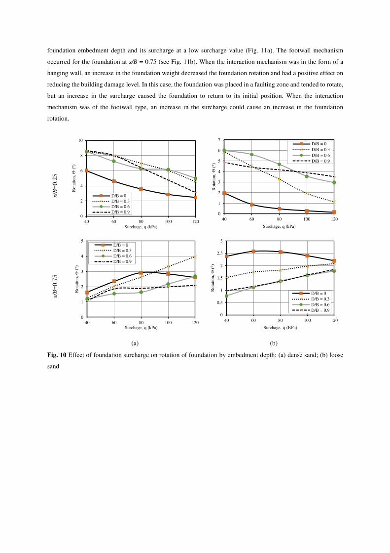
foundation embedment depth and its surcharge at a low surcharge value (Fig. 11a). The footwall mechanism
occurred for the foundation at s/B = 0.75 (see Fig. 11b). When the interaction mechanism was in the form of a
hanging wall, an increase in the foundation weight decreased the foundation rotation and had a positive effect on
reducing the building damage level. In this case, the foundation was placed in a faulting zone and tended to rotate,
but an increase in the surcharge caused the foundation to return to its initial position. When the interaction
mechanism was of the footwall type, an increase in the surcharge could cause an increase in the foundation
rotation.
s/B
=0
.25
s/B
=0
.75
(b) (a)
Fig. 10 Effect of foundation surcharge on rotation of foundation by embedment depth: (a) dense sand; (b) loose
sand
0
1
2
3
4
5
6
7
40 60 80 100 120
Ro
tati
on,
Ѳ(°
)
Surchage, q (kPa)
D/B = 0
D/B = 0.3
D/B = 0.6
D/B = 0.9
0
2
4
6
8
10
40 60 80 100 120
Rota
tion,
Ѳ(°
)
Surchage, q (kPa)
D/B = 0
D/B = 0.3
D/B = 0.6
D/B = 0.9
0
0.5
1
1.5
2
2.5
3
40 60 80 100 120
Ro
tati
on,
Ѳ(°
)
Surchage, q (KPa)
D/B = 0
D/B = 0.3
D/B = 0.6
D/B = 0.9
0
1
2
3
4
5
40 60 80 100 120
Ro
tati
on,
Ѳ(°
)
Surchage, q (kPa)
D/B = 0
D/B = 0.3
D/B = 0.6
D/B = 0.9

Fig. 11 Model deformation from fault-foundation interaction by foundation surcharge at D/B = 0.6 and α = 60°:
(a) s/B = 0.25; (b) s/B = 0.75
4.4 Effect of fault dip angle
The effect of the fault dip angle on the interaction of a normal fault rupture and shallow embedded foundation
were analyzed for rigid foundations at B = 10 m, surcharge q = 100 kPa, and D/B = 0, 0.3, 0.6 at s/B = 0.5 for both
dense and loose sands.
4.4.1 Vertical displacement profile at ground surface
The vertical displacement profiles at the ground surface, as a hazard caused by a normal fault rupture at dip angles
of α = 45°, 60°, and 90° and a fault throw of h/H = 5% for dense and loose sand, are shown in Fig. 12. The
existence of a graben is a hazard associated with normal faulting that forms between the main fault rupture and a
secondary rupture. As the fault dip angle increases, the width and depth of the graben will decrease because of the
to the declining formation of secondary ruptures in a high-angle dipping normal fault. For a normal α = 45° fault
with a foundation having an embedment depth of D/B = 0.6, a graben was created in both dense and loose sand at
widths of 1.12 and 1.3 H and depths of 0.02 and 0.008 H, respectively.
With an increase in the fault dip angle to 60°, a graben developed in dense sand, but not in loose sand.
With increases in the fault dip angle to 75° and 90°, no graben developed in any model. Based on the model
proposed by Cole and Lade (1984), at a dilation of α ≤45 + ψ/2 of the soil under normal faulting, a secondary
rupture developed in addition to the main rupture that resulted in the formation of a gravity block (graben) between
the rupture surfaces. Hazeghian and Soroush (2016) reported that a graben developed for a normal fault at α = 60°
in dense soil. The characteristics of the numerical models were not satisfied using the Cole and Lade (1984) model.
Dense, q= 40kPa
(a)
Dense, q= 100kPa
Loose, q= 40kPa
Loose, q= 100kPa
(b)
hangingwall +
gapping mechanism footwall
mechanism

Similarly to the free-field condition, the depth of the graben in dense sand was much greater than in loose
sand. This indicates that loose sand was capable of absorbing and dissipating fault-induced dislocation at the
ground surface. The width of the graben in loose sand was somewhat greater than in dense sand. This indicates
that the fault rupture propagated through the loose sand and diffused in the border zone around the foundation.
Fig. 12 Surface deformation due to fault-foundation interaction at different fault dip angles and embedment
depths at s/B = 0.5 and q = 100 kPa: (a) dense sand; (b) loose sand
4.4.2 Active and passive failure zones
Other consequences of a normal fault rupture-shallow embedded foundation interaction include active and passive
failure zones on the footwall and hanging wall sides of the foundation, respectively (left and right sides of the
foundation, respectively). These ruptures resulted from the rotation and translational displacement of the
foundation during the interaction with a normal fault rupture. Fig. 12 shows that a rupture zone of the active type

was created on the left side of the foundation for all dip angles with widths of 0.28 and 0.3 H in dense and loose
sand, respectively.
Figs. 13 and 14 show the plastic shear strain contours for the interaction of foundations with embedment
depths of D/B = 0.3 and 0.6 for normal faults having different dip angles. A graben is visible for the low-angle
dipping fault and the greater the fault dip angle, the lower the probability of the formation of a secondary rupture
and graben. Active ruptures fully mobilized in front of the left sidewall of the foundation, but a passive rupture
plane did not fully form on the right side (i.e. hanging wall). This could be attributed to the degree of rotation and
translation of the foundation sidewalls that mobilized the active and passive failure zones.
Fig. 13 Model deformed by fault-foundation interaction vs. fault dip angle at D/B = 0.3, s/B = 0.5, and q = 100
kPa: (a) dense sand; (b) loose sand
α=45°
α=60°
α=75°
α=90°
(a) (b)
zone A Zone GP
zone GP
zone GP
zone P
zone P
zone P
zone A
zone A
zone A
zone A
zone A
zone A
zone A
zone P
zone P
zone A: Active failure zone
zone GP: Graben and passive failure zone
zone P: Passive failure zone
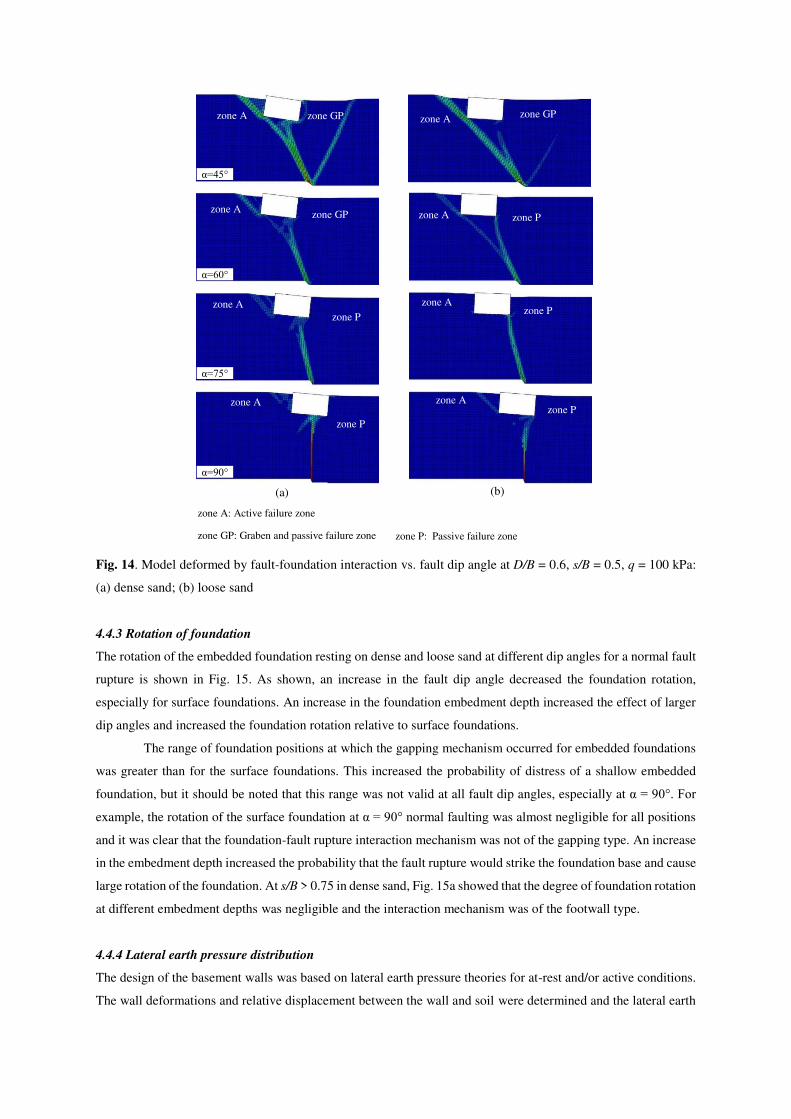
Fig. 14. Model deformed by fault-foundation interaction vs. fault dip angle at D/B = 0.6, s/B = 0.5, q = 100 kPa:
(a) dense sand; (b) loose sand
4.4.3 Rotation of foundation
The rotation of the embedded foundation resting on dense and loose sand at different dip angles for a normal fault
rupture is shown in Fig. 15. As shown, an increase in the fault dip angle decreased the foundation rotation,
especially for surface foundations. An increase in the foundation embedment depth increased the effect of larger
dip angles and increased the foundation rotation relative to surface foundations.
The range of foundation positions at which the gapping mechanism occurred for embedded foundations
was greater than for the surface foundations. This increased the probability of distress of a shallow embedded
foundation, but it should be noted that this range was not valid at all fault dip angles, especially at α = 90°. For
example, the rotation of the surface foundation at α = 90° normal faulting was almost negligible for all positions
and it was clear that the foundation-fault rupture interaction mechanism was not of the gapping type. An increase
in the embedment depth increased the probability that the fault rupture would strike the foundation base and cause
large rotation of the foundation. At s/B > 0.75 in dense sand, Fig. 15a showed that the degree of foundation rotation
at different embedment depths was negligible and the interaction mechanism was of the footwall type.
4.4.4 Lateral earth pressure distribution
The design of the basement walls was based on lateral earth pressure theories for at-rest and/or active conditions.
The wall deformations and relative displacement between the wall and soil were determined and the lateral earth
α=45°
α=60°
α=75°
α=90°
(a) (b)
zone A zone GP zone GP
zone GP
zone P
zone P
zone P
zone P
zone P
zone A
zone A
zone A
zone A
zone A
zone A
zone A
zone A: Active failure zone
zone GP: Graben and passive failure zone
zone P: Passive failure zone

pressure distribution on the wall was calculated. However, during faulting, the fault-induced displacement of the
soil and the wall appeared to be very large and the earth pressure distribution on the basement walls differed. To
examine the lateral earth pressure distribution on the basement walls during its interaction with a normal fault
rupture, the pressure distribution at the left and right sidewalls of the foundation at an embedment depth of D/B =
0.6, a surcharge of q = 100 kPa, and at s/B = 0.25, 0.5, and 0.75 for dense and loose soil are presented in Figs. 16
and 17.
Fig. 15 Rotation of foundation vs. fault dip angle and embedment depth at q = 100 kPa: (a) dense sand; (b) loose
sand
The analysis was carried out for normal fault dip angles of α = 45°, 60°, 75°, and 90° and a fault throw
of h/H = 5%. For the normal fault rupture-foundation interaction, it was clear that the condition of the left sidewall
was active and the right sidewall was passive; therefore, the lateral earth pressure distribution on both sides of the
wall was expected to adhere to these conditions. The lateral earth pressure distribution on the left sidewall shown
in Figs. 16a and 17a was distributed in an approximate triangular pattern and the active earth pressure was zero
in the upper parts of the wall due to the loss of contact between the soil and wall. The pressure values applied to
the wall were less than the Rankine active earth pressure. This could be attributed to large displacement of the soil
and a decrease in the height of a backfill subjected to the normal faulting and the post-peak state of the soil. At

some fault dip angles, the pressure either increased or decreased at specific positions. In particular, at a dip angle
of 45°, at s/B = 0.25, these fluctuations were intense and were greater than the active earth pressure at some
positions. In general, it would be conservative to assume an active or at-rest earth pressure for the design of the
footwall sidewall of an embedded foundation.
s/B
=0
.25
s/B
=0
.5
s/B
=0
.75
(b) (a)
Fig. 16 Earth pressure acting on foundation walls vs. fault dip angle at D/B = 0.6, q =100 kPa and dense sand: (a)
left sidewall of foundation; (b) right sidewall of foundation
-6
-5
-4
-3
-2
-1
0
0 100 200 300 400
Dep
th (
m)
Lateral earth pressure (kPa)
Pp, Rankine Theory P0, At rest
α=45° α=60°
α=75° α=90°
-6
-5
-4
-3
-2
-1
0
0102030405060
Dep
th (
m)
Lateral earth pressure (kPa)
P0, At rest Pa, Rankine Theory
α=45° α=60°
α=75° α=90°
-6
-5
-4
-3
-2
-1
0
0 100 200 300 400
Dep
th (
m)
Lateral earth pressure (kPa)
-6
-5
-4
-3
-2
-1
0
0102030405060
Dep
th (
m)
Lateral earth pressure (kPa)
-6
-5
-4
-3
-2
-1
0
0 100 200 300 400
Dep
th (
m)
Lateral earth pressure (kPa)
-6
-5
-4
-3
-2
-1
0
0102030405060
Dep
th (
m)
Lateral earth pressure (kPa)

s/B
=0
.25
s/B
=0
.5
s/B
=0
.75
(b) (a)
Fig. 17 Earth pressure acting on foundation walls vs. fault dip angle at D/B = 0.6, q = 100 kPa in loose sand: (a)
left sidewall of foundation; (b) right sidewall of foundation
The lateral earth pressure distribution on the right sidewall of the embedded foundation in Figs. 16b and
17b demonstrate that the applied pressure distribution was nonlinear and different from the triangular pattern of
the passive earth pressure from the Rankine theory. The pressure on the wall also was greater than the Rankine
passive earth pressure for the upper parts of the wall and lower at depths near the toe wall.
-6
-5
-4
-3
-2
-1
0
0 50 100 150 200 250 300
Dep
th (
m)
Lateral earth pressure (kPa)
Pp, Rankine Theory P0, At rest
α=45° α=60°
α=75° α=90°
-6
-5
-4
-3
-2
-1
0
01020304050
Dep
th (
m)
Lateral earth pressure (kPa)
P0, At rest Pa, Rankine Theory
α=45° α=60°
α=75° α=90°
-6
-5
-4
-3
-2
-1
0
0 50 100 150 200 250 300
Dep
th (
m)
Lateral earth pressure (kPa)
-6
-5
-4
-3
-2
-1
0
01020304050D
epth
(m
)
Lateral earth pressure (kPa)
-6
-5
-4
-3
-2
-1
0
0 50 100 150 200 250 300
Dep
th (
m)
Lateral earth pressure (kPa)
-6
-5
-4
-3
-2
-1
0
01020304050
Dep
th (
m)
Lateral earth pressure (kPa)

The passive earth pressure distribution for the right sidewall of the shallow embedded foundation creates
fundamental doubts. The schematic deformation of the shallow embedded foundation during its interaction with
normal faults with different dip angles is shown in Fig. 18. As seen, the deformations of the left and right sidewalls
were a combination of translational displacement and rotation about the toes of the sidewalls. The pressure
distribution on the wall that had rotated about its toe, as for James and Bransby (1971), was similar to the
distribution shown in Fig. 18b. Comparison of this distribution with those obtained from numerical modeling
indicated that the passive earth pressure distribution on the right sidewall was nonlinear and depended on the
extent of the foundation wall rotation about its toe. In addition, the magnitude of foundation rotation was
dependent on factors such as the fault dip angle, foundation embedment depth and its position, and the magnitude
of applied surcharges. Thus, the change in the rotation of the foundation wall indicate that the state of the soil may
have occurred for pre-peak, peak, and post-peak (i.e. residual) behavior, which would lead to a nonlinear pressure
distribution on the wall.
Fig. 18 Type of foundation rotation: (a) pattern of foundation rotation during normal fault interaction (s/B = 0.5,
q = 100 kPa, D/B = 0.6, dense sand), (b) expected wall stress distribution for wall rotation about its toe in dense
sand (James and Bransby 1971)
Left wall
Right wall
wall rotation
about its toe wall rotation
about its toe
(a)
(b) Top
Toe
Normal
stress
Top
Toe
Normal
stress
For small angle
of wall rotation For high angle
of wall rotation
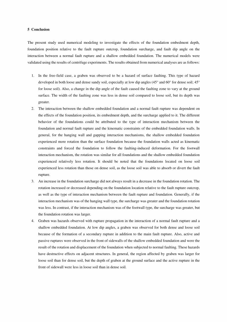
5 Conclusion
The present study used numerical modeling to investigate the effects of the foundation embedment depth,
foundation position relative to the fault rupture outcrop, foundation surcharge, and fault dip angle on the
interaction between a normal fault rupture and a shallow embedded foundation. The numerical models were
validated using the results of centrifuge experiments. The results obtained from numerical analyses are as follows:
1. In the free-field case, a graben was observed to be a hazard of surface faulting. This type of hazard
developed in both loose and dense sandy soil, especially at low dip angles (45° and 60° for dense soil; 45°
for loose soil). Also, a change in the dip angle of the fault caused the faulting zone to vary at the ground
surface. The width of the faulting zone was less in dense soil compared to loose soil, but its depth was
greater.
2. The interaction between the shallow embedded foundation and a normal fault rupture was dependent on
the effects of the foundation position, its embedment depth, and the surcharge applied to it. The different
behavior of the foundations could be attributed to the type of interaction mechanism between the
foundation and normal fault rupture and the kinematic constraints of the embedded foundation walls. In
general, for the hanging wall and gapping interaction mechanisms, the shallow embedded foundation
experienced more rotation than the surface foundation because the foundation walls acted as kinematic
constraints and forced the foundation to follow the faulting-induced deformation. For the footwall
interaction mechanism, the rotation was similar for all foundations and the shallow embedded foundation
experienced relatively less rotation. It should be noted that the foundations located on loose soil
experienced less rotation than those on dense soil, as the loose soil was able to absorb or divert the fault
rupture.
3. An increase in the foundation surcharge did not always result in a decrease in the foundation rotation. The
rotation increased or decreased depending on the foundation location relative to the fault rupture outcrop,
as well as the type of interaction mechanism between the fault rupture and foundation. Generally, if the
interaction mechanism was of the hanging wall type, the surcharge was greater and the foundation rotation
was less. In contrast, if the interaction mechanism was of the footwall type, the surcharge was greater, but
the foundation rotation was larger.
4. Graben was hazards observed with rupture propagation in the interaction of a normal fault rupture and a
shallow embedded foundation. At low dip angles, a graben was observed for both dense and loose soil
because of the formation of a secondary rupture in addition to the main fault rupture. Also, active and
passive ruptures were observed in the front of sidewalls of the shallow embedded foundation and were the
result of the rotation and displacement of the foundation when subjected to normal faulting. These hazards
have destructive effects on adjacent structures. In general, the region affected by graben was larger for
loose soil than for dense soil, but the depth of graben at the ground surface and the active rupture in the
front of sidewall were less in loose soil than in dense soil.
5. It should be noted that the differences in the rotation of a foundation subjected to a normal fault rupture at
different dip angles were dependent on the foundation position relative to the fault rupture outcrop, its
embedment depth, and the type of soil.
6. The triangular pressure distribution in accordance with Rankine theory can be used to design a good
approximation a left sidewall of embedded foundation (footwall side). However, the pressure distribution
on the right sidewall of the embedded foundation (hanging wall side) was not similar to the triangular
pressure distribution of the Rankine theory. It had a parabolic distribution that related to the magnitude of
foundation rotation and the state of the soil (peak or residual); thus, the patterns proposed by James and
Bransby (1971) could be applied.
Declarations
Not applicable
References
Agalianos A, Sieber M, Anastasopoulos I (2020) Cost‐effective analysis technique for the design of bridges
against strike‐slip faulting. EARTHQ ENG STRUCT D 49:1-21.
Ahmadi M, Moosavi M, Jafari MK (2018) Experimental investigation of reverse fault rupture propagation through
wet granular soil. ENG GEOL 239:229-240.
Anastasopoulos I, Gazetas G, Bransby MF, Davies MCR, El Nahas A (2007) Fault Rupture Propagation through
Sand: Finite-Element Analysis and Validation through Centrifuge Experiments.
J GEOTECH GEOENVIRON 133:943-958.
Anastasopoulos I, Callerio A, Bransby MF, Davies MCR., El Nahas A, Faccioli E, Rossignol E (2008) Numerical
analyses of fault–foundation interaction. BULL EARTHQ ENG 6:645-675.
Anastasopoulos I, Gazetas G, Bransby MF, Davies MC, and El Nahas A (2009) Normal fault rupture interaction
with strip foundations. J GEOTECH GEOENVIRON 135:359-370.
Ashtiani M, Ghalandarzadeh A, Towhata I (2015) Centrifuge modeling of shallow embedded foundations
subjected to reverse fault rupture. CAN GEOTECH J 53:505-519.
Ashtiani M, Ghalandarzadeh A (2020) Parameters affecting the interaction of shallow embedded foundations and
reverse faulting. BULL EARTHQ SCI ENG 7:21-36 (In Persian).
Azizkandi AS, Baziar MH, Ghavami S, Hasanaklou SH (2021) Use of Vertical and Inclined Walls to Mitigate the
Interaction of Reverse Faulting and Shallow Foundations: Centrifuge Tests and Numerical Simulation.
J GEOTECH GEOENVIRON 147:04020155.
Baziar MH, Nabizadeh A, Lee CJ, Hung WY (2014) Centrifuge modeling of interaction between reverse faulting
and tunnel. SOIL DYN EARTHQ ENG 65:151-164.
Baziar MH, Hasanaklou SH, Azizkandi AS (2019) Evaluation of EPS wall effectiveness to mitigate shallow
foundation deformation induced by reverse faulting. . BULL EARTHQ ENG 17:3095-3117.
Bransby MF, Davies MCR, El Nahas A (2008a) Centrifuge modeling of normal fault-footing interaction. BULL
EARTHQ ENG 6:585–605.
Bransby MF, Davies MCR, El Nahas A, Nagaoka S (2008b) Centrifuge modeling of reverse fault-foundation
interaction. . BULL EARTHQ ENG 6:607–628.

Bray JD, Seed RB, Seed HB (1994a) Analysis of earthquake fault rupture propagation through cohesive soil. J
GEOTECH ENG 120:562–580.
Bray JD, Seed RB, Seed HB (1994b) Analysis of earthquake fault rupture propagation through cohesive soil, J
GEOTECH ENG 120:562–580.
Cole DA, Lade PV (1984) Influence zones in alluvium over dip-slip faults. J GEOTECH ENG 110:599–615.
Dong JJ, Wang CD, Lee CT, Liao JJ, Pan YW (2003) The influence of surface ruptures on building damage in
the 1999Chi-Chi earthquake: a case study in Fengyuan City. ENG GEOL 71:157–179.
Faccioli E, Anastasopoulos I, Gazetas G, Callerio A, Paolucci R (2008) Fault rupture–foundation interaction:
selected case histories. . BULL EARTHQ ENG 6:557–583.
Fadaee M, Hashemi K, Farzaneganpour F, Anastasopoulos I, Gazetas G (2020) 3–storey building subjected to
reverse faulting: Analysis and experiments. SOIL DYN EARTHQ ENG 138:106297.
https://doi.org/10.1016/j.soildyn.2020.106297
Gazetas G, Pecker A, Faccioli E, Paolucci R, Anastasopoulos I (2008) Preliminary design recommendations for
dip-slip fault–foundation interaction. . BULL EARTHQ ENG 6:677–687.
Gudehus G, Nubel K (2004) Evolution of shear bands in sand. Geotechnique 54:187–201.
James RG, Bransby PL (1971) A velocity field for some passive earth pressure problems. GEOTECHNIQUE
21:61-83.
Lade PV, Cole DA, Cummings D (1984) Multiple failure surfaces over dip-slip faults. J GEOTECH ENG
110:616–627.
Lin A, Ren Z (2009) The Great Wenchuan earthquake of 2008: A photographic atlas of surface rupture and related
disaster. Springer Science and Business Media, Berlin
Lin ML, Chung CF, Jeng FS (2006) Deformation of overburden soil induced by thrust fault slip. ENG GEOL
88:70–89.
Loli M, Anastasopoulos I, Bransby MF, Ahmed W, Gazetas G (2011) Caisson Foundations subjected to Reverse
Fault Rupture: Centrifuge Testing and Numerical Analysis. J GEOTECH GEOENVIRON 137:914–925.
Loli M, Bransby MF, Anastasopoulos I, Gazetas G (2012) Interaction of caisson foundations with a seismically
rupturing normal fault: centrifuge testing versus numerical simulation. GEOTECHNIQUE 62:29-43.
Loukidis D, Bouckovalas GD, Papadimitriou AG (2009) Analysis of fault rupture propagation through uniform
soil cover, SOIL DYN EARTHQ ENG 29:1389–1404.
Muir Wood D (2002) Some observations of volumetric instabilities in soils. INT J SOLIDS STRUCT 39:3429–
3449.
Naeij M, Soroush A, Javanmardi Y (2019) Numerical investigation of the effects of embedment on the reverse
fault- foundation interaction. COMPUT GEOTECH 113:103098. https://doi.org/10.1016/j.
compgeo.2019.103098
Naeij M, Soroush A (2021) Comprehensive 3D numerical study on interaction between structure and dip-slip
faulting. SOIL DYN EARTHQ ENG 140:106285. https://doi.org/10.1016/j.soildyn.2020.106285.
Ng CWW, Cai QP, Hu P (2012) Centrifuge and Numerical Modeling of Normal Fault-Rupture Propagation in
Clay with and without a Preexisting Fracture. J GEOTECH GEOENVIRON 138:1492-1502.
Ni P, Qin X, Yi Y (2018) Use of tire-derived aggregate for seismic mitigation of buried pipelines under strike-
slip faults. SOIL DYN EARTHQ ENG 115:495-506.
Oettle NK, Bray JD (2016) Numerical Procedures for Simulating Earthquake Fault Rupture Propagation. INT J
GEOMECH 17:04016025. https://doi.org/10.1061/(ASCE)GM.1943-5622.0000661
Rasouli H, Fatahi B (2020) Geofoam blocks to protect buried pipelines subjected to strike-slip fault rupture.
GEOTEXT GEOMEMBR 48:257-274.
Rojhani M, Moradi M, Ghalandarzadeh A, Takada S (2012) Centrifuge modeling of buried continuous pipelines
subjected to reverse faulting. CAN GEOTECH J 49:659-670.
Sabagh M, Ghalandarzadeh A (2020a) Centrifuge experiments for shallow tunnels at active reverse fault
intersection. FRONT STRUCT CIV ENG 14:731-745.
Sabagh M, Ghalandarzadeh A (2020b) Centrifugal modeling of continuous shallow tunnels at active normal faults
intersection. TRANSP GEOTECH 22:100325. https://doi.org/10.1016/j.trgeo.2020.100325
Sadra V, Ghalandarzadeh A, Ashtiani M (2020) Use of a trench adjacent to a shallow foundation as a mitigation
measure for hazards associated with reverse faulting. ACTA GEOTECH 15:3167-3182.
Ulusay R, Aydan O, Hamada M (2002) the behavior of structures built on active fault zones: Examples from the
recent earthquakes of Turkey. STRUCT ENG EARTHQ ENG 19:149–167.
Yao C, Takemura J (2019) Using laser displacement transducer scanning technique in centrifuge modeling of
reverse fault–foundation interaction. SOIL DYN EARTHQ ENG 121:219-232.
Yao C, Takemura J, Guo W, Yan Q (2020a) Hyperbolic spiral model for predicting reverse fault ruptures in sand
based on centrifuge tests. GEOTECHNIQUE. http://doi.org/10.1680/jgeot.19.P.063
Yao C, Yan Q, Sun M, Dong W, Guo D (2020b) Rigid diaphragm wall with a relief shelf to mitigate the
deformations of soil and shallow foundations subjected to normal faulting. SOIL DYN EARTHQ ENG
137:106264. https://doi.org/10.1016/j.soildyn.2020.106264
Wells D, Copper smith K (1994) New empirical relations among magnitude, rupture length, rupture width, rupture
area and surface displacements. BULL SEISMOL SOC AM 84:974–1002.

Figures
Figure 1
Problem de�nition: (a) interaction between a normal fault rupture and shallow foundation with breadth B,embedment depth D, and surcharge q; (b) positions of shallow foundations relative to free-�eld faultrupture

Figure 2
Free-�eld normal faulting propagation at a dip angle of 60° through 2.16 m of Fontainebleau sand at Dr =60%: (a) deformed centrifuge model (Bransby et al. 2008a); (b) deformed numerical model; (c) verticaldisplacement pro�le at soil surface

Figure 3
Foundation-normal fault rupture interaction mechanism for B = 10 m, q = 37 kPa, S = 3.1 m, and h = 2.03m: (a) deformed centrifuge model (Bransby et al. 2008a); (b) deformed numerical model; (c) verticaldisplacement pro�le at ground surface; (d) rotation of foundation
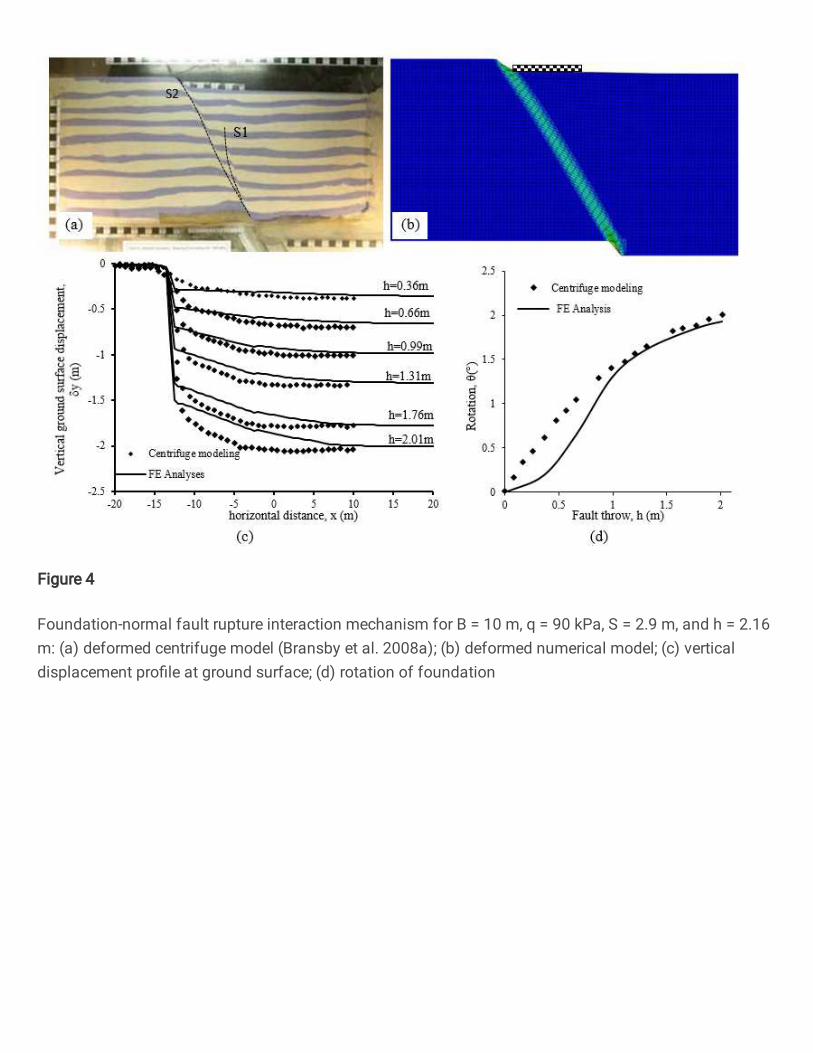
Figure 4
Foundation-normal fault rupture interaction mechanism for B = 10 m, q = 90 kPa, S = 2.9 m, and h = 2.16m: (a) deformed centrifuge model (Bransby et al. 2008a); (b) deformed numerical model; (c) verticaldisplacement pro�le at ground surface; (d) rotation of foundation

Figure 5
Vertical displacement pro�le at ground surface for normal free-�eld fault rupture with dip angles of 45°,60°, 75°, 90°: (a) dense sand; (b) loose sand

Figure 6
Rotation of foundation in terms of position vs. embedment depth: (a) dense sand; (b) loose sand
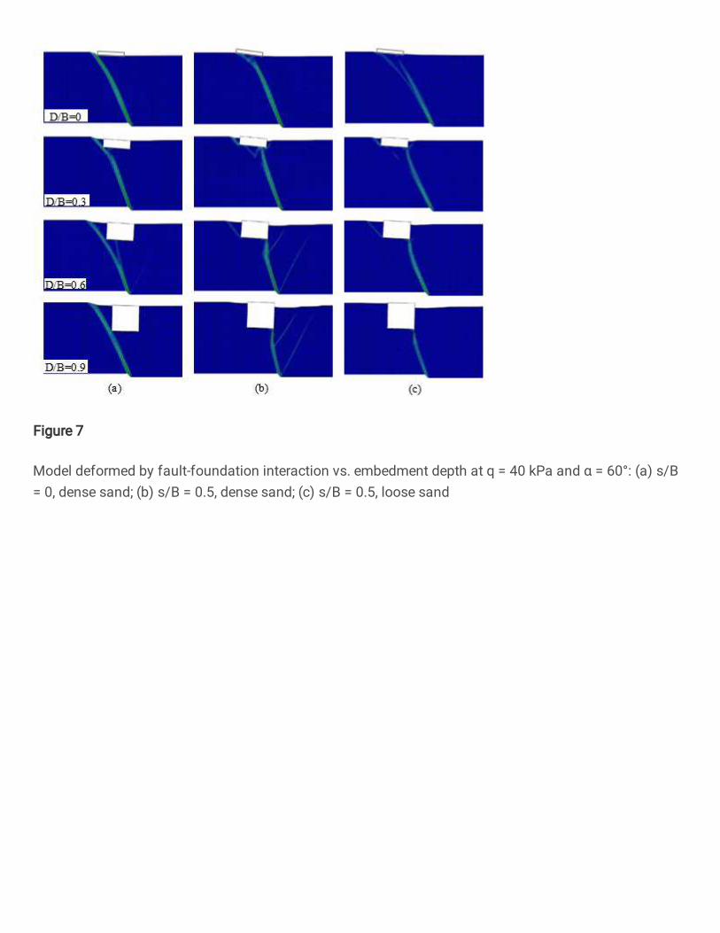
Figure 7
Model deformed by fault-foundation interaction vs. embedment depth at q = 40 kPa and α = 60°: (a) s/B= 0, dense sand; (b) s/B = 0.5, dense sand; (c) s/B = 0.5, loose sand

Figure 8
Model deformed by fault-foundation interaction vs. embedment depth at q = 100 kPa and α = 60°: (a) s/B= 0, dense sand; (b) s/B = 0.5, dense sand; (c) s/B = 0.5, loose sand

Figure 9
Normal fault rupture-shallow foundation interaction mechanisms: (a) dense sand; (b) loose sand

Figure 10
Effect of foundation surcharge on rotation of foundation by embedment depth: (a) dense sand; (b) loosesand
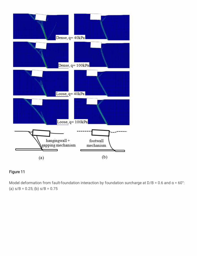
Figure 11
Model deformation from fault-foundation interaction by foundation surcharge at D/B = 0.6 and α = 60°:(a) s/B = 0.25; (b) s/B = 0.75
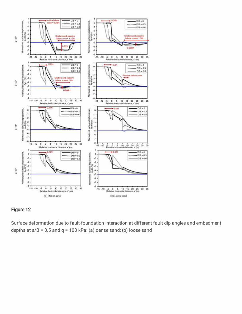
Figure 12
Surface deformation due to fault-foundation interaction at different fault dip angles and embedmentdepths at s/B = 0.5 and q = 100 kPa: (a) dense sand; (b) loose sand

Figure 13
Model deformed by fault-foundation interaction vs. fault dip angle at D/B = 0.3, s/B = 0.5, and q = 100kPa: (a) dense sand; (b) loose sand

Figure 14
Model deformed by fault-foundation interaction vs. fault dip angle at D/B = 0.6, s/B = 0.5, q = 100 kPa:(a) dense sand; (b) loose sand

Figure 15
Rotation of foundation vs. fault dip angle and embedment depth at q = 100 kPa: (a) dense sand; (b) loosesand

Figure 16
Earth pressure acting on foundation walls vs. fault dip angle at D/B = 0.6, q =100 kPa and dense sand:(a) left sidewall of foundation; (b) right sidewall of foundation

Figure 17
Earth pressure acting on foundation walls vs. fault dip angle at D/B = 0.6, q = 100 kPa in loose sand: (a)left sidewall of foundation; (b) right sidewall of foundation

Figure 18
Type of foundation rotation: (a) pattern of foundation rotation during normal fault interaction (s/B = 0.5,q = 100 kPa, D/B = 0.6, dense sand), (b) expected wall stress distribution for wall rotation about its toe indense sand (James and Bransby 1971)