NUMERICAL INVESTIGATIONS ON PARTICULAR … Paper_REVTN_no4_2017_Pasca_Sorin_UOra… ·...
6
33 Nonconventional Technologies Review 2017 Romanian Association of Nonconventional Technologies Romania, December, 2017 NUMERICAL INVESTIGATIONS ON PARTICULAR APPLICATION OF ELECTROMAGNETIC FORMING Sorin Pasca 1 and Alexandra Pasca 2 1 University of Oradea, Faculty of Electrical Engineering and Information Technology, [email protected] 2 Technical University of Cluj-Napoca, Faculty of Electrical Engineering, [email protected] ABSTRACT: The paper deals with numerical investigations on some special application derived from electromagnetic forming, such as pulse magnetic compaction of powder materials. Based on finite element models, it is computed the characteristic parameters and quantities of the process, in order to identifying the possibilities to improve the efficiency. It is evaluated the influence of the thickness of thin copper driver and of the stored energy in the capacitor bank. KEYWORDS: electromagnetic forming, electromagnetic compaction, numerical modeling, pulsed magnetic compaction 1. INTRODUCTION In the last few years, due to multiple advantages, the use of workpieces made by aluminum and its alloys has extended in many sectors e.g. in automotive industry. As a consequence, taking into account the particularities in processing such materials, some classical technologies are improved but, because these processes often are not satisfactory, new unconventional technologies are initiated and developed. High rate forming technologies such as electromagnetic forming, hydro-forming etc., used only in some special application in ’60-’70 and rarely used later, especially due to an insufficient control at that time, becomes in last decades actually. Electromagnetic forming or magnetoforming is a high speed forming process where a pulsed magnetic field is used to processing metals with high electrical conductivity (aluminum, copper or their alloys) within a few microseconds. Usually, thin wall metallic pieces (sheets, tubes) are deformed at room temperature by intense impulsive forces generated by a rapidly time varying magnetic field. But, as the ultra-fast electromagnetic deformation process was better controlled, the range of this type of applications has extended a lot. In the past few years, many scientific papers [1,2,3,4,5,6] analyses new processes such as electromagnetic impact welding or pulse-magnetic compaction of metal powder or of ceramic powder. After in previous work, we analyse different strategies in numerical modeling of magnetoforming process of thin wall metal sheets and tubes [7,8,9,10], in this paper we investigate the pulse- magnetic compaction of powder materials. The finite element model are build, having as a support the professional software Flux. The process is treated only as transient magnetic application. The intimate processes that take place in the powdered material when it is compressed are not taken into account. The main goal is to estimate the electromagnetic forces that act to compact the powder material. 2. MAGNETIC PULSED COMPACTION FACILITY Figure 2 presents the main elements of magnetic pulsed compaction equipment. The powder material (9) is placed into a rigid mold (8) and it will be pressed by a punch (7) provided with a flat cap (6). The flat coil (3) is supplied by adjacent electrical circuit, consisting in a capacitor bank capable to store enough amount of energy and a spark-gap as switching equipment. The charging of capacitors is ensured by a rectifier (13). Because the principle of pulse magnetic technologies requires a high conductivity material, a “driver” made by copper is placed as a layer on upper surface of cap punch (low conductivity steel). In fact, the driver is the active element, because in it are located the repulsive forces which are produced as a result of interaction between currents through coil turns and induced currents in copper driver. As the coil current can reach tens to hundreds kA, depending of stored energy and values of circuit parameters, the Lorentz forces can achieve very high values for a very short time (impulse). Between flat coil and driver is a thin layer of insulator, both electrical and thermal, e.g. mica based. The insulation between coil turns (2) can be made from an epoxy resin. The whole assembly is strengthened by two rigid frames, upper (1) and lower (10).
Transcript of NUMERICAL INVESTIGATIONS ON PARTICULAR … Paper_REVTN_no4_2017_Pasca_Sorin_UOra… ·...

33
Nonconventional Technologies Review 2017 Romanian Association of Nonconventional Technologies Romania, December, 2017
NUMERICAL INVESTIGATIONS ON PARTICULAR APPLICATION OF
ELECTROMAGNETIC FORMING
Sorin Pasca1 and Alexandra Pasca
2
1 University of Oradea, Faculty of Electrical Engineering and Information Technology, [email protected]
2 Technical University of Cluj-Napoca, Faculty of Electrical Engineering, [email protected]
ABSTRACT: The paper deals with numerical investigations on some special application derived from electromagnetic forming,
such as pulse magnetic compaction of powder materials. Based on finite element models, it is computed the characteristic
parameters and quantities of the process, in order to identifying the possibilities to improve the efficiency. It is evaluated the
influence of the thickness of thin copper driver and of the stored energy in the capacitor bank.
KEYWORDS: electromagnetic forming, electromagnetic compaction, numerical modeling, pulsed magnetic compaction
1. INTRODUCTION
In the last few years, due to multiple advantages, the
use of workpieces made by aluminum and its alloys
has extended in many sectors e.g. in automotive
industry. As a consequence, taking into account the
particularities in processing such materials, some
classical technologies are improved but, because
these processes often are not satisfactory, new
unconventional technologies are initiated and
developed.
High rate forming technologies such as
electromagnetic forming, hydro-forming etc., used
only in some special application in ’60-’70 and
rarely used later, especially due to an insufficient
control at that time, becomes in last decades
actually.
Electromagnetic forming or magnetoforming is a
high speed forming process where a pulsed magnetic
field is used to processing metals with high electrical
conductivity (aluminum, copper or their alloys)
within a few microseconds. Usually, thin wall
metallic pieces (sheets, tubes) are deformed at room
temperature by intense impulsive forces generated
by a rapidly time varying magnetic field.
But, as the ultra-fast electromagnetic deformation
process was better controlled, the range of this type
of applications has extended a lot. In the past few
years, many scientific papers [1,2,3,4,5,6] analyses
new processes such as electromagnetic impact
welding or pulse-magnetic compaction of metal
powder or of ceramic powder.
After in previous work, we analyse different
strategies in numerical modeling of magnetoforming
process of thin wall metal sheets and tubes
[7,8,9,10], in this paper we investigate the pulse-
magnetic compaction of powder materials. The finite
element model are build, having as a support the
professional software Flux. The process is treated
only as transient magnetic application. The intimate
processes that take place in the powdered material
when it is compressed are not taken into account.
The main goal is to estimate the electromagnetic
forces that act to compact the powder material.
2. MAGNETIC PULSED COMPACTION
FACILITY
Figure 2 presents the main elements of magnetic
pulsed compaction equipment. The powder material
(9) is placed into a rigid mold (8) and it will be
pressed by a punch (7) provided with a flat cap (6).
The flat coil (3) is supplied by adjacent electrical
circuit, consisting in a capacitor bank capable to
store enough amount of energy and a spark-gap as
switching equipment. The charging of capacitors is
ensured by a rectifier (13).
Because the principle of pulse magnetic
technologies requires a high conductivity material, a
“driver” made by copper is placed as a layer on
upper surface of cap punch (low conductivity steel).
In fact, the driver is the active element, because in it
are located the repulsive forces which are produced
as a result of interaction between currents through
coil turns and induced currents in copper driver. As
the coil current can reach tens to hundreds kA,
depending of stored energy and values of circuit
parameters, the Lorentz forces can achieve very high
values for a very short time (impulse). Between flat
coil and driver is a thin layer of insulator, both
electrical and thermal, e.g. mica based. The
insulation between coil turns (2) can be made from
an epoxy resin. The whole assembly is strengthened
by two rigid frames, upper (1) and lower (10).

34
Figure 1. Main components of facility used for pulsed magnetic compaction of powder materials. 1 – upper frame, 2 – electrical
insulation between coil turns, 3 – coil turns, 4 - electrical insulation between coil and driver, 5 – driver sheet made by high
conductivity metal, 6 – cap, 7 – punch, 8 – mold, 9, compacted powder material, 10 – lower frame,11 – capacitor bank, 12 – spark
gap, 13 – rectifier
.
3. THEORETICAL BACKGROUND
The pulsed magnetic compaction device presented
above can be considered, with a sufficiently good
approximation, as having axial symmetry.
Consequently, this system with axisymmetric
geometry can be studied in 2D, in rOz coordonate
system. As we stated in the introduction, only
transient magnetic problem are analysed, neglecting
in this case the effects generated by temperature rise
in coil and driver, as well as the complex mechanical
phenomena related to powder compaction. In
previous works we studied the coupling
electromagnetic – thermal – mechanical phenomena,
by treating electromagnetic forming processes as a
multiphysics applications [7,8,9,10].
The current density in the coil, that is the source of
electromagnetic field, has azimuthally orientation,
Jex = Jex . As a consequence, the time dependent
magnetic vector potential A(r, z, t) has component
only in the same direction. The governing equation
in terms of A is:
exDt
D
zz)r(
rrrJ
AAA
(1)
where is magnetic reluctivity and = 1/ is
electric conductivity. The total derivative in (1) has
the expression AAA
rotvtDt
D
, with v the
35
velocity. If the motion is not considered (v=0) the
equation of the vector potential in rA is:
ex)r(tr
1)r(
zrz)r(
rrrJAAA
(2)
The second term in the left part of the equation
represents the density of induced currents, non-null
in the conductive regions of the study domain. This
equation of state variable A of transient magnetic
field is solved using the step by step in time domain
method. The 2D electromagnetic computation
domain for the magnetic compacting application, in
which the device has axial symmetry, is shown in
Figure 2.
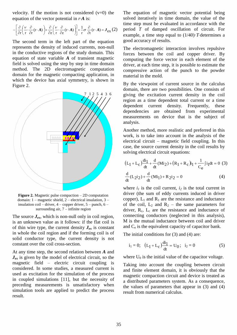
Figure 2. Magnetic pulse compaction – 2D computation
domain: 1 – magnetic shield, 2 – electrical insulation, 3 –
insulation coil – driver, 4 – copper driver, 5 – punch, 6 –
surrounding air, 7 – infinite region
The source Jex, which is non-null only in coil region,
is an unknown value as it follows: if the flat coil is
of thin wire type, the current density Jex is constant
in whole the coil region and if the forming coil is of
solid conductor type, the current density is not
constant over the coil cross-section.
At any time step, the second relation between A and
Jex is given by the model of electrical circuit, so the
magnetic field – electric circuit coupling is
considered. In some studies, a measured current is
used as excitation for the simulation of the process
in coupled simulations [11], but the necessity of
preceding measurements is unsatisfactory when
simulation tools are applied to predict the process
result.
The equation of magnetic vector potential being
solved iteratively in time domain, the value of the
time step must be evaluated in accordance with the
period T of damped oscillation of circuit. For
example, a time step equal to (1/40)·Tdetermines a
good accuracy of results.
The electromagnetic interaction involves repulsive
forces between the coil and copper driver. By
computing the force vector in each element of the
driver, at each time step, it is possible to estimate the
compressive action of the punch to the powder
material in the mold.
By the viewpoint of current source in the calculus
domain, there are two possibilities. One consists of
giving the excitation current density in the coil
region as a time dependent total current or a time
dependent current density. Frequently, these
dependencies are obtained from experimental
measurements on device that is the subject of
analysis.
Another method, more realistic and preferred in this
work, is to take into account in the analysis of the
electrical circuit – magnetic field coupling. In this
case, the source current density in the coil results by
solving electrical circuit equations:
0dt1ieC
11icR1R)2Mi(
dt
d
dt
1dicL1L (3)
02i2R)1Mi(dt
d)2i2L(
dt
d (4)
where i1 is the coil current, i2 is the total current in
driver (the sum of eddy currents induced in driver
copper), L1 and R1 are the resistance and inductance
of the coil, L2 and R2 – the same parameters for
driver, Rc, Lc are the resistance and inductance of
connecting conductors (neglected in this analysis),
M is the mutual inductance between coil and driver
and Ce is the equivalent capacity of capacitor bank.
The initial conditions for (3) and (4) are:
i1 = 0; 0Udt
1dicL1L ; i2 = 0 (5)
where U0 is the initial value of the capacitor voltage.
Taking into account the coupling between circuit
and finite element domain, it is obviously that the
magnetic compaction circuit and device is treated as
a distributed parameters system. As a consequence,
the values of parameters that appear in (3) and (4)
result from numerical calculus.
1 2 5 4 3 6 7

36
Figure 3. Details of the mesh of computation domain
Figure 3 shows the mesh details that must be
adapted to current density distribution. In the
massive conductor regions, for accurate results it is
important to have at least two finite elements along
to skin depth of electromagnetic field. This must be
verified in accordance with frequency reached in
discharging process.
4. THE APPLICATION AND RESULTS
The application consists of a parametrical study of
electromagnetic transient regime associated with the
pulsed magnetic compaction process. The
parameters of the model that can by modified in the
study are presented in Table 1 ..
Table 1. The parameters of the model
No. Parameter name Parameter signification Initial value
1. ASPIRA radial dimension of cross-section of turn coil 5 mm
2. BSPIRA radial dimension of cross-section of turn coil 10 mm
3. HDRIVER thickness of copper driver 5 mm
4. HMICA thickness of insulation between flat coil and driver 2 mm
5. INTRESP thickness of insulation between coil turns in radial direction 5 mm
6. GROSECRAN thickness of magnetic shield (optional) 16 mm
7. DINTIND inner diameter of the coil 20 mm
8. DDOP diameter of punch 40 mm
9. HDOP the axial dimension of punch 40 mm
10. HCAPDOP the axial dimension of punch cap 10 mm
11. C equivalent capacitance of capacitor bank 200 F
12. V0 initial voltage of capacitor bank 1000 V
For the initial values of model parameters given in
Table 1, Figure 4 presents the time variation of
capacitor voltage and of the coil current, as well as
the lines of magnetic flux and the chart of flax
density at the time of 9 s, when the current riches
the maximum value of 27.52 kA. It is observed that
on the upper surface of the driver, for a very short
time, it is obtained values of flux density greater
than 4 T. At this moment of maximum current
through the coil, the chart of current density in
driver and the distribution of volume density of
electromagnetic force is illustrated in Figure 5.
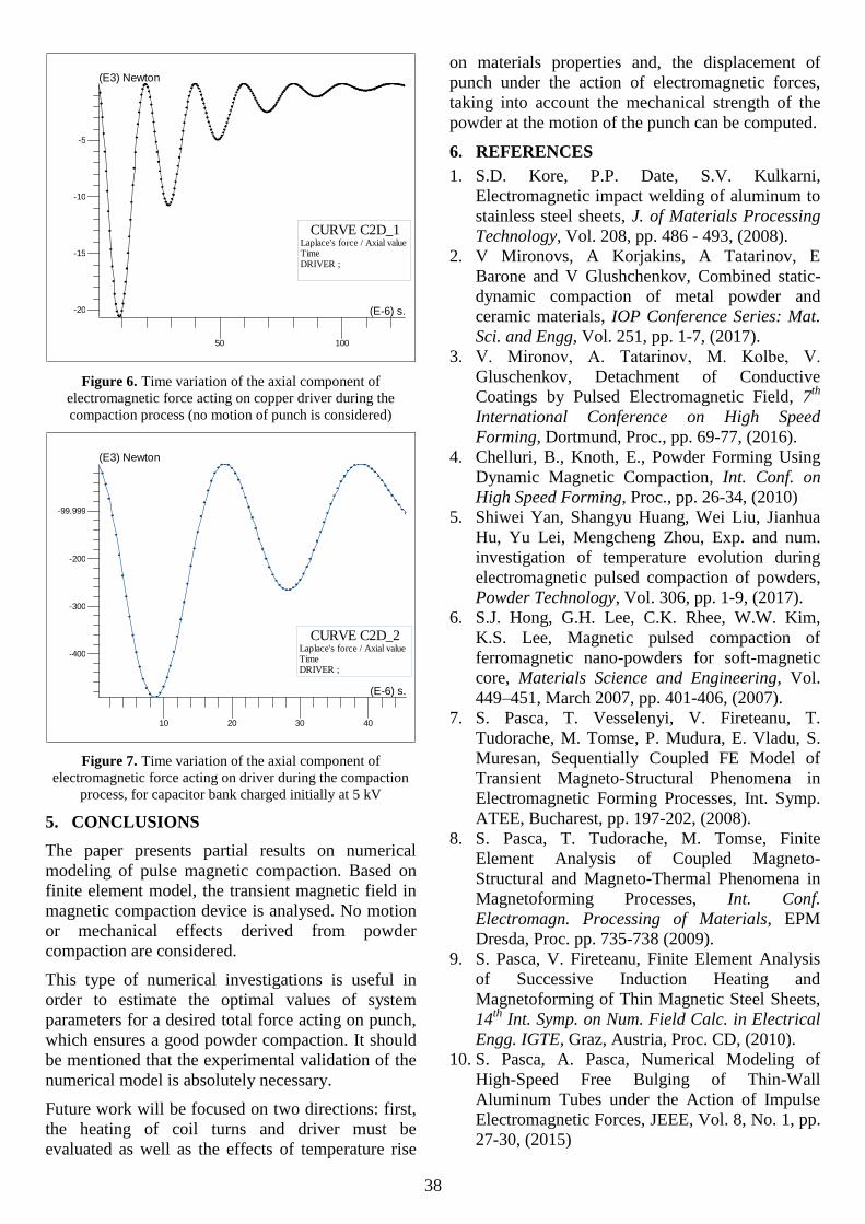
The computation of the axial component of the total
force acting on driver at the moment of maximum
current through the coil give the value of 20.64 kN.
Figure 6 presents the time variation of the axial
component of electromagnetic force acting on
copper driver during the capacitor discharge process,
assuming that no motion is produced, i.e. the punch
remains in the initial position. Finally, Figure 7
shows the same variation of axial components of
force, obtained for the capacitor bank with the same
capacitance but charged initially at voltage of 5 kV.
In this case, the resulting forces are much bigger, as
it is expected.
It is obvious that the parameters that give the energy
of the process will be chosen in accordance with
characteristics of powder material.
Another observation it’s about mechanical stress
acting on punch cap. Based on simulation, we can
choose the geometry and the thickness to avoiding
its destruction.

37
Figure 4. Time variation of capacitor voltage (a) and coil current (b). Equiflux lines (c) and chart of flux density (d) at the moment
when coil current reaches its maximum value
Figure 5. The chart of current density in copper driver (a) and the vectorial representation of volume density of electromagnetic
force acting on the driver at the moment of maximum current through the coil
SINT1
-500
0
500
50 100
(E-6) s.
VoltCURVE C2D_2
Circuit / VoltageTimeC1 ;
SINT1
-10
0
9.999
20
50 100
(E-6) s.
(E3) Ampere
CURVE C2D_1Circuit / CurrentTimeM1 ;
Isovalues ResultsQuantity : Equi flux Weber Time (s.) : 9E-6Line / Value 1 / 22.17534E-6 2 / 239.50099E-6 3 / 456.82667E-6 4 / 674.15234E-6 5 / 891.47798E-6 6 / 1.1088E-3 7 / 1.32613E-3 8 / 1.54345E-3 9 / 1.76078E-3 10 / 1.97811E-3 11 / 2.19543E-3
Color Shade ResultsQuantity : |Flux density| Tesla Time (s.) : 9E-6Scale / Color4.11472E-12 / 308.11352E-3308.11352E-3 / 616.22703E-3616.22703E-3 / 924.34055E-3924.34055E-3 / 1.232451.23245 / 1.540571.54057 / 1.848681.84868 / 2.156792.15679 / 2.464912.46491 / 2.773022.77302 / 3.081143.08114 / 3.389253.38925 / 3.697363.69736 / 4.005484.00548 / 4.313594.31359 / 4.62174.6217 / 4.92982
Color Shade ResultsQuantity : Current density A/(square mm) Time (s.) : 9E-6Scale / Color-5.94843E3 / -5.57665E3-5.57665E3 / -5.20487E3-5.20487E3 / -4.8331E3-4.8331E3 / -4.46132E3-4.46132E3 / -4.08954E3-4.08954E3 / -3.71777E3-3.71777E3 / -3.34599E3-3.34599E3 / -2.97421E3-2.97421E3 / -2.60244E3-2.60244E3 / -2.23066E3-2.23066E3 / -1.85888E3-1.85888E3 / -1.48711E3-1.48711E3 / -1.11533E3-1.11533E3 / -743.55347-743.55347 / -371.77673-371.77673 / 0
Region vectors resultsQuantity : JxB N/m3 Time (s.) : 9E-6 Max vector value : 3.915711e+011
38
Figure 6. Time variation of the axial component of
electromagnetic force acting on copper driver during the
compaction process (no motion of punch is considered)
Figure 7. Time variation of the axial component of
electromagnetic force acting on driver during the compaction
process, for capacitor bank charged initially at 5 kV
5. CONCLUSIONS
The paper presents partial results on numerical
modeling of pulse magnetic compaction. Based on
finite element model, the transient magnetic field in
magnetic compaction device is analysed. No motion
or mechanical effects derived from powder
compaction are considered.
This type of numerical investigations is useful in
order to estimate the optimal values of system
parameters for a desired total force acting on punch,
which ensures a good powder compaction. It should
be mentioned that the experimental validation of the
numerical model is absolutely necessary.
Future work will be focused on two directions: first,
the heating of coil turns and driver must be
evaluated as well as the effects of temperature rise
on materials properties and, the displacement of
punch under the action of electromagnetic forces,
taking into account the mechanical strength of the
powder at the motion of the punch can be computed.
6. REFERENCES
1. S.D. Kore, P.P. Date, S.V. Kulkarni,
Electromagnetic impact welding of aluminum to
stainless steel sheets, J. of Materials Processing
Technology, Vol. 208, pp. 486 - 493, (2008).
2. V Mironovs, A Korjakins, A Tatarinov, E
Barone and V Glushchenkov, Combined static-
dynamic compaction of metal powder and
ceramic materials, IOP Conference Series: Mat.
Sci. and Engg, Vol. 251, pp. 1-7, (2017).
3. V. Mironov, А. Tatarinov, М. Kolbe, V.
Gluschenkov, Detachment of Conductive
Coatings by Pulsed Electromagnetic Field, 7th
International Conference on High Speed
Forming, Dortmund, Proc., pp. 69-77, (2016).
4. Chelluri, B., Knoth, E., Powder Forming Using
Dynamic Magnetic Compaction, Int. Conf. on
High Speed Forming, Proc., pp. 26-34, (2010)
5. Shiwei Yan, Shangyu Huang, Wei Liu, Jianhua
Hu, Yu Lei, Mengcheng Zhou, Exp. and num.
investigation of temperature evolution during
electromagnetic pulsed compaction of powders,
Powder Technology, Vol. 306, pp. 1-9, (2017).
6. S.J. Hong, G.H. Lee, C.K. Rhee, W.W. Kim,
K.S. Lee, Magnetic pulsed compaction of
ferromagnetic nano-powders for soft-magnetic
core, Materials Science and Engineering, Vol.
449–451, March 2007, pp. 401-406, (2007).
7. S. Pasca, T. Vesselenyi, V. Fireteanu, T.
Tudorache, M. Tomse, P. Mudura, E. Vladu, S.
Muresan, Sequentially Coupled FE Model of
Transient Magneto-Structural Phenomena in
Electromagnetic Forming Processes, Int. Symp.
ATEE, Bucharest, pp. 197-202, (2008).
8. S. Pasca, T. Tudorache, M. Tomse, Finite
Element Analysis of Coupled Magneto-
Structural and Magneto-Thermal Phenomena in
Magnetoforming Processes, Int. Conf.
Electromagn. Processing of Materials, EPM
Dresda, Proc. pp. 735-738 (2009).
9. S. Pasca, V. Fireteanu, Finite Element Analysis
of Successive Induction Heating and
Magnetoforming of Thin Magnetic Steel Sheets,
14th
Int. Symp. on Num. Field Calc. in Electrical
Engg. IGTE, Graz, Austria, Proc. CD, (2010).
10. S. Pasca, A. Pasca, Numerical Modeling of
High-Speed Free Bulging of Thin-Wall
Aluminum Tubes under the Action of Impulse
Electromagnetic Forces, JEEE, Vol. 8, No. 1, pp.
27-30, (2015)
SINT1
-20
-15
-10
-5
50 100
(E-6) s.
(E3) Newton
CURVE C2D_1Laplace's force / Axial valueTimeDRIVER ;
SINT1
-400
-300
-200
-99.999
10 20 30 40
(E-6) s.
(E3) Newton
CURVE C2D_2Laplace's force / Axial valueTimeDRIVER ;


![Application of pulsed electromagnetic energy[1]konsys-t.tanger.cz/files/proceedings/metal_08/Lists/... · 2011-10-11 · diagrams, are documented for these EM forming methods Figure](https://static.fdocuments.us/doc/165x107/5f5047ef04bee225b90c8bc7/application-of-pulsed-electromagnetic-energy1konsys-t-2011-10-11-diagrams.jpg)