NUMERICAL ANALYSIS OF THE VOID EVOLUTION …imim.pl/files/archiwum/Vol3_2009/2.pdf · numerical...
8
A R C H I V E S O F M E T A L L U R G Y A N D M A T E R I A L S Volume 54 2009 Issue 3 P. LACKI * NUMERICAL ANALYSIS OF THE VOID EVOLUTION DURING METAL PLASTIC DEFORMATION ANALIZA NUMERYCZNA EWOLUCJI NIECIĄGLOŚCI MATERIALOWEJ PODCZAS DEFORMACJI PLASTYCZNEJ Quality of the die forgings essentially depends on the material defects (voids) and possibilities of their correction during the forging process. Material defects cause unfavourable plastic strain distribution in the forging volume. In case of precise forging the defects also have impact on the precision of forging geometry. In the paper a numerical simulation of the material void influence on the die forging process has been presented. Two first operations of the die forging process, i.e. upsetting and preparing have been analysed. Numerical calculations have been made with the ADINA System based on the Finite Element Method. Elastic properties of the dies made from hot-work tool steel and elastic-plastic properties of the deformed material (LH15 bearing steel) have been assumed in the numerical model. For the sake of axial symmetry the model has been simplified. On the basis of numerical simulation analysis the possible way of solving some problems occurring during design of die forging process will be presented. Keywords: defects, die forging, numerical simulation Jakość odkuwek matrycowych wdużej mierze zależy od występujących defektów (nieciąglości) materialowych i możliwo- ści ich korekcji podczas procesu kucia. Nieciąglości materialowe wywolują niekorzystny rozklad odksztalceń plastycznych w objętości odkuwki. W przypadku kucia dokladnego wady materialowe mają również wplyw na dokladność geometrii odkuwki. W artykule zaprezentowano symulację numeryczną wplywu nieciąglości materialowej na proces kucia. Przeanalizowano dwie pierwsze operacje kucia tj. spęczanie i kucie wstępne. Obliczenia numeryczne wykonano za pomocą programu ADINA System opartego na metodzie elementów skończonych. W modelu numerycznym przyjęto wlaściwości sprężyste dla materialu matrycy, wykonanej ze stali narzędziowej do pracy na gorąco oraz sprężysto-plastyczne dla materialu odkuwki (stal lożyskowa LH15). Ze względu na osiową symetrię modelu przyjęto pewne uproszczenia. Na podstawie analizy symulacji numerycznej przedstawiono możliwości rozwiązywania niektórych problemów występujących podczas kucia matrycowego. 1. Introduction The growing demands for high quality products forces forgings producers to put more emphasis on the quality aspects and fulfilment of the ISO standard re- quirements. Such a situation increases the effort spent on identification of defects and explanation of their causes. Quality of the die forgings essentially depends on the material defects and possibilities of their correction dur- ing the forging process. The characteristic longitudinal and transverse cracks are the most often defects arising during solidification and cooling of ingot. The cracks result from shrinkage stresses exceeding steel strength. Analysis of causes and effects of the defects poses a com- plex problem. Predictions how the material void will be- have during forming process is especially difficult. Mate- rial defects (voids) can cause unfavourable plastic strain distribution in the forging volume. In case of precise forging the defects also have impact on the precision of forging geometry. Figure 1, for example, shows a mate- rial discontinuity defect. Fig. 1. An example of material discontinuities * CZĘSTOCHOWA UNIVERSITY OF TECHNOLOGY, INSTITUTE OF METAL FORMING, QUALITY ENGINEERING AND BIOENGINEERING, 42-200 CZĘSTOCHOWA, 21 ARMII KRAJOWEJ AV., POLAND
Transcript of NUMERICAL ANALYSIS OF THE VOID EVOLUTION …imim.pl/files/archiwum/Vol3_2009/2.pdf · numerical...

A R C H I V E S O F M E T A L L U R G Y A N D M A T E R I A L S
Volume 54 2009 Issue 3
P. LACKI∗
NUMERICAL ANALYSIS OF THE VOID EVOLUTION DURING METAL PLASTIC DEFORMATION
ANALIZA NUMERYCZNA EWOLUCJI NIECIĄGŁOŚCI MATERIAŁOWEJ PODCZAS DEFORMACJI PLASTYCZNEJ
Quality of the die forgings essentially depends on the material defects (voids) and possibilities of their correction duringthe forging process. Material defects cause unfavourable plastic strain distribution in the forging volume. In case of preciseforging the defects also have impact on the precision of forging geometry. In the paper a numerical simulation of the materialvoid influence on the die forging process has been presented. Two first operations of the die forging process, i.e. upsetting andpreparing have been analysed. Numerical calculations have been made with the ADINA System based on the Finite ElementMethod. Elastic properties of the dies made from hot-work tool steel and elastic-plastic properties of the deformed material(ŁH15 bearing steel) have been assumed in the numerical model. For the sake of axial symmetry the model has been simplified.On the basis of numerical simulation analysis the possible way of solving some problems occurring during design of die forgingprocess will be presented.
Keywords: defects, die forging, numerical simulation
Jakość odkuwek matrycowych w dużej mierze zależy od występujących defektów (nieciągłości) materiałowych i możliwo-ści ich korekcji podczas procesu kucia. Nieciągłości materiałowe wywołują niekorzystny rozkład odkształceń plastycznych wobjętości odkuwki. W przypadku kucia dokładnego wady materiałowe mają również wpływ na dokładność geometrii odkuwki.W artykule zaprezentowano symulację numeryczną wpływu nieciągłości materiałowej na proces kucia. Przeanalizowano dwiepierwsze operacje kucia tj. spęczanie i kucie wstępne. Obliczenia numeryczne wykonano za pomocą programu ADINA Systemopartego na metodzie elementów skończonych. W modelu numerycznym przyjęto właściwości sprężyste dla materiału matrycy,wykonanej ze stali narzędziowej do pracy na gorąco oraz sprężysto-plastyczne dla materiału odkuwki (stal łożyskowa ŁH15). Zewzględu na osiową symetrię modelu przyjęto pewne uproszczenia. Na podstawie analizy symulacji numerycznej przedstawionomożliwości rozwiązywania niektórych problemów występujących podczas kucia matrycowego.
1. Introduction
The growing demands for high quality productsforces forgings producers to put more emphasis on thequality aspects and fulfilment of the ISO standard re-quirements. Such a situation increases the effort spent onidentification of defects and explanation of their causes.Quality of the die forgings essentially depends on thematerial defects and possibilities of their correction dur-ing the forging process. The characteristic longitudinaland transverse cracks are the most often defects arisingduring solidification and cooling of ingot. The cracksresult from shrinkage stresses exceeding steel strength.Analysis of causes and effects of the defects poses a com-plex problem. Predictions how the material void will be-have during forming process is especially difficult. Mate-rial defects (voids) can cause unfavourable plastic strain
distribution in the forging volume. In case of preciseforging the defects also have impact on the precision offorging geometry. Figure 1, for example, shows a mate-rial discontinuity defect.
Fig. 1. An example of material discontinuities
∗ CZĘSTOCHOWA UNIVERSITY OF TECHNOLOGY, INSTITUTE OF METAL FORMING, QUALITY ENGINEERING AND BIOENGINEERING, 42-200 CZĘSTOCHOWA, 21 ARMII KRAJOWEJ AV.,POLAND

568
In the paper an attempt has been made to assessthe possibilities of simulation and prediction of the re-sults of the material void during precise forging process.The numerical simulation results of void evolution dur-ing plastic deformation of ŁH15 bearing steel in twoforging operations have been presented. On the basis ofnumerical simulation analysis of the die forging process,taking into account material defects, the possible wayof solving the problems occurring during design of dieforging process was presented.
2. Numerical model
A rolling bearing, shown in Figure 2 was analysedin the numerical simulation. Two first forging operations,i.e. upsetting and preparing were modelled. Numerical
calculations had been made with the ADINA Systemusing Finite Element Method. Figure 3 shows the nu-merical model of the upsetting process. For the sake ofan axial symmetry of the problem 2D axial-symmetricalmodel of the process has been assumed. Numerical mod-el had 19614 nodes and 4752 square 8-node elements.
Fig. 2. A view of the analysed rolling bearing
Fig. 3. MES numerical model; a) the forging with a defect before deformation, b) the forging with a defect after deformation, c) the forgingwith no defect before deformation, d) the forging with no defect after deformation
Two following variants of the forging process wereanalysed: forging without any defects and forging witha defect. Figure 2a) and 2b) present the finite elementmesh for the tools and forging with the defect, adequate-ly, before and after the forging process while Figure 2c)and 2d) present the finite element mesh for the forgingwithout any defect. An isothermal course of the processand Coulomb frictional model on the contact surface be-tween the forging and tools have been assumed. Frictioncoefficient was µ = 0.2. The same frictional model but
friction coefficient µ = 0.25 were assumed for the contactzone between defect surfaces. The tool was made fromWCL hot-work tool steel and the forging was made fromŁH15 bearing steel.
569
TABLE 1Chemical constitution of the materials
chemical constitution [%]
C Mn Si Cr Mo V FeTool 0.4 0.4 1.0 5.0 1.3 0.3 balance
[WCL]
Forging 0.95-1.1 0.25-0.45 0.15-0.35 1.3-1.65 – – balance[ŁH15]
Though the real material defects are irregular, in
the simulation material discontinuity was modelled asa three-pointed star (see Fig. 4) with the arms directedat the angle of 0, 45 and 90◦ to the direction of thetool motion. Such a defect location allows investigatingthe results of the forging process depending on the defectposition in the slug forging. In order to better calculationprecise the finite element mesh was thickened in the areaof the defect (in places its initial shape was irregular).
Fig. 4. Defect geometyry: a) a location of the defect in the slug forging, b) defect dimendions [mm]
3. Calculation results and discussion
Figures 5, 6, and 7 show defect geometry after thesubsequent forging operations with the marked lines ofmaterial flow in the defect area. Figure 5a shows a toolposition in relation to the forging in t=0s. The defectoutline was marked schematically. Figure 5b shows theinitial lines of the material flow. A, B,C letters describ-ing the characteristic areas and A1, A2, B1, B2, C1, C2ones describing the appropriate edges were introduced in
order to better description of changes occurring in thedefect area.

570
Fig. 5. An initial geometry of the defect: a) scheme of the deformation with a defect, b) lines of the material flow in the defect area
Fig. 6. Defect geometry after upsetting operation t = 0.5s; a) scheme of deformation with the defect b) material flow lines in the defect area
Upsetting of the slug forging to the height ofh=16mm is the first operation of the analysed process.During this operation the defect closes. The individualdefect surfaces get contact and void disappear. Strainscheme and defect geometry after upsetting operationwere shown in Figure 6. A area joins to C area by A1and C1 surfaces. C area joins to B area by C2 and B2surfaces. B area joins to A area by A2 and B1 surfaces.In the defect area there is a clear deformation of the
flow lines caused by material discontinuity. The defectaffects A area slightly. Flow lines are slightly disruptedin the distant part from the symmetry axis. B area showssome regularity in flow in the contact zone with A area,while the strongest disruption appears in the contact zonewith C area. Material discontinuity affects C area mostly.The defect was closed as a result of upsetting process.The initial three star arms transform into three lines. Adirection of the horizontal line, which has arisen from

571
combination of A2 and B1 lines, changes slightly withrelation to the initial state. There is an increase in lengthin Y direction and the line curves slightly in the mostdistant section from the symmetry axis. The defect armwith the initial slope of 45◦ lengthens and the slope isof 30◦. A vertical defect arm shortens and gets out ofplumb in Y direction.
At the end of the die forging process there is an in-crease in stresses both in the die and forging [8.9]. Suchstress increase can lead to the stable closure of the defect.There is no any literature report giving conditions whenthe stable closure of the defect appears. In practice it is
known that closure of the defects with oxidizing surfacesis more difficult.
In the paper it was assumed that the defect does notclose and the defect surfaces can shift along themselves.
In Figure 7 the flow lines after the preparing oper-ation were shown. Deformation in the area of materialdiscontinuity grows as a result of a higher deformationdegree. There is a further elongation of A2-B1 and C2-B2lines. A1-C1 line disappears after the second operation.B area fulfils the space between A1-C1 lines splitting upA and B areas.
Fig. 7. Defect geometry after the preparing operation t = 2s; a) strain scheme with the defect, b) the material flow lines in the defect area
Figure 8 and 9 show the defect development duringfurther deformation. Detailed observation of changes inmaterial deformation allows assessing the defect effectbetter. Figure 8 shows plastic strain distribution in thedefect area during the first forging operation.

572
Fig. 8. Change in plastic strains in the defect area during upsetting
Fig. 9. Plastic strain change in the defect area during preparing operation
In the figure the results for three upsetting stagest1=0.2s, t2=0.35s, and the final time t3=0.5s have beengiven. At t2 time the closure of the horizontal and slopearms is observed. The vertical arm closes gradually. Apart of the space between A and C area is fulfilled by Barea till the hole closure. Value of plastic strains in thedefect area increases gradually. Maximal strains occur inthe upper right corner of C area while the lowest onesare in the bottom right corner of B area. Maximal strainvalue after upsetting operation is ε=1.71 and minimalone is ε=0.52. Strains are no uniform so it can affectchanges in mechanical properties in this area.
In the vicinity of the symmetry axis strains are moreuniform. The most differences in local strain values con-centrate around the vertical arm of the defect. Similarcharacter of plastic strain also occurs in the second forg-ing operation. The location of the minimal and maximal
strains does not change essentially but their values riseconsiderably. The maximal strain value after preparingoperation is ε=2.68 and the minimal one is ε=0.86. Fig-ure 9 shows development of the defect surface during thesecond operation. Repeated creation of the defect (mate-rial discontinuity) is characteristic for this forging stage.Some part of B area under the outer conditions movesalong the vertical defect arm and the defect opens again.In the last stage of the preparing operation B area fulfilsthe void and the defect closes. During this process thelocal maximal strain appears in the bottom right cornerof A area. Such high increase in strain can cause a crackand further development of the defect.
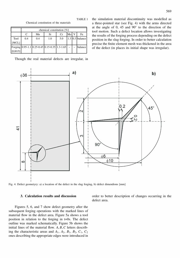
Material discontinuity not only does cause a localchange in strain distribution but also changes plasticstrain in the whole forging volume. Figure 10 and 11present plastic strain distribution in a section of the forg-
573
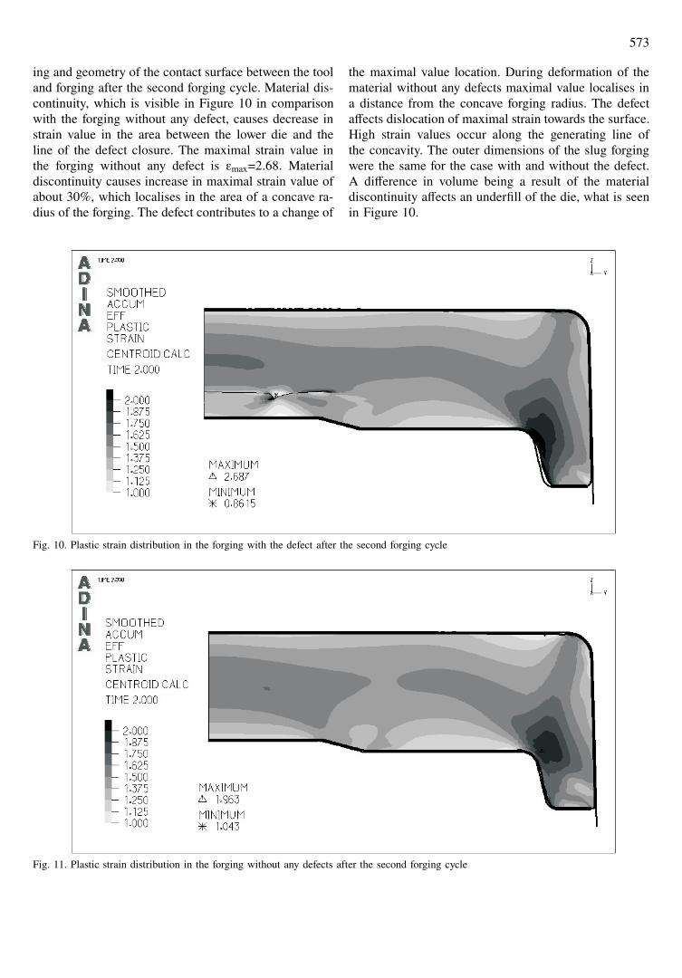
ing and geometry of the contact surface between the tooland forging after the second forging cycle. Material dis-continuity, which is visible in Figure 10 in comparisonwith the forging without any defect, causes decrease instrain value in the area between the lower die and theline of the defect closure. The maximal strain value inthe forging without any defect is εmax=2.68. Materialdiscontinuity causes increase in maximal strain value ofabout 30%, which localises in the area of a concave ra-dius of the forging. The defect contributes to a change of
the maximal value location. During deformation of thematerial without any defects maximal value localises ina distance from the concave forging radius. The defectaffects dislocation of maximal strain towards the surface.High strain values occur along the generating line ofthe concavity. The outer dimensions of the slug forgingwere the same for the case with and without the defect.A difference in volume being a result of the materialdiscontinuity affects an underfill of the die, what is seenin Figure 10.
Fig. 10. Plastic strain distribution in the forging with the defect after the second forging cycle
Fig. 11. Plastic strain distribution in the forging without any defects after the second forging cycle

574
4. Conclusions
The calculations allow assessing the effects of ma-terial discontinuity in the forging. According to the nu-merical simulation analysis of the die forging process itis possible to draw the following conclusions:1. Material discontinuity depending on deformation
conditions can close and open again during the forg-ing process. The defect surfaces move relatively toeach other during the whole forging cycle. Depend-ing on the initial defect geometry there is a changein length of surfaces, which create the defect. In theanalysed case the horizontal defects lengthen whilevertical ones shorten.
2. In the defect area a relative extreme of plastic strainappears. High strain values in the zone of sharp de-fect edge can be extremely dangerous. It can lead tothe further development of the defect.
3. Material discontinuity affects changes in strain statein the forging. It results in decrease of the strainvalue in the zone under the line of defect closurerespecting the forging with no defect and increase ofmaximal strain values.
4. Numerical simulations allow exploring and analysingtechnological processes. The proper technology al-lows obtaining the products of better quality.
Acknowledgements
Financial support of Structural Funds in the Operational Pro-gramme – Innovative Economy (IE OP) financed from the EuropeanRegional Development Fund – Project No POIG.0101.02-00-015/08is gratefully acknowledged.
REFERENCES
[1] P. W a s i u n y k, Kucie matrycowe. Warszawa: WNT,1987.
[2] Z. K r z e k o t o w s k i, Technologia kucia swobod-nego i półswobodnego. Poland Katowice: Wydawnictwo„ŚLĄSK”, 1964.
[3] AV. K u t y s k i n, Veroatnostnaa ocenka vozniknoveniadefektov pri obrezke obloa i probivke peremycki osesim-metricnych pokovok. Kuzn.-stampov. Proiz. 43, 9 (2001).
[4] J. A d a m u s, M. G i e r z y ń s k a - D o l n a, P. L a c -k i, Kompleksowe sterowanie jakością odkuwek ma-trycowych. Obróbka Plastyczna, 2001. [5] Ohasi T, Moto-mura M. Expert system of cold forging defects using riskanalysis tree network with fuzzy language. J. Mat. Proc.Technol. 107, 1-3 (2000).
[5] R. B a l e n d r a, Y. Q i n, Identification and classificationof flow-dependent defects in the injection forging of solidbillet. J. Mat. Proc. Technol. 106, 1-3 (2000).
[6] J. R a d e c k i, E. Ł a b u d a, Symulacja zmian obję-tości nieciągłości materiałowych w czasie odkształceniaplastycznego. Materiały VI Konferencji pt. ZastosowanieKomputerów w Zakładach Przetwórstwa Metali. KomPlas-Tech’99. Poland-Szczyrk, 1999.
[7] R. S z y n d l e r, J. S i ń c z a k Wpływ konstrukcji ma-tryc na dokładność wykonania odkuwek. Materiały kon-ferencji QUALITY 2001 Inżynieria Jakości w TechnikachWytwarzania. Częstochowa, 2001.
[8] J. S i ń c z a k, A. Ł u k a s z e k, Obciążenie narzędziprzy kuciu wielokrotnym pierścieni łożysk tocznych.Obróbka Plastyczna Metali 12, 3 (2001).
Received: 20 May 2009.