Numerical analysis of the early age behavior of concrete structures with a hydration based...
17
Numerical analysis of the early age behavior of concrete structures with a hydration based microplane model Yun Lee a, * , Jin-Keun Kim b,1 a Department of Architecture, College of Engineering, Ewha Womans University, 11-1, Daehyun-dong, Seodaemun-gu, Seoul 120-750, South Korea b Department of Civil and Environmental Engineering, Korea Advanced Institute of Science and Technology (KAIST), 373-1, Guseong-dong, Yuseong-gu, Daejeon 305-701, South Korea article info Article history: Received 12 July 2008 Accepted 15 May 2009 Available online 3 June 2009 Keywords: Early age Cracking Hydration Microplane model Finite element analysis Concrete structure abstract To simulate the early age behavior of concrete structures composed of young concrete, a finite element analysis (FEA) was implemented with the hydration based microplane model. Structural behaviors were investigated with concrete age for a massive concrete wall and slab. From FEA, it was found that surface cracking at early age occurred via different crack driving mechanisms. In the case of combined hydration heat and shrinkage, later surface cracking was produced by differential drying shrinkage. A numerical analysis performed with the hydration based microplane model successfully simulated the typical crack- ing patterns due to edge restraint in the concrete slab. Ó 2009 Elsevier Ltd. All rights reserved. 1. Introduction Fundamentally, concrete structures show various behaviors after being placed at construction sites due to the stress inducing mechanisms of hydration heat, autogenous shrinkage, and drying shrinkage. For the verification and prediction of concrete behavior, numerical schemes such as the finite element method (FEM) and the finite difference method (FDM) are considered powerful tools. To date, numerous efforts have been undertaken to develop constitutive material models for the description of the mechanical behavior of early age concrete. Beside compressive stress–strain material models as reported in [1–3], tensile softening models describing cracking behavior [4–6] have been applied to numerical simulations in hardening concrete elements [7–9]. Aforemen- tioned approaches to early age concrete are basically drawn from experiments and considerations of uniaxial stress state. To simu- late a realistic three-dimensional finite element analysis of early age concrete, Kim and Lee [10] developed a hydration based micro- plane model that addresses not only multiaxial structural behavior but also the early age behavior for concrete. In this paper, a finite element analysis implemented with the hydration based microplane model is performed to simulate the early age behavior of a concrete structure. As the outcome of finite element analysis, the variations of stress and deformation with time and cracking behaviors are investigated for massive concrete structures. In Section 2, the numerical considerations for the treatment of the early age behavior are introduced. The methodology of the numerical analysis and the implemented constitutive material model, as well as some computational aspects of the FE analysis with the material model, are introduced briefly. In Section 3, a numerical analysis of a massive concrete wall is pre- sented. To estimate the effects of various stress inducing mechanisms on the early age behavior of concrete, the numerical analysis is per- formed for three types of crack driving forces (i.e. hydration heat; coupled hydration heat and autogenous shrinkage; and coupled hydration heat, autogenous shrinkage, and drying shrinkage). In Section 4, a numerical analysis of a massive concrete slab is presented. To estimate the effects of stress inducing mechanisms and reinforcement, the numerical analysis is performed for two types of concrete slab, i.e. a plain concrete slab and a reinforced concrete slab. 2. Numerical considerations for the early age behavior 2.1. Constitutive material model: hydration based microplane model For a nonlinear analysis of concrete, various constitutive models such as the plasticity-based model, damage-based model, and microplane model have thus far been developed. Among these models, the plasticity-based model has been widely used to de- scribe the nonlinear behavior of concrete. Differently from the plasticity-based model formulated in terms of stress and strain tensors and their invariants, the microplane model is formulated 0045-7949/$ - see front matter Ó 2009 Elsevier Ltd. All rights reserved. doi:10.1016/j.compstruc.2009.05.008 * Corresponding author. Tel.: +82 2 3277 6707; fax: +82 2 3277 2396. E-mail addresses: [email protected] (Y. Lee), [email protected] (J.-K. Kim). 1 Tel.: +82 42 869 3614; fax: +82 42 869 3688. Computers and Structures 87 (2009) 1085–1101 Contents lists available at ScienceDirect Computers and Structures journal homepage: www.elsevier.com/locate/compstruc
Transcript of Numerical analysis of the early age behavior of concrete structures with a hydration based...

Computers and Structures 87 (2009) 1085–1101
Contents lists available at ScienceDirect
Computers and Structures
journal homepage: www.elsevier .com/locate /compstruc
Numerical analysis of the early age behavior of concrete structureswith a hydration based microplane model
Yun Lee a,*, Jin-Keun Kim b,1
a Department of Architecture, College of Engineering, Ewha Womans University, 11-1, Daehyun-dong, Seodaemun-gu, Seoul 120-750, South Koreab Department of Civil and Environmental Engineering, Korea Advanced Institute of Science and Technology (KAIST), 373-1, Guseong-dong, Yuseong-gu, Daejeon 305-701, South Korea
a r t i c l e i n f o
Article history:Received 12 July 2008Accepted 15 May 2009Available online 3 June 2009
Keywords:Early ageCrackingHydrationMicroplane modelFinite element analysisConcrete structure
0045-7949/$ - see front matter � 2009 Elsevier Ltd. Adoi:10.1016/j.compstruc.2009.05.008
* Corresponding author. Tel.: +82 2 3277 6707; faxE-mail addresses: [email protected] (Y. Lee), kimji
1 Tel.: +82 42 869 3614; fax: +82 42 869 3688.
a b s t r a c t
To simulate the early age behavior of concrete structures composed of young concrete, a finite elementanalysis (FEA) was implemented with the hydration based microplane model. Structural behaviors wereinvestigated with concrete age for a massive concrete wall and slab. From FEA, it was found that surfacecracking at early age occurred via different crack driving mechanisms. In the case of combined hydrationheat and shrinkage, later surface cracking was produced by differential drying shrinkage. A numericalanalysis performed with the hydration based microplane model successfully simulated the typical crack-ing patterns due to edge restraint in the concrete slab.
� 2009 Elsevier Ltd. All rights reserved.
1. Introduction In Section 2, the numerical considerations for the treatment of
Fundamentally, concrete structures show various behaviorsafter being placed at construction sites due to the stress inducingmechanisms of hydration heat, autogenous shrinkage, and dryingshrinkage. For the verification and prediction of concrete behavior,numerical schemes such as the finite element method (FEM) andthe finite difference method (FDM) are considered powerful tools.
To date, numerous efforts have been undertaken to developconstitutive material models for the description of the mechanicalbehavior of early age concrete. Beside compressive stress–strainmaterial models as reported in [1–3], tensile softening modelsdescribing cracking behavior [4–6] have been applied to numericalsimulations in hardening concrete elements [7–9]. Aforemen-tioned approaches to early age concrete are basically drawn fromexperiments and considerations of uniaxial stress state. To simu-late a realistic three-dimensional finite element analysis of earlyage concrete, Kim and Lee [10] developed a hydration based micro-plane model that addresses not only multiaxial structural behaviorbut also the early age behavior for concrete.
In this paper, a finite element analysis implemented with thehydration based microplane model is performed to simulate the earlyage behavior of a concrete structure. As the outcome of finite elementanalysis, the variations of stress and deformation with time andcracking behaviors are investigated for massive concrete structures.
ll rights reserved.
: +82 2 3277 [email protected] (J.-K. Kim).
the early age behavior are introduced. The methodology of thenumerical analysis and the implemented constitutive materialmodel, as well as some computational aspects of the FE analysiswith the material model, are introduced briefly.
In Section 3, a numerical analysis of a massive concrete wall is pre-sented. To estimate the effects of various stress inducing mechanismson the early age behavior of concrete, the numerical analysis is per-formed for three types of crack driving forces (i.e. hydration heat;coupled hydration heat and autogenous shrinkage; and coupledhydration heat, autogenous shrinkage, and drying shrinkage).
In Section 4, a numerical analysis of a massive concrete slab ispresented. To estimate the effects of stress inducing mechanismsand reinforcement, the numerical analysis is performed for twotypes of concrete slab, i.e. a plain concrete slab and a reinforcedconcrete slab.
2. Numerical considerations for the early age behavior
2.1. Constitutive material model: hydration based microplane model
For a nonlinear analysis of concrete, various constitutive modelssuch as the plasticity-based model, damage-based model, andmicroplane model have thus far been developed. Among thesemodels, the plasticity-based model has been widely used to de-scribe the nonlinear behavior of concrete. Differently from theplasticity-based model formulated in terms of stress and straintensors and their invariants, the microplane model is formulated

1086 Y. Lee, J.-K. Kim / Computers and Structures 87 (2009) 1085–1101
in terms of vectors rather than tensors. Gradual progress has beenmade through a series of incrementally improved microplane mod-els, named Ml, M2, M3, and M4, for concrete [11–16]. Recently, themicroplane model was improved to capture the complex inelasticbehaviors of concrete very effectively.
Although the microplane model has been employed to describethe complex behaviors of concrete under various stress states,these efforts have been limited to hardened concrete. For this rea-son, the microplane model in its original form was incapable ofdescribing the early age behavior of young concrete. In order to ad-dress this shortcoming, a microplane model based on the hydrationconcept of concrete was developed by Kim and Lee [10].
In the original microplane model M4 [15], compressive nonlin-ear behavior such as axial crushing with lateral expansion could bedescribed by the deviatoric boundary. To describe the inelasticnonlinear behavior of early age concrete before hardening, a non-linear function f ðeDÞf(eD) is multiplied by the existing negativedeviatoric boundary in M4, as given in Eq. (1) [10].
rb�D ¼ �
EDk1c8
1þ h�eD�k1c8c9ik1c7
� �2 f ðeDÞ
f ðeDÞ ¼ ð1� aÞ½1� eð�beD=k1Þ� þ a ð1Þ
In contrast to the original deviatoric boundary in M4, two additionalparameters, a and b, are added to define the function f ðeDÞ in themodified boundary. In the function f ðeDÞ, a represents the degreeof consistency of the developed boundary with the original bound-ary, and b denotes the degree of nonlinearity of the developedboundary curve [10].
On the other hand, the tensile softening nonlinear behavior ischaracterized by a normal boundary, as given in Eq. (2) in micro-plane model M4 [15].
rbþN ¼ Ek1c1 exp � heN � k1c1c2i
k1c3 þ h�c4rV=EV i
� �ð2Þ
In this equation, two parameters, c2 and c3, control the roundness ofthe peak and the steepness of the post-peak descent under uniaxialtension, respectively.
In the original microplane model M4, the parameters ci are re-garded as fixed values. Within the framework of the hydrationbased microplane model, the two parameters c2 and c3 in Eq. (2),which characterize tensile softening in the normal boundary, werecalibrated with the degree of hydration of aging concrete [10].
A hydration based formulation for parameters constituting Eqs.(1) and (2) can be established with Eq. (3), as follows [10]:
PðnÞPn¼1:0
¼ n� n0
1� n0
� �k
ð3Þ
where P(n) is the parameter varying with age and degree of hydra-tion, Pn = 1.0 is the value at n = 1.0, and k is a model coefficient.
A hydration based microplane model that incorporates Eq. (3)with the existing microplane model M4 [15] can describe the earlyage structural behaviors as the degree of hydration evolves withincreasing concrete age.
2.2. Methodology of numerical analysis
A numerical analysis for early age behavior is carried out usingthe finite element code CONSA/HS, a 3D finite element analysisprogram developed at Korea Advanced Institute of Science andTechnology (KAIST) for hydration heat transfer, moisture diffusion,and corresponding stress analysis. The employed code is capable ofsimulating stress inducing mechanisms such as hydration heat,autogenous shrinkage, and differential drying shrinkage. Althoughthe original code was developed based on the Hook’s law of elastic-
ity, the hydration based microplane model reported by Kim andLee [10] is implemented as a concrete constitutive law for thisstudy.
To calculate stresses due to hydration heat, differential dryingshrinkage, autogenous shrinkage, and creep, the minimum poten-tial energy principle is introduced. In an elastic body, potential en-ergy can be expressed as given by the following equation:
Pp ¼ U �Wp ð4Þ
where Pp is the potential energy, U is the strain energy, and Wp isthe energy due to external applied forces.
In Eq. (4), the strain energy and the energy due to external ap-plied forces are as follows:
U ¼Z
V
Z e
0frgde
� �dV ð5Þ
Wp ¼ fFgfdg ð6Þ
where {r} is the internal stress, e is the strain, {F} is the external ap-plied force, and {d} is the displacement.
Considering only mechanical strain, which can be calculated bysubtracting the strains produced by temperature, shrinkage, andcreep from total strain, the stress can be obtained by Eq. (7).
frg ¼ ½D�ðfeg � feCg � feTg � fedshg � feashgÞ ð7Þ
where [D] is the stiffness matrix of the material, {eC} is the creepstrain, {eT} is the thermal strain, {edsh} is the differential dryingshrinkage strain, and {eash} is the autogenous shrinkage strain.
Inserting Eq. (7) into Eq. (5), Eq. (8) is obtained.
U ¼Z
V
Z e
0½D�ðfeg � feCg � feTg � fedshg � feashgÞde
� �dV
¼Z
V
12½D�feg2
� �dV �
ZV½½D�ðfeCg þ feTg þ fedshg þ feashg�dV
ð8Þ
For all nodes of each element, the displacement–strain relationshipis given as
e ¼ ½B�fdg ¼ fex; ey; ez; cxy; cyz; czxgT ð9Þ
where [B] is the displacement–strain matrix, ex, ey, ez, cxy, cyz, czx arestrains in each direction, and T denotes the transpose of the matrix.
Inserting Eqs. (6), (8), and (9) into Eq. (4) and minimizing Pp, Eq.(10) can be obtained.
@Pp
@fdg ¼Z
V½B�T ½D�½B�dV
� fdg �
ZV½B�T ½D�½feCg þ feTg
þ fedshg þ feashg�dV � fFg ¼ 0 ð10Þ
Expressing Eq. (10) in a matrix form, Eq. (11) is finally obtained.
½K�fdg ¼ fFg þ fFgC þ fFgT þ fFgdsh þ fFgash ð11Þ
In Eq. (11), [K], {F}C, {F}T, {F}dsh, and {F}ash are expressed by the fol-lowing equations, respectively.
½K� ¼Z
V½B�T ½D�½B�dV ð12Þ
fFgC ¼Z
V½B�T ½D�feCgdV ð13Þ
fFgT ¼Z
V½B�T ½D�feTgdV ð14Þ
fFgdsh ¼Z
V½B�T ½D�fedshgdV ð15Þ
fFgash ¼Z
V½B�T ½D�feashgdV ð16Þ
The finite element analysis with a microplane model is, numeri-cally, extremely demanding. The computation of the stress tensor
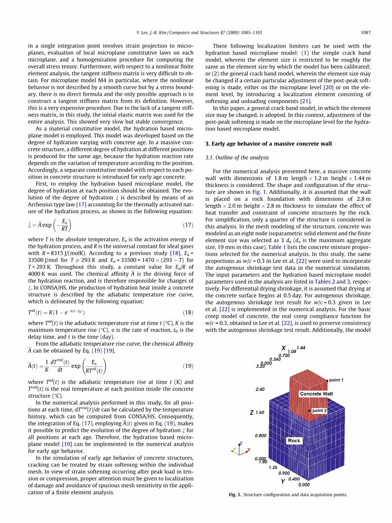
Fig. 1. Structure configuration and data acquisition points.
Y. Lee, J.-K. Kim / Computers and Structures 87 (2009) 1085–1101 1087
in a single integration point involves strain projection to micro-planes, evaluation of local microplane constitutive laws on eachmicroplane, and a homogenization procedure for computing theoverall stress tensor. Furthermore, with respect to a nonlinear finiteelement analysis, the tangent stiffness matrix is very difficult to ob-tain. For microplane model M4 in particular, where the nonlinearbehavior is not described by a smooth curve but by a stress bound-ary, there is no direct formula and the only possible approach is toconstruct a tangent stiffness matrix from its definition. However,this is a very expensive procedure. Due to the lack of a tangent stiff-ness matrix, in this study, the initial elastic matrix was used for theentire analysis. This showed very slow but stable convergence.
As a material constitutive model, the hydration based micro-plane model is employed. This model was developed based on thedegree of hydration varying with concrete age. In a massive con-crete structure, a different degree of hydration at different positionsis produced for the same age, because the hydration reaction ratedepends on the variation of temperature according to the position.Accordingly, a separate constitutive model with respect to each po-sition in concrete structure is introduced for early age concrete.
First, to employ the hydration based microplane model, thedegree of hydration at each position should be obtained. The evo-lution of the degree of hydration n is described by means of anArrhenius type law [17] accounting for the thermally activated nat-ure of the hydration process, as shown in the following equation:
_n ¼ A exp � Ea
RT
� �ð17Þ
where T is the absolute temperature, Ea is the activation energy ofthe hydration process, and R is the universal constant for ideal gaseswith R = 8315 J/(molK). According to a previous study [18], Ea =33500 J/mol for T P 293 K and Ea = 33500 + 1470 � (293 � T) forT < 293 K. Throughout this study, a constant value for Ea/R of4000 K was used. The chemical affinity A is the driving force ofthe hydration reaction, and is therefore responsible for changes ofn. In CONSA/HS, the production of hydration heat inside a concretestructure is described by the adiabatic temperature rise curve,which is delineated by the following equation:
TadðtÞ ¼ Kð1� e�aðt�t0ÞÞ ð18Þ
where Tad(t) is the adiabatic temperature rise at time t (�C), K is themaximum temperature rise (�C), a is the rate of reaction, t0 is thedelay time, and t is the time (day).
From the adiabatic temperature rise curve, the chemical affinityA can be obtained by Eq. (19) [19].
AðtÞ ¼ 1K
dTrealðtÞdt
expEa
RTadðtÞ
!ð19Þ
where Tad(t) is the adiabatic temperature rise at time t (K) andTreal(t) is the real temperature at each position inside the concretestructure (�C).
In the numerical analysis performed in this study, for all posi-tions at each time, dTreal(t)/dt can be calculated by the temperaturehistory, which can be computed from CONSA/HS. Consequently,the integration of Eq. (17), employing AðtÞ given in Eq. (19), makesit possible to predict the evolution of the degree of hydration n forall positions at each age. Therefore, the hydration based micro-plane model [10] can be implemented in the numerical analysisfor early age behavior.
In the simulation of early age behavior of concrete structures,cracking can be treated by strain softening within the individualmesh. In view of strain softening occurring after peak load in ten-sion or compression, proper attention must be given to localizationof damage and avoidance of spurious mesh sensitivity in the appli-cation of a finite element analysis.
There following localization limiters can be used with thehydration based microplane model: (1) the simple crack bandmodel, wherein the element size is restricted to be roughly thesame as the element size by which the model has been calibrated;or (2) the general crack band model, wherein the element size maybe changed if a certain particular adjustment of the post-peak soft-ening is made, either on the microplane level [20] or on the ele-ment level, by introducing a localization element consisting ofsoftening and unloading components [21].
In this paper, a general crack band model, in which the elementsize may be changed, is adopted. In this context, adjustment of thepost-peak softening is made on the microplane level for the hydra-tion based microplane model.
3. Early age behavior of a massive concrete wall
3.1. Outline of the analysis
For the numerical analysis presented here, a massive concretewall with dimensions of 1.8 m length � 1.2 m height � 1.44 mthickness is considered. The shape and configuration of the struc-ture are shown in Fig. 1. Additionally, it is assumed that the wallis placed on a rock foundation with dimensions of 2.8 mlength � 2.0 m height � 2.8 m thickness to simulate the effect ofheat transfer and constraint of concrete structures by the rock.For simplification, only a quarter of the structure is considered inthis analysis. In the mesh modeling of the structure, concrete wasmodeled as an eight node isoparametric solid element and the finiteelement size was selected as 3 da (da is the maximum aggregatesize, 19 mm in this case). Table 1 lists the concrete mixture propor-tions selected for the numerical analysis. In this study, the sameproportions as w/c = 0.3 in Lee et al. [22] were used to incorporatethe autogenous shrinkage test data in the numerical simulation.The input parameters and the hydration based microplane modelparameters used in the analysis are listed in Tables 2 and 3, respec-tively. For differential drying shrinkage, it is assumed that drying atthe concrete surface begins at 0.5 day. For autogenous shrinkage,the autogenous shrinkage test result for w/c = 0.3 given in Leeet al. [22] is implemented in the numerical analysis. For the basiccreep model of concrete, the real creep compliance function forw/c = 0.3, obtained in Lee et al. [22], is used to preserve consistencywith the autogenous shrinkage test result. Additionally, the model

Table 1Concrete mixture proportions [22].
w/c s/a Unit weight (kg/m3) Adb (%)
W C S Ga
0.3 0.37 175 583 591 999 1.0
a Maximum aggregate size of 19 mm.b Superplasticizer (high-range water-reducing admixture), ratio of cement
weight.
Table 3Parameters for the hydration based microplane model [10] (related to Eq. (3)).
Parameters Pn = 1.0 Model coefficient (k)
E (MPa) 53,000 1.140a 1.0 1.189b 0.00763 0.434c2 2.76 �0.569c3 4.0 �0.577
Fig. 2. Temperature distributions at 1 day (elastic analysis).
1088 Y. Lee, J.-K. Kim / Computers and Structures 87 (2009) 1085–1101
parameters in Kim and Lee [10] are implemented as the microplanemodel parameters in the finite element analysis.
The analysis cases for hydration heat, hydration heat and autog-enous shrinkage, and hydration heat, autogenous, and differentialdrying shrinkage are denoted as HH, HA, and HAD, respectively.For comparison of the stress history among the stress inducingmechanisms, such as HH, HA, and HAD, two representative outputpoints are selected as shown in Fig. 1.
3.2. Stress evolution in a massive concrete wall
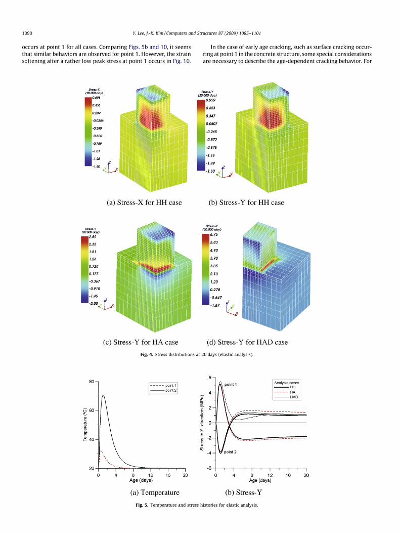
Figs. 2–5 show the analysis results for the elastic analysis con-sidering three stress inducing mechanisms at early ages, i.e. HH,HA, and HAD. For the temperature distribution, as shown inFig. 2, the maximum temperature at 1 day in the center of the con-crete wall is approximately 74.5 �C. This rapid temperature rise iscaused by a high hydration rate due to high cement content. Com-paring the two cases presented in Fig. 3a and b, it is seen that ten-sile stress-Y at the surface of the central section is higher thantensile stress-X. This is because the effect of thermal expansionin the Y-direction is larger than that in the X-direction due to thedifference of corresponding dimensions. Hence, if cracking occursat an early age, tensile stress-Y at the surface may govern the earlyage cracking behavior in the concrete wall. Tensile stress producedat the concrete surface at the early age stage is due to a rapid tem-perature rise inside the concrete structure and the correspondinginternal restraint effect. In contrast with tensile stress, compressivestress is developed due to the combined internal and external re-straint effects. In general, high cement content produces not onlya rapid temperature rise, but also fast strength evolution and cor-responding high material strength. These combined mechanismsinduce tensile stress at early ages, and complicate prediction ofthe early age cracking behavior. This is further exacerbated as addi-tional stress evolving mechanisms, such as autogenous and dryingshrinkage, are produced.
In Fig. 3c and d, stress distributions due to HA and HAD are de-picted. For the HA case, it is seen that tensile stress at the surfaceand compressive stress at the center are small in magnitude rela-tive to the HH case. The observation of tensile stress that is lowerthan that of the HH case is somewhat surprising, since autogenousshrinkage causes tensile stress in an ordinary concrete structure.
Table 2Input data used in numerical analysis.
Parameters
Adiabatic temperature rise (Type I) Maximum temperature riRate of reaction
Thermal properties Thermal conductivity (kcSpecific heat (kcal/kg �C)Heat transfer coefficient (Unit density (kgf/m3)Thermal expansion coeffi
Environmental conditions Temperature (�C)Humidity (%)
Smaller tensile stress in magnitude for the HA case is due to thefact that early age tensile stress at the surface is produced by inter-nal restraint instead of external restraint. Autogenous shrinkage isalways negative and occurs in every portion of a concrete struc-ture, and therefore it influences inner portions as well as the con-crete surface. The negative autogenous deformation of the HA caseoffsets positive thermal expansion inside the concrete structure,thus resulting in smaller compressive stress compared to the HHcase. Hence, the internal restraint effect of the HA case due tothe smaller compressive stress is decreased in comparison withthe HH case. Consequently, the reduced internal restraint effectcauses low tensile and compressive stress. Thus, it is seen that atthe early age stage, the compressive stress inside the massive con-crete structure plays an important role in the evolution of tensilestress at the concrete surface.
Contrary to the HA case, the tensile stress at the surface for theHAD case is larger than that of the other two cases while the com-pressive stress is small in magnitude in comparison with the HHcase. This behavior is due to the differential drying shrinkage,which occurs at the concrete surface. In contrast with autogenousshrinkage, which takes place throughout the concrete structure,
Concrete Rock
se (�C) 71.6 –1.989 –
al/m h �C) 2.3 2.10.27 0.18
kcal/m2 h �C) 12 122320 2200
cient (/�C) 10 � 10�6 7.5
20 2060 100
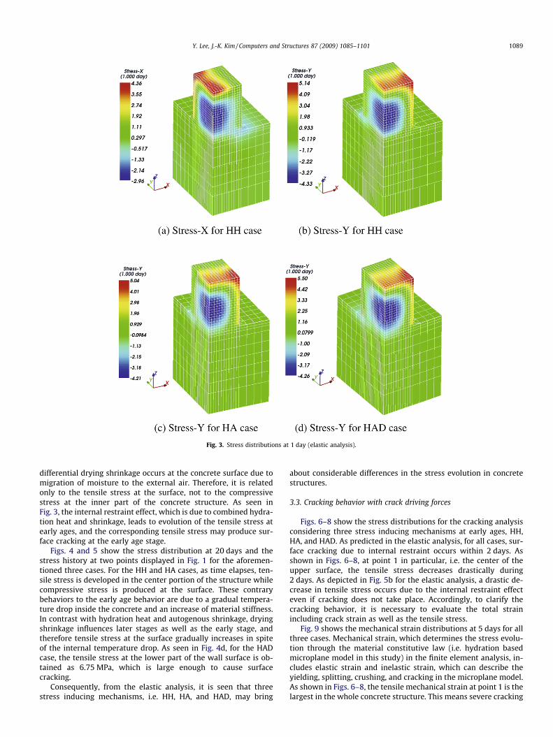
Fig. 3. Stress distributions at 1 day (elastic analysis).
Y. Lee, J.-K. Kim / Computers and Structures 87 (2009) 1085–1101 1089
differential drying shrinkage occurs at the concrete surface due tomigration of moisture to the external air. Therefore, it is relatedonly to the tensile stress at the surface, not to the compressivestress at the inner part of the concrete structure. As seen inFig. 3, the internal restraint effect, which is due to combined hydra-tion heat and shrinkage, leads to evolution of the tensile stress atearly ages, and the corresponding tensile stress may produce sur-face cracking at the early age stage.
Figs. 4 and 5 show the stress distribution at 20 days and thestress history at two points displayed in Fig. 1 for the aforemen-tioned three cases. For the HH and HA cases, as time elapses, ten-sile stress is developed in the center portion of the structure whilecompressive stress is produced at the surface. These contrarybehaviors to the early age behavior are due to a gradual tempera-ture drop inside the concrete and an increase of material stiffness.In contrast with hydration heat and autogenous shrinkage, dryingshrinkage influences later stages as well as the early stage, andtherefore tensile stress at the surface gradually increases in spiteof the internal temperature drop. As seen in Fig. 4d, for the HADcase, the tensile stress at the lower part of the wall surface is ob-tained as 6.75 MPa, which is large enough to cause surfacecracking.
Consequently, from the elastic analysis, it is seen that threestress inducing mechanisms, i.e. HH, HA, and HAD, may bring
about considerable differences in the stress evolution in concretestructures.
3.3. Cracking behavior with crack driving forces
Figs. 6–8 show the stress distributions for the cracking analysisconsidering three stress inducing mechanisms at early ages, HH,HA, and HAD. As predicted in the elastic analysis, for all cases, sur-face cracking due to internal restraint occurs within 2 days. Asshown in Figs. 6–8, at point 1 in particular, i.e. the center of theupper surface, the tensile stress decreases drastically during2 days. As depicted in Fig. 5b for the elastic analysis, a drastic de-crease in tensile stress occurs due to the internal restraint effecteven if cracking does not take place. Accordingly, to clarify thecracking behavior, it is necessary to evaluate the total strainincluding crack strain as well as the tensile stress.
Fig. 9 shows the mechanical strain distributions at 5 days for allthree cases. Mechanical strain, which determines the stress evolu-tion through the material constitutive law (i.e. hydration basedmicroplane model in this study) in the finite element analysis, in-cludes elastic strain and inelastic strain, which can describe theyielding, splitting, crushing, and cracking in the microplane model.As shown in Figs. 6–8, the tensile mechanical strain at point 1 is thelargest in the whole concrete structure. This means severe cracking
1090 Y. Lee, J.-K. Kim / Computers and Structures 87 (2009) 1085–1101
occurs at point 1 for all cases. Comparing Figs. 5b and 10, it seemsthat similar behaviors are observed for point 1. However, the strainsoftening after a rather low peak stress at point 1 occurs in Fig. 10.
Fig. 4. Stress distributions at
Fig. 5. Temperature and stress h
In the case of early age cracking, such as surface cracking occur-ring at point 1 in the concrete structure, some special considerationsare necessary to describe the age-dependent cracking behavior. For
20 days (elastic analysis).
istories for elastic analysis.

Fig. 6. Stress-Y distributions for HH case (cracking analysis).
Fig. 7. Stress-Y distributions for HA case (cracking analysis).
Fig. 8. Stress-Y distributions for HAD case (cracking analysis).
Y. Lee, J.-K. Kim / Computers and Structures 87 (2009) 1085–1101 1091

1092 Y. Lee, J.-K. Kim / Computers and Structures 87 (2009) 1085–1101
the early age stage, where the material stiffness and strength varyrapidly, cracking behavior is somewhat different from the hardenedconcrete case. Fig. 11 shows the stress and stress boundary evolu-
Fig. 10. Stress histories for cracking analysis.
Fig. 9. Mechanical (elastic + inelastic) strain d
tion with age increment. In Fig. 11, rN, eN, and rbN denote the normal
stress, normal strain, and normal stress boundary, respectively, inmicroplane model M4 [15]. For hardened concrete, wherein the
Fig. 11. Stress and stress boundary evolution with age increment.
istributions at 5 days (cracking analysis).
Y. Lee, J.-K. Kim / Computers and Structures 87 (2009) 1085–1101 1093
material stiffness and normal boundary are constant, point P on thesoftening region at time t1 moves to point B in the next step, follow-ing the normal boundary rb
Nðt2Þ, which is the same as rbNðt1Þ, with a
normal strain increment DeN. This reflects typical tensile softeningbehavior for ordinary concrete. In contrast, at the early age stage,rb
Nðt2Þ is different from rbNðt1Þ and the stiffness E(t2) is larger than
E(t1). Accordingly, point P at time t1 moves not to point B but to pointA in the next step, following the normal boundary rb
Nðt2Þ. Conse-quently, for early age concrete, there exists some pre-peak nonlin-earity, which is insignificant for hardened concrete, in the overalltensile stress–strain relationships computed from the microplanemodel. This feature diminishes as concrete hardening progresses.
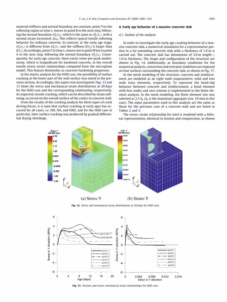
In the elastic analysis for the HAD case, the possibility of surfacecracking at the lower part of the wall surface was noted in the pre-vious section. Accordingly, this aspect was investigated. Figs. 12 and13 show the stress and mechanical strain distributions at 20 daysfor the HAD case and the corresponding relationship, respectively.As expected, tensile cracking, which can be described by strain soft-ening, occurred on the overall surface of the center in concrete wall.
From the results of the cracking analysis for three types of crackdriving forces, it is seen that surface cracking at early ages has oc-curred for all cases, i.e. HH, HA, and HAD, and for the HAD case inparticular, later surface cracking was produced by gradual differen-tial drying shrinkage.
Fig. 13. Stresses and stress–mechanical
Fig. 12. Stress and mechanical strain dis
4. Early age behavior of a massive concrete slab
4.1. Outline of the analysis
In order to investigate the early age cracking behavior of a mas-sive concrete slab, a numerical simulation for a representative por-tion in a far-extending concrete slab with a thickness of 1.0 m iscarried out. The concrete slab has dimensions of 3.0 m length �1.0 m thickness. The shape and configuration of the structure areshown in Fig. 14. Additionally, as boundary conditions for thenumerical analysis, convection and restraint conditions are imposedon four surfaces surrounding the concrete slab, as shown in Fig. 17.
In the mesh modeling of the structure, concrete and reinforce-ment are modeled as an eight node isoparametric solid and twonode truss elements, respectively. To represent the bond-slipbehavior between concrete and reinforcement, a bond elementwith four nodes and zero volume is implemented in the finite ele-ment analysis. In the mesh modeling, the finite element size wasselected as 2.5 da (da is the maximum aggregate size, 19 mm in thiscase). The input parameters used in this analysis are the same asthose for the previous case of a concrete wall and are listed inTables 2 and 3.
The stress–strain relationship for steel is modeled with a bilin-ear representation, identical in tension and compression, as shown
strain relationships for HAD case.
tributions at 20 days for HAD case.

Fig. 14. Mesh modeling for a representative portion of the concrete slab.
Fig. 15. Idealization of steel stress–strain behavior.
Fig. 16. Implemented bond stress-slip curve [23].
Fig. 17. Boundary conditions of numerical analysis.
Table 4Reinforcement information implemented in numerical analysis [23].
Parameters Value
Es (MPa) 200,000fsy (MPa) 400As (mm2) 1963ds (mm) 50Thermal expansion coefficient(/�C) 10 � 10�6
Thermal conductivity(kcal/m h �C) 60
1094 Y. Lee, J.-K. Kim / Computers and Structures 87 (2009) 1085–1101
in Fig. 15. The tangent modulus for the plastic part is taken asEsp = 0.02Es, where Es is the initial modulus. Elastic unloading andreloading is assumed. Additionally, the bond-slip relationship andthe corresponding bond-slip modulus Eb [N/mm3] are modeledby Eq. (20), given below, and are depicted in Fig. 16 [23].
sb ¼ 981wb � 57;361w2b þ 837;383w3
b ð20Þ
Eb ¼dðsbÞdðwbÞ
where sb is the bond stress (MPa) and wb is the slip deformation(mm).
The input parameters for the reinforcement used in the numer-ical analysis are listed in Table 4.
4.2. Cracking behavior due to hydration heat
Figs. 18–22 show the analysis results for plain and reinforcedconcrete slabs. For the temperature distribution, as shown inFig. 18, the maximum temperature at 1 day inside the concreteslab is about 80.1 �C.
In the same manner as for the concrete wall in the previous sec-tion, tensile stress produced in the concrete surface at the early agestage is due to the internal restraint effect. Fig. 19 shows the stressdistributions of the concrete slab at 1.458 days, where the maxi-mum tensile stress at the surface occurs. Maximum tensile stressfor the plain and reinforced concrete slab is 3.86 MPa and3.24 MPa, respectively. Since the reinforcement shares the tensilestress for the reinforced concrete slab, there is a reduction in thetensile stress in the concrete part. However, in contrast with thecase of the concrete wall, tensile surface cracking did not occurin either the plain or the reinforced concrete slab.

Y. Lee, J.-K. Kim / Computers and Structures 87 (2009) 1085–1101 1095
Fig. 20 shows the stress distributions of the plain concrete slabat 20 days from the elastic analysis. As shown in Fig. 20a, tensileand compressive stresses developed at 20 days in the inner portion
Fig. 18. Temperature distrib
Fig. 19. Stress-X distributions of concre
Fig. 20. Stresses of plain concrete slab at 2
Fig. 21. Stresses of plain concrete slab at 2
and outer surface, respectively. This is due to the aforementionedinternal restraint effect and the development of material stiffness.Fig. 20b shows the maximum principal stress distributions of the
utions of concrete slab.
te slab at 1.458 days for HH case.
0 days for HH case (elastic analysis).
0 days for HH case (cracking analysis).

Fig. 22. Stresses of reinforced concrete slab at 20 days for HH case (cracking analysis).
Fig. 23. Stresses and stress–mechanical strain relationships for plain concrete (HH case).
Fig. 24. Stresses and stress–mechanical strain relationships for reinforced concrete (HH case).
1096 Y. Lee, J.-K. Kim / Computers and Structures 87 (2009) 1085–1101

Fig. 25. Steel and bond stresses of reinforcement 1 for HH case.
Fig. 26. Steel and bond stresses of reinforcement 2 for HH case.
Fig. 27. Stress-X distributions of concrete slab at 1.667 days for HA case.
Y. Lee, J.-K. Kim / Computers and Structures 87 (2009) 1085–1101 1097

1098 Y. Lee, J.-K. Kim / Computers and Structures 87 (2009) 1085–1101
plain concrete slab at 20 days from the elastic analysis. Stress con-centration takes place at the lower corner of the concrete slab, andthe corresponding maximum principal tensile stress is 7.03 MPa.This means that it is possible to predict the concrete cracking in
Fig. 28. Stresses of plain concrete
Fig. 29. Stresses of reinforced concr
Fig. 30. Stresses and stress–mechanical strain
the cracking analysis. As shown in Figs. 21 and 22, the maximumprincipal tensile stresses in both cases are 4.67 MPa and4.88 MPa, and thus they are lower than the value (7.03 MPa) ob-tained by the elastic analysis above, while tensile stresses in the
slab at 20 days for HA case.
ete slab at 20 days for HA case.
relationships for plain concrete (HA case).
Y. Lee, J.-K. Kim / Computers and Structures 87 (2009) 1085–1101 1099
X-direction are identical at 3.96 MPa. For these reasons, it is con-cluded that tensile crack occurred at the lower corner of the con-crete slab and the crack direction inclined.
In order to investigate the overall cracking behavior in the con-crete slab, it is necessary to check the crack propagation behavioras well as the crack initiation. Figs. 23 and 24 show the stressesand corresponding stress–strain relations for the plain and rein-forced concrete slab, respectively. As shown in these figures, forthe six positions displayed in the upper figure, it appears that dis-tinct crack propagation does not occur in either case, because ten-sile softening is not shown obviously in the stress–strain relations.
Aside from the cracking behavior, the salient feature of thestress distributions at 20 days depicted in Figs. 21 and 22 is thatthere are little differences in both the stress distributions and thecorresponding stress values between plain concrete and reinforcedconcrete, while there was a prominent reduction of the tensilestress in the reinforced concrete at the early age stage as shown
Fig. 32. Steel and bond stresses of
Fig. 31. Stresses and stress–mechanical strain rel
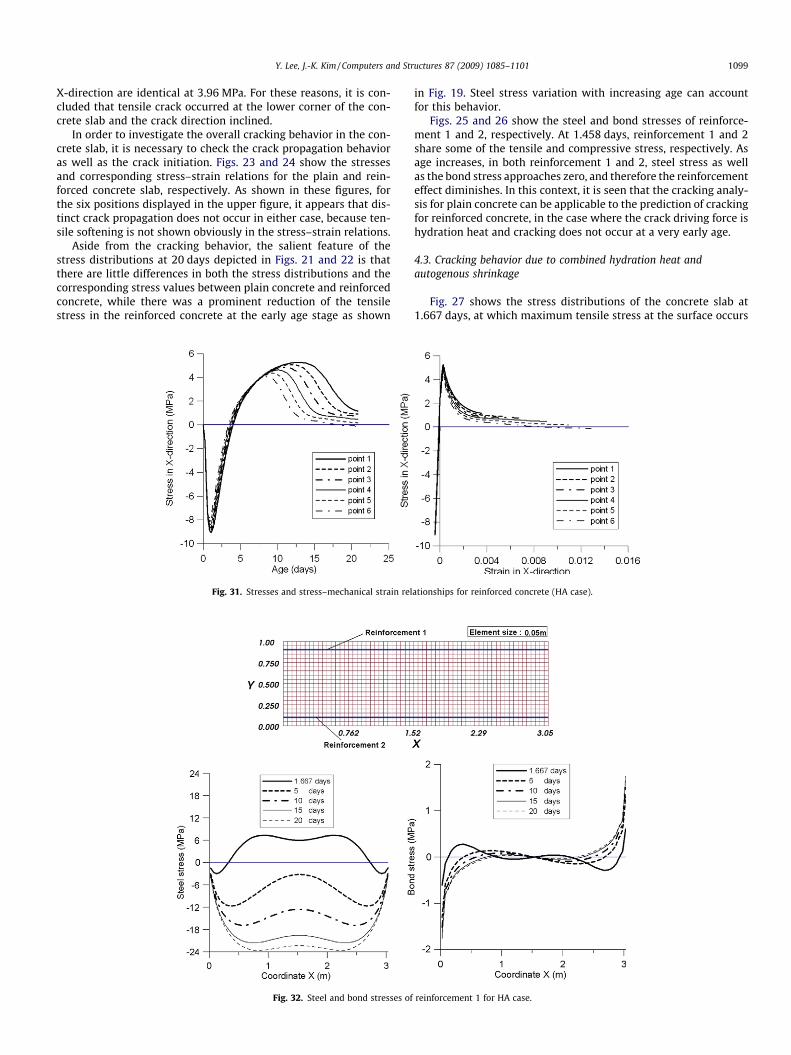
in Fig. 19. Steel stress variation with increasing age can accountfor this behavior.
Figs. 25 and 26 show the steel and bond stresses of reinforce-ment 1 and 2, respectively. At 1.458 days, reinforcement 1 and 2share some of the tensile and compressive stress, respectively. Asage increases, in both reinforcement 1 and 2, steel stress as wellas the bond stress approaches zero, and therefore the reinforcementeffect diminishes. In this context, it is seen that the cracking analy-sis for plain concrete can be applicable to the prediction of crackingfor reinforced concrete, in the case where the crack driving force ishydration heat and cracking does not occur at a very early age.
4.3. Cracking behavior due to combined hydration heat andautogenous shrinkage
Fig. 27 shows the stress distributions of the concrete slab at1.667 days, at which maximum tensile stress at the surface occurs
reinforcement 1 for HA case.
ationships for reinforced concrete (HA case).
1100 Y. Lee, J.-K. Kim / Computers and Structures 87 (2009) 1085–1101
for the HA case. The maximum tensile stress for the plain and rein-forced concrete slab is 3.94 MPa and 3.73 MPa, respectively.Although there is a slight reduction in tensile stress for the rein-forced concrete slab, the difference is smaller than that of the HHcase. The reason for the smaller difference is the autogenousshrinkage, which occurs in concrete only, not in the reinforcement.Accordingly, for the HA case, at the surface, reinforcement acts asan internal restraint source, thus causing tensile stress in additionto the tensile stress induced due to hydration heat.
Figs. 28 and 29 show the stress distributions of the plain andreinforced concrete slab at 20 days, respectively. As seen in Figs.28 and 29, cracking occurs at the bottom of the slab along the con-struction joint between the slab and the lower edge restraint. Inthe same manner as for the HH case, in order to investigate theoverall cracking behavior in the concrete slab, the strain softeningshould be evaluated in the lower edge of concrete slab. Figs. 30 and31 show the stresses and corresponding stress–strain relation forthe plain and reinforced concrete slab, respectively. As shown inthese figures, for six positions along the construction joint, a dropof tensile stress occurs from the exterior surface towards the inte-rior of the slab, whereas in the HH case, cracking was observedonly at the lower corner of the slab. Within the framework of thehydration based microplane model, the degree of hydration atpoint 1 is maximal among all six points, because temperature atpoint 1 has undergone the highest temperature rise history.
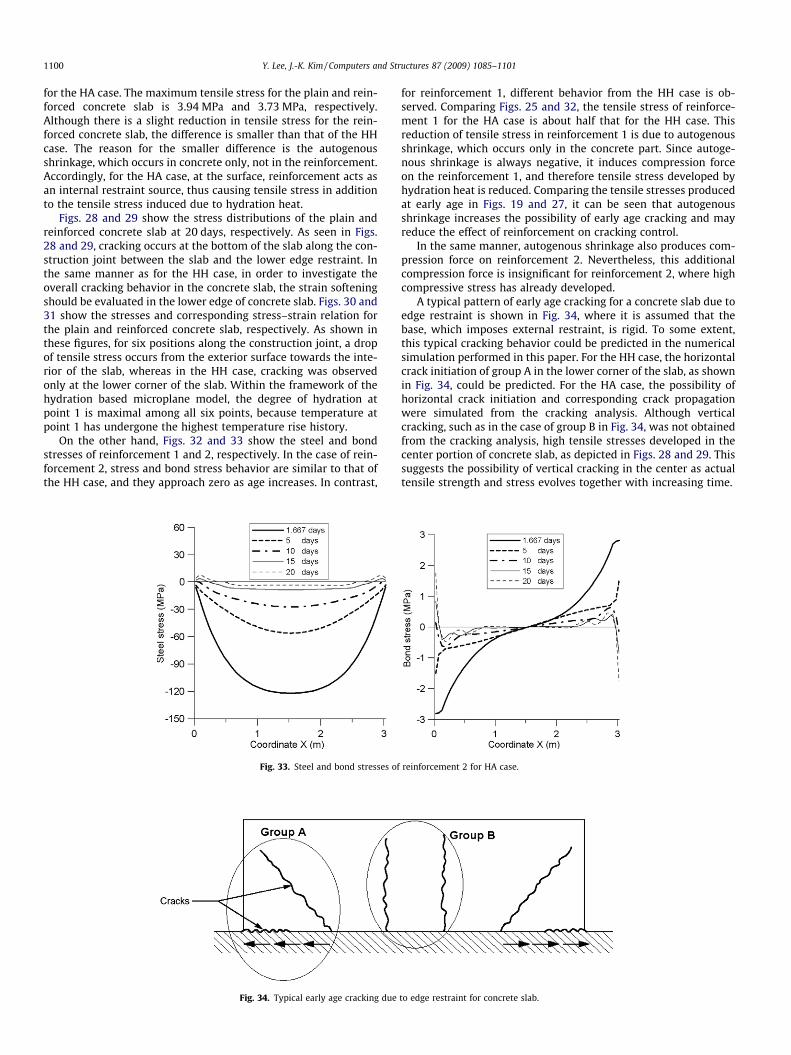
On the other hand, Figs. 32 and 33 show the steel and bondstresses of reinforcement 1 and 2, respectively. In the case of rein-forcement 2, stress and bond stress behavior are similar to that ofthe HH case, and they approach zero as age increases. In contrast,
Fig. 33. Steel and bond stresses of
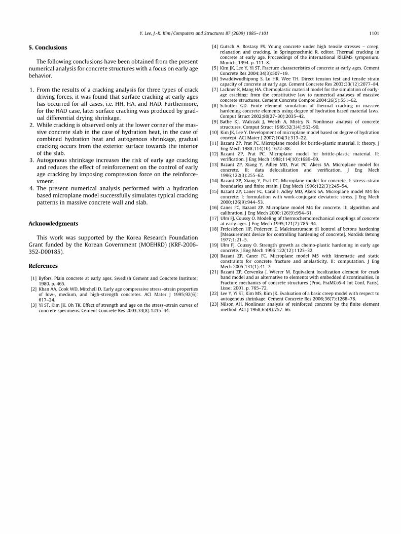
Fig. 34. Typical early age cracking due
for reinforcement 1, different behavior from the HH case is ob-served. Comparing Figs. 25 and 32, the tensile stress of reinforce-ment 1 for the HA case is about half that for the HH case. Thisreduction of tensile stress in reinforcement 1 is due to autogenousshrinkage, which occurs only in the concrete part. Since autoge-nous shrinkage is always negative, it induces compression forceon the reinforcement 1, and therefore tensile stress developed byhydration heat is reduced. Comparing the tensile stresses producedat early age in Figs. 19 and 27, it can be seen that autogenousshrinkage increases the possibility of early age cracking and mayreduce the effect of reinforcement on cracking control.
In the same manner, autogenous shrinkage also produces com-pression force on reinforcement 2. Nevertheless, this additionalcompression force is insignificant for reinforcement 2, where highcompressive stress has already developed.
A typical pattern of early age cracking for a concrete slab due toedge restraint is shown in Fig. 34, where it is assumed that thebase, which imposes external restraint, is rigid. To some extent,this typical cracking behavior could be predicted in the numericalsimulation performed in this paper. For the HH case, the horizontalcrack initiation of group A in the lower corner of the slab, as shownin Fig. 34, could be predicted. For the HA case, the possibility ofhorizontal crack initiation and corresponding crack propagationwere simulated from the cracking analysis. Although verticalcracking, such as in the case of group B in Fig. 34, was not obtainedfrom the cracking analysis, high tensile stresses developed in thecenter portion of concrete slab, as depicted in Figs. 28 and 29. Thissuggests the possibility of vertical cracking in the center as actualtensile strength and stress evolves together with increasing time.
reinforcement 2 for HA case.
to edge restraint for concrete slab.
Y. Lee, J.-K. Kim / Computers and Structures 87 (2009) 1085–1101 1101
5. Conclusions
The following conclusions have been obtained from the presentnumerical analysis for concrete structures with a focus on early agebehavior.
1. From the results of a cracking analysis for three types of crackdriving forces, it was found that surface cracking at early ageshas occurred for all cases, i.e. HH, HA, and HAD. Furthermore,for the HAD case, later surface cracking was produced by grad-ual differential drying shrinkage.
2. While cracking is observed only at the lower corner of the mas-sive concrete slab in the case of hydration heat, in the case ofcombined hydration heat and autogenous shrinkage, gradualcracking occurs from the exterior surface towards the interiorof the slab.
3. Autogenous shrinkage increases the risk of early age crackingand reduces the effect of reinforcement on the control of earlyage cracking by imposing compression force on the reinforce-vment.
4. The present numerical analysis performed with a hydrationbased microplane model successfully simulates typical crackingpatterns in massive concrete wall and slab.
Acknowledgments
This work was supported by the Korea Research FoundationGrant funded by the Korean Government (MOEHRD) (KRF-2006-352-D00185).
References
[1] Byfors. Plain concrete at early ages. Swedish Cement and Concrete Institute;1980. p. 465.
[2] Khan AA, Cook WD, Mitchell D. Early age compressive stress–strain propertiesof low-, medium, and high-strength concretes. ACI Mater J 1995;92(6):617–24.
[3] Yi ST, Kim JK, Oh TK. Effect of strength and age on the stress–strain curves ofconcrete specimens. Cement Concrete Res 2003;33(8):1235–44.
[4] Gutsch A, Rostasy FS. Young concrete under high tensile stresses – creep,relaxation and cracking. In Springenschmid R, editor. Thermal cracking inconcrete at early age, Proceedings of the international RILEMS symposium,Munich, 1994. p. 111–8.
[5] Kim JK, Lee Y, Yi ST. Fracture characteristics of concrete at early ages. CementConcrete Res 2004;34(3):507–19.
[6] Swaddiwudhipong S, Lu HR, Wee TH. Direct tension test and tensile straincapacity of concrete at early age. Cement Concrete Res 2003;33(12):2077–84.
[7] Lackner R, Mang HA. Chemoplastic material model for the simulation of early-age cracking: from the constitutive law to numerical analyses of massiveconcrete structures. Cement Concrete Compos 2004;26(5):551–62.
[8] Schutter GD. Finite element simulation of thermal cracking in massivehardening concrete elements using degree of hydration based material laws.Comput Struct 2002;80(27–30):2035–42.
[9] Bathe KJ, Walczak J, Welch A, Mistry N. Nonlinear analysis of concretestructures. Comput Struct 1989;32(3/4):563–90.
[10] Kim JK, Lee Y. Development of microplane model based on degree of hydrationconcept. ACI Mater J 2007;104(3):313–22.
[11] Bazant ZP, Prat PC. Microplane model for brittle-plastic material. I: theory. JEng Mech 1988;114(10):1672–88.
[12] Bazant ZP, Prat PC. Microplane model for brittle-plastic material. II:verification. J Eng Mech 1988;114(10):1689–99.
[13] Bazant ZP, Xiang Y, Adley MD, Prat PC, Akers SA. Microplane model forconcrete. II: data delocalization and verification. J Eng Mech1996;122(3):255–62.
[14] Bazant ZP, Xiang Y, Prat PC. Microplane model for concrete. I: stress–strainboundaries and finite strain. J Eng Mech 1996;122(3):245–54.
[15] Bazant ZP, Caner FC, Carol I, Adley MD, Akers SA. Microplane model M4 forconcrete: I: formulation with work-conjugate deviatoric stress. J Eng Mech2000;126(9):944–53.
[16] Caner FC, Bazant ZP. Microplane model M4 for concrete. II: algorithm andcalibration. J Eng Mech 2000;126(9):954–61.
[17] Ulm FJ, Coussy O. Modeling of thermochemomechanical couplings of concreteat early ages. J Eng Mech 1995;121(7):785–94.
[18] Freiesleben HP, Pedersen E. Maleinstrument til kontrol af betons hardening[Measurement device for controlling hardening of concrete]. Nordisk Betong1977;1:21–5.
[19] Ulm FJ, Coussy O. Strength growth as chemo-plastic hardening in early ageconcrete. J Eng Mech 1996;122(12):1123–32.
[20] Bazant ZP, Caner FC. Microplane model M5 with kinematic and staticconstraints for concrete fracture and anelasticity. II: computation. J EngMech 2005;131(1):41–7.
[21] Bazant ZP, Cervenka J, Wierer M. Equivalent localization element for crackband model and as alternative to elements with embedded discontinuities. InFracture mechanics of concrete structures (Proc, FraMCoS-4 Int Conf, Paris),Lisse; 2001. p. 765–72.
[22] Lee Y, Yi ST, Kim MS, Kim JK. Evaluation of a basic creep model with respect toautogenous shrinkage. Cement Concrete Res 2006;36(7):1268–78.
[23] Nilson AH. Nonlinear analysis of reinforced concrete by the finite elementmethod. ACI J 1968;65(9):757–66.