Chapter 15 Delamination Buckling in Composite Plates: an ...
Journal of Modern Processes in Manufacturing and Production, Vol. 6, No. 3, Summer 2017
87
Numerical Analysis of Delamination Buckling in Composite
Cylindrical Shell under Uniform External Pressure: Cohesive Element
Method
Sayed Ali Sajjady1, Saeed Rahnama2*, Mohammad Lotfi1, Reza Nosouhi3, 4
1 Department of Manufacturing, Faculty of Mechanical Engineering, University of Kashan, Kashan, Iran 2Department of Mechanical Engineering, Faculty of Mechanical Engineering, University of Birjand, Birjand, Iran
3Modern Manufacturing Technologies Research Center, Najafabad Branch, Islamic Azad University, Najafabad, Iran 4Department of Mechanical Engineering, Najafabad Branch, Islamic Azad University, Najafabad, Iran
*Email of Corresponding Author: [email protected] Received: September 18, 2017; Accepted: December 17, 2018
Abstract
Nowadays, due to high ratio of strength to weight, composite cylindrical shells are extensively used in a
great variety of different industrial applications and under different cases of loads. In this study, the
buckling of composite cylindrical shells was examined under uniform external pressure. The buckling
analysis of composite cylindrical shells was first done by using theoretical relationships. Doing this,
Donnell and improved Donnell equations were employed. Then finite element analysis of composite
cylindrical shells was done considering inter-layers delamination. Since delamination is a predominant
reason for damage in composite materials, considering different models, the effect of delamination and
the factors affecting it (such as the ratio of cylinder length to its cross-section perimeter, delamination
size, delamination depth location, and delamination shape) on critical buckling load will be examined.
Finally, in the section related to delamination growth, its growth direction and also the effect of
embedded delamination shape and size upon delamination growth were examined. The analysis of
variance of finite element results show that the area and the depth of delamination with the effectiveness
of % 31.92 and % 28.85 have respectively the most effects on critical buckling load. In this study, the
3D modeling of delamination and its growth by using cohesive elements is carried out in ABAQUS
software which is the main novelty of this work.
Keywords
Composite Cylindrical Shell, Buckling, Cohesive Element, Delamination Growth
1. Introduction
Over the past few decades, composites have been used numerously and in many cases have replaced
with conventional engineering materials. The most important of these replacements are using in
lightweight structures with high stress such as aircraft parts, sport equipment, oil equipment
offshore, underwater vehicles and offshore structures, under pressure vessels and so on [1-4]. The
main reasons for this choice include high strength, low weight, the specific resistance of these
materials against corrosive materials, lower costs, etc. [5]. In this study, the buckling of composite
cylindrical shells was examined under uniform external pressure. At first, using theoretical
relations, the critical buckling load is obtained manually. To this end, Donnell and improved
Donnell equations were used to obtain critical buckling loads of composite circular cylindrical
shells under uniform external pressure [6-8].

Numerical Analysis of Delamination Buckling in Composite Cylindrical Shell under Uniform External …, pp.87-106
88
Then finite element analysis of composite cylindrical shells was done. In recent years, using finite
element methods, composite cylindrical shells under uniform external pressure have been widely
studied [9-14]. Cai et al. [9], using probabilistic finite element method, analyzed the buckling of
long composite cylindrical. Since the reliability of composite cylindrical shells under uniform
external pressure cannot be estimated by using finite element method, to meet this need, they used
stochastic and probabilistic finite element analysis. In fact, they examined the effect of uncertainties
of mechanical properties and physical dimensions (that is significantly influenced by the
construction of composite materials and cylinder construction process) on the critical buckling
pressure.
Hur et al. [10, 11] compared the results of finite element analysis and hydrostatic pressure test to
study the buckling and post-buckling behaviors in composite cylinders. This comparison indicated
that the results are in good agreement with each other. Beside the experiments, White et al. [12]
used finite element analysis (linear and nonlinear) in order to evaluate the behavior of thin
composite structures (two variable-stiffness shells). It was examined under axial compression. The
prediction errors regarding buckling loads (0.4-7%) showed that the results were in good agreement
with the experimental one. Kepple et al. [13] represented a method to enhance stochastically
imperfections modeling in cylindrical thickness. At the end, they claimed that their results can
improve the design and reliability of untested cylindrical shells implementing thickness modeling.
In another study, prefect and perforated composite cylinders in terms of buckling behavior were
investigated in the numerical and experimental methods by Taheri-Behrooz et al. [14]. Their target
was to analyze the buckling behavior regarding initial geometrical imperfections. While the linear
finite element analysis had a significant errors compared to experiments, the nonlinear solution
showed acceptable results where single perturbation load coupled with linear buckling mode-shaped
imperfections strategies were carried out.
Rostami et al. [15-17] investigated the effect of different parameters of a composite lattice
cylindrical shell including physical properties of the material, shell thickness, and rib defects on
critical buckling load. Furthermore, these parameters were optimized by using finite element and
neural networks algorithm in order to reach high ratio of strength to weight.
In this paper, for finite element analysis, ABAQUS commercial software was used, and to do this,
both linear (linear perturbation-buckle) and nonlinear (nonlinear static, riks) buckling analysis were
performed. In nonlinear analysis, imperfection code and also the coefficients applied in
deformations modes of linear buckling analysis and their collection, as the structure's initial
deformation in nonlinear analysis, were used to make the conditions more real [18-20].
Then considering inter-layers delamination for composite cylindrical shells under uniform external
pressure, the finite element analysis of buckling was performed. Inter-layers delamination refers to
the positional separation of two adjacent layers that is made because of different reasons such as
stroke, installation, production process, and fatigue and so on in composite materials [21].Since
delamination is one of the predominant reasons of damage which reduces the load-bearing capacity
of the structure [22, 23], important effects of the delamination on the critical buckling load for
different parameters of composite cylindrical shells such as the ratio of cylinder length to its radius,
delamination shape, depth, and size were examined. Finally, in the section related to delamination

Journal of Modern Processes in Manufacturing and Production, Vol. 6, No. 3, Summer 2017
89
growth, its growth direction and also the effect of embedded delamination shape and size upon
delamination growth were examined.
Buckling is a phenomenon indicating the existence of instability within an under loading
component. For example, when the load applied to a component is rising, it is likely that one point
of the component getting instable and a sudden increase occurs in the point's displacements.
Buckling occurs both in elastic and plastic ranges; this means that the stresses in the component,
either elastic or plastic, make the buckling phenomenon likely to occur. Usually before buckling,
the ratio of the load to the displacement is to some extent that the component is called stable, but
after the onset of buckling, for every small change in the applied load, a large displacement is seen
at the point where the buckling has occurred. Hence, buckling is essentially a nonlinear
phenomenon [24].
As some studies reviewed above, it can be concluded that the modeling of delamination and its
growth by using cohesive elements in three dimensions was limitedly investigated. Therefore, in
this study, at first, using theoretical relationships, the buckling of composite cylindrical shells was
analyzed. Then, using ABAQUS commercial software, their linear and nonlinear finite element
analysis were performed. In the next steps, by using 3D cohesive elements (3D 8-nodes solid
composite elements (C3D8RC3)), delamination, delamination growth and the factors affecting them
in the buckling of composite cylindrical shells were examined.
2. Geometric Model
Schematic diagram of the composite cylindrical shell is shown in Figure 1, where R is the inner
radius of the cylinder and L is the cylinder length. The boundary conditions at the two ends of the
cylinder were regarded as simply support. Material properties of the layers and the middle layer are
given in Table1.The sequence of the composite shell layers is as [45º/0º/-45º/0º/45º/45º/0º/-
45º/0º/45º] and the thickness of each layer is as 0.00012m. H is the overall thickness of the
cylindrical shell and h is the thickness of the upper layer.
Figure1. Geometric model of composite cylindrical shell under uniform external pressure
Numerical Analysis of Delamination Buckling in Composite Cylindrical Shell under Uniform External …, pp.87-106
90
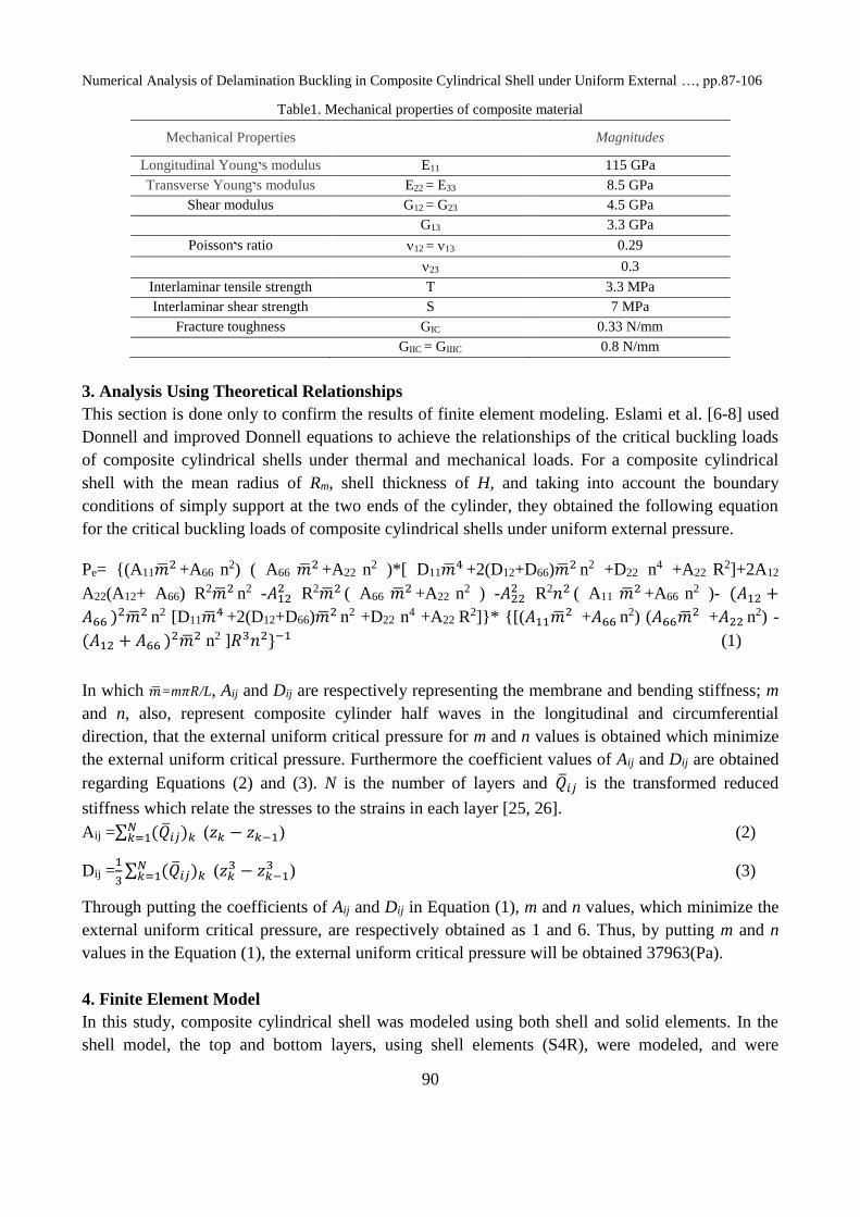
Table1. Mechanical properties of composite material
Mechanical Properties Magnitudes
Longitudinal Youngיs modulus E11 115 GPa
Transverse Youngיs modulus E22 = E33 8.5 GPa
Shear modulus G12 = G23 4.5 GPa
G13 3.3 GPa
Poissonיs ratio 12 = 13 0.29
23 0.3
Interlaminar tensile strength T 3.3 MPa
Interlaminar shear strength S 7 MPa
Fracture toughness GIC 0.33 N/mm
GIIC = GIIIC 0.8 N/mm
3. Analysis Using Theoretical Relationships
This section is done only to confirm the results of finite element modeling. Eslami et al. [6-8] used
Donnell and improved Donnell equations to achieve the relationships of the critical buckling loads
of composite cylindrical shells under thermal and mechanical loads. For a composite cylindrical
shell with the mean radius of Rm, shell thickness of H, and taking into account the boundary
conditions of simply support at the two ends of the cylinder, they obtained the following equation
for the critical buckling loads of composite cylindrical shells under uniform external pressure.
Pe= {(A11�̅�2 +A66 n2) ( A66 �̅�2 +A22 n2 )*[ D11�̅�4 +2(D12+D66)�̅�2 n2 +D22 n4 +A22 R2]+2A12
A22(A12+ A66) R2�̅�2 n2 -𝐴122 R2�̅�2 ( A66 �̅�2 +A22 n2 ) -𝐴22
2 R2𝑛2 ( A11 �̅�2 +A66 n2 )- (𝐴12 +
𝐴66 )2�̅�2 n2 [D11�̅�4 +2(D12+D66)�̅�2 n2 +D22 n
4 +A22 R2]}* {[(𝐴11�̅�2 +𝐴66 n
2) (𝐴66�̅�2 +𝐴22 n2) -
(𝐴12 + 𝐴66 )2�̅�2 n2 ]𝑅3𝑛2}−1 (1)
In which �̅�=m𝜋𝑅/L, Aij and Dij are respectively representing the membrane and bending stiffness; m
and n, also, represent composite cylinder half waves in the longitudinal and circumferential
direction, that the external uniform critical pressure for m and n values is obtained which minimize
the external uniform critical pressure. Furthermore the coefficient values of Aij and Dij are obtained
regarding Equations (2) and (3). N is the number of layers and �̅�𝑖𝑗 is the transformed reduced
stiffness which relate the stresses to the strains in each layer [25, 26].
Aij =∑ (�̅�𝑖𝑗)𝑘 𝑁𝑘=1 (𝑧𝑘 − 𝑧𝑘−1) (2)
Dij =1
3∑ (�̅�𝑖𝑗)𝑘
𝑁𝑘=1 (𝑧𝑘
3 − 𝑧𝑘−13 ) (3)
Through putting the coefficients of Aij and Dij in Equation (1), m and n values, which minimize the
external uniform critical pressure, are respectively obtained as 1 and 6. Thus, by putting m and n
values in the Equation (1), the external uniform critical pressure will be obtained 37963(Pa).
4. Finite Element Model
In this study, composite cylindrical shell was modeled using both shell and solid elements. In the
shell model, the top and bottom layers, using shell elements (S4R), were modeled, and were

Journal of Modern Processes in Manufacturing and Production, Vol. 6, No. 3, Summer 2017
91
attached to each other by surface to surface contact with cohesive behavior. In the Solid model, the
top and bottom layers, using 3D 8-nodes solid composite elements (C3D8RC3), were modeled, and
the connector between two layers was modeled using 3D 8-nodes cohesive elements (COH3D8), in
order to consider delamination and its growth in obtaining the external uniform critical pressure
more precisely. Cohesive element has been made from a volumetric element with no thickness
which has its own constitutive equations. Cohesive elements were placed in the zone surrounding
the delamination zone.
At the interface, to make a relation between the stress (𝜎) and the relative displacement (𝛿), the
cohesive constitutive equation is used. Based on Figure 2, the bilinear strain softening model which
is the most commonly used model, is applied here [27]. Load transferring even after the onset of
damage in cohesive zone is one of characteristics of used softening model. According to the figure,
the stress is as follows, if 𝛿 < 𝛿0:
𝜎 = 𝐾𝑝𝛿 (4)
In the second form, if 𝛿0 ≤ 𝛿 < 𝛿𝐹, then the stress is:
𝜎 = (1 − 𝐷)𝐾𝑝𝛿 (5)
Finally, the penalty stiffness is equal to zero, if 𝛿 ≥ 𝛿𝐹.
Figure2. The bilinear cohesive model
Apart from, surface to surface contact element was used in the delamination zone in order to avoid
overlaps between the elements.
In both Shell and Solid models, both linear (linear perturbation-buckling) and nonlinear (nonlinear
static, riks) buckling analyses were done. In nonlinear analysis, imperfection code and also the
coefficients applied in deformations modes of linear buckling analysis, and their collection, as the
structure’s initial deformation in nonlinear analysis, were used to make the conditions more real
[21]. In this study, 41 different models with different ratio of length to radius (L/R), delamination
size, delamination depth location, and delamination shape were examined, which are given in Table
2.

Numerical Analysis of Delamination Buckling in Composite Cylindrical Shell under Uniform External …, pp.87-106
92
5. Finite Element Analysis
5.1 Finite Element Analysis Regardless of Delamination
In this study, for finite element analysis, ABAQUS commercial software was used. At first, analysis
was performed regardless of embedded delamination in composite cylindrical shell under uniform
external pressure (see model No 1 in Table 2) both linearly and nonlinearly, so that the results can
be compared with the theoretical solution. Three important factors causing the buckling
phenomenon are:
1. Defects or imperfection in the structure of the component
2. Exclusion from the applied load centrality
3. The existence of lateral loads, even the small ones
In nonlinear analysis, if at least one of the above mentioned factors is not considered, the
component is not buckled and only is compressed. Thus, in nonlinear analysis, imperfection code
and the coefficients applied in deformations modes of linear buckling analysis, and their collection,
as the structure's initial deformation in nonlinear analysis, were used to make the conditions more
real [21]. In fact, imperfection code, through creating very small defects in the structure of the
component, causes the buckling phenomenon.
The applied coefficients which were multiplied in the deformation of the first five modes of linear
buckling analysis are respectively as 1e-6, 1e-6, 1e-6, 1e-6 and 1e-7, that the sum of these
deformations is used as the initial deformation in the nonlinear analysis. The critical pressure
obtained from the linear analysis is equal to 35825(Pa), and the critical pressure of the nonlinear
analysis (as can be seen in Figure 3) is equal to 33672(Pa) that the results are in a good agreement
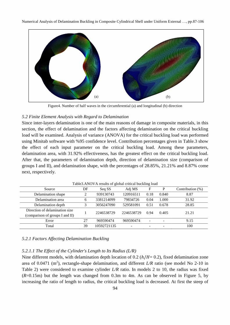
with the results of the theoretical solution. Likewise, both in the linear and nonlinear analysis, the
number of half waves in the longitudinal and circumferential direction (as can be seen in Figure 4)
was respectively obtained as 1 and 6 that are quite similar to the values of m and n of the theoretical
analysis.
Figure3. Diagram of critical buckling load in nonlinear analysis of Model No-1

Journal of Modern Processes in Manufacturing and Production, Vol. 6, No. 3, Summer 2017
93
Table2. Different Models of composite cylindrical shells and their Global critical buckling load
Model
No.
group Length
radius
ratio(L/
R)
Delamination
shape
Delamination
size â*b 0r
r(m)
Delamination
area(m2)
Delamination
depth
position(h/H)
Global
critical
buckling
load(Pa)
1 - 6.67 - -- - 33672
2 - 2 Rectangle 0.1571*0.3 0.0471 0.2 101614
3 - 3.33 Rectangle 0.1571*0.3 0.0471 0.2 60265
4 - 6.67 Rectangle 0.1571*0.3 0.0471 0.2 30874
5 - 10 Rectangle 0.1571*0.3 0.0471 0.2 25926
6 - 13.33 Rectangle 0.1571*0.3 0.0471 0.2 18090
7 - 16.67 Rectangle 0.1571*0.3 0.0471 0.2 12660
8 - 20 Rectangle 0.1571*0.3 0.0471 0.2 10805
9 - 23.33 Rectangle 0.1571*0.3 0.0471 0.2 10064
10 - 26.67 Rectangle 0.1571*0.3 0.0471 0.2 9735.5
11 I 20 Rectangle 0.1571*0.3 0.0471 0.2 10805
12 II 20 Rectangle 0.0942*0.5 0.0471 0.2 10855
13 I 20 Rectangle 0.2356*0.3 0.0707 0.2 10690
14 II 20 Rectangle 0.1414*0.5 0.0707 0.2 10732
15 I 20 Rectangle 0.3797*0.3 0.1139 0.2 10600
16 II 20 Rectangle 0.2278*0.5 0.1139 0.2 10641
17 I 20 Rectangle 0.2356*1 0.2356 0.2 9792.2
18 II 20 Rectangle 0.1178*2 0.2356 0.2 10479
19 I 20 Rectangle 0.4712*1 0.4712 0.2 9071.7
20 II 20 Rectangle 0.2356*2 0.4712 0.2 9273
21 I 20 Rectangle 0.9425*1 0.9425 0.2 7894
22 II 20 Rectangle 0.47125*2 0.9425 0.2 8247.3
23 II 20 Rectangle 0.9425*2 1.8850 0.2 6404.1
24 I 20 Ellipse 0.1999*0.3 0.0471 0.2 10715
25 II 20 Ellipse 0.1199*0.5 0.0471 0.2 10767
26 I 20 Ellipse 0.2998*0.3 0.0707 0.2 10607
27 II 20 Ellipse 0.1799*0.5 0.0707 0.2 10695
28 II 20 Ellipse 0.2899*0.5 0.1139 0.2 10412
29 II 20 Ellipse 0.1499*2 0.2356 0.2 10186
30 II 20 Ellipse 0.3*2 0.4712 0.2 8921
31 II 20 Ellipse 0.4712*2.5465
0.9425
0.2 7974
32 - 20 Circle 0.1225 0.0471 0.2 10648
33 - 20 Circle 0.14999 0.0707 0.2 10507
34 - 20 Rectangle 0.1571*0.3 0.0471 0.1 6864.9
35 - 20 Rectangle 0.1571*0.3 0.0471 0.2 10805
36 - 20 Rectangle 0.1571*0.3 0.0471 0.3 12231
37 - 20 Rectangle 0.1571*0.3 0.0471 0.5 14864
38 - 6.67 Rectangle 0.2356*0.3 0.0707 0.3 32876
39 - 6.67 Rectangle 0.4712*1 0.4712 0.3 29127
40 - 6.67 Ellipse 0.2998*0.3 0.0707 0.3 28878
41 - 6.67 Circle 0.149999 0.0707 0.3 28815
Numerical Analysis of Delamination Buckling in Composite Cylindrical Shell under Uniform External …, pp.87-106
94
Figure4. Number of half waves in the circumferential (a) and longitudinal (b) direction
5.2 Finite Element Analysis with Regard to Delamination
Since inter-layers delamination is one of the main reasons of damage in composite materials, in this
section, the effect of delamination and the factors affecting delamination on the critical buckling
load will be examined. Analysis of variance (ANOVA) for the critical buckling load was performed
using Minitab software with %95 confidence level. Contribution percentages given in Table.3 show
the effect of each input parameter on the critical buckling load. Among these parameters,
delamination area, with 31.92% effectiveness, has the greatest effect on the critical buckling load.
After that, the parameters of delamination depth, direction of delamination size (comparison of
groups I and II), and delamination shape, with the percentages of 28.85%, 21.21% and 8.87% come
next, respectively.
Table3.ANOVA results of global critical buckling load
Source DF Seq SS Adj MS F P Contribution (%)
Delamination shape 2 939130743 120916511 0.18 0.840 8.87
Delamination area 6 3381214099 79834726 0.04 1.000 31.92
Delamination depth 3 3056247090 529581091 0.51 0.678 28.85
Direction of delamination size
(comparison of groups I and II) 1 2246538729 2246538729 0.94 0.405 21.21
Error 27 969590474 969590474 - - 9.15
Total 39 10592721135 - - - 100
5.2.1 Factors Affecting Delamination Buckling
5.2.1.1 The Effect of the Cylinder's Length to Its Radius (L/R)
Nine different models, with delamination depth location of 0.2 (ℎ/𝐻= 0.2), fixed delamination zone
area of 0.0471 (m2), rectangle-shape delamination, and different L/R ratio (see model No 2-10 in
Table 2) were considered to examine cylinder L/R ratio. In models 2 to 10, the radius was fixed
(R=0.15m) but the length was changed from 0.3m to 4m. As can be observed in Figure 5, by
increasing the ratio of length to radius, the critical buckling load is decreased. At first the steep of

Journal of Modern Processes in Manufacturing and Production, Vol. 6, No. 3, Summer 2017
95
the changes is high, but for the L/R ratio of greater than 20 (ratio of cylinder length to its cross-
section perimeter of greater than 3) the steep of the changes is reduced or in the other words, the
values are converged. For this reason, to investigate the effect of the other affecting factors on
delamination, cylindrical models with L/R ratio of 20 are used.
Figure5. Variation of the critical buckling load as a function of L/R Ratio
5.2.1.2 The Effect of Delamination Area
In this study, 13 different models with delamination depth location of 0.2 (h/H=0.2), fixed L/R ratio
of 20 (L/R=20), rectangle-shape delamination, and different delamination size were used to examine
the effect of delamination size on the critical buckling load (see models 11-23 group I or II in Table
2). Obviously, by increasing delamination size, critical buckling pressure decreases [28] (see
Fig.6).Also, by increasing delamination size, buckling mode changes from global buckling
occurring directly to local buckling which occurs before global buckling; this is the reason of
reducing critical buckling load. By comparing the critical pressure of the models in the groups I and
II which have the same area of delamination zone, it can be understood that the models with more
delamination size in circumferential direction (�̂�) and less delamination size in longitudinal
direction (b), have less critical pressure. This suggests that delamination size in circumferential
direction more significantly influences at the reduction of the critical pressure in composite
cylindrical shells (compare critical pressure of the models 11&12, 13&14, 15&16, 17&18, 19&20,
21&22).Thus, it can be concluded that delamination growth in circumferential direction is more
difficult than delamination growth in longitudinal direction of the cylinder and needs more energy.
In other words, it can be said that the zone of embedded delamination will grow more in
longitudinal direction than in circumferential direction. As can be seen in Figure 7, critical pressure
in the models of the group I is less than critical pressure in the models of the group II. These results
also are correct for the models with embedded ellipse-shape delamination (compare critical pressure
of the models 24&25, 26&27).These results will be further investigated in the section related to
delamination growth.

Numerical Analysis of Delamination Buckling in Composite Cylindrical Shell under Uniform External …, pp.87-106
96
Figure6. Variation of the critical buckling load as a function of delamination area
Figure7. Variation of the critical buckling load of Models in Group I and II as a function of delamination area, Models
of Group II have more delamination size in circumferential direction (�̂�) and less delamination size in longitudinal
direction (b)
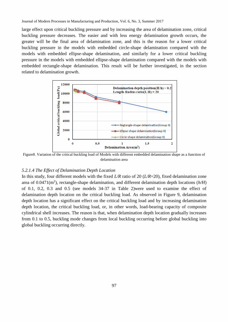
5.2.1.3 The Effect of Delamination Shape
In this paper, three shapes of delamination (rectangle, ellipse, and circle) were used as embedded
delamination zone. As can be observed in Figure 8, delamination shape has no enormous effect
upon critical buckling pressure, but generally it can be seen that critical buckling pressure in the
models with embedded circle-shape delamination is slightly less than the pressure in the models
with embedded ellipse-shape delamination; and the critical buckling pressure in the models with
embedded ellipse-shape delamination is slightly less than the pressure in the models with embedded
rectangle-shape delamination. Hence, it can be concluded that delamination growth in the models
with embedded circle-shape delamination is easier and needs less energy than the models with
embedded ellipse-shape delamination. Similarly, delamination growth in the models with embedded
ellipse-shape delamination is easier and needs less energy than the models with embedded
rectangle-shape delamination. As explained in previous section, the area of delamination zone has a
Journal of Modern Processes in Manufacturing and Production, Vol. 6, No. 3, Summer 2017
97
large effect upon critical buckling pressure and by increasing the area of delamination zone, critical
buckling pressure decreases. The easier and with less energy delamination growth occurs, the
greater will be the final area of delamination zone, and this is the reason for a lower critical
buckling pressure in the models with embedded circle-shape delamination compared with the
models with embedded ellipse-shape delamination, and similarly for a lower critical buckling
pressure in the models with embedded ellipse-shape delamination compared with the models with
embedded rectangle-shape delamination. This result will be further investigated, in the section
related to delamination growth.
Figure8. Variation of the critical buckling load of Models with different embedded delamination shape as a function of
delamination area
5.2.1.4 The Effect of Delamination Depth Location
In this study, four different models with the fixed L/R ratio of 20 (L/R=20), fixed delamination zone
area of 0.0471(m2), rectangle-shape delamination, and different delamination depth locations (h/H)
of 0.1, 0.2, 0.3 and 0.5 (see models 34-37 in Table 2)were used to examine the effect of
delamination depth location on the critical buckling load. As observed in Figure 9, delamination
depth location has a significant effect on the critical buckling load and by increasing delamination
depth location, the critical buckling load, or, in other words, load-bearing capacity of composite
cylindrical shell increases. The reason is that, when delamination depth location gradually increases
from 0.1 to 0.5, buckling mode changes from local buckling occurring before global buckling into
global buckling occurring directly.

Numerical Analysis of Delamination Buckling in Composite Cylindrical Shell under Uniform External …, pp.87-106
98
Figure9. Variation of the critical buckling load as a function of delamination depth location
5.2.2 Evaluation of Delamination Growth
5.2.2.1 Delamination Growth Direction
In this study, in order to evaluate delamination growth direction, a model with the L/R ratio of 6.67,
embedded rectangle-shape delamination, delamination depth location of 0.3 (h/H= 0.3), and
fixeddelamination zone area of 0.0707(m2) was used (see model 38 in Table 2). In each step, using
element removal technique, delamination growth was shown. As can be seen in Fig.10(a-i),
delamination growth occurs in the longitudinal direction of the cylinder and its width also increases
a little gradually. This result is completely in line with and confirms the result obtained in 5.2.1.2
section.
5.2.2.2 The Effect of Delamination Size upon Delamination Growth
For evaluating the effect of delamination size on delamination growth, two models with the L/R
ratio of 6.67, embedded rectangle-shape delamination, delamination depth location of 0.3 (h/H=
0.3), and different delamination zone area were used (see model 38 and 39 in Table 2). Comparing
the Figure 10(a-i) and 11(a-i), we find out that delamination size has no significant effect on the
shape of delamination growth; however, by increasing the area of delamination zone, delamination
growth occurs more. Likewise, by increasing the area of delamination zone (from 0.0707(m2) to
0.4712(m2)), delamination growth, instead of two points, starts from four points. In other words,
increasing delamination size, the number of delamination growth's starting points also increases that
is one of the reasons for decreasing the critical buckling load because of an increase in delamination
size.
5.2.2.3 The Effect of Delamination Shape upon Delamination Growth
Three different models with the L/R ratio of 6.67, delamination depth location of 0.3(h/H= 0.3),
fixed delamination zone area of 0.0707(m2), and embedded different-shapes delamination
(rectangle, circle, and ellipse) were used to examine the effect of delamination shape on
delamination growth (see model 38, 40 and 41 in Table 2). Comparing the Figure 10(a-i), 112(a-i)

Journal of Modern Processes in Manufacturing and Production, Vol. 6, No. 3, Summer 2017
99
and 13(a-i), it is found that shape of delamination growth in these three models is the same. In other
words, embedded delamination shape has no effect on the shape of delamination growth. However,
since circle-shape and ellipse-shape delamination zone are more similar to the shape of
delamination growth, delamination growth in the models with embedded circle-shapes delamination
and embedded ellipse-shapes delamination is easier and needs less energy than the models with
embedded rectangle-shape delamination. Therefore, critical buckling load in the models with
embedded circle-shapes delamination and embedded ellipse-shapes delamination is less than the
models with embedded rectangle-shape delamination. This result is completely in line with and
confirms the result obtained in 5.2.1.3 section.
Likewise, comparing the Figure 10(a-i), 12(a-i) and 13(a-i) which have the same area of
delamination zone, it is observed that in the models with embedded rectangle-shape delamination
(model 38 in Table 2), delamination growth starts from two points, while, in the models with
embedded circle-shapes delamination and embedded ellipse-shapes delamination (models 40 and 41
in Table 2), delamination growth starts from four points. It is because in the fixed area of
delamination zone of 0.0707(m2), models with embedded circle-shapes delamination and embedded
ellipse-shapes delamination have more delamination size in circumferential direction (2r=
0.29999m for circle-shape, �̂�= 0.2998m for ellipse-shape) than the models with embedded
rectangle-shape delamination (�̂�= 0.2356m for rectangle-shape), and as before said, delamination
size in circumferential direction (compared with delamination size in longitudinal direction) has
more effect on the buckling of composite cylindrical shells. Therefore, increasing the number of
starting points of delamination growth is another reason for the lower critical buckling load in the
models with embedded circle-shapes delamination and embedded ellipse-shapes delamination than
the models with embedded rectangle-shape delamination.
6. Conclusion
In this study, using both theoretical relations and finite element analysis, the buckling of composite
cylindrical shells under uniform external pressure was successfully examined. In finite element
analysis using cohesive elements, the 3D modeling of delamination and its growth in ABAQUS
software was examined which is the main novelty of this study.
Such factors as cylinderיs ratio of L/R, delamination size, and delamination depth location have a
great effect on the critical buckling load in composite cylindrical shells under uniform external
pressure.
By increasing the ratio of L/R, the critical buckling pressure decreases, in which the steep of these
changes is high at the beginning but for a greater than 20 L/R ratio, steep of the changes decreases
or in the other words, the values are converged.
As the area of delamination zone increases, critical buckling pressure decreases. Also, among the
models which have the same area of delamination zone, the model with more delamination size in
circumferential direction (�̂�) and less delamination size in longitudinal direction (b) has less critical
buckling pressure. In other words, delamination size in circumferential direction has more effect on
reducing critical buckling load.
As delamination depth location increases, critical buckling load also increases. The reason is that,
buckling mode changes from local buckling occurring into global buckling occurring directly.

Numerical Analysis of Delamination Buckling in Composite Cylindrical Shell under Uniform External …, pp.87-106
100
Through examining the models, the following results about delamination growth in composite
cylindrical shells under uniform external pressure were obtained.
1. Delamination growth occurs more in longitudinal direction and its width (in circumferential
direction) also increases a little gradually.
2. The analysis of variance of finite element results reveal that the most effective parameters on
critical buckling load are the area and the depth of delamination in which their effectiveness are
% 31.92 and % 28.85, respectively.
3. By increasing the area of delamination zone, more delamination growth occurs and also
delamination growth starts from more points.
4. The shape of delamination growth is more similar to ellipse. Therefore, in the models with
embedded circle-shapes delamination and embedded ellipse-shapes delamination, as
delamination shape is more similar to the shape of delamination growth, delamination growth
occurs easier and uses less energy than the models with embedded rectangle-shape
delamination.
5. Among the models with the same area of delamination zone, in the models with more
delamination size in circumferential direction, more delamination growth occurs and also
delamination growth starts from more points.

Journal of Modern Processes in Manufacturing and Production, Vol. 6, No. 3, Summer 2017
101
Figure10. Delamination growth evolution of Model No-38 with rectangle-shape delamination and area of delamination
zone of 0.0707(m2)

Numerical Analysis of Delamination Buckling in Composite Cylindrical Shell under Uniform External …, pp.87-106
102
Figure11. Delamination growth evolution of Model No-39 with rectangle-shape delamination and area of delamination
zone of 0.4712(m2)

Journal of Modern Processes in Manufacturing and Production, Vol. 6, No. 3, Summer 2017
103
Figure12. Delamination growth evolution of Model No-40 with ellipse-shape delamination and area of delamination
zone of 0.0707(m2)

Numerical Analysis of Delamination Buckling in Composite Cylindrical Shell under Uniform External …, pp.87-106
104
Figure13. Delamination growth evolution of Model No-41 with circle-shape delamination and area of delamination
zone of 0.0707(m2)

Journal of Modern Processes in Manufacturing and Production, Vol. 6, No. 3, Summer 2017
105
7. References
[1] Ross, C.T. 2006. A Conceptual Design of an Underwater Vehicle. Ocean Engineering. 33(16):
2087-2104.
[2] Ochoa, O.O. and Salama, M.M. 2005. Offshore Composites: Transition Barriers to an Enabling
Technology. Composites Science and Technology. 65: 2588-96.
[3] Alexander, C. and Ochoa, O.O. 2010. Extending Onshore Pipeline Repair to Offshore Steel
Risers with Carbon–Fiber Reinforced Composites. Composite Structures. 92: 499-507.
[4] Zeleniakienė, D., Griškevičius, P., Leišis, V. and Milašienė, D. 2010. Numerical Investigation of
Impact Behaviour of Sandwich Fiber Reinforced Plastic Composites. Mechanika. 5(85): 31-36.
[5] Matthews, F.L. and Rawlings, R.D. 1999. Composite Materials: Engineering and Science: CRC
Press.
[6] Eslami, M. and Javaheri, R. 1999. Buckling of Composite Cylindrical Shells under Mechanical
and Thermal Loads. Journal of Thermal Stresses. 22: 527-45.
[7] Eslami, R. A. 1992. Variational Approach to Elastic--Plastic Buckling of Cylindrical shells.
Verband Technischen Uberwachungs-Vereine e V(Germany). 1: 241-53.
[8] Eslami, M. and Shariyat, M. 1997. Elastic, Plastic, and Creep Buckling of Imperfect Cylinders
under Mechanical and Thermal Loading. Journal of Pressure Vessel Technology. 119(1): 27-36.
[9] Cai, B., Liu, Y., Li, H. and Li, Z. 2011. Buckling Analysis of Composite Long Cylinders Using
Probabilistic Finite Element Method. Mechanika. 17(5): 467–473.
[10] Moon, C-J., Kim, I-H., Choi, B-H., Kweon, J-H. and Choi, J-H. 2010. Buckling of Filament-
Wound Composite Cylinders Subjected to Hydrostatic Pressure for Underwater Vehicle
Applications. Composite Structures. 92(9): 2241-2251.
[11] Hur, S-H., Son, H-J., Kweon, J-H. and Choi, J-H. 2008. Postbuckling of Composite Cylinders
under External Hydrostatic Pressure. Composite Structures. 86(1-3): 114-24.
[12] White, S. C., Weaver, P. M. and Wu, K. C. 2015. Post-Buckling Analyses of Variable-Stiffness
Composite Cylinders in Axial Compression. Composite Structures. 123: 190-203.
[13] Kepple, J., Prusty, B. G., Pearce, G., Kelly, D. and Thomson, R. 2014. Improved Methods for
Modeling Imperfections for Buckling Analysis of Composite Cylindrical Shells. In 29th
Congress of the International Council of the Aeronautical Sciences. 2108-2120.
[14] Taheri-Behrooz, F., Omidi, M. and Shokrieh, M. M. 2017. Experimental and Numerical
Investigation of Buckling Behavior of Composite Cylinders with Cutout. Thin-Walled
Structures. 116: 136-144.
[15] Yazdi, M., Latifi-Rostami, S., Kolahdooz, A. 2016. Optimization of Geometrical Parameters in
a Specific Composite Lattice Structure Using Neural Networks and ABC Algorithm. Journal of
Mechanical Science & Technology. 30(4): 1763-1771.
[16] Alashti, R.A., Rostami, S.L., Rahimi, G. 2012 . Buckling Analysis of Composite Lattice
Cylindrical Shells with Ribs Defects. International Journal of Engineering-Transactions A:
Basics. 26(4): 411-420.
[17] Latifi-Rostami, S., Akbari-Alashti, R. and Kolahdooz, A. 2015. The Effect of Geometrical
Parameters of Cylindrical Composite Lattice Structures on Buckling Behavior. Journal of
Simulation and Analysis of Novel Technologies in Mechanical Engineering. 8(3): 197-207.
Numerical Analysis of Delamination Buckling in Composite Cylindrical Shell under Uniform External …, pp.87-106
106
[18] Shariati, M., Sedighi, M., Saemi, J., Eipakchi, H. and Allahbakhsh, H. 2010. Numerical and
Experimental Investigation on Ultimate Strength of Cracked Cylindrical Shells Subjected to
Combined Loading. Mechanika. 4(84): 12-19.
[19] Tafreshi, A. 2006. Delamination Buckling and Postbuckling in Composite Cylindrical Shells
under Combined Axial Compression and External Pressure. Composite Structures. 72(4): 401-
418.
[20] Graham, D. 1995. Composite Pressure Hulls for Deep Ocean Submersibles. Composite
Structures. 32(1-4): 331-343.
[21] Arbocz, J. 1987. Post-Buckling Behaviour of Structures Numerical Techniques for More
Complicated Structures. Buckling and Post-Buckling: Springer. 83-142.
[22] Wohlever, J. 1999. Some Computational Aspects of a Group Theoretic Finite Element
Approach to the Buckling and Postbuckling Analyses of Plates and Shells of Revolution.
Computer Methods in Applied Mechanics and Engineering. 170(3-4): 373-406.
[23] Abaqus keywords Reference Manual. 2: I-z 2010, 9.3: 30-34
[24] Mistry, J., Gibson, A. and Wu, Y-S. 1992. Failure of Composite Cylinders under Combined
External Pressure and Axial Loading. Composite Structures. 22(4): 193-200.
[25] Tafreshi, A. and Oswald, T. 2003. Global Buckling Behaviour and Local Damage Propagation
in Composite Plates with Embedded Delaminations. International Journal of Pressure Vessels
and Piping. 80(1): 9-20.
[26] Jones, R.M. 1998. Mechanics of Composite Materials: CRC Press.
[27] Wang, R., Zhang, L., Zhang, J., Liu, W. and He, X. 2010. Numerical Analysis of Delamination
Buckling and Growth in Slender Laminated Composite using Cohesive Element Method.
Computational Materials Science. 50(1): 20-31.
[28] Chirica, I. and Beznea, E-F. 2011. Buckling Analysis of the Composite Plates with
Delaminations. Computational Materials Science. 50(5): 1587-1591.