Numerical analysis of bevel gear forming - NUMIFORM …numiform2016.utt.fr/Papers/104.pdf · In...
6
1 Corresponding author: [email protected] Numerical analysis of bevel gear forming Jaroslaw Bartnicki 1 1 Lublin University of Technology 38D Nadbystrzycka, 20-618 Lublin, Poland Abstract. In this paper the numerical analysis of bevel gear forming is presented. Simulations are made by means of FEM using Deform 3D software. Distributions of stress, strain, temperature and Cockroft - Latham damage criterion are presented at various process parameters. Obtained shape of final part and calculated loads during the process course can be useful for the further industrial applications. 1 Introduction The problematic of different mechanical elements with teeth forming is really complex. Among several manufacturing technologies there is a choice between machining or metal forming methods. Rarely the casting technologies are applied, but their role begins to be marginal. The choice between different machining technologies is connected with time of manufacturing, which is really the most important factor in cost calculation. Due to this reason, in wider scope of applications (especially in mass production) the metal forming technologies find their place. The other requirements are also connected with different fields of applications as aviation or automotive industry with special norms concerning manufacturing methods. Presently, thinking about durability and elevated mechanical properties of different parts with teeth the forging or rolling processes are widely applied. In the case of forging technology many parts are formed as preform by rolling or forging. Finally these parts are forged with flash. In minority of forging plants forging with flash is replaced by process without flash. This tendency permits to reduce wastes and time loss due to additional flash trimming operation. The advantage of this process is also in continuity of material into the forging. 2 Bevel gear forming 2.1 Traditional forging Presently in one of the Polish industry plant bevel gear part, presented in Figure 1, is traditionally forged in two operations. This automotive element is firstly prepared as cylindrical bar, which is heated and upset in the first operation. In the second operation it is possible to obtain final part with flash which is trimmed in additional stand. Normally, these kinds of parts are made in series between 10000 – 20000 pieces on one command. Figure 1. Schema of bevel gear. This “traditional” forging technology has many advantages. Among them it is worth to notice that it is possible to apply bars or preforms with some height and diameter tolerances. The process can be realized using different machines – presses and hammers and obtained final parts have relatively good repeatability. This very important factor is connected with possible to obtain close manufacturing tolerances, which permit to decrease final machining of obtained bevel gears. Normally in the presented case the material allowances can be limited to 0.3 – 0.4 mm. During machining ,due to non continuous
Transcript of Numerical analysis of bevel gear forming - NUMIFORM …numiform2016.utt.fr/Papers/104.pdf · In...

1 Corresponding author: [email protected]
Numerical analysis of bevel gear forming
Jaroslaw Bartnicki1
1Lublin University of Technology 38D Nadbystrzycka, 20-618 Lublin, Poland
Abstract. In this paper the numerical analysis of bevel gear forming is presented. Simulations are made by means of
FEM using Deform 3D software. Distributions of stress, strain, temperature and Cockroft - Latham damage criterion
are presented at various process parameters. Obtained shape of final part and calculated loads during the process
course can be useful for the further industrial applications.
1 Introduction
The problematic of different mechanical elements with
teeth forming is really complex. Among several
manufacturing technologies there is a choice between machining or metal forming methods. Rarely the casting
technologies are applied, but their role begins to be
marginal.
The choice between different machining technologies
is connected with time of manufacturing, which is really
the most important factor in cost calculation. Due to this
reason, in wider scope of applications (especially in mass
production) the metal forming technologies find their
place.
The other requirements are also connected with
different fields of applications as aviation or automotive industry with special norms concerning manufacturing
methods. Presently, thinking about durability and
elevated mechanical properties of different parts with
teeth the forging or rolling processes are widely applied.
In the case of forging technology many parts are formed
as preform by rolling or forging. Finally these parts are
forged with flash. In minority of forging plants forging
with flash is replaced by process without flash. This
tendency permits to reduce wastes and time loss due to
additional flash trimming operation. The advantage of
this process is also in continuity of material into the
forging.
2 Bevel gear forming
2.1 Traditional forging
Presently in one of the Polish industry plant bevel gear
part, presented in Figure 1, is traditionally forged in two
operations. This automotive element is firstly prepared as
cylindrical bar, which is heated and upset in the first
operation. In the second operation it is possible to obtain
final part with flash which is trimmed in additional stand.
Normally, these kinds of parts are made in series between
10000 – 20000 pieces on one command.
Figure 1. Schema of bevel gear.
This “traditional” forging technology has many
advantages. Among them it is worth to notice that it is
possible to apply bars or preforms with some height and
diameter tolerances. The process can be realized using
different machines – presses and hammers and obtained final parts have relatively good repeatability. This very
important factor is connected with possible to obtain
close manufacturing tolerances, which permit to decrease
final machining of obtained bevel gears. Normally in the
presented case the material allowances can be limited to
0.3 – 0.4 mm. During machining ,due to non continuous

MATEC Web of Conferences
contact between cutting blades of tools, in this case these
allowances are bigger (usually about 0.8 mm) This
allows obtaining better machining conditions, limiting
vibrations and increasing lifetime of machining tools [1-
5].
2.1 Proposed solution
One of the biggest problems in industry is the proper
choice of manufacturing technological parameters. The optimal range of forming forces, speeds and temperatures
decide about costs and time of the proposed process.
Parallely, the same rule have additional operations, which
are also very important.
The modern forging technologies are focused on
reduction of wastes, operations and operating time. One
of the solutions for obtaining these gains concern close
die forging technologies without flash, the second are
connected with near net shape. The terms informs about
very close to the final (net) shape of parts. It reduces ,of
course ,the need for surface finishing as machining or
grinding. The proposition for bevel gear parts is the numerical calculations presented in this paper. Analysis
concerns stage of preform manufacturing from upset
cylindrical bar – shown in Figure 2 and final bevel gear
forging –shown in Figure 3. The dies for final forging
stage are presented in Figure 4.
Figure 2. Preform forging from upset cylindrical bar
(initial position and final stage)
Figure 3. Final bevel gear forging from preform (initial position and final stage)
Figure 4. Final bevel gear dies: bottom die (left) and
upper die (right)
3 Numerical simulation
3.1 Software, process conditions and numerical model
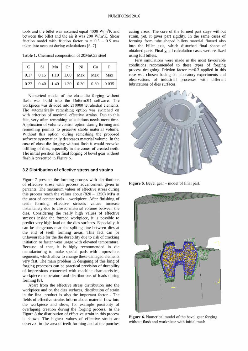
Numerical calculations of the close die forging without flash process of bevel gear realized with the application
of software Deform3D, according to the model of final
part given in Figure 5, were discussed. In order to achieve
the result the most similar to the real one, it was decided
that the process would take place in conditions of heat
exchange with the environment. Material model of steel
20MnCr5 (Table 1) was taken from software library,
modified and finally described as:
(1)
where: – flow stress; - strain; – strain rate
and – temperature.
The initial temperature of the billet was form the range between (1000÷1150)ºC with steps by 50ºC. The
forming dies (modelled as rigid bodies) temperature was
assumed 150ºC. The heat exchange coefficient between
NUMIFORM 2016
tools and the billet was assumed equal 4000 W/m2K and
between the billet and the air it was 200 W/m2K. Shear
friction model with friction factor m = 0.3 – 0.5 was
taken into account during calculations [6, 7].
Table 1. Chemical composition of 20MnCr5 steel
C Si Mn Cr Ni Cu P
0.17 0.15 1.10 1.00 Max Max Max
0.22 0.40 1.40 1.30 0.30 0.30 0.035
Numerical model of the close die forging without
flash was build into the Deform3D software. The
workpiece was divided into 210000 tetrahedral elements.
The automatically remeshing option was switched on
with criterion of maximal effective strains. Due to this
fact, very often remeshing calculations needs more time.
Application of volume control option during forming and
remeshing permits to preserve stable material volume.
Without this option, during remeshing the proposed
software systematically decreases material volume. In the
case of close die forging without flash it would provoke
infilling of dies, especially in the zones of created teeth. The initial position for final forging of bevel gear without
flash is presented in Figure 6.
3.2 Distribution of effective stress and strains
Figure 7 presents the forming process with distributions
of effective stress with process advancement given in
percents. The maximum values of effective stress during
this process reach the values about (820 – 1350) MPa at
the area of contact tools – workpiece. After finishing of teeth forming, effective stresses values increase
instantanely due to closed material volume between the
dies. Considering the really high values of effective
stresses inside the formed workpiece, it is possible to
predict very high load on the dies surfaces. Especially, it
can be dangerous near the spliting line between dies at
the end of teeth forming areas. This fact can be
unfavourable for the die durability due to risk of cracking
initiation or faster wear usage with elevated temperature.
Because of that, it is higly recommended in die
manufacturing to make special pads with impressions
segments, which allow to change these damaged elements very fast. The main problem in designing of this king of
forging processes can be practical prevision of durability
of impressions connected with machine characteristics,
workpiece temperature and distributions of loads during
forming [8].
Apart from the effective stress distribution into the
workpiece and on the dies surfaces, distribution of strain
in the final product is also the important factor . The
fields of effective strains inform about material flow into
the workpiece and show, for example possiblity of
overlaping creation during the forging process. In the Figure 8 the distribution of effective strain in this process
is shown. The highest values of effective strain are
observed in the area of teeth forming and at the punches
acting areas. The core of the formed part stays without
strain, yet, it gives part rigidity. In the same cases of
forming from tube shaped billets material flowed also
into the billet axis, which disturbed final shape of
obtained parts. Finally, all calculation cases were realized
using full billets.
First simulations were made in the most favourable
conditions recommended to these types of forging
process designing. Friction factor m=0.3 applied in this
case was chosen basing on laboratory experiments and
observations of industrial processes with different lubrications of dies surfaces.
Figure 5. Bevel gear – model of final part.
Figure 6. Numerical model of the bevel gear forging
without flash and workpiece with initial mesh

MATEC Web of Conferences
Figure 7. Effective stress distribution during forging with
initial temperature 1150ºC and friction factor m = 0.3
3.3 Influence of temperature range and friction factor values
Presented in the Figure 7 and 8 distributions of effective
stress and strains were obtained in the most favourable
process conditions taken into consideration in assumptions. Beginning the process with recommended
temperature of material 1150ºC it was possible to finish
forging at 940ºC. All forming cycle took 4,5 seconds,
which was in accordance with industrial possibilities of
the press proposed for this process. Changing the
conditions as lowering the temperature of workpiece or
taking into calculations dies with initial environment
temperature 20ºC can be dangerous for virtually designed
impressions. For the initial workpiece temperature
1000ºC the end of the forming process was calculated
with temperature of the final part about 830ºC. At the same time, the effective stress into the final part reached
1350 MPa and observed loads can be dangerous for dies
impressions. In the Figure 9 and 10 distributions of
effective stresses in workpiece during forming and loads
on tools with different initial temperatures are shown. In
all presented in this diagram effective stress distributions
initial temperature of dies was 150ºC. The biggest values
of effective stresses were noticed at the punch front area
and near the biggest part’s diameter. Analysing the
process beginning with ―cold‖ dies at 20ºC, the final
temperature of the obtained bevel gear part will be
relatively lower than in stable manufacturing stage. With
the part temperature about 720ºC (workpiece initial
temperature in this case was 1000ºC) it is almost certain
to damage fixed in the press tools. Applying during the
forming process different friction factors allowed to
verify the influence of lubrication on dies impressions
filled by metal. Proposed to the simulations friction factor
value m = 0.3 in all different temperatures variants was
satisfactory and provided to obtain final part with correct
shapes. Almost the same results were observed with the
higher friction factor value m = 0.4. Comparing the same simulations steps, it was possible to observe a little
slower filling of the dies impressions. Greater change was
noticed with application of friction factor m = 0.5. In this
case it was really problematic to finish the process before
final dies closing. Actually, it cannot be observed in
practise because of constant material volume in all the
analysed cases. However, in worked out simulations this
observation informs about possible difficulties in real
process without proper lubrication [9-10].
Figure 8. Effective strain distribution during forging with
initial temperature 1150ºC and friction factor m = 0.3
3.4 Cockroft – Latham criterion
During the calculation also the damage criterion was
verified. In the Deform3D software there are several
damage criteria but the most popular is Cockroft Latham
integral, which calculated value informs about the risk of
crack presence inside the formed part.

NUMIFORM 2016
Basing on experience and literature research it can be
stated that in the case of hot metal forming conditions for
steels during forging process accepted values of this
integral are about 0.7 – 0.8. In the Figure 11, the results
of numerical calculations using Cockroft–Latham integral
at final simulations steps, are presented.
Figure 9. Effective stress distribution during forging with
marked initial workpiece temperatures
Figure 10. Loads on dies distribution during forging with
marked initial workpiece temperatures
Observed distribution of Cockroft – Latham damage
criterion allows for crack initiation predictions. In the
most favourable composition of the highest initial
temperature of workpiece and the lowest friction factor it can be possible to obtain part with relatively reduced risk
of internal faults presence. But all changes of the
mentioned above process parameters can disturb the
process by increasing probability of internal cracks
propagation. Due to this fact, all parts applied in
automotive and aviation industry must be checked by non
destructive tests. Presented simulations results showed
only that the risk of part failure during manufacturing
process is real and must be verified in laboratory and
further industrial tests before application in
manufacturing program of forging plant.
Figure 11. Cockroft – Latham integral values calculated in simulations realised with marked friction factors and
initial workpiece temperatures
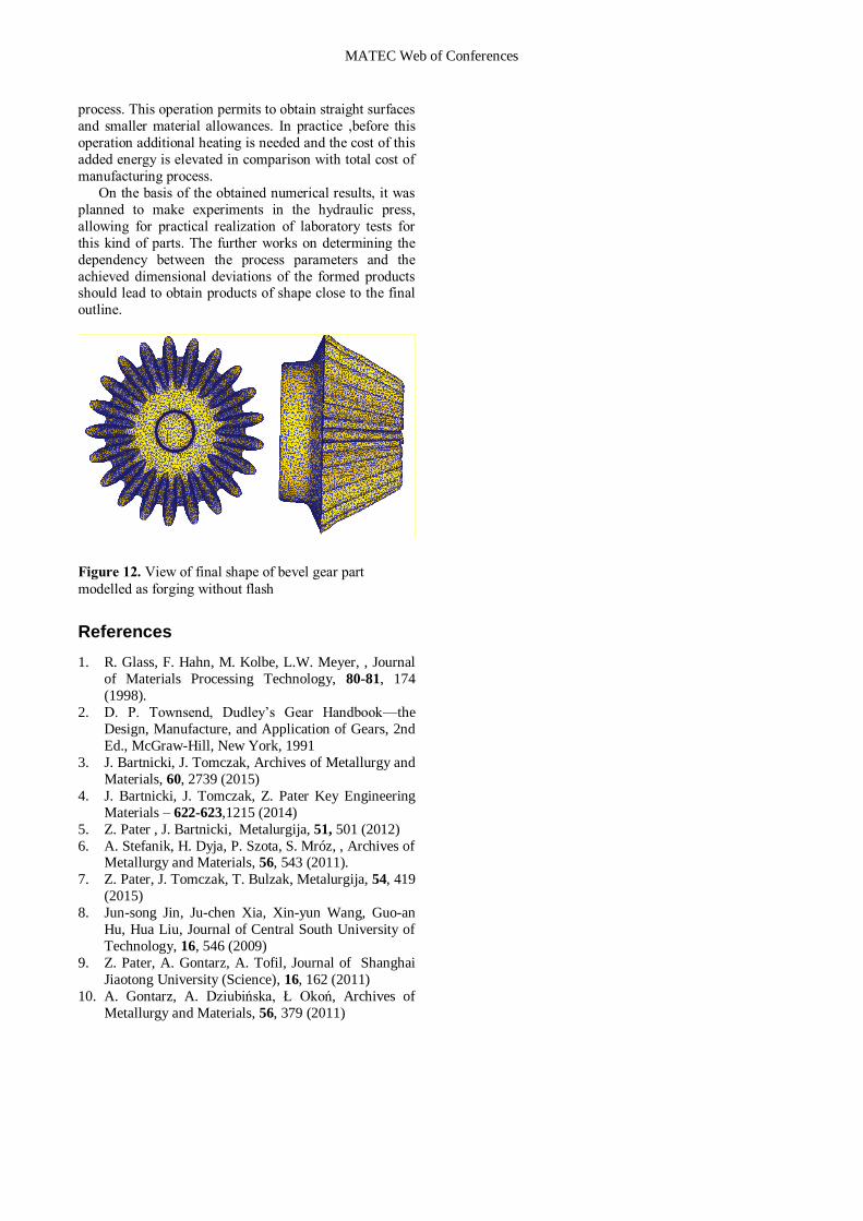
4. Summary
The conducted numerical calculations show the
possibility of forming of bevel gear by means of close die
forging without flash on parts from steel 20MnCr5.
Presented in Figure 12 final shape of bevel gear part
modelled as forging without flash show very close
dimensional accuracy to the proposed model of the final part. Presented in this Figure teeth have a correct contour,
which reflect die impressions. In many proposed solution
the last stage of this kind of forming is additional sizing
Time, s
Effective stress, MPa
Load, kN
Time, s
MATEC Web of Conferences
process. This operation permits to obtain straight surfaces
and smaller material allowances. In practice ,before this
operation additional heating is needed and the cost of this
added energy is elevated in comparison with total cost of
manufacturing process.
On the basis of the obtained numerical results, it was
planned to make experiments in the hydraulic press,
allowing for practical realization of laboratory tests for
this kind of parts. The further works on determining the
dependency between the process parameters and the
achieved dimensional deviations of the formed products should lead to obtain products of shape close to the final
outline.
Figure 12. View of final shape of bevel gear part
modelled as forging without flash
References
1. R. Glass, F. Hahn, M. Kolbe, L.W. Meyer, , Journal
of Materials Processing Technology, 80-81, 174
(1998).
2. D. P. Townsend, Dudley’s Gear Handbook—the
Design, Manufacture, and Application of Gears, 2nd
Ed., McGraw-Hill, New York, 1991
3. J. Bartnicki, J. Tomczak, Archives of Metallurgy and
Materials, 60, 2739 (2015)
4. J. Bartnicki, J. Tomczak, Z. Pater Key Engineering
Materials – 622-623,1215 (2014)
5. Z. Pater , J. Bartnicki, Metalurgija, 51, 501 (2012)
6. A. Stefanik, H. Dyja, P. Szota, S. Mróz, , Archives of Metallurgy and Materials, 56, 543 (2011).
7. Z. Pater, J. Tomczak, T. Bulzak, Metalurgija, 54, 419
(2015)
8. Jun-song Jin, Ju-chen Xia, Xin-yun Wang, Guo-an
Hu, Hua Liu, Journal of Central South University of
Technology, 16, 546 (2009)
9. Z. Pater, A. Gontarz, A. Tofil, Journal of Shanghai
Jiaotong University (Science), 16, 162 (2011)
10. A. Gontarz, A. Dziubińska, Ł Okoń, Archives of
Metallurgy and Materials, 56, 379 (2011)