Numerical Analysis for a Mobile Explosive Chamber ... of a MEC subjected to internal blast loads,...
13
Australian Journal of Basic and Applied Sciences, 11(7) May 2017, Pages: 84-96 AUSTRALIAN JOURNAL OF BASIC AND APPLIED SCIENCES ISSN:1991-8178 EISSN: 2309-8414 Journal home page: www.ajbasweb.com Open Access Journal Published BY AENSI Publication © 2017 AENSI Publisher All rights reserved This work is licensed under the Creative Commons Attribution International License (CC BY). http://creativecommons.org/licenses/by/4.0/ To Cite This Article: Nada M.Nagy, Gamal H.Mahmoud, Mohamed M.ElShafey., Numerical Analysis for a Mobile Explosive Chamber subjected to internal blast loading. Aust. J. Basic & Appl. Sci., 11(7): 84-96, 2017 Numerical Analysis for a Mobile Explosive Chamber subjected to internal blast loading 1 Nada M.Nagy, 2 Gamal H.Mahmoud, 3 Mohamed M.ElShafey 1 Nada M.Nagy, BSc, Civil Engineering Department, Ain Shams University, Teaching Assistant, Canadian International College, Cairo, Egypt. 2 Gamal H.Mahmoud, Associate Professor, Civil Engineering Department, Ain Shams University, Cairo, Egypt. 3 Mohamed M.ElShafey, Assistant Professor, Head of Civil Engineering Department, Canadian International College, Cairo, Egypt. Address For Correspondence: Nada M.Nagy, Ain shams University, Civil Department, Faculty of Engineering, Cairo. Egypt. ARTICLE INFO ABSTRACT Article history: Received 18 February 2017 Accepted 5 May 2017 Available online 10 May 2017 Keywords: Internal blast Loading, Charge weight, AUTODYN, Deformation, Explosive chamber. Recently, blast loads have received more attention since the events of September 11 th 2001. The Police officers at the Bomb Squad department are mainly responsible for ensuring public safety. The hard work circumstances results in large number of injuries and fatalities. The increase in the number of injuries and fatalities drives the need of Mobile Explosive Chamber (MEC). The main purpose of the MEC is to contain the blast hazards to insure safely detonation. This paper represents numerical analysis and design of a MEC subjected to internal blast loads, using ANSYS AUTODYN commercial software. Parameters such as different wall chamber thickness and mass of explosive charge were studied. The model construction for air, TNT explosive charge and MEC is described in details. The MEC was tested for 2kg and 5kg of TNT using various thicknesses 10, 20 and 30 mm. The results show that the MEC thickness has an influence effect on maximum displacement and maximum strain of MEC. The predicted quasi-static pressure from AUTODYN simulation agrees with experimental and empirical relationships given in literature. A comparison between the maximum strain and displacement using various thicknesses with different charges is represented. Also, the MEC has a significant contribution in decreasing the pressure values in case of the chamber failure. The attenuation of the pressure is represented after the chamber failure. It was found that the MEC existence delays the arrival time of the shock wave and decays the peak incident pressure value by a significant percentage. For tested MEC, it was found that increasing the MEC thickness results in decreasing the plastic strain and displacement of MEC by significant values. In some cases increasing the MEC thickness prevents the MEC from failure. INTRODUCTION Recently, blast loads have received more attention since the events of September 11 th 2001, because of accidental or intentional events related to important structures(Remennikov 2003). The police officers at the bomb squad department are mainly responsible for ensuring the safety and protecting communities from hazard of any explosive charges. They work under hard circumstances and they deal with suspected items every day that result in large number of injuries and fatalities between those police officers. The main risk of these charges is mainly affecting the police officers of bomb squad department. Generally speaking, the consequences of explosive charges are incident and reflected pressure, primary and secondary fragments, debris, fireball and crater. These consequences can cause collapsing of the whole structure, loss of life and injuries (Ngo, Mendis et al. 2007) and (Elshafey.M.M 2008).The increase in the number of injuries and fatalities between those police
-
Upload
vuongthien -
Category
Documents
-
view
220 -
download
1
Transcript of Numerical Analysis for a Mobile Explosive Chamber ... of a MEC subjected to internal blast loads,...
Australian Journal of Basic and Applied Sciences, 11(7) May 2017, Pages: 84-96
AUSTRALIAN JOURNAL OF BASIC AND
APPLIED SCIENCES
ISSN:1991-8178 EISSN: 2309-8414
Journal home page: www.ajbasweb.com
Open Access Journal Published BY AENSI Publication © 2017 AENSI Publisher All rights reserved This work is licensed under the Creative Commons Attribution International License (CC BY). http://creativecommons.org/licenses/by/4.0/
To Cite This Article: Nada M.Nagy, Gamal H.Mahmoud, Mohamed M.ElShafey., Numerical Analysis for a Mobile Explosive Chamber
subjected to internal blast loading. Aust. J. Basic & Appl. Sci., 11(7): 84-96, 2017
Numerical Analysis for a Mobile Explosive Chamber subjected to internal
blast loading 1Nada M.Nagy, 2Gamal H.Mahmoud, 3Mohamed M.ElShafey
1Nada M.Nagy, BSc, Civil Engineering Department, Ain Shams University, Teaching Assistant, Canadian International College, Cairo,
Egypt. 2Gamal H.Mahmoud, Associate Professor, Civil Engineering Department, Ain Shams University, Cairo, Egypt. 3Mohamed M.ElShafey, Assistant Professor, Head of Civil Engineering Department, Canadian International College, Cairo, Egypt.
Address For Correspondence: Nada M.Nagy, Ain shams University, Civil Department, Faculty of Engineering, Cairo. Egypt.
A R T I C L E I N F O A B S T R A C T
Article history:
Received 18 February 2017 Accepted 5 May 2017
Available online 10 May 2017
Keywords: Internal blast Loading, Charge weight,
AUTODYN, Deformation, Explosive
chamber.
Recently, blast loads have received more attention since the events of September 11th
2001. The Police officers at the Bomb Squad department are mainly responsible for ensuring public safety. The hard work circumstances results in large number of injuries
and fatalities. The increase in the number of injuries and fatalities drives the need of
Mobile Explosive Chamber (MEC). The main purpose of the MEC is to contain the blast hazards to insure safely detonation. This paper represents numerical analysis and
design of a MEC subjected to internal blast loads, using ANSYS AUTODYN
commercial software. Parameters such as different wall chamber thickness and mass of explosive charge were studied. The model construction for air, TNT explosive charge
and MEC is described in details. The MEC was tested for 2kg and 5kg of TNT using
various thicknesses 10, 20 and 30 mm. The results show that the MEC thickness has an
influence effect on maximum displacement and maximum strain of MEC. The
predicted quasi-static pressure from AUTODYN simulation agrees with experimental
and empirical relationships given in literature. A comparison between the maximum strain and displacement using various thicknesses with different charges is represented.
Also, the MEC has a significant contribution in decreasing the pressure values in case
of the chamber failure. The attenuation of the pressure is represented after the chamber failure. It was found that the MEC existence delays the arrival time of the shock wave
and decays the peak incident pressure value by a significant percentage. For tested
MEC, it was found that increasing the MEC thickness results in decreasing the plastic strain and displacement of MEC by significant values. In some cases increasing the
MEC thickness prevents the MEC from failure.
INTRODUCTION
Recently, blast loads have received more attention since the events of September 11th 2001, because of
accidental or intentional events related to important structures(Remennikov 2003). The police officers at the
bomb squad department are mainly responsible for ensuring the safety and protecting communities from hazard
of any explosive charges. They work under hard circumstances and they deal with suspected items every day
that result in large number of injuries and fatalities between those police officers. The main risk of these charges
is mainly affecting the police officers of bomb squad department. Generally speaking, the consequences of
explosive charges are incident and reflected pressure, primary and secondary fragments, debris, fireball and
crater. These consequences can cause collapsing of the whole structure, loss of life and injuries (Ngo, Mendis et
al. 2007) and (Elshafey.M.M 2008).The increase in the number of injuries and fatalities between those police

85 Nada M.Nagy et al, 2017
Australian Journal of Basic and Applied Sciences, 11(7) May 2017, Pages: 84-96
officers derives the need of MEC. Examples for police officers accidents are given in (The.guardian
2010),(Daily.mail 2015) and (Dialy.news.Egypt 2016).The main purpose of the MEC is to contain the blast
waves and the explosive material to protect the society against blast wave effects (Karlsson.D 2013). The
analysis and design of structures subjected to blast loads require a detailed understanding of blast phenomena
and the dynamic response of various structural elements(Ngo, Mendis et al. 2007), (Tavakoli and Kiakojouri
2014). The internal blast loading of a structure is significantly different from the external and free air blast
loading (BakerW 1983), (Beshara.FBA 1994), (Smith and Rose 2002) and (Feldgun, Karinski et al. 2016). A
comparison between the confined and free air explosion is explained in detail. The Finite Element Analysis
programs become widely used to simulate and describe real life situations in a similar way. This paper
represents numerical analysis and design of a MEC subjected to internal blast loads, using ANSYS AUTODYN
commercial software.
Model Construction:
Air Domain:
The 3-D air domain was represented with ideal gas equation of state using Euler-FCT solver. The “flow-
out” boundary condition was applied along the air domain sides and top to prevent wave reflection and allow the
transmission of the shock waves (Theory Manual for AUTODYN 2003, n.d.), except on the ground surface
connected to the MEC as this was a reflective boundary (no-flow out condition). The ground surface reflection
is modelled by the bottom side of the Euler mesh, while the gas and air are allowed to escape across the
boundaries of three other sides. The air domain size is 1500 mm in Y and Z directions and 1000 mm in X
direction with 50 mm mesh resolution. Explosive Charges; Two explosive charges 2kg and 5kg of TNT were
used for all models after remapping stage. Remapping is used to detonate the amount of specific explosive in 1-
D to the point of interest and then transforming to 3-D models. In this research, the point of interest represented
at 360 mm from the center of the explosion charge. The end time was recorded in the 1-D model to use it lately
as the starting time in the 3-D models. This step will help in decreasing the run time in the 3-D models. The
radius of the spherical charge is determined by knowing the mass of charge using the following equation
(Elshafey.M.M 2008);
r = √𝟑∗𝒘∗𝟏𝟎𝟎𝟎
𝟏.𝟔𝟑∗𝟒∗𝝅
𝟑 (1)
The insertion point for the 3-D models is the center of the explosive chamber to represent the actual
position of charges. The coordinates of insertion point is X=0, Y=0 and Z=0.The first stage of the 3-D model
construction for the MEC was done through explicit dynamics then it was transferred to AUTODYN, as the
geometry is not available directly in AUTODYN application. As the MEC is a thin section shell solver is used
to model the explosive chamber in the 3-D models as the time step is controlled by the segment length not the
thickness so no problem termination will occur with large displacement through the analysis (Theory Manual for
AUTODYN 2003, n.d.). Effects of various parameters such as the chamber wall thickness, and explosive charge
mass are studied. The results show that chamber wall thickness has a significant influence on the response. MEC
is a half spherical steel chamber with different wall thickness. The MEC is restrained at the three directions X, Y
and Z as shown in Fig. 1 (a). The chambers dimensions and weights are as shown in
Table 1. Different gauges locations were used at the MEC surface to obtain the deformation as shown in
Fig. 1 (b). (Gauge 33 at X=360 mm, Gauge 40 at X=200 mm, Gauge 46 at X=15 mm).
Table 1: Mobile explosive chambers dimensions and weight.
ME
C
Model Diameter (mm) MEC thickness (mm) Volume (cm3) Weight (kg)
10MEC
720
10 843.5 64
20MEC 20 16290 128
30MEC 30 24443 192
86 Nada M.Nagy et al, 2017
Australian Journal of Basic and Applied Sciences, 11(7) May 2017, Pages: 84-96
.
(a) (b) Fig. 1: MEC boundary conditions and movable gauges locations.
1.1 Material properties:
The material properties for the air, TNT and steel 4340 were used according to AUTODYN material
library. Steel 4340 represents the “High strength steel” in AUTODYN library, yield stress fy= 4.00E+5kPa and
bulk modulus K= 2.00E+8kPa. The failure model for steel 4340 was defined as a plastic strain value of 0.2,
while the erosion model was defined as a geometric strain value of 0.2. The erosion model was used to prevent
the program termination due to expected large deformations (Theory Manual for AUTODYN 2003, n.d.) and
(Elshafey.M.M 2008).
1.2 Pressure in the free air:
The main objective of measuring the pressure in the free air is to perform the effect of the blast chamber
existence in attenuating the pressure in the case of complete failure. A pressure gauge (gauge 10) was set at 1m
from the explosive charge center to track the pressure values in the free air without any obstacles. Fig. 2 (a) and
Fig. 2 (b) show the pressure time history for the air for 2kg and 5kg TNT at (gauge 10) respectively. For 2kg
TNT detonation the shock wave reaches gauge 10 at 0.56m.s with incident pressure of 823 kPa, while for the
5kg detonation the shock wave reaches gauge 10 at 0.43m.s with incident pressure of 1450 kPa.
(a) 2kg TNT (b) 5kg TNT
Fig. 2: Pressure-time history in the free air at gauge 10.
1.3 Pressure in confined space:
The internal blast loading a structure is significantly different from the external and free air blast loading.
The major difference between internal and external explosion is the quasi-static pressure (Pqs) (Smith and Rose
2002). (Pqs) occurs after the initial stage of peak pressure and reflected pressures. In case of fully containment
the stage of (Pqs) remains constant for a large period of time, while it decays in case of vented structure (BakerW
1983), (Beshara.FBA 1994), (Feldgun, Karinski et al. 2016). Fig. 3 shows the typical pressures-time history for
a fully confined structure (Feldgun, Karinski et al. 2016). A pressure gauge was set inside the MEC at (X=250,
Y=0.0, Z=0.0) to represent the internal pressure-time history. Fig. 4 shows the pressure time history for 2kg and
5kg TNT explosive charges detonated inside the MEC respectively. For the 2kg TNT the measured incident
pressure is 5266 kPa at time 0.06m.s, while the reflected pressure is 37464 kPa at time 0.22m.s. The measured
quasi-static pressure is 22000 kPa. For the 5kg TNT the measured incident pressure is 13576 kPa at time

87 Nada M.Nagy et al, 2017
Australian Journal of Basic and Applied Sciences, 11(7) May 2017, Pages: 84-96
0.06m.s, while the reflected pressure is 91671 kPa at time 0.21m.s. The measured quasi-static pressure is 54000
kPa. The reflected pressure is approximately 7 times the incident pressure for the 2 cases. The obtained
pressure- time history inside the chamber from AUTODYN, agree with the typical pressure-time history for a
fully confined structure as shown in Fig. 3. It completely different from the obtained pressure-time history in the
free air showed in Fig. 2, as there were no reflected pressure and quasi-static pressure but the peak incident
pressure returns after very short time to the ambient pressure value.
Fig. 3: The typical pressures-time history for a fully confined structure (Feldgun, Karinski et al. 2016).
(a) 2kg TNT (b) 5kg TNT
Fig. 4: The pressure-time history inside the MEC.
1.4 Quasi-static pressure in confined space:
The prediction of the quasi-static pressure as a function of the weight of explosive charge (W) to the free
volume of structure (V) was given by different sources based on empirical and experimental relationships
(BakerW 1983), (Beshara.FBA 1994) and (Feldgun, Karinski et al. 2016). The free volume of the MEC is equal
to 0.1 m3. Table 2 shows the predicted Pqs for two different W/V ratios result from AUTODYN simulation. As
shown in Fig. 5 and Fig. 7 the predicted values of Pqs from AUTODYN agree with the predicted values given in
(Feldgun, Karinski et al. 2016).
Table 2: Predicted Pqs from AUTODYN simulation.
W (kg) V (m3) W/V (kg /m3) Pqs (kPa)
2 0.1
20 22000
5 50 54000
88 Nada M.Nagy et al, 2017
Australian Journal of Basic and Applied Sciences, 11(7) May 2017, Pages: 84-96
Fig. 5: Peak quasi-static pressure as a function of W/V, empirical relationships (Feldgun, Karinski et al. 2016).
Fig. 6: Peak quasi-static pressure as a function of W/V, experimental relationships (Feldgun, Karinski et al.
2016).
1.5 Mesh study:
Mesh study is done to verify the adequate mesh size for the air domain and for the MEC to achieve a
good compromise between mesh resolution and computational time. Mesh study results for air results were
compared to (Elshafey.M.M 2008) as shown in Fig. 7 (a). The mesh size equal to or less than 50 mm results
would be the best agreement with (Elshafey.M.M 2008) results. For the MEC Fig. 7 (b) shows the measured
displacement at gauge 33, using different mesh sizes (5, 15, 20 mm). The 5 and 15 mm mesh sizes yield almost
the same displacement while 20 mm mesh size a little differs, suggesting that the results are not sensitive to the
mesh size smaller than 15 mm. For the MEC the used mesh size is 15 mm.
(a) (b)
Fig. 7: Influence of mesh size.
89 Nada M.Nagy et al, 2017
Australian Journal of Basic and Applied Sciences, 11(7) May 2017, Pages: 84-96
MEC Models Results:
The internal blast load produces large amplitudes of shock wave reflections from the surface, results in a
high strain rates. After the shock wave hits the surface plastic deformation occurs. The re-reflected pressure
values are decays with time and they are always less than the first reflected shock (BakerW 1983). The next
section shows the MEC models results.
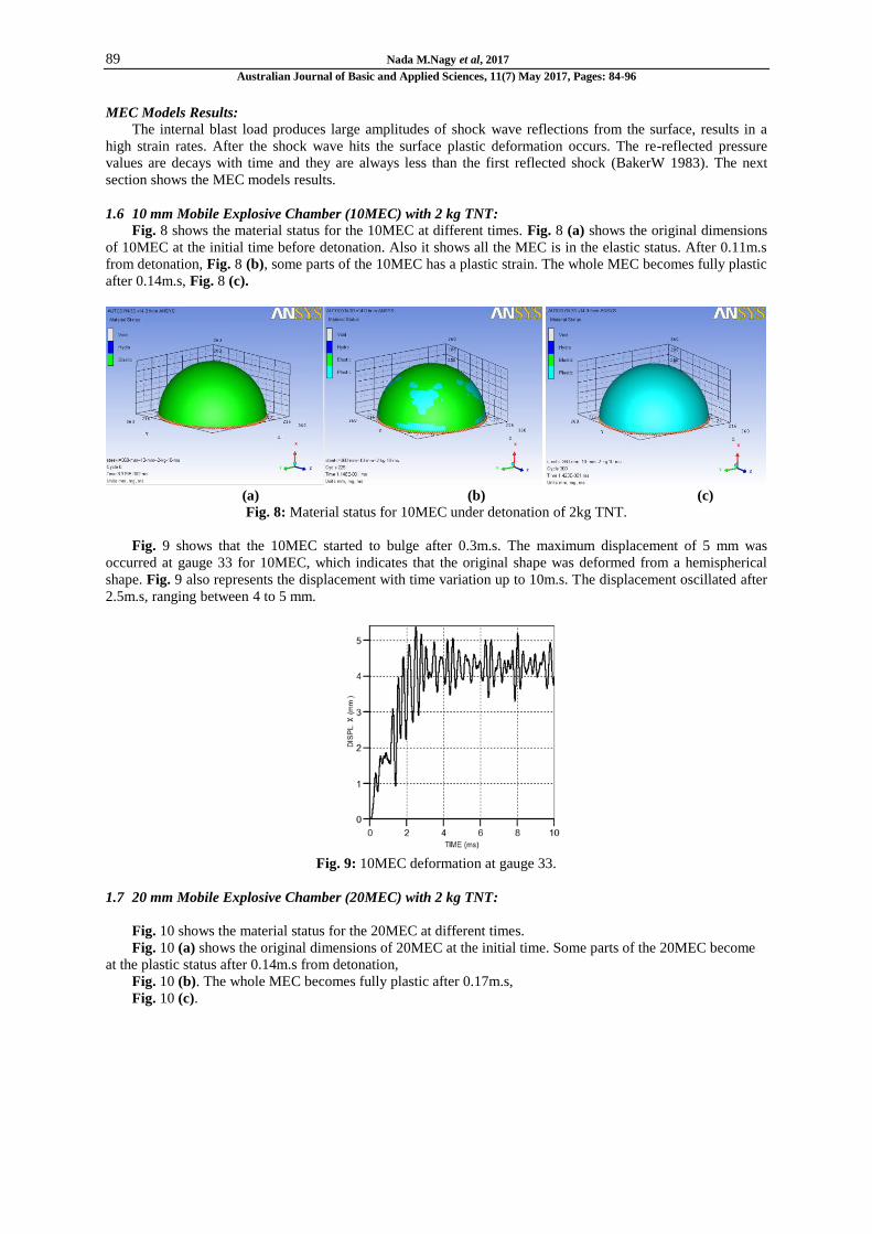
1.6 10 mm Mobile Explosive Chamber (10MEC) with 2 kg TNT:
Fig. 8 shows the material status for the 10MEC at different times. Fig. 8 (a) shows the original dimensions
of 10MEC at the initial time before detonation. Also it shows all the MEC is in the elastic status. After 0.11m.s
from detonation, Fig. 8 (b), some parts of the 10MEC has a plastic strain. The whole MEC becomes fully plastic
after 0.14m.s, Fig. 8 (c).
(a) (b) (c)
Fig. 8: Material status for 10MEC under detonation of 2kg TNT.
Fig. 9 shows that the 10MEC started to bulge after 0.3m.s. The maximum displacement of 5 mm was
occurred at gauge 33 for 10MEC, which indicates that the original shape was deformed from a hemispherical
shape. Fig. 9 also represents the displacement with time variation up to 10m.s. The displacement oscillated after
2.5m.s, ranging between 4 to 5 mm.
Fig. 9: 10MEC deformation at gauge 33.
1.7 20 mm Mobile Explosive Chamber (20MEC) with 2 kg TNT:
Fig. 10 shows the material status for the 20MEC at different times.
Fig. 10 (a) shows the original dimensions of 20MEC at the initial time. Some parts of the 20MEC become
at the plastic status after 0.14m.s from detonation,
Fig. 10 (b). The whole MEC becomes fully plastic after 0.17m.s,
Fig. 10 (c).

90 Nada M.Nagy et al, 2017
Australian Journal of Basic and Applied Sciences, 11(7) May 2017, Pages: 84-96
(a) (b) (c)
Fig. 10: Material status for 20MEC under detonation of 2kg TNT.
Fig. 11 represents the displacement with time variation for the 20MEC up to 10m.s at gauge 33. The
maximum displacement at gauge 33 for 20MEC is 1.72 mm.
Fig. 11: 20MEC deformation at gauge 33.
1.8 30 mm Mobile Explosive Chamber (30MEC) with 2 kg TNT:
The original dimensions of 30MEC at the initial time as shown in Fig. 12 (a). After 0.18m.s from
detonation, some parts of the 30MEC have a plastic strain, Fig. 12 (b). After 10m.s, Fig. 12 (c) shows that some
parts of the 30MEC still in the elastic state and there is no obvious change in the dimensions of the 30MEC
which indicates that, increasing thickness of the MEC results in decreasing the plastic strain and deformations.
(a) (b) (c)
Fig. 12: Material status for 30MEC under detonation of 2kg TNT.
Fig. 13 represents the displacement with time variation for the 30MEC up to 10m.s at gauge 33. the
maximum displacement for 30MEC is 1.5mm. After 0.8m.s, the displacement oscillates between very small
values from 0 to 1 mm.

91 Nada M.Nagy et al, 2017
Australian Journal of Basic and Applied Sciences, 11(7) May 2017, Pages: 84-96
Fig. 13: 30MEC deformation at gauge 33.
1.9 10 mm Mobile Explosive Chamber (10MEC) with 5 kg TNT:
By increasing the charge weight to 5kg TNT 10MEC fails after 0.58m.s.
Fig. 14 (a) shows the 10MEC at the initial time. After 0.09m.s from detonation, some parts of the 10MEC
have a plastic strain,
Fig. 14 (b).
Fig. 14 (c) shows the whole 10MEC have been in the plastic status after 0.11m.s. After 0.53m.s,
Fig. 14 (d) shows the obvious change in dimensions of the 10MEC from the original which indicates that,
10MEC was deformed from a hemispherical shape just after 0.53m.s by a significant value. After this time the
10MEC starts to fail. Fig. 15 shows the 10MEC failure sequence up to 10m.s.
(a) (b)
(c) (d)
Fig. 14: Material status for 10MEC under detonation of 5kg TNT.
92 Nada M.Nagy et al, 2017
Australian Journal of Basic and Applied Sciences, 11(7) May 2017, Pages: 84-96
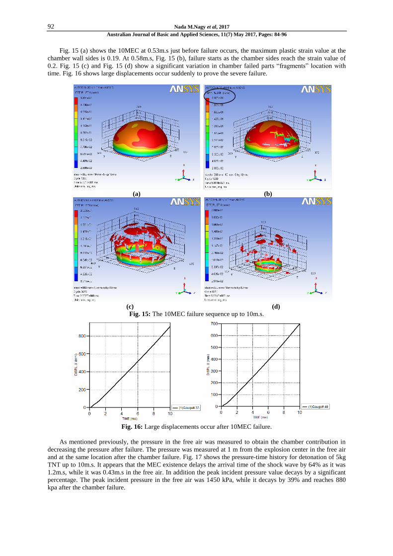
Fig. 15 (a) shows the 10MEC at 0.53m.s just before failure occurs, the maximum plastic strain value at the
chamber wall sides is 0.19. At 0.58m.s, Fig. 15 (b), failure starts as the chamber sides reach the strain value of
0.2. Fig. 15 (c) and Fig. 15 (d) show a significant variation in chamber failed parts “fragments” location with
time. Fig. 16 shows large displacements occur suddenly to prove the severe failure.
(a) (b)
(c) (d)
Fig. 15: The 10MEC failure sequence up to 10m.s.
Fig. 16: Large displacements occur after 10MEC failure.
As mentioned previously, the pressure in the free air was measured to obtain the chamber contribution in
decreasing the pressure after failure. The pressure was measured at 1 m from the explosion center in the free air
and at the same location after the chamber failure. Fig. 17 shows the pressure-time history for detonation of 5kg
TNT up to 10m.s. It appears that the MEC existence delays the arrival time of the shock wave by 64% as it was
1.2m.s, while it was 0.43m.s in the free air. In addition the peak incident pressure value decays by a significant
percentage. The peak incident pressure in the free air was 1450 kPa, while it decays by 39% and reaches 880
kpa after the chamber failure.

93 Nada M.Nagy et al, 2017
Australian Journal of Basic and Applied Sciences, 11(7) May 2017, Pages: 84-96
Fig. 17: Pressure-time history for 5 kg TNT at gauge 10.
1.10 20 mm Mobile Explosive Chamber (20MEC) with 5 kg TNT:
Fig. 18 shows the material status for the 20MEC at different times after detonation of 5kg TNT. Fig. 18 (a)
shows the original dimensions of 20MEC. Some parts of the 20MEC have a plastic strain after 0.10m.s from
detonation, Fig. 18 (b). The whole MEC becomes fully plastic after 0.12m.s, Fig. 18 (c).
(a) (b) (c)
Fig. 18: Material status for 20MEC under detonation of 5kg TNT.
Fig. 19 represents the displacement with time variation for the 20MEC up to 10m.s, it shows that the
20MEC started to deform from the hemispherical shape after 0.34m.s, and the maximum displacement occurred
at gauge 33 for 20MEC is 7.2 mm.
Fig. 19: 20MEC deformation at gauge 33.
1.11 30 mm Mobile Explosive Chamber (30MEC) with 5 kg TNT:
The original dimensions of 30MEC at the initial time as shown in Fig. 20 (a). After 0.11m.s from
detonation, some parts of the 30MEC have a plastic strain, Fig. 20 (b). After 0.14m.s, Fig. 20 (c) shows that the
whole 30MEC becomes fully plastic.

94 Nada M.Nagy et al, 2017
Australian Journal of Basic and Applied Sciences, 11(7) May 2017, Pages: 84-96
.
(a) (b) (c)
Fig. 20: Material status for 30MEC under detonation of 5kg TNT.
Fig. 21 shows the maximum displacement of the 30MEC is 3.1 mm. Fig. 21 also represents the
displacement with time variation for the 30MEC up to 10m.s. The 30MEC started to deform from the
hemispherical shape after 0.25m.s and the maximum displacement of the 30MEC at gauge 33 reached 3.1 mm.
Fig. 21: 30MEC deformation at gauge 33.
1.12 Comparison between MEC Models:
Fig. 22 and Fig. 23 illustrate the maximum effective plastic strain on the MEC of different wall thickness
under blast load produced by 2kg and 5kg TNT respectively. It is obvious that MEC strain will be reduced with
the wall thickness increased. The maximum effective plastic strain is about 0.06, 0.03, 0.01 for 10MEC,
20MEC, 30MEC respectively under detonation of 2kg TNT, so no failure occurred for all those cases. For 5kg
TNT the 10MEC reaches the maximum plastic strain of 0.2 just after 0.58m.s and it has a complete failure
immediately after this time. For 20MEC and 30MEC the maximum effective plastic strain after10m.s is 0.05,
0.03 respectively.
(a) 10MEC (b) 20MEC (c) 30MEC
Fig. 22: Effective plastic strain values under detonation of 2kg TNT.
95 Nada M.Nagy et al, 2017
Australian Journal of Basic and Applied Sciences, 11(7) May 2017, Pages: 84-96
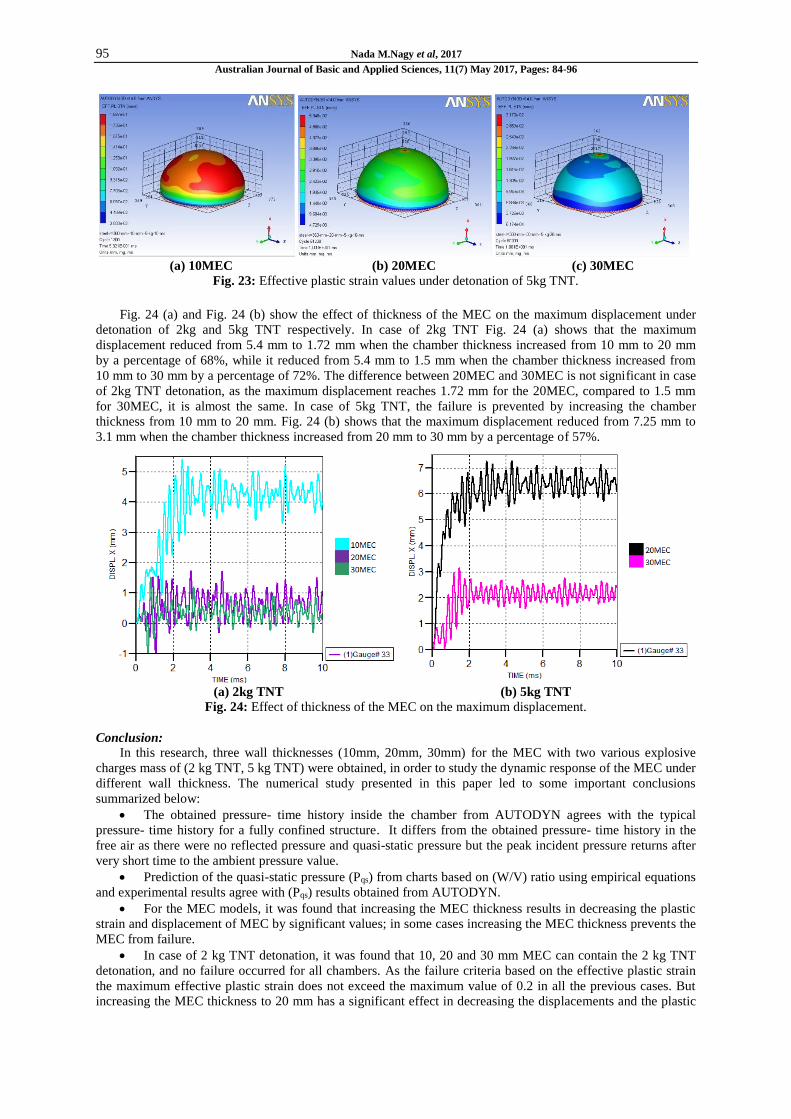
(a) 10MEC (b) 20MEC (c) 30MEC
Fig. 23: Effective plastic strain values under detonation of 5kg TNT.
Fig. 24 (a) and Fig. 24 (b) show the effect of thickness of the MEC on the maximum displacement under
detonation of 2kg and 5kg TNT respectively. In case of 2kg TNT Fig. 24 (a) shows that the maximum
displacement reduced from 5.4 mm to 1.72 mm when the chamber thickness increased from 10 mm to 20 mm
by a percentage of 68%, while it reduced from 5.4 mm to 1.5 mm when the chamber thickness increased from
10 mm to 30 mm by a percentage of 72%. The difference between 20MEC and 30MEC is not significant in case
of 2kg TNT detonation, as the maximum displacement reaches 1.72 mm for the 20MEC, compared to 1.5 mm
for 30MEC, it is almost the same. In case of 5kg TNT, the failure is prevented by increasing the chamber
thickness from 10 mm to 20 mm. Fig. 24 (b) shows that the maximum displacement reduced from 7.25 mm to
3.1 mm when the chamber thickness increased from 20 mm to 30 mm by a percentage of 57%.
(a) 2kg TNT (b) 5kg TNT
Fig. 24: Effect of thickness of the MEC on the maximum displacement.
Conclusion:
In this research, three wall thicknesses (10mm, 20mm, 30mm) for the MEC with two various explosive
charges mass of (2 kg TNT, 5 kg TNT) were obtained, in order to study the dynamic response of the MEC under
different wall thickness. The numerical study presented in this paper led to some important conclusions
summarized below:
The obtained pressure- time history inside the chamber from AUTODYN agrees with the typical
pressure- time history for a fully confined structure. It differs from the obtained pressure- time history in the
free air as there were no reflected pressure and quasi-static pressure but the peak incident pressure returns after
very short time to the ambient pressure value.
Prediction of the quasi-static pressure (Pqs) from charts based on (W/V) ratio using empirical equations
and experimental results agree with (Pqs) results obtained from AUTODYN.
For the MEC models, it was found that increasing the MEC thickness results in decreasing the plastic
strain and displacement of MEC by significant values; in some cases increasing the MEC thickness prevents the
MEC from failure.
In case of 2 kg TNT detonation, it was found that 10, 20 and 30 mm MEC can contain the 2 kg TNT
detonation, and no failure occurred for all chambers. As the failure criteria based on the effective plastic strain
the maximum effective plastic strain does not exceed the maximum value of 0.2 in all the previous cases. But
increasing the MEC thickness to 20 mm has a significant effect in decreasing the displacements and the plastic

96 Nada M.Nagy et al, 2017
Australian Journal of Basic and Applied Sciences, 11(7) May 2017, Pages: 84-96
strain values. Increasing the MEC thickness from 20 mm to 30 mm is not significant in case of 2 kg TNT
detonation, as the maximum displacement of the 30MEC is almost same as the maximum displacement of the
20MEC.
In case of 5 kg TNT detonation, the 10MEC could not contain the 5 kg TNT detonation. The 10MEC
reaches the maximum effective plastic strain value of 0.2 just after 0.58ms and then failure occurred. For
20MEC and 30MEC no failure occurred and they were able to contain the detonation, as the maximum effective
plastic strain does not exceed the maximum value of 0.2 for both cases. Increasing the MEC thickness from 20
mm to 30 mm in this case has more significant effect in decreasing the displacements and the plastic strain
values than the case of 2 kg TNT.
In case of the chamber failure (10MEC under 5 kg TNT detonation), it was found that the 10MEC
existence delays the arrival time of the shock wave and decays the peak incident pressure value by a significant
percentage. A comparison between both pressures and times in the free air and after the chamber failure was
done. The existence of the MEC decays the pressure value from 1450 kPa to 880 kpa by a percentage of 39%.
Finally, the maximum effective plastic strain does not exceed the maximum value in all cases except in
case of 5kg detonation using10MEC.10MEC was not able to contain the 5kg detonation, but it has a significant
contribution in decreasing the pressure values. 20MEC and 30MEC were able to contain both 2kg and 5kg
detonation with significantly small values of displacements and plastic strain. 20MEC yields to be the best
design for a mobile explosive chamber to contain small explosive charges up to 5kg, as its weight much lighter
than the 30MEC which make it easily transported compared to 30MEC.
The results of the numerical investigation showed that the MEC can contain the detonation of small charges
up to 5kg TNT. Field testing is recommended to verify the numerical results and to investigate the risks of MEC
installation process. Also, field testing using lager explosive charge masses is required to obtain the ultimate
strength of the designed MECs, and to determining their actual capacities. More research is required to study the
influence of represent the ground in the numerical analysis on the dynamic response of the MECs.
The main target of the MEC is to provide a total containment against explosion effects after the specialists
investigate any suspected item. The MEC protect the person who responsible for bomb disposal, as well as
ensures safely detonation for the surrounding area.
REFERENCES
Baker, W., 1983. Explosion HazardsandEvaluation, New York: ElsevierScientific PublishingCompany.
Beshara. FBA, 1994. "Modelling of blast loading on aboveground structures—II. Internal blast and ground
shock." Computers & structures, 51(5): 597-606.
Daily.mail., 2015. "Death of a hero live on their cell phones: Passersby casually film last moments of brave
bomb disposal officer, killed as he tried to defuse device left outside Cairo petrol station." Retrieved 3/1/2017,
from http://www.dailymail.co.uk/news/article-2899740/Death-hero-live-mobile-phones-Group-film-bomb-
disposal-officer-killed-tried-defuse-device-left-outside-Cairo-petrol-station.html.
Dialy.news.Egypt, 2016. "policemen-killed-car-bombing-giza." Retrieved 3/15/2017, from
www.dailynewsegypt.com/2016/12/09/6-policemen-killed-car-bombing-giza.
Elshafey, M.M., 2008. Experimental and Numerical Investigations for the Development of Safe
Transportation of Hazardous Materials, University of Ottawa.
Feldgun, V., Y. Karinski, I. Edri and D. Yankelevsky, 2016. "Prediction of the quasi-static pressure in
confined and partially confined explosions and its application to blast response simulation of flexible
structures." International Journal of Impact Engineering 90: 46-60.
Karlsson, D.D., 2013. VALIDATE SIMULATION TECHNIQUES OF A MOBILE EXPLOSIVE
CONTAINMENT VESSEL. 5th ANSA & μETA International Conference. Thessaloniki Greece: 9.
Ngo, T., P. Mendis, A. Gupta and J. Ramsay, 2007. "Blast loading and blast effects on structures–an
overview." Electronic Journal of Structural Engineering, 7: 76-91.
Remennikov, A.M., 2003. "A review of methods for predicting bomb blast effects on buildings." Journal of
battlefield technology, 6(3): 5.
Smith, P.D. and T.A. Rose, 2002. "Blast loading and building robustness." Progress in structural
engineering and materials, 4(2): 213-223.
Tavakoli, H. and F. Kiakojouri, 2014. "Numerical dynamic analysis of stiffened plates under blast loading."
Latin American Journal of Solids and Structures, 11(2): 185-199.
The.guardian, 2010. "German bomb squad team killed trying to defuse second world war device."
Retrieved 3/1/2017, 2017, from https://www.theguardian.com/world/2010/jun/02/germany-bomb-war-kills-
three.
Theory Manual for AUTODYN 2003, n.d. .