Ultralow–switching current density multilevel phase-change ...

Numerical 3D BEM simulation of the chromium layer thickness distribution on parts in a rack plating configuration
J. Deconinck1, G. Floridor1, B. Van den Bossche2, L. Bortels2 & G. Nelissen2
1Vrije Universiteit Brussel, Department of Electrical Engineering, Belgium 2ElSyCa N.V., Zellik, Belgium
Abstract
A three dimensional Boundary Element Method (BEM) approach is used to compute the current density and plated layer thickness distribution on parts of complex shape in a rack plating configuration. Results are shown for a decorative chromium plating process. Simulations take into account electrode polarisation characteristics and the plating efficiency. The entire plating tank configuration is considered, including dimensions and position of anode baskets or rods, the number of parts on the rack, and the position of the rack in the tank. For decorative chromium plating, simulated results reveal that parts located at the outer positions of the rack receive a current that might double the value received by a central part, hence also the average plated thickness from one part to another might differ by a factor 2. The variation of the plated thickness on a single part is up to a factor 5 or more, with some of the inner zones receiving no layer thickness at all. These results are in agreement with industrial experience. The BEM solver is integrated in the SolidWorks CAD environment, enabling a fast modification of the dimensions of the entire configuration (rack configuration, current thieves, etc.), the surface mesh characteristics (determining the computational accuracy), and the physico-chemical input parameters (polarisation and efficiency characteristics, electrolyte conductivity, imposed DC or bipolar currents, etc.). Keywords: electrodeposition, plating, advanced software packages, BEM.
© 2005 WIT Press WIT Transactions on Engineering Sciences, Vol 48, www.witpress.com, ISSN 1743-3533 (on-line)
Simulation of Electrochemical Processes 173

1 Introduction
Although advanced numerical methods exist and have been applied with great success in a broad range of engineering domains (hydrodynamics, aerodynamics, structural mechanics, heat transfer, etc…), the use of these methods for electrochemical plating applications remains rather limited. One of the main reasons is the complexity of the physical, chemical and electrical phenomena governing electrochemical reactor behavior. In general, a complex interplay of the following phenomena takes place: electrochemical electrode kinetics, electrolyte hydrodynamics, ionic mass transport, gas evolution, and heat generation in the bulk and at the electrode-electrolyte interfaces. From an engineering point of view however, the main focus is on the current density and layer thickness distribution, which principally depend upon the following phenomena:
• ohmic drop in the electrolyte solution; • cathodic polarization and plating efficiency; • anodic polarization; • plating tank configuration including anode positioning, screens and current
thieves; • work piece shape and dimensions; • selective insulation of work piece surfaces; • number and position of work pieces on a rack; • total current injected and anode and work piece contacting method.
The simplest modeling approach that takes into account these phenomena is commonly denoted as the ‘potential model’[1]. In order to produce reliable simulation results, the physico-chemical input parameters (polarization behavior, plating efficiency and electrolyte conductivity) need to be defined carefully for the electrolyte bath being used, at a given operating temperature. In this work, the ElSyCa PlatingMaster v1.0 software tool [2] is used to design a dedicated reactor for the selective chromium plating of an oil pump shaft. The current density and layer thickness distribution are evaluated for each step in the reactor design process. In a first step, the work piece is partly insulated (taped), in order to redirect the current to the surfaces that will be subject to wear and corrosion in practical mechanical operation conditions of the pump. A tubular reactor with cylindrical anode mesh is used. In the next steps, the anodes are redesigned, abandoning the concept of a single far away anode mesh for multiple anode meshes closer to the targeted surfaces (though still connected to one single current source). The anode positions and dimensions are optimized until a layer thickness distribution is obtained meeting certain minimum and maximum specifications. Plating within these product specifications avoids performing (expensive) additional grinding operations. The ElSyCa PlatingMaster tool is entirely integrated in the SolidWorks® CAD environment hence enabling a very fast adaptation of the reactor design at each step. The unique combination of a user-friendly and powerful CAD tool with a fast and accurate current density and layer thickness distribution simulation tool allows to design and optimize the entire reactor within a couple
© 2005 WIT Press WIT Transactions on Engineering Sciences, Vol 48, www.witpress.com, ISSN 1743-3533 (on-line)
174 Simulation of Electrochemical Processes

of hours. The ElSyCa PlatingMaster tool can also be used for the evaluation of current density and layer thickness distributions on electrodes with high internal resistivity e.g. wafers3, or for electrochemical machining applications [4,5].
2 Mathematical model and solution method
A brief overview of the mathematical model behind the current density and layer thickness distribution simulations is given below [1]. Although cathodic deposition reaction mechanisms can become very complex, the polarisation behaviour for single metal deposition processes
Me ze Me z →++ - is often quite accurately described by a Butler-Volmer type
relation:
( ))UV(RT/F)UV(RT/F0n
ca eejj −−− −⋅= αα
(1)
where jn is the amplitude of current density normal to the electrode surface, jo is the exchange current density, R the gas constant, T the temperature, αa and αc the anodic and cathodic charge transfer coefficients, and E01 the equilibrium potential for the deposition reaction. V and U hold for the electrode respectively electrolyte potential. The main reaction occurring at inert impressed current anodes is oxygen evolution. Due to the thin passivation layer that is often present on the surface of this type of electrodes, a linear relation can describe the polarisation behavior:
B)UV(Ajn +−= (2)
with A and B polarisation constants. This approach is sufficiently accurate. The ohmic drop effects in the electrolyte are described by the Laplace equation for the electrolyte potential U:
Uσ j )j( 0 ∇−==∇ (3)
On insulating boundaries, the current density perpendicular to the surface should be zero, which results in the following boundary condition:
.01.Uj1.j nnn =∇−== σ (4)
On electrodes, jn is given by equations of type (1) or (2). The local metal thickness ∆d on the cathode is simply computed from Faraday’s law:
ρ z Ft jM
d n∆θ∆ =
(5) where θ is the efficiency for the deposition process (depending on the current density jn). M holds for the atomic weight of the metal, ρ for the density, z is the
© 2005 WIT Press WIT Transactions on Engineering Sciences, Vol 48, www.witpress.com, ISSN 1743-3533 (on-line)
Simulation of Electrochemical Processes 175

number of electrons exchanged in the metal deposition reaction, and F is Faraday’s constant. The physico-chemical input data (polarisation behavior, plating efficiency and electrolyte conductivity) as used in this paper are those for a typical industrial hexavalent Cr bath.
2.1 Numerical solution method
As the conductivity of the computational domain is constant, BEM is to be preferred over other discretisation methods as Finite Element (FEM), Finite Volume (FVM) and Finite Difference Methods (FDM), to solve the simplified charge conservation equation (5). When the BEM is applied, only the boundaries of the domain are to be discretised. Another advantage, particularly for electrochemical systems, is that the current density distribution along the electrodes is a direct unknown to this problem, rather than a variable that has to be computed afterwards from the derivative of the potential field perpendicularly to the electrodes. This turns BEM into a more accurate method for potential problems, compared to FEM, FVM and FDM. The characteristic BEM equation for the contribution to node i is [7]:
∫∫ =∂∂
+ΓΓ
ΓΓ dQ*wdn*wUUc ii (6)
with
rw
π=
41* (7)
the 3D Green function ( r representing the position vector) and nUQ∂∂
= the
flux at the boundary nodes. ci is the space angle in node i. Γ is the 2D surface that encloses the 3D computational domain. In order to apply BEM, the boundary Γ is to be discretised into a series of N non-overlapping elements, transforming equation (7) into:
∑ ∫∑ ∫==
=∂∂
+N
1j
N
1j
ii
jj
dQ*wdn*wUUc
ΓΓ
ΓΓ (8)
The index j ranges over all elements of the domain and integration is performed over the surface Γj of each element. Triangular elements with linear shape functions for the unknown potential U and current density Q are used for the 3D BEM computations as presented in this paper, restricting the unknowns to the N nodal values. Taking into account equation (7), the BEM system of equations can be expressed in matrix form:
{ } { }nJ]G[U]H[ ⋅=⋅ (9)
© 2005 WIT Press WIT Transactions on Engineering Sciences, Vol 48, www.witpress.com, ISSN 1743-3533 (on-line)
176 Simulation of Electrochemical Processes
with { }U and { }nJ unknown vectors of size N. Once the boundary conditions have been introduced, i.e. zero current on insulators and overpotential relation (2) on electrodes, the system takes the form:
{ }
=−=
⋅=⋅0J
)UV(fJ]G[U]H[
n
n (10)
The matrices H and G in equation (10) are fully populated and depend only on the geometry of the system and the conductivity of the domain. This system of equations can be rewritten to group all unknowns in the left hand side vector:
( )
−⋅=
⋅
0jV
]G[UJ
]H[ n*n* η (11)
In most practical cases, system (11) is non-linear, except when η(jn) is linear in jn. The non-linear system equation matrix is solved using a Newton-Raphson iterative method, combined with a standard Gauss algorithm to tackle the linear system of equations that appears after each iteration of the Newton-Raphson procedure. The electrode polarization data can be specified either as a linear or an exponential (Butler-Volmer) expression. Also a numerical data set can be used, in this case the data couples (V-U,jn) are transferred into a continuous derivable curve using a spline polynomial function. An automated grid generator is used to produce the surface mesh that is required for the BEM computations7. This flexible grid generator creates an unstructured or structured mesh for each surface separately, or an unstructured mesh with structured boundary zones. The construction of a mesh that is optimally refined towards zones where edge effects are expected, and that generates coarse elements at any other position, allows to produce reliable numerical results with a restricted number of elements, hence limiting the computational efforts to solve the system of equations to a minimum.
3 Application
3.1 Configuration
The configuration consists of a brick shaped plating tank containing a rack with 20 parts (covers of an oil pump) as shown in figure 1. The anodes baskets (not shown) are positioned on the front plane. The biggest challenge in rack plating is ensuring uniform plating over the entire rack. Due to the edge effects, the parts located on the outside of the rack attract more current. This is further complicated by the fact that in most applications, the parts are placed manually on the fixtures, thus leading to sometimes badly positioned parts on the rack. To simulate the influence of the placement on the current density and deposit distribution, one of the parts is protruding (closer to the anodes) the plane of the
© 2005 WIT Press WIT Transactions on Engineering Sciences, Vol 48, www.witpress.com, ISSN 1743-3533 (on-line)
Simulation of Electrochemical Processes 177

other parts and one part is positioned further away from the anodes. Because the potential model assumes the mass transport to be ideal, the flow of the electrolyte does not need to be determined. The entire configuration was defined in the SolidWorks© CAD package, and simulations were performed with the ElSyCa PlatingMaster© v1.0 software tool, which is entirely integrated in this CAD package2.
Figure 1: Configuration of 20 parts on a rack, with the red part (2, 2) protruding and the blue part (3, 4) moved to the back.
3.2 Boundary conditions
A total current of 700 A is imposed on the anode baskets, leading to a mean current of 35 A per part. In its turn, this gives an average current density of about 5000 A/m2 on the parts. The total plating time is set to 10 minutes.
3.3 Surface mesh
A rather fine triangular non-uniform surface mesh is used for the tank oil pump as shown in figure 2. The outer walls of the plating tank and the anodes (not shown) are discretized using larger triangular elements. This ensures an optimal trade off between computational efforts and accuracy of the simulated results.
© 2005 WIT Press WIT Transactions on Engineering Sciences, Vol 48, www.witpress.com, ISSN 1743-3533 (on-line)
178 Simulation of Electrochemical Processes

Figure 2: Triangular surface mesh for the oil pumps.
3.4 Computational specifications
The total number of elements used to solve the BEM problem is 57196 triangles and 38452 points. The CPU time is about 30 minutes on a 1400 MHz Pentium IV PC for 7 iterations in the Newton-Raphson procedure, after which a sufficient convergence level of 1E-5 is reached.
3.5 Results and discussion
Figure 3 shows the resulting deposit thickness (in µm) distribution over the entire rack. As expected the parts on the outer side of the rack receive a higher current density. As seen in figure 3, these edge effects can easily lead to a deposit for a part positioned towards the outer rim of the rack (10 µm or higher) that is double the deposit of a part in the middle of the rack (about 5 µm). Also the part positioned closer to the anodes has a higher deposit. On the other hand, the part placed further away from the anode does not get plated at all. From this one can conclude that an accurate positioning of the part on the fixtures is a very critical issue when trying to achieve uniform chromium plating thickness in rack plating applications.
© 2005 WIT Press WIT Transactions on Engineering Sciences, Vol 48, www.witpress.com, ISSN 1743-3533 (on-line)
Simulation of Electrochemical Processes 179
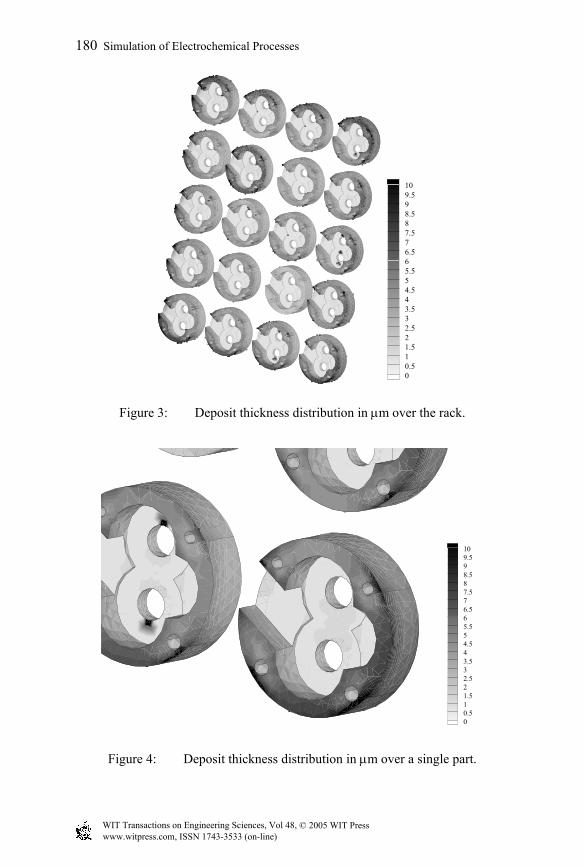
109.598.587.576.565.554.543.532.521.510.50
Figure 3: Deposit thickness distribution in µm over the rack.
109.598.587.576.565.554.543.532.521.510.50
Figure 4: Deposit thickness distribution in µm over a single part.
© 2005 WIT Press WIT Transactions on Engineering Sciences, Vol 48, www.witpress.com, ISSN 1743-3533 (on-line)
180 Simulation of Electrochemical Processes
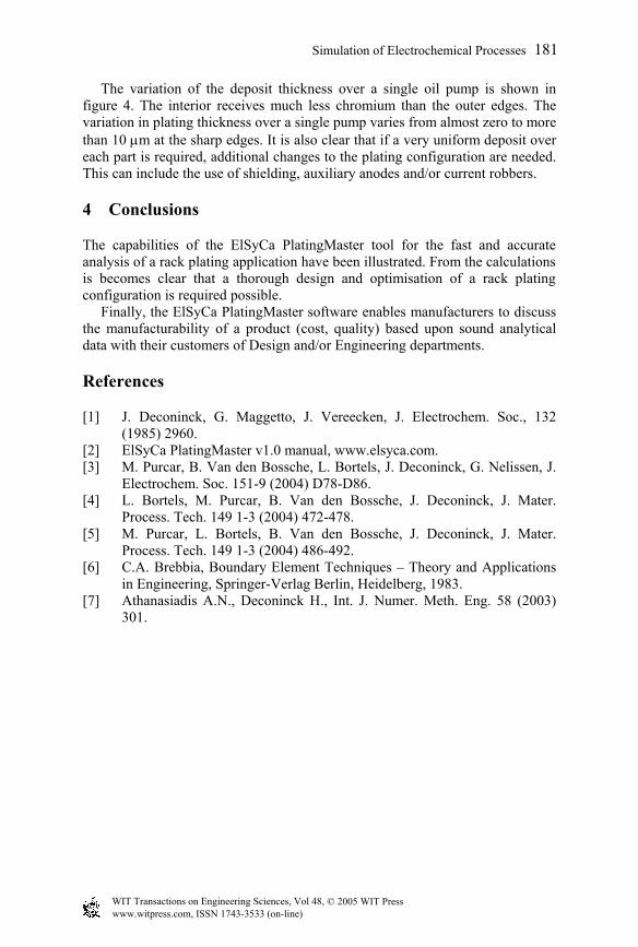
The variation of the deposit thickness over a single oil pump is shown in figure 4. The interior receives much less chromium than the outer edges. The variation in plating thickness over a single pump varies from almost zero to more than 10 µm at the sharp edges. It is also clear that if a very uniform deposit over each part is required, additional changes to the plating configuration are needed. This can include the use of shielding, auxiliary anodes and/or current robbers.
4 Conclusions
The capabilities of the ElSyCa PlatingMaster tool for the fast and accurate analysis of a rack plating application have been illustrated. From the calculations is becomes clear that a thorough design and optimisation of a rack plating configuration is required possible. Finally, the ElSyCa PlatingMaster software enables manufacturers to discuss the manufacturability of a product (cost, quality) based upon sound analytical data with their customers of Design and/or Engineering departments.
References
[1] J. Deconinck, G. Maggetto, J. Vereecken, J. Electrochem. Soc., 132 (1985) 2960.
[2] ElSyCa PlatingMaster v1.0 manual, www.elsyca.com. [3] M. Purcar, B. Van den Bossche, L. Bortels, J. Deconinck, G. Nelissen, J.
Electrochem. Soc. 151-9 (2004) D78-D86. [4] L. Bortels, M. Purcar, B. Van den Bossche, J. Deconinck, J. Mater.
Process. Tech. 149 1-3 (2004) 472-478. [5] M. Purcar, L. Bortels, B. Van den Bossche, J. Deconinck, J. Mater.
Process. Tech. 149 1-3 (2004) 486-492. [6] C.A. Brebbia, Boundary Element Techniques – Theory and Applications
in Engineering, Springer-Verlag Berlin, Heidelberg, 1983. [7] Athanasiadis A.N., Deconinck H., Int. J. Numer. Meth. Eng. 58 (2003)
301.
© 2005 WIT Press WIT Transactions on Engineering Sciences, Vol 48, www.witpress.com, ISSN 1743-3533 (on-line)
Simulation of Electrochemical Processes 181