Number: 124 - IAPMO · 2019-07-19 · S/BA series hangers areused to support a CFS joist. The...
29
Number: 124 Originally Issued: 06/25/2010 Revised: 07/19/2019 Valid Through: 06/30/2020 The product described in this Uniform Evaluation Service (UES) Report has been evaluated as an alternative material, design or method of construction in order to satisfy and comply with the intent of the provision of the code, as noted in this report, and for at least equivalence to that prescribed in the code in quality, strength, effectiveness, fire resistance, durability and safely, as applicable, in accordance with IBC Section 104.11. This document shall only be reproduced in its entirety. Copyright © 2019 by International Association of Plumbing and Mechanical Officials. All rights reserved. Printed in the United States. Ph: 1-877-4IESRPT • Fax: 909.472.4171 web: www.uniform-es.org • 4755 East Philadelphia Street, Ontario, California 91761-2816 – USA Page 1 of 29 Simpson Strong-Tie Company Inc. 5956 West Las Positas Boulevard Pleasanton, California 94588 (800) 999-5099 www.strongtie.com SIMPSON STRONG-TIE CONNECTORS FOR COLD-FORMED STEEL CONSTRUCTION CSI Division: 05—METALS CSI Section: 05 05 23—Metal Fastenings 1.0 SCOPE OF EVALUATION 1.1 Compliance to the following codes & regulations: • 2018, 2015, 2012, 2009, and 2006 International Building Code ® (IBC) • 2018, 2015, 2012, 2009, and 2006 International Residential Code ® (IRC) • 2017 City of Los Angeles Building Code (LABC) - attached Supplement • 2017 City of Los Angeles Residential Code (LARC ) -attached Supplement 1.2 Evaluated in accordance with: • ICC-ES AC261, Acceptance Criteria for Connectors Used With Cold-Formed Steel Structural Members, approved October 2011, editorially revised August 2018. 1.3 Properties assessed: • Structural 1.4 Reference Standards The term AISI Specification used throughout this report refers to the reference standard for the applicable building code as follows: • 2006 IBC – North American Specification for the Design of Cold-Formed Steel Structural Members, including 2004 Supplement (NAS-01) • 2009 IBC – North American Specification for the Design of Cold-Formed Steel Structural Members (S100-07) • 2012 IBC – North American Specification for the Design of Cold-Formed Steel Structural Members, with Supplement 2 (S100-07/S2-10) • 2015 IBC – North American Specification for the Design of Cold-Formed Steel Structural Members (S100-12) • 2018 IBC – North American Specification for the Design of Cold-Formed Steel Structural Members with Supplement 1 (S100-16w/S1-18) 2.0 PRODUCT USE Simpson Strong-Tie Connectors for Cold-Formed Steel (CFS) Construction may be used as CFS framing connectors in accordance with IBC Section 104.11, Section 2211.1 of the 2018, 2015, and 2012 IBC, and Section 2210.1 of the 2009 and 2006 IBC. Hold-down, hurricane tie, and bracing products in this report may also be used in structures regulated under the IRC when the tabulated strength capacity exceeds that prescribed by the IRC or when an engineered design is submitted in accordance with Section R301.1.3 of the IRC. 3.0 PRODUCT DESCRIPTION 3.1 Product information 3.1.1 S/HDS and S/HDB Hold-downs: S/HD series hold- downs are used to anchor CFS or structural steel member(s) to foundations or to connect upper story to lower story CFS or structural steel member(s) (floor-to-floor ties). They are also used for anchoring concrete and masonry walls to CFS or structural steel member(s) to provide lateral support for the walls in accordance with IBC Sections 1604.8.1 and 1604.8.2. When regulated under the IRC, the hold-down connectors may also be used when their tabulated Allowable Strength Design (ASD) load exceeds that required by 2018, 2015, 2012, and 2009 IRC Section R603.9.4.2 (2006 IRC Section R603.7.2) or when an engineered design is submitted in accordance with Section R301.1.3 of the IRC. S/HDS series hold-downs use self-tapping screws to attach to the CFS or structural steel member(s). S/HDB series hold- downs use bolts to attach to the CFS or structural steel member(s). A round steel standard plate (W) washer conforming to ASME B18.22.1, Type A, shall be installed between the bolt nut and the framing member. Hold-down bodies for S/HD8S, S/HD10S, S/HD8B and S/HD10B are cold-formed from No. 10 gage steel. S/HD15S and S/HD15B bodies are cold-formed from No. 7 gage steel. Base plates for all models are fabricated from 1 /2 inch (12.7 mm) thick steel. Figure 1, Table 1A and Table 1B of this report provide dimensions, required fasteners, and Allowable Strength Design (ASD) and Load and Resistance Factor Design (LRFD) loads. 3.1.2 S/HDU Hold-downs: S/HDU series hold-downs are used to anchor CFS or structural steel member(s) to foundations or to connect upper story to lower story CFS or structural steel member(s) (floor-to-floor ties). The connectors also are used for anchoring concrete and masonry walls to CFS or structural steel member(s) to provide lateral support for the walls in accordance with IBC Sections 1604.8.1 and 1604.8.2.
Transcript of Number: 124 - IAPMO · 2019-07-19 · S/BA series hangers areused to support a CFS joist. The...

Number: 124
Originally Issued: 06/25/2010 Revised: 07/19/2019 Valid Through: 06/30/2020
The product described in this Uniform Evaluation Service (UES) Report has been evaluated as an alternative material, design or method of construction in order to satisfy and comply with the intent of the provision of the code, as noted in this report, and for at least equivalence to that prescribed in the code in quality, strength, effectiveness, fire resistance, durability and safely, as applicable, in accordance with IBC Section 104.11. This document shall only be reproduced in its entirety.
Copyright © 2019 by International Association of Plumbing and Mechanical Officials. All rights reserved. Printed in the United States. Ph: 1-877-4IESRPT • Fax: 909.472.4171 web: www.uniform-es.org • 4755 East Philadelphia Street, Ontario, California 91761-2816 – USA Page 1 of 29
Simpson Strong-Tie Company Inc. 5956 West Las Positas Boulevard Pleasanton, California 94588 (800) 999-5099 www.strongtie.com SIMPSON STRONG-TIE CONNECTORS FOR COLD-FORMED STEEL CONSTRUCTION CSI Division: 05—METALS CSI Section: 05 05 23—Metal Fastenings 1.0 SCOPE OF EVALUATION 1.1 Compliance to the following codes & regulations: • 2018, 2015, 2012, 2009, and 2006 International Building
Code® (IBC) • 2018, 2015, 2012, 2009, and 2006 International Residential
Code® (IRC) • 2017 City of Los Angeles Building Code (LABC) -
attached Supplement • 2017 City of Los Angeles Residential Code
(LARC ) -attached Supplement 1.2 Evaluated in accordance with: • ICC-ES AC261, Acceptance Criteria for Connectors Used
With Cold-Formed Steel Structural Members, approved October 2011, editorially revised August 2018.
1.3 Properties assessed:
• Structural
1.4 Reference Standards The term AISI Specification used throughout this report refers to the reference standard for the applicable building code as follows: • 2006 IBC – North American Specification for the Design
of Cold-Formed Steel Structural Members, including 2004 Supplement (NAS-01)
• 2009 IBC – North American Specification for the Design of Cold-Formed Steel Structural Members (S100-07)
• 2012 IBC – North American Specification for the Design of Cold-Formed Steel Structural Members, with Supplement 2 (S100-07/S2-10)
• 2015 IBC – North American Specification for the Design of Cold-Formed Steel Structural Members (S100-12)
• 2018 IBC – North American Specification for the Design of Cold-Formed Steel Structural Members with Supplement 1 (S100-16w/S1-18)
2.0 PRODUCT USE Simpson Strong-Tie Connectors for Cold-Formed Steel (CFS) Construction may be used as CFS framing connectors in accordance with IBC Section 104.11, Section 2211.1 of the 2018, 2015, and 2012 IBC, and Section 2210.1 of the 2009 and 2006 IBC. Hold-down, hurricane tie, and bracing products in this report may also be used in structures regulated under the IRC when the tabulated strength capacity exceeds that prescribed by the IRC or when an engineered design is submitted in accordance with Section R301.1.3 of the IRC. 3.0 PRODUCT DESCRIPTION 3.1 Product information 3.1.1 S/HDS and S/HDB Hold-downs: S/HD series hold-downs are used to anchor CFS or structural steel member(s) to foundations or to connect upper story to lower story CFS or structural steel member(s) (floor-to-floor ties). They are also used for anchoring concrete and masonry walls to CFS or structural steel member(s) to provide lateral support for the walls in accordance with IBC Sections 1604.8.1 and 1604.8.2. When regulated under the IRC, the hold-down connectors may also be used when their tabulated Allowable Strength Design (ASD) load exceeds that required by 2018, 2015, 2012, and 2009 IRC Section R603.9.4.2 (2006 IRC Section R603.7.2) or when an engineered design is submitted in accordance with Section R301.1.3 of the IRC. S/HDS series hold-downs use self-tapping screws to attach to the CFS or structural steel member(s). S/HDB series hold-downs use bolts to attach to the CFS or structural steel member(s). A round steel standard plate (W) washer conforming to ASME B18.22.1, Type A, shall be installed between the bolt nut and the framing member. Hold-down bodies for S/HD8S, S/HD10S, S/HD8B and S/HD10B are cold-formed from No. 10 gage steel. S/HD15S and S/HD15B bodies are cold-formed from No. 7 gage steel. Base plates for all models are fabricated from 1/2 inch (12.7 mm) thick steel. Figure 1, Table 1A and Table 1B of this report provide dimensions, required fasteners, and Allowable Strength Design (ASD) and Load and Resistance Factor Design (LRFD) loads. 3.1.2 S/HDU Hold-downs: S/HDU series hold-downs are used to anchor CFS or structural steel member(s) to foundations or to connect upper story to lower story CFS or structural steel member(s) (floor-to-floor ties). The connectors also are used for anchoring concrete and masonry walls to CFS or structural steel member(s) to provide lateral support for the walls in accordance with IBC Sections 1604.8.1 and 1604.8.2.

Number: 124
Originally Issued: 06/25/2010 Revised: 07/19/2019 Valid Through: 06/30/2020
Page 2 of 29
When regulated under the IRC, the hold-down connectors may also be used when their tabulated ASD load exceeds that required by 2018, 2015, 2012, and 2009 IRC Section R603.9.4.2 (2006 IRC Section R603.7.2) or when an engineered design is submitted in accordance with Section R301.1.3 of the IRC. S/HDU hold-downs consist of pre-deflected bodies formed from No. 10 gage galvanized steel, and a base washer fabricated from No. 3 gage steel. S/HDU series hold-downs use self-tapping screws to attach to the CFS or structural steel member(s). Figure 2 and Table 2 of this report provide dimensions, required fasteners, and ASD and LRFD loads. 3.1.3 S/LTT Light Tension Ties: S/LTT series light tension ties are used to anchor CFS member(s) to foundations or to connect upper story to lower story CFS member(s) (floor-to-floor ties). The connectors are also used for anchoring concrete and masonry walls to CFS member(s) to provide lateral support for the walls in accordance with IBC Section 1604.8. S/LTT light tension ties consist of a steel strap component with a 90 degree angle bend at the end and a base plate component installed in the bend. The body of the S/LTT20 is formed from No.12 gage galvanized steel. Base plate component for S/LTT’s is No. 3 gage galvanized steel. Figure 3 and Table 3 of this report provide product dimensions, required fasteners, and ASD and LRFD loads. 3.1.4 S/DTT2Z Deck Tension Ties: S/DTT2Z deck tension ties are used to anchor CFS member(s) to foundations or to connect upper story to lower story CFS member(s) (floor-to-floor ties). The connectors are also used for anchoring concrete and masonry walls to CFS member(s) to provide lateral support for the walls in accordance with IBC Section 1604.8. The S/DTT2Z tension tie is formed from a single-piece of structural steel with pre-punched holes for installation of self-tapping screws used to connect the S/DTT2Z to CFS member(s). The embossed seat element reduces seat deformation. The S/DTT2Z is die-formed from No. 14 gage galvanized steel. A ½ inch (12.7 mm) diameter (1⅜ inch (34.9 mm) OD) standard cut washer is included with the S/DTT2Z and is required between the nut and the seat. Figure 3 and Table 3 of this report provide product dimensions, required fasteners, and ASD and LRFD loads. 3.1.5 S/HTT and HTT Heavy Tension Ties: S/HTT and HTT series heavy tension ties are used to anchor CFS member(s) to foundations or to connect upper story to lower story CFS member(s) (floor-to-floor ties). The connectors are also used as anchorage of concrete and masonry walls to CFS member(s) to provide lateral support for the walls in accordance with IBC Section 1604.8. S/HTT and HTT heavy tension ties are formed from a single piece of steel and consist of a steel strap with a four-ply
formed seat element as an anchor bolt attachment. The straight strap portion has pre-punched holes for installation of self-tapping screws used to connect the S/HTT and HTT to CFS member(s). S/HTT and HTT are die-formed from No. 11 gage galvanized steel. Figure 3 and Table 3 of this report provide product dimensions, required fasteners and ASD and LRFD loads. 3.1.6 S/BA Joist Hangers: S/BA series hangers are used to support a CFS joist. The hangers are die-formed from No. 14 gage galvanized steel. The hanger shall be attached onto CFS header sections using self-tapping screws. Alternatively, the hanger shall be attached by welding each top flange to the supporting member. Figure 4 and Table 4 of this report provide dimensions, required fasteners, and ASD (allowable)loads. 3.1.7 S/B & S/LBV Joist Hangers: S/B and S/LBV series hangers may be used to support CFS joists. The hangers are formed from No. 12 gage and No. 14 gage galvanized steel for S/B and S/LBV, respectively. The hanger shall be attached onto a CFS supporting member using self-tapping screws or may have each top flange welded to the supporting member. Figure 5 and Table 5 of this report provide dimensions, required fasteners, and ASD (allowable) loads. 3.1.8 S/JCT & S/HJCT Joist Hangers: S/JCT and S/HJCT hangers are used to support CFS joists. The S/JCT and S/HJCT hangers are formed from No. 14 gage and No. 12 gage galvanized steel, respectively. The hanger shall be attached onto CFS supporting member either by using self-tapping screws or by welding each top flange to the supporting member. The vertical flange of the hanger shall be fastened to the web of the joist using self-tapping screws. Alternatively, the hangers may be installed onto a supporting wood member with nails for S/JCT model series and with Simpson Strong-Tie SDS screws for the S/HJCT model series. Figure 6 and Table 6 of this report provide dimensions, required fasteners, and ASD (allowable)loads. 3.1.9 TJC37 Truss Jack Connector: TJC37 truss jack connector are used for skewed members or to connect jack trusses to girder trusses. TJC37 is formed from No. 16 gage galvanized steel and may be skewed from 0 degrees (perpendicular to the supporting member) to 67.5 degrees from the line perpendicular to the supporting member. When installing, the jack truss shall be positioned on the inside bend line with the end of the jack truss flush with the bend line. Then bend the TJC37 to the desired position. Figure 7 and Table 7 of this report provide dimensions, required fasteners, and ASD (allowable)loads. 3.1.10 TBD Truss Brace Diagonal: TBD22 truss brace diagonal may be used to comply with the temporary truss bracing recommendations in SBCA Cold-Formed Steel Building Component Safety Information book. The brace is a flat strap that is formed into an A-shape as it is pulled from the carton to provide rigidity and to prevent it sagging between the CFS trusses it braces during construction. The

Number: 124
Originally Issued: 06/25/2010 Revised: 07/19/2019 Valid Through: 06/30/2020
Page 3 of 29
TBD is formed from No. 22 gage galvanized steel. Figure 8 and Table 8 of this report provide dimensions, required fasteners, and ASD (allowable)loads. 3.1.11 S/H1A Hurricane Tie: S/H1A hurricane tie is used to tie a CFS rafter or truss chord to a CFS top track and wall stud. The hurricane tie is formed from No. 18 gage galvanized steel. Figure 9 and Table 9 of this report provide dimensions, required fasteners, and ASD (allowable)loads. 3.1.12 LSTA & MSTA Strap Ties: LSTA and MSTA strap ties are used to provide a tension connection between two CFS members. The ties are from 9 to 36 inches (228.6 to 914.4 mm) long and are 1¼ inches (31.2 mm) wide. Each strap has one row of staggered pre-punched holes. The straps are manufactured from various gages of galvanized steel. ASD (allowable) loads, fastener requirements, and steel thicknesses are shown in Table 10 of this report. Figure 10 of this report provides further information. 3.1.13 MSTC Strap Ties: MSTC strap ties are used to provide a tension connection between two CFS members. The ties are from 28¼ to 77¾ (717.6 to 1974.6 mm) inches long and are 3 inches (76.2 mm) wide. The straps have two rows of staggered pre-punched holes. They have countersunk fastener slots for a lower fastening profile, and coined edges for safer handling. The straps are manufactured from No. 16 gage and No. 14 gage of galvanized steel. ASD (allowable)loads, fastener requirements, and steel thicknesses are shown in Table 10 of this report. Figure 10 of this report provide further information. 3.1.14 S/MST Strap Ties: S/MST strap ties are used to provide a tension connection between two CFS members. They are from 27 to 72 inches (685.8 mm to 1829 mm) long and are 2-1/16 inches (52.4 mm) wide. Each strap has two rows pre-punched holes. The straps are manufactured from No. 12 gage and No. 10 gage of galvanized steel. ASD (allowable)loads, fastener requirements, and steel thicknesses are shown in Table 10 of this report. Figure 10 of this report provides further information. 3.1.15 LSTI & MSTI Strap Ties: LSTI and MSTI strap ties are used to provide a tension connection between two CFS members. The LSTI strap ties are either 49 or 73 inches (1245 or 1854 mm) long and MSTI strap ties are from 26 to 72 inches (660.4 to 1829 mm) long. The LSTI models are 3¾ inches (95.3 mm) wide and the MSTI models are 2-1/16 inches (52.4 mm) wide. The LSTI and MSTI straps are manufactured from No. 18 gage and No. 12 gage galvanized steel, respectively. ASD (allowable)loads, fastener requirements, and steel thicknesses are shown in Table 10 of this report. Figure 10 of this report provides further information. 3.1.16 ST Strap Ties: ST strap ties are used to provide a tension connection between two CFS members. The ties are manufactured in various widths and lengths. The straps are manufactured from various gages of galvanized steel. ASD
(allowable) loads, fastener requirements, and steel thicknesses are shown in Table 10 of this report. Figure 10 of this report provides further information. 3.1.17 FHA Strap Ties: FHA strap ties are used to provide a tension connection between two CFS members. The ties have a corrugated shape with a total width of 1-7/16 inches (36.5 mm). The straps are manufactured from No. 12 gage galvanized steel. ASD (allowable)loads, fastener requirements, and steel thicknesses are shown in Table 10 of this report. Figure 10 of this report provides further information. 3.1.18 HRS Heavy Strap Ties: HRS strap ties are used to provide a tension connection between two CFS members. They are 1-3/8 inches (34.9 mm) wide. The straps are manufactured from No. 12 gage galvanized steel. ASD (allowable) loads, fastener requirements, and steel thicknesses are shown in Table 10 of this report. Figure 10 of this report provides further information. 3.1.19 CS, CMST, & CMSTC Coiled Strap Ties: CS, CMST and CMSTC Coil strap ties are used to provide a tension connection between two CFS members. The ties are packaged in a coil so that the length of strap needed can be cut from the coil. The CS straps are 1-¼ inches (31.8 mm) wide. The CMST and CMSTC straps are 3 inches (76.2 mm) wide. The CMSTC has coined edges for safer handling. The straps are manufactured from various gages of galvanized steel. ASD (allowable)loads, fastener requirements, and steel thicknesses are shown in Table 11 of this report. Figure 11 of this report provides further information. 3.1.20 LTS, MTS, MTSC, HTS, & HTSC Twist Straps: LTS, MTS, MTSC, HTS, & HTSC Twist Straps ties may be used to provide a tension connection between two CFS members. LTS light twist Strap, MTS medium twist strap, and HTS heavy twist straps have a formed bend so that the ends are oriented 90 degrees from each other. The straps are 1¼ inches (31.8 mm) wide and the twist is located in the center of the strap, with the exception of the 30 inch (762 mm) long models. The twist straps are manufactured from various gages of galvanized steel. ASD (allowable)loads, fastener requirements, and steel thicknesses are shown in Table 12 of this report. Figure 12 of this report provides further information. 3.1.21 SP4 & SP6 Stud to Track Ties: The SP stud to track ties may be used to connect wall tracks to studs. The ties are formed from No. 20 gage galvanized steel. Figure 13 and Table 13 of this report provide dimensions, required fasteners, and ASD (allowable) loads. 3.1.22 SSP & DSP Stud to Track Ties: SSP and DSP stud to track ties may be used to connect wall tracks to studs. The SSP is 1⅜ inches (34.9 mm) wide for fastening to a single stud, while the DSP is 2¾ inches (69.9 mm) wide for fastening to double studs. The SSP and DSP are formed from No. 18 gage galvanized steel. Figure 14 and Table 14 of this
Number: 124
Originally Issued: 06/25/2010 Revised: 07/19/2019 Valid Through: 06/30/2020
Page 4 of 29
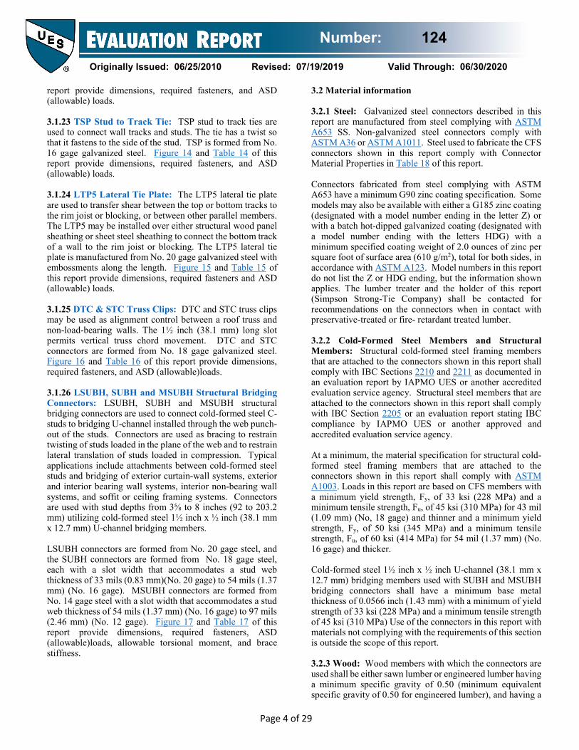
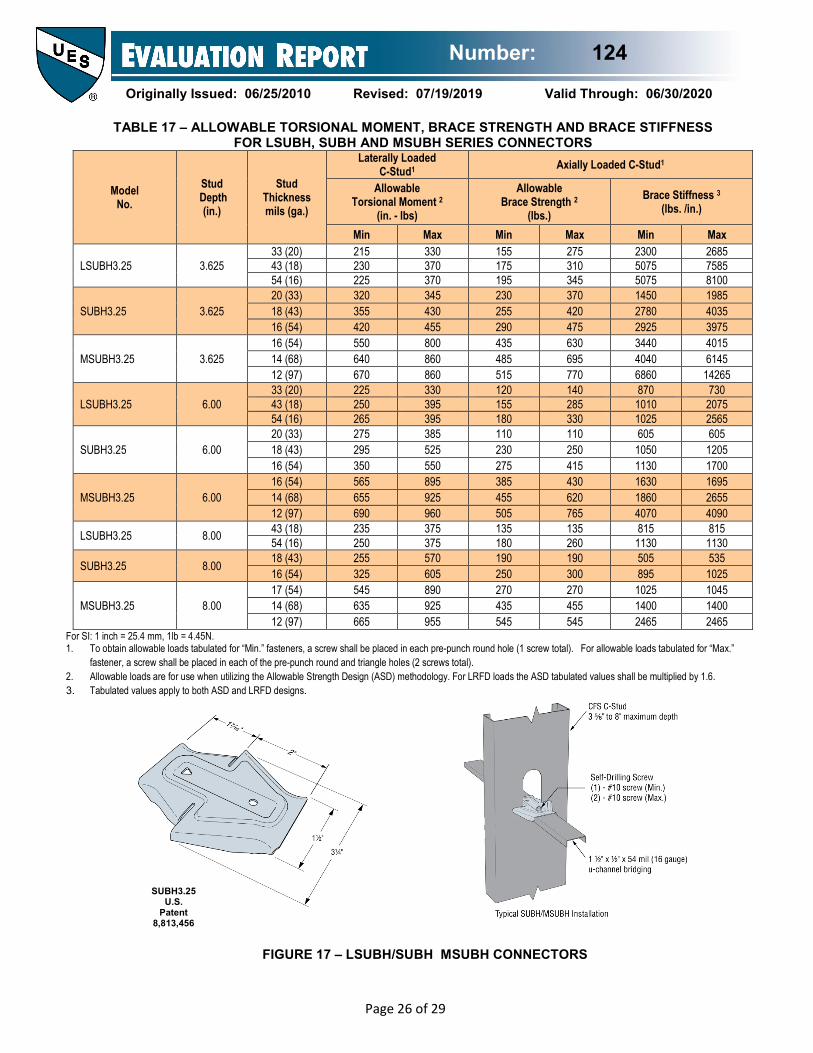
report provide dimensions, required fasteners, and ASD (allowable) loads. 3.1.23 TSP Stud to Track Tie: TSP stud to track ties are used to connect wall tracks and studs. The tie has a twist so that it fastens to the side of the stud. TSP is formed from No. 16 gage galvanized steel. Figure 14 and Table 14 of this report provide dimensions, required fasteners, and ASD (allowable) loads. 3.1.24 LTP5 Lateral Tie Plate: The LTP5 lateral tie plate are used to transfer shear between the top or bottom tracks to the rim joist or blocking, or between other parallel members. The LTP5 may be installed over either structural wood panel sheathing or sheet steel sheathing to connect the bottom track of a wall to the rim joist or blocking. The LTP5 lateral tie plate is manufactured from No. 20 gage galvanized steel with embossments along the length. Figure 15 and Table 15 of this report provide dimensions, required fasteners and ASD (allowable) loads. 3.1.25 DTC & STC Truss Clips: DTC and STC truss clips may be used as alignment control between a roof truss and non-load-bearing walls. The 1½ inch (38.1 mm) long slot permits vertical truss chord movement. DTC and STC connectors are formed from No. 18 gage galvanized steel. Figure 16 and Table 16 of this report provide dimensions, required fasteners, and ASD (allowable)loads. 3.1.26 LSUBH, SUBH and MSUBH Structural Bridging Connectors: LSUBH, SUBH and MSUBH structural bridging connectors are used to connect cold-formed steel C-studs to bridging U-channel installed through the web punch-out of the studs. Connectors are used as bracing to restrain twisting of studs loaded in the plane of the web and to restrain lateral translation of studs loaded in compression. Typical applications include attachments between cold-formed steel studs and bridging of exterior curtain-wall systems, exterior and interior bearing wall systems, interior non-bearing wall systems, and soffit or ceiling framing systems. Connectors are used with stud depths from 3⅝ to 8 inches (92 to 203.2 mm) utilizing cold-formed steel 1½ inch x ½ inch (38.1 mm x 12.7 mm) U-channel bridging members. LSUBH connectors are formed from No. 20 gage steel, and the SUBH connectors are formed from No. 18 gage steel, each with a slot width that accommodates a stud web thickness of 33 mils (0.83 mm)(No. 20 gage) to 54 mils (1.37 mm) (No. 16 gage). MSUBH connectors are formed from No. 14 gage steel with a slot width that accommodates a stud web thickness of 54 mils (1.37 mm) (No. 16 gage) to 97 mils (2.46 mm) (No. 12 gage). Figure 17 and Table 17 of this report provide dimensions, required fasteners, ASD (allowable)loads, allowable torsional moment, and brace stiffness.
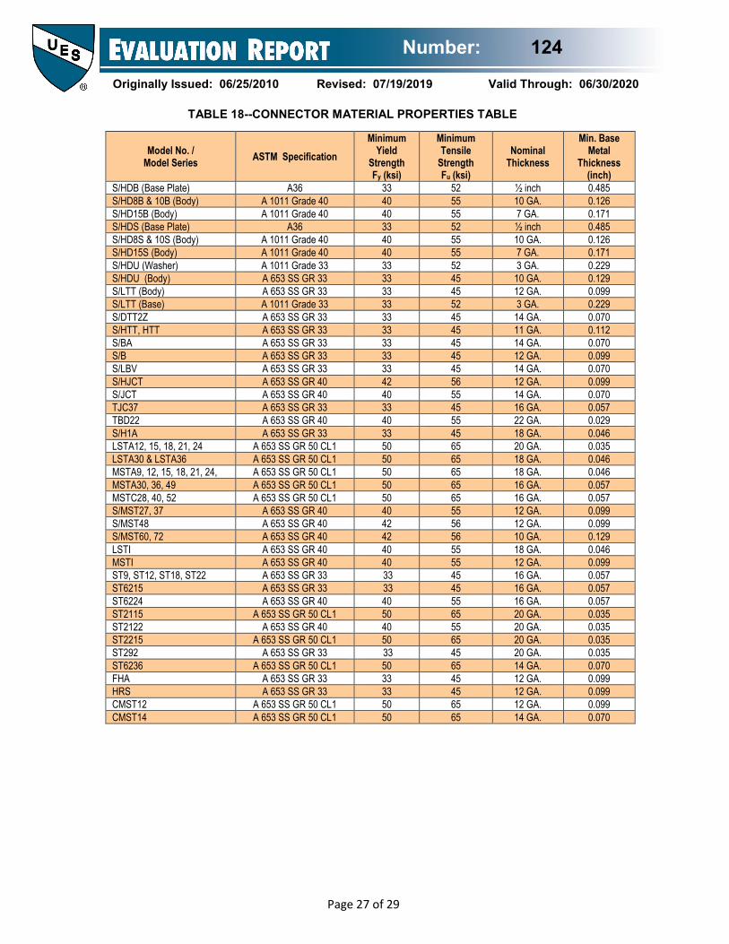
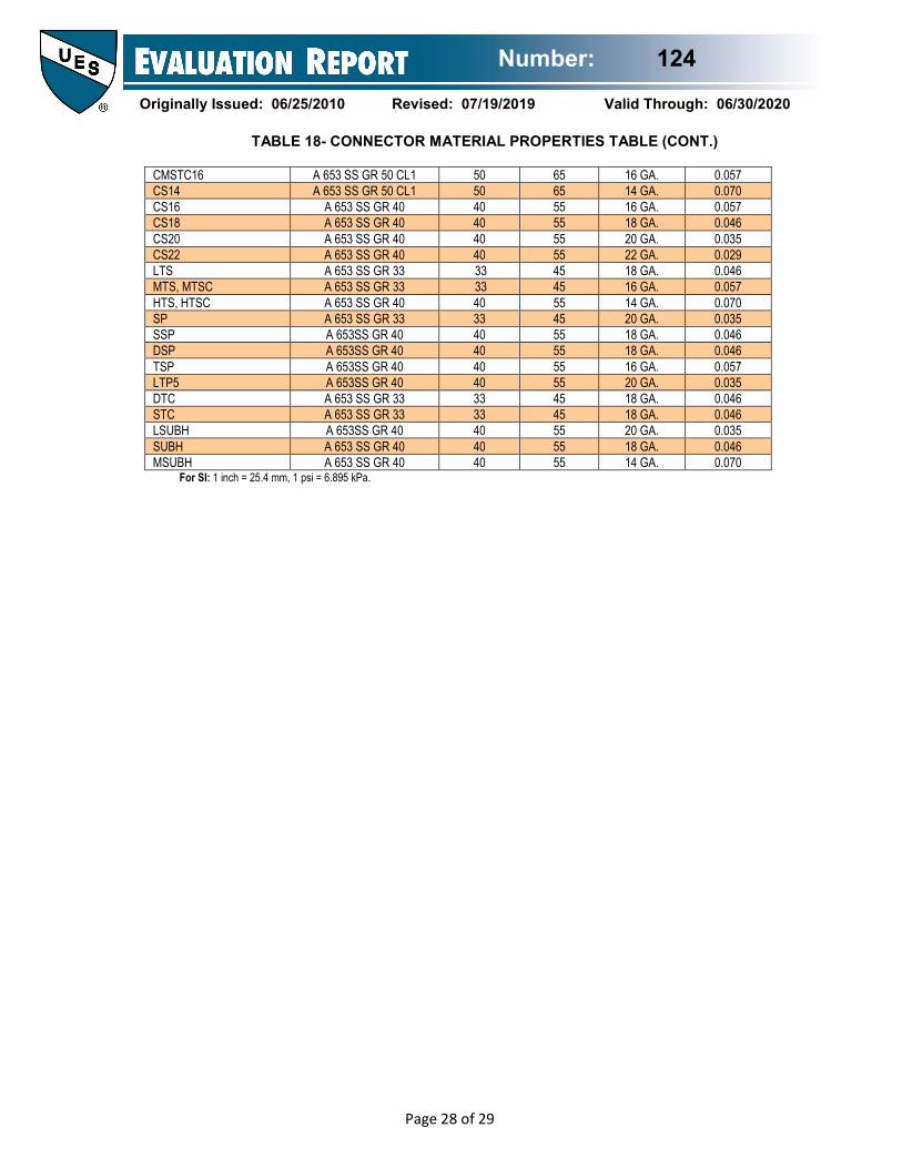
3.2 Material information 3.2.1 Steel: Galvanized steel connectors described in this report are manufactured from steel complying with ASTM A653 SS. Non-galvanized steel connectors comply with ASTM A36 or ASTM A1011. Steel used to fabricate the CFS connectors shown in this report comply with Connector Material Properties in Table 18 of this report. Connectors fabricated from steel complying with ASTM A653 have a minimum G90 zinc coating specification. Some models may also be available with either a G185 zinc coating (designated with a model number ending in the letter Z) or with a batch hot-dipped galvanized coating (designated with a model number ending with the letters HDG) with a minimum specified coating weight of 2.0 ounces of zinc per square foot of surface area (610 g/m2), total for both sides, in accordance with ASTM A123. Model numbers in this report do not list the Z or HDG ending, but the information shown applies. The lumber treater and the holder of this report (Simpson Strong-Tie Company) shall be contacted for recommendations on the connectors when in contact with preservative-treated or fire- retardant treated lumber. 3.2.2 Cold-Formed Steel Members and Structural Members: Structural cold-formed steel framing members that are attached to the connectors shown in this report shall comply with IBC Sections 2210 and 2211 as documented in an evaluation report by IAPMO UES or another accredited evaluation service agency. Structural steel members that are attached to the connectors shown in this report shall comply with IBC Section 2205 or an evaluation report stating IBC compliance by IAPMO UES or another approved and accredited evaluation service agency. At a minimum, the material specification for structural cold-formed steel framing members that are attached to the connectors shown in this report shall comply with ASTM A1003. Loads in this report are based on CFS members with a minimum yield strength, Fy, of 33 ksi (228 MPa) and a minimum tensile strength, Fu, of 45 ksi (310 MPa) for 43 mil (1.09 mm) (No, 18 gage) and thinner and a minimum yield strength, Fy, of 50 ksi (345 MPa) and a minimum tensile strength, Fu, of 60 ksi (414 MPa) for 54 mil (1.37 mm) (No. 16 gage) and thicker. Cold-formed steel 1½ inch x ½ inch U-channel (38.1 mm x 12.7 mm) bridging members used with SUBH and MSUBH bridging connectors shall have a minimum base metal thickness of 0.0566 inch (1.43 mm) with a minimum of yield strength of 33 ksi (228 MPa) and a minimum tensile strength of 45 ksi (310 MPa) Use of the connectors in this report with materials not complying with the requirements of this section is outside the scope of this report. 3.2.3 Wood: Wood members with which the connectors are used shall be either sawn lumber or engineered lumber having a minimum specific gravity of 0.50 (minimum equivalent specific gravity of 0.50 for engineered lumber), and having a
Number: 124
Originally Issued: 06/25/2010 Revised: 07/19/2019 Valid Through: 06/30/2020
Page 5 of 29
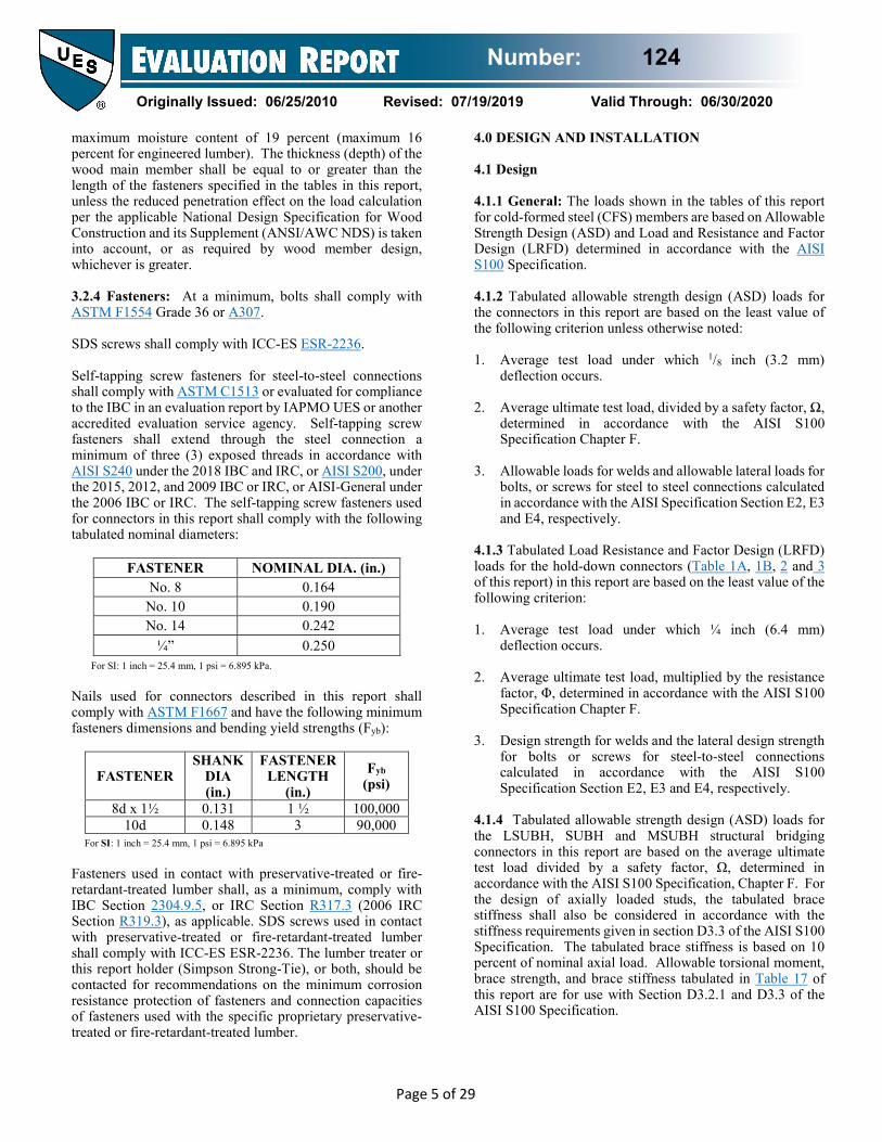
maximum moisture content of 19 percent (maximum 16 percent for engineered lumber). The thickness (depth) of the wood main member shall be equal to or greater than the length of the fasteners specified in the tables in this report, unless the reduced penetration effect on the load calculation per the applicable National Design Specification for Wood Construction and its Supplement (ANSI/AWC NDS) is taken into account, or as required by wood member design, whichever is greater. 3.2.4 Fasteners: At a minimum, bolts shall comply with ASTM F1554 Grade 36 or A307. SDS screws shall comply with ICC-ES ESR-2236. Self-tapping screw fasteners for steel-to-steel connections shall comply with ASTM C1513 or evaluated for compliance to the IBC in an evaluation report by IAPMO UES or another accredited evaluation service agency. Self-tapping screw fasteners shall extend through the steel connection a minimum of three (3) exposed threads in accordance with AISI S240 under the 2018 IBC and IRC, or AISI S200, under the 2015, 2012, and 2009 IBC or IRC, or AISI-General under the 2006 IBC or IRC. The self-tapping screw fasteners used for connectors in this report shall comply with the following tabulated nominal diameters:
FASTENER NOMINAL DIA. (in.) No. 8 0.164
No. 10 0.190 No. 14 0.242
¼” 0.250 For SI: 1 inch = 25.4 mm, 1 psi = 6.895 kPa.
Nails used for connectors described in this report shall comply with ASTM F1667 and have the following minimum fasteners dimensions and bending yield strengths (Fyb):
FASTENER SHANK
DIA (in.)
FASTENER LENGTH
(in.)
Fyb (psi)
8d x 1½ 0.131 1 ½ 100,000 10d 0.148 3 90,000
For SI: 1 inch = 25.4 mm, 1 psi = 6.895 kPa Fasteners used in contact with preservative-treated or fire-retardant-treated lumber shall, as a minimum, comply with IBC Section 2304.9.5, or IRC Section R317.3 (2006 IRC Section R319.3), as applicable. SDS screws used in contact with preservative-treated or fire-retardant-treated lumber shall comply with ICC-ES ESR-2236. The lumber treater or this report holder (Simpson Strong-Tie), or both, should be contacted for recommendations on the minimum corrosion resistance protection of fasteners and connection capacities of fasteners used with the specific proprietary preservative-treated or fire-retardant-treated lumber.
4.0 DESIGN AND INSTALLATION 4.1 Design 4.1.1 General: The loads shown in the tables of this report for cold-formed steel (CFS) members are based on Allowable Strength Design (ASD) and Load and Resistance and Factor Design (LRFD) determined in accordance with the AISI S100 Specification. 4.1.2 Tabulated allowable strength design (ASD) loads for the connectors in this report are based on the least value of the following criterion unless otherwise noted: 1. Average test load under which 1/8 inch (3.2 mm)
deflection occurs. 2. Average ultimate test load, divided by a safety factor, Ω,
determined in accordance with the AISI S100 Specification Chapter F.
3. Allowable loads for welds and allowable lateral loads for
bolts, or screws for steel to steel connections calculated in accordance with the AISI Specification Section E2, E3 and E4, respectively.
4.1.3 Tabulated Load Resistance and Factor Design (LRFD) loads for the hold-down connectors (Table 1A, 1B, 2 and 3 of this report) in this report are based on the least value of the following criterion: 1. Average test load under which ¼ inch (6.4 mm)
deflection occurs. 2. Average ultimate test load, multiplied by the resistance
factor, Φ, determined in accordance with the AISI S100 Specification Chapter F.
3. Design strength for welds and the lateral design strength
for bolts or screws for steel-to-steel connections calculated in accordance with the AISI S100 Specification Section E2, E3 and E4, respectively.
4.1.4 Tabulated allowable strength design (ASD) loads for the LSUBH, SUBH and MSUBH structural bridging connectors in this report are based on the average ultimate test load divided by a safety factor, Ω, determined in accordance with the AISI S100 Specification, Chapter F. For the design of axially loaded studs, the tabulated brace stiffness shall also be considered in accordance with the stiffness requirements given in section D3.3 of the AISI S100 Specification. The tabulated brace stiffness is based on 10 percent of nominal axial load. Allowable torsional moment, brace strength, and brace stiffness tabulated in Table 17 of this report are for use with Section D3.2.1 and D3.3 of the AISI S100 Specification.

Number: 124
Originally Issued: 06/25/2010 Revised: 07/19/2019 Valid Through: 06/30/2020
Page 6 of 29
Connected cold-formed steel members shall be analyzed for load carrying capacity at the connection in accordance with the AISI S100 Specification. For connectors attached to wood members, the allowable loads shown in this report are based on allowable stress design and include the load duration factor, CD, corresponding with the applicable loads in accordance with the National Design Specification for Wood Construction and its supplement (ANSI/AWC NDS). Tabulated allowable loads apply to products connected to wood used under dry conditions and where sustained temperatures are 100°F (37.8°C) or less. When products are installed to wood having a moisture content greater than 19 percent (16 percent for engineered wood products), or where wet service is expected, the allowable tension loads shall be adjusted by the wet service factor, CM, specified in the ANSI/AWCNDS. When connectors are installed in wood that will experience sustained exposure to temperatures exceeding 100°F (37.8°C), the allowable loads in this report shall be adjusted by the temperature factor, Ct, specified in the ANSI/AWC NDS. Connected wood members shall be analyzed for load carrying capacity at the connection in accordance with ANSI/AWC NDS. Design of wood or steel members fastened to bolt or screw hold-down devices shall consider combined stresses due to axial tension and flexural bending induced by eccentricity in the connection. Stresses shall be evaluated at the critical net section. Connections (e.g., hold-downs) of a discontinuous system (e.g., shear wall) to the supporting member (e.g., beam) shall comply with ASCE 7 Section 12.3.3.3. Additional drift may occur, depending on the type of supporting member that is used, and shall be considered by the registered design professional. The design of connectors used in cold-forned steel construction to resist earthquake forces shall comply with 2018 IBC Section 2211.1; 2015, 2012 and 2009 IBC Section 2211.6; or 2006 IBC Section 2211.5. Adequate embedment length and anchorage details, including edge and end distances shall be determined in accordance with Chapters 19 or 21 of the IBC as applicable, for design of anchorage to concrete and masonry structural members except for those structures designed in accordance with the IRC, or the conventional light-frame construction provisions of Section 2308 of the IBC. Where anchors are designed to resist seismic loads, the seismic load effects shall include overstrength in accordance with ASCE-7-10 Supplement 1 or ASCE 7-16.
4.2 Installation Installation of the connectors shall be in accordance with this evaluation report and the manufacturer’s published installation instructions. The location of the connectors shall comply with the approved plans. In the event of a conflict between this report and the manufacturer’s published installation instructions, the more restrictive governs. 4.3 Special Inspection 4.3.1 A statement of special inspection shall be prepared by the registered design professional in responsible charge and submitted to the code official for approval when required by Section 1704.3 of the 2018, 2015 or 2012 IBC; or Section 1705 of the 2009 or 2006 IBC. A statement of responsibility shall be submitted by each responsible contractor to the code official for approval when required by 2018, 2015 or 2012 IBC Section 1704.4, 2009 IBC Section 1709, or 2006 IBC Section 1706. 4.3.2 Periodic special inspection shall be conducted when connectors are components within the main wind-force-resisting system of structures constructed in areas listed in the 2018 or 2015 IBC Section 1705.11, 2012 IBC Section 1705.10, 2009 IBC Section 1706.1, or 2006 IBC Section 1705.4. Special inspection requirements do not apply to structures, or portions thereof, that qualify for an exception pursuant to 2018 or 2015 IBC Sections 1704.2, 1705.3, 1705.11.1, 1705.11.2, 2012 IBC Sections 1704.2, 1705.3, 1705.10.1, 1705.10.2, 2009 IBC Sections 1704.1, 1704.4, 1706.2, 1706.3, or 2006 IBC Section 1704.1 and 1704.4. 4.3.3 Periodic special inspection for seismic resistance shall be conducted in accordance with 2018 or 2015 IBC Section 1705.12, 2012 IBC Section 1705.11, or 2009 or 2006 Section 1707 where required. Special inspection requirements for seismic resistance do not apply to structures, or portions thereof, that qualify for an exception pursuant to 2018 or 2015 IBC Sections 1704.2, 1705.3, 1705.12, 1705.12.3, 2012 IBC Sections 1704.2, 1705.3, 1705.11, 1705.11.3, 2009 or 2006 IBC Sections 1704.1, 1704.4, 1705.3, 1707.3 or 1707.4. 4.3.4 For installations under the IRC, special inspection is not normally required. However, for an engineered design where calculations are required to be signed by a registered design professional, periodic special inspection requirements and exemptions are as stated in Sections 4.3.2 and 4.3.3 of this report as applicable for installations under the IRC. 4.3.5 Special inspections for anchor bolts in concrete or masonry shall be conducted in accordance with Section 1705.3 or 1705.4 of the 2018, 2015, or 2012 IBC, or Section 1704.4 or 1704.5 of the 2009 or 2006 IBC.

Number: 124
Originally Issued: 06/25/2010 Revised: 07/19/2019 Valid Through: 06/30/2020
Page 7 of 29
5.0 LIMITATIONS The Simpson Strong-Tie products described in this report comply with, or are suitable alternatives to what is specified in the codes listed in Section 1.0 of this report subject to the following limitations: 5.1 Connectors shall be manufactured, identified and installed in accordance with this report and the manufacturer’s published installation instructions. Where conflicts occur, the more restrictive governs. A copy of the instructions shall be available at the jobsite at all times during installation. 5.2 Calculations showing compliance with this report shall be submitted to the code official. The calculations shall be prepared by a registered design professional where required by the statues of the jurisdiction in which the project is to be constructed. 5.3 Adjustment factors noted in Section 4.1 of this report and the applicable codes shall be applied to design loads when warranted by the service conditions. 5.4 Connected steel members, connected wood members and fasteners shall comply, respectively, with Sections 3.2.2, 3.2.3 and 3.2.4 of this report. 5.5 Use of connectors with preservative-treated or fire-retardant-treated lumber shall be in accordance with Section 3.2.1 of this report. Use of fasteners with preservative-treated or fire-retardant-treated lumber shall be in accordance with Section 3.2.4 of this report. 5.6 Special inspection is provided in accordance with Section 4.3 of this report. 5.7 Simpson Strong-Tie Connectors for Cold-Formed Steel (CFS) Construction are fabricated at Simpson Strong-Tie facilities under a quality control program that equals or exceeds the Minimum Requirements for IAPMO UES Listee's Quality Assurance System
or
IAPMO UES ER-124 6.0 SUBSTANTIATING DATA Data in accordance with the ICC-ES Acceptance Criteria for Connectors Used With Cold-Formed Steel Structural Members (AC261), approved October 2011, editorially revised August 2018. Test results are from laboratories in compliance with ISO/IEC 17025. 7.0 IDENTIFICATION A label shall be affixed on at least one of the following: product, packaging, installation instructions or descriptive literature. The label shall include the company name or trademark, model number, and the IAPMO Uniform ES Mark of Conformity the name of the inspection agency (when applicable) and the Evaluation Report Number (ER-124) to identify the products recognized in this report. A die-stamp label may also substitute for the label. Either Mark of Conformity as shown below may be used:
Brian Gerber, P.E., S.E. Vice President, Technical Operations
Uniform Evaluation Service
Richard Beck, PE, CBO, MCP Vice President, Uniform Evaluation Service
GP Russ Chaney CEO, The IAPMO Group
For additional information about this evaluation report please visit www.uniform-es.org or email us at [email protected]

Number: 124
Originally Issued: 06/25/2010 Revised: 07/19/2019 Valid Through: 06/30/2020
Page 8 of 29
TABLE 1A – TENSION LOADS AND DISPLACEMENTS FOR S/HDS AND S/HDB SERIES HOLD-DOWNS
Model Height (in)
Fasteners Framing
Member(s)5 No.-Mil (ga)
ASD LRFD Nominal Tension Load8,9
(lbs)
Anchor Bolt
Dia.1,2 (in)
Framing Fasteners
Tension Load (lbs)
Displacement at ASD Load7
(in)
Tension Load (lbs)
Displacement at LRFD Load7
(in)
S/HD8S 11 7/8 17 - #14 Screws3
2-33 (2-20ga) 7335 0.120 11715 0.204 13720 2-43 (2-18ga) 8750 0.086 13975 0.146 21435 2-54 (2-16ga) 8855 0.106 14145 0.162 21700 1-97 (1-12ga)
PACO6 11030 0.091 17620 0.146 27025
Steel Fixture 10840 0.053 17335 0.072 32525
S/HD10S 13½ 7/8 22 - #14 Screws3
2-33 (2-20ga) 7400 0.122 11815 0.192 13835 2-43 (2-18ga) 11120 0.112 17755 0.124 20795 2-54 (2-16ga) 12220 0.096 19520 0.145 29940 1-97 (1-12ga)
PACO6 14840 0.085 23705 0.148 34135
Steel Fixture 12375 0.043 19820 0.061 33535
S/HD15S 17 1 30 - #14 Screws3
2-43 (2-18ga) 12110 0.096 19340 0.164 22645 2-54 (2-16ga) 13500 0.110 21565 0.130 33075 1-97 (1-12ga)
PACO6 16420 0.078 26230 0.135 40230
Steel Fixture 15810 0.043 25320 0.065 42845
S/HD8B 11 7/8 2 - ¾” Dia. Bolts4
2-33 (2-20ga) 3895 0.081 5620 0.144 8645 2-43 (2-18ga) 5345 0.098 7710 0.146 11865 2-54 (2-16ga) 8950 0.082 14280 0.141 20310 1-97 (1-12ga)
PACO6 8090 0.088 12905 0.167 18370
Steel Fixture 9080 0.069 14545 0.104 22975
S/HD10B 13½ 7/8 3 - ¾” Dia. Bolts4
2-33 (2-20ga) 5840 0.070 8430 0.124 12970 2-43 (2-18ga) 8015 0.087 11565 0.120 17795 2-54 (2-16ga) 12090 0.125 19720 0.230 28050 1-97 (1-12ga)
PACO6 13385 0.912 19355 0.119 28905
Steel Fixture 15635 0.102 24955 0.123 35495
S/HD15B 17 1 4 - ¾” Dia. Bolts4
2-43 (2-18ga) 10690 0.118 15425 0.179 22165 2-54 (2-16ga) 16020 0.090 25565 0.121 36360 1-97 (1-12ga)
PACO6 17850 0.103 25805 0.130 39700
Steel Fixture 18690 0.104 29825 0.139 42425 For SI: 1 inch = 25.4 mm, 1 lb = 4.45 N.
1. The Designer shall specify the foundation anchor material type, embedment and configuration. Some of the tabulated hold-down tension loads exceed the tension strength of typical ASTM F1554 Grade 36 or A307 anchor bolts.
2. A foundation anchor bolt washer is not required. 3. 1/4-inch diameter self-tapping screws may be substituted for #14 self-tapping screws. 4. A round steel standard plate washer conforming to Section 3.1.1 of this report is required to be installed between the framing member bolt nut and the framing member for
the S/HDB series hold-downs. 5. The Designer shall specify and detail the connection of the back-to-back full height framing members. 6. PACO columns are manufactured by PACO Steel & Engineering Corp. Recognition of the column is beyond the scope of this report. 7. Hold-down displacement at tabulated ASD and LRFD loads is the difference in the displacement measured between the anchor bolt and back of the hold-down that’s
attached to the framing member(s) when loaded to the ASD and LRFD static test load, respectively. Deflection includes fastener slip, hold-down elongation and anchor bolt elongation (L=4 inches).
8. The Nominal Tension Load is the average ultimate (peak) load taken from tests in accordance with AISI S100 Chapter F. When hold-downs are used in CFS framed shear walls or diagonal strap braced walls with an R-coefficient greater than 3, the AISI S213 Lateral Design Section C5 requires hold-downs in shear walls have the nominal strength to resist the lesser of the amplified seismic load or the load the system can deliver and hold-downs in diagonal strap braced walls have the nominal strength to resist the lesser of the amplified seismic load or the expected yield strength of the diagonal strap bracing member.
9. When used in lateral force resisting systems, hold-downs shall be designed for the expected strength of designated seismic force reisting systems as specified in Section B3 and Chapter E of AISI S400.
Number: 124
Originally Issued: 06/25/2010 Revised: 07/19/2019 Valid Through: 06/30/2020
Page 9 of 29
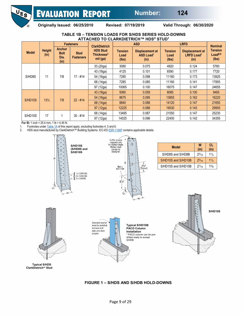
TABLE 1B – TENSION LOADS FOR S/HDS SERIES HOLD-DOWNS ATTACHED TO CLARKDIETRICH™ HDS® STUD1
Model Height (in)
Fasteners ClarkDietrich HDS Stud
Thickness2 mil (ga)
ASD LRFD Nominal Tension Load8,9
(lbs)
Anchor Bolt Dia. (in)
Stud Fasteners
Tension Load (lbs)
Displacement at ASD Load7
(in)
Tension Load (lbs)
Displacement at LRFD Load7
(in)
S/HD8S 11 7/8 17 - #14
33 (20ga) 3080 0.075 4920 0.124 5760 43 (18ga) 4125 0.101 6590 0.177 7720 54 (16ga) 7285 0.098 11160 0.173 13925 68 (14ga) 7285 0.085 11160 0.141 17855 97 (12ga) 10065 0.100 16075 0.147 24655
S/HD10S 13½ 7/8 22 - #14
43 (18ga) 5060 0.059 8085 0.100 9465 54 (16ga) 8675 0.095 13855 0.162 16220 68 (14ga) 8840 0.088 14120 0.147 21655 97 (12ga) 12225 0.088 19530 0.143 29955
S/HD15S 17 1 30 - #14 68 (14ga) 13495 0.087 21550 0.147 25235 97 (12ga) 14025 0.096 22400 0.142 34355
For SI: 1 inch = 25.4 mm, 1 lb = 4.45 N. 1. Footnotes under Table 1A of this report apply, excluding footnotes 4, 5 and 6. 2. HDS stud manufactured by ClarkDietrich™ Building Systems. ICC-ES ESR-1166P contains applicable details.
Model W (in)
CL (in)
S/HD8S and S/HD8B 25/16 11/2 S/HD10S and S/HD10B 25/16 11/2 S/HD15S and S/HD15B 27/16 13/8
S/HD15S (S/HD8S and S/HD10S
Typical S/HD10B PACO Column Installation * PACO column can be pre-drilled ready to accept S/HDB
Typical S/HDS ClarkDietrich™ Stud
FIGURE 1 – S/HDS AND S/HDB HOLD-DOWNS
S/HD10S

Number: 124
Originally Issued: 06/25/2010 Revised: 07/19/2019 Valid Through: 06/30/2020
Page 10 of 29
TABLE 2 – TENSION LOADS AND DISPLACEMENTS FOR S/HDU SERIES HOLD-DOWNS
Model Height (in.)
Fasteners Framing
Member(s)5 No.-mil (ga)
ASD LRFD Nominal Tension Load7,8
(lbs)
Anchor Bolt Dia1,2 (in)
Framing Fasteners4
Tension Load (lbs)
Displacement at ASD Load6
(in)
Tension Load (lbs)
Displacement at LRFD Load6
(in)
S/HDU4 77/8 5/8 6-#14
2-33 (2-20ga) 2320 0.093 3705 0.149 5685 2-43 (2-18ga) 3825 0.115 6105 0.190 9365 2-54 (2-16ga) 3970 0.093 6345 0.156 9730 Steel Fixture 4470 0.063 7165 0.103 12120
S/HDU6 103/8 5/8 12-#14
2-33 (2-20ga) 4895 0.125 8495 0.250 10470 2-43 (2-18ga) 6125 0.119 9690 0.250 15460 2-54 (2-16ga) 6125 0.108 9785 0.234 15005 Steel Fixture 5995 0.060 9580 0.136 14695
S/HDU9 127/8 ⅞ 18-#14
2-33 (2-20ga) 6965 0.103 11125 0.189 13165 2-43 (2-18ga) 9255 0.125 15485 0.250 21810 2-54 (2-16ga) 9990 0.106 15960 0.225 24480 Steel Fixture 12715 0.125 20510 0.177 31455
S/HDU11 165/8 ⅞3 27-#14 2-33 (2-20ga) 6965 0.103 11125 0.189 13165 For SI: 1 inch = 25.4 mm, 1 lb = 4.45 N.
1. The Designer shall specify the foundation anchor material type, embedment and configuration. Some of the tabulated hold-down tension loads exceed the tension strength of typical ASTM F1554 Grade 36 or A307 anchor bolts.
2. A foundation anchor bolt washer is not required. 3. A heavy hex nut for the anchor bolt is required to achieve the tablulated loads for S/HDU11. 4. 1/4-inch self-tapping screws may be substituted for #14 self-tapping screws. 5. The Designer shall specify and detail the connection of the back-to-back full height framing members. 6. Hold-down displacement at tabulated ASD and LRFD loads is the difference in the displacement measured between the anchor bolt and back of the hold-down that’s
attached to the framing member(s) when loaded to the ASD and LRFD static test load, respectively. Deflection fastener slip, hold-down elongation and anchor bolt elongation (L=4”).
7. The Nominal Tension Load is the average ultimate (peak) load from tests in accordance with AISI S100 Chapter F. When hold-downs are used in CFS framed shear walls or diagonal strap braced walls with an R-coefficient greater than 3, the AISI S213 Lateral Design Section C5 requires hold-downs in shear walls have the nominal strength to resist the lesser of the amplified seismic load or the load the system can deliver and hold-downs in diagonal strap braced walls have the nominal strength to resist the lesser of the amplified seismic load or the expected yield strength of the diagonal strap bracing member.
8. When used in lateral force resisting systems, hold-downs shall be designed for the expected strength of designated seismic force resisting systems as specified in Section B3 and Chapter E of AISI S400.
FIGURE 2 – S/HDU HOLD-DOWN

Number: 124
Originally Issued: 06/25/2010 Revised: 07/19/2019 Valid Through: 06/30/2020
Page 11 of 29
TABLE 3 – TENSION LOADS AND DISPLACEMENTS FOR S/LTT, S/DTT, S/HTT, AND HTT SERIES HOLD-DOWNS1
Model Height (in)
Fasteners Framing Member(s)3
No.-mil (ga)
ASD LRFD Nominal Tension Load5,6
(lbs)
Anchor Bolt Dia.2 (in)
Framing Fasteners
Tension Load (lbs)
Displacement at ASD Load4
(in)
Tension Load (lbs)
Displacement at LRFD Load4
(in)
S/LTT20 20 1/2 8 - #10 1-33 (1-20ga) 1200 0.125 1890 0.250 4625
S/DTT2Z 615/16 1/2 8-#14
1-33 (1-20ga) 1570 0.138 2200 0.250 4265
1-43 (1-18ga) 1685 0.151 2355 0.250 5570
2-33 (2-20ga) 1735 0.153 2430 0.250 5735
S/HTT14 15 5/8 16 - #10
1-33 (1-20ga) 2775 0.108 4430 0.172 6800
2-33 (2-20ga) 3850 0.125 6700 0.250 11590
HTT4 12⅜ 5/8 18 - #10
1-33 (1-20ga) 3180 0.104 4770 0.187 8215
2-33 (2-20ga) 4395 0.125 6675 0.250 11835
HTT5 16 5/8 26 - #10
1-43 (1-18ga) 4240 0.125 6505 0.250 11585
2-43 (2-18ga) 4670 0.125 6970 0.250 12195
1-54 (1-16ga) 4150 0.125 6425 0.250 12365
For SI: 1 inch = 25.4 mm, 1 lb = 4.45 N. 1. The Designer shall specify the foundation anchor material type, embedment and configuration. 2 Foundation anchor bolt washer is not required. 3. The Designer shall specify and detail the connection of the back-to-back full height studs. 4. Hold-down displacement at tabulated ASD and LRFD loads is the difference in the displacement measured between the anchor bolt and back of the hold-
down that’s attached to the framing member(s) when loaded to the ASD and LRFD static test load, respectively. Deflection fastener slip, hold-down elongation and anchor bolt elongation (L=4 inches).
5. The Nominal Tension Load is the average ultimate (peak) load from tests in accordance with AISI S100 Chapter F. When hold-downs are used in CFS framed shear walls or diagonal strap braced walls with an R-coefficient greater than 3, the AISI S213 Lateral Design Section C5 requires hold-downs in shear walls have the nominal strength to resist the lesser of the amplified seismic load or the load the system can deliver and hold-downs in diagonal strap braced walls have the nominal strength to resist the lesser of the amplified seismic load or the expected yield strength of the diagonal strap bracing member.
1. When used in lateral force resisting systems, hold-downs shall be designed for the expected strength of designated seismic force resisting systems as specified in Section B3 and Chapter E of AISI S400.
S/LTT20 S/DTT2Z S/HTT14 HTT5 (HTT4 Similar) Typical S/HTT14
Installation
FIGURE 3 – S/LTT, S/DTT, S/HTT AND HTT HOLD-DOWNS
Number: 124
Originally Issued: 06/25/2010 Revised: 07/19/2019 Valid Through: 06/30/2020
Page 12 of 29
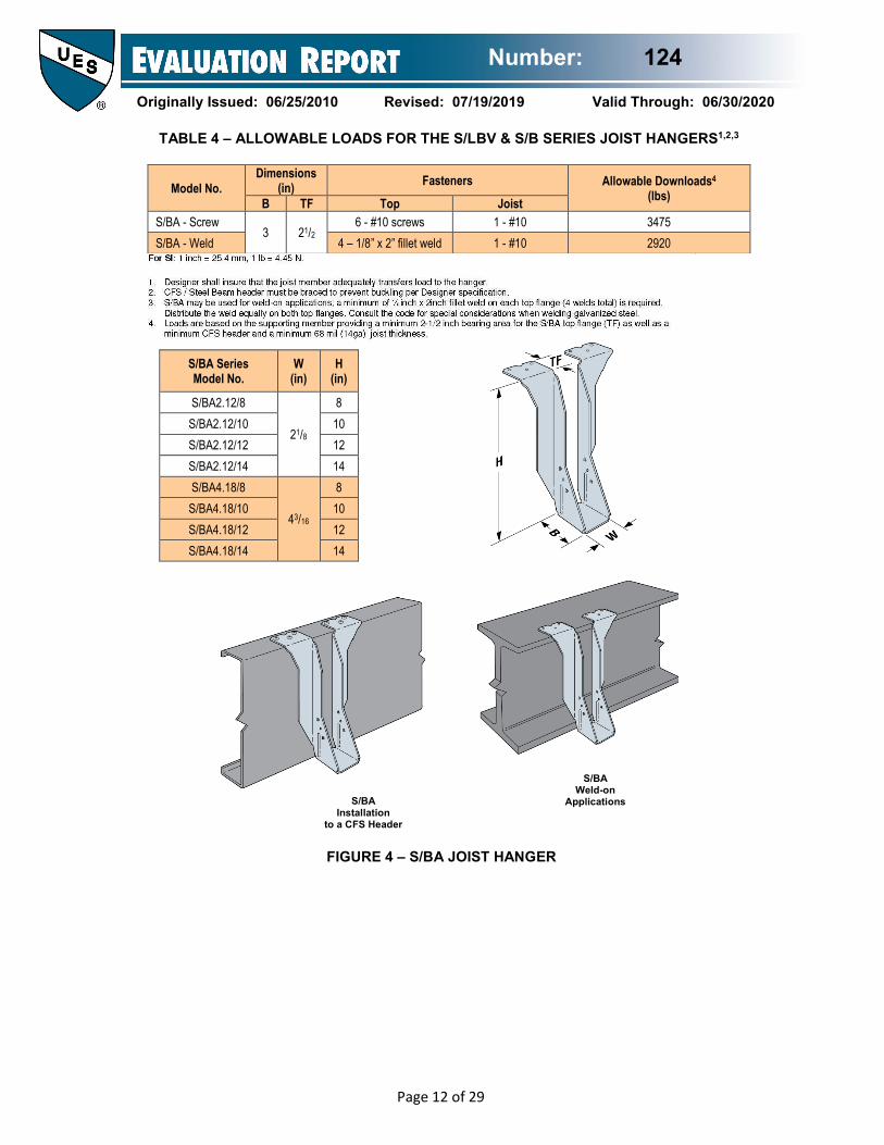
TABLE 4 – ALLOWABLE LOADS FOR THE S/LBV & S/B SERIES JOIST HANGERS1,2,3
Model No. Dimensions
(in) Fasteners Allowable Downloads4
(lbs) B TF Top Joist S/BA - Screw
3 21/2 6 - #10 screws 1 - #10 3475
S/BA - Weld 4 – 1/8” x 2” fillet weld 1 - #10 2920
S/BA Series Model No.
W (in)
H (in)
S/BA2.12/8
21/8
8 S/BA2.12/10 10 S/BA2.12/12 12 S/BA2.12/14 14 S/BA4.18/8
43/16
8 S/BA4.18/10 10 S/BA4.18/12 12 S/BA4.18/14 14
FIGURE 4 – S/BA JOIST HANGER
S/BA Weld-on
Applications S/BA Installation
to a CFS Header
Number: 124
Originally Issued: 06/25/2010 Revised: 07/19/2019 Valid Through: 06/30/2020
Page 13 of 29
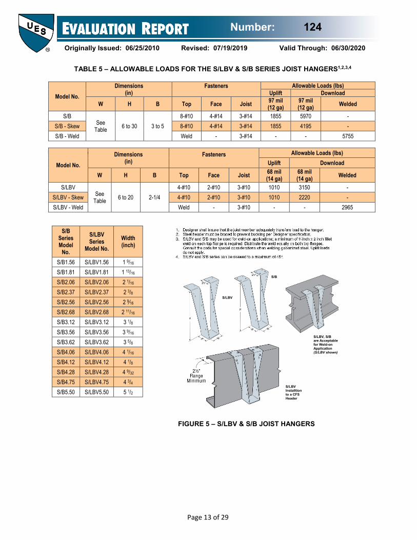
Model No. Dimensions
(in) Fasteners
Allowable Loads (lbs)
Uplift Download
W H B Top Face Joist 97 mil (12 ga)
97 mil (12 ga) Welded
S/B See
Table 6 to 30 3 to 5 8-#10 4-#14 3-#14 1855 5970 -
S/B - Skew 8-#10 4-#14 3-#14 1855 4195 - S/B - Weld Weld - 3-#14 - - 5755
Model No. Dimensions
(in) Fasteners
Allowable Loads (lbs)
Uplift Download
W H B Top Face Joist 68 mil (14 ga)
68 mil (14 ga) Welded
S/LBV See
Table 6 to 20 2-1/4 4-#10 2-#10 3-#10 1010 3150 -
S/LBV - Skew 4-#10 2-#10 3-#10 1010 2220 - S/LBV - Weld Weld - 3-#10 - - 2965
S/B Series Model
No.
S/LBV Series
Model No. Width (inch)
S/B1.56 S/LBV1.56 1 9/16 S/B1.81 S/LBV1.81 1 13/16 S/B2.06 S/LBV2.06 2 1/16 S/B2.37 S/LBV2.37 2 3/8 S/B2.56 S/LBV2.56 2 9⁄16 S/B2.68 S/LBV2.68 2 11/16 S/B3.12 S/LBV3.12 3 1/8 S/B3.56 S/LBV3.56 3 9/16 S/B3.62 S/LBV3.62 3 5/8 S/B4.06 S/LBV4.06 4 1/16 S/B4.12 S/LBV4.12 4 1/8 S/B4.28 S/LBV4.28 4 9/32 S/B4.75 S/LBV4.75 4 3/4 S/B5.50 S/LBV5.50 5 1/2
TABLE 5 – ALLOWABLE LOADS FOR THE S/LBV & S/B SERIES JOIST HANGERS1,2,3,4
FIGURE 5 – S/LBV & S/B JOIST HANGERS
S/LBV
S/B
S/LBV, S/B are Acceptable for Weld-on Application (S/LBV shown)
S/LBV Installtion to a CFS Header
Number: 124
Originally Issued: 06/25/2010 Revised: 07/19/2019 Valid Through: 06/30/2020
Page 14 of 29
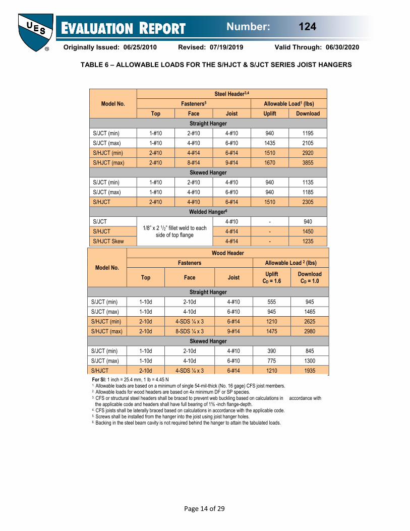
Model No. Steel Header3,4
Fasteners5 Allowable Load1 (lbs) Top Face Joist Uplift Download
Straight Hanger S/JCT (min) 1-#10 2-#10 4-#10 940 1195 S/JCT (max) 1-#10 4-#10 6-#10 1435 2105 S/HJCT (min) 2-#10 4-#14 6-#14 1510 2920 S/HJCT (max) 2-#10 8-#14 9-#14 1670 3855
Skewed Hanger S/JCT (min) 1-#10 2-#10 4-#10 940 1135 S/JCT (max) 1-#10 4-#10 6-#10 940 1185 S/HJCT 2-#10 4-#10 6-#14 1510 2305
Welded Hanger6
S/JCT 1/8” x 2 1/2” fillet weld to each
side of top flange
4-#10 - 940 S/HJCT 4-#14 - 1450 S/HJCT Skew 4-#14 - 1235
Model No.
Wood Header Fasteners Allowable Load 2 (lbs)
Top Face Joist Uplift CD = 1.6
Download CD = 1.0
Straight Hanger S/JCT (min) 1-10d 2-10d 4-#10 555 945 S/JCT (max) 1-10d 4-10d 6-#10 945 1465 S/HJCT (min) 2-10d 4-SDS ¼ x 3 6-#14 1210 2625 S/HJCT (max) 2-10d 8-SDS ¼ x 3 9-#14 1475 2980
Skewed Hanger S/JCT (min) 1-10d 2-10d 4-#10 390 845 S/JCT (max) 1-10d 4-10d 6-#10 775 1300 S/HJCT 2-10d 4-SDS ¼ x 3 6-#14 1210 1935
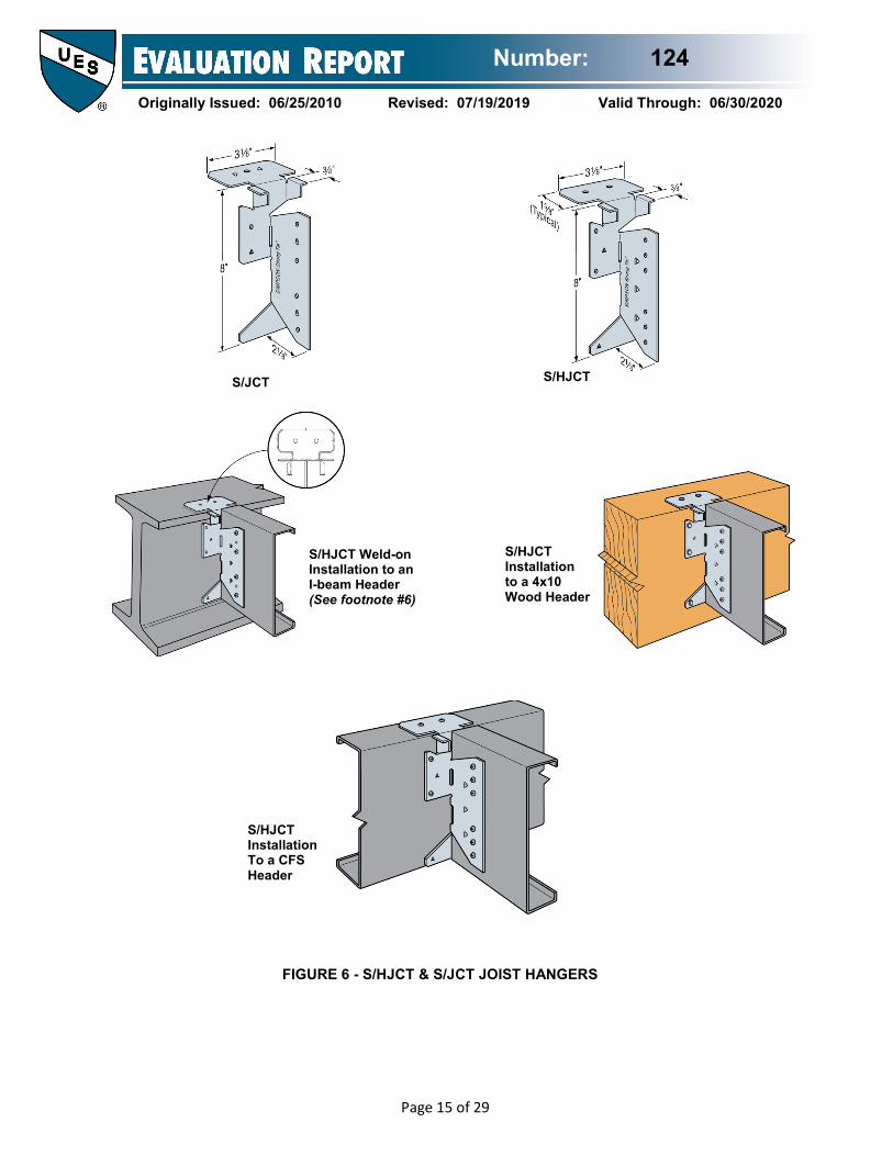
TABLE 6 – ALLOWABLE LOADS FOR THE S/HJCT & S/JCT SERIES JOIST HANGERS
For SI: 1 inch = 25.4 mm, 1 lb = 4.45 N 1. Allowable loads are based on a minimum of single 54-mil-thick (No. 16 gage) CFS joist members. 2. Allowable loads for wood headers are based on 4x minimum DF or SP species. 3. CFS or structural steel headers shall be braced to prevent web buckling based on calculations in accordance with
the applicable code and headers shall have full bearing of 1⅝ -inch flange-depth. 4. CFS joists shall be laterally braced based on calculations in accordance with the applicable code. 5. Screws shall be installed from the hanger into the joist using joist hanger holes. 6. Backing in the steel beam cavity is not required behind the hanger to attain the tabulated loads.
Number: 124
Originally Issued: 06/25/2010 Revised: 07/19/2019 Valid Through: 06/30/2020
Page 15 of 29
S/JCT S/HJCT
S/HJCT Weld-on Installation to an I-beam Header (See footnote #6)
S/HJCT Installation to a 4x10 Wood Header
S/HJCT Installation To a CFS Header
FIGURE 6 - S/HJCT & S/JCT JOIST HANGERS
Number: 124
Originally Issued: 06/25/2010 Revised: 07/19/2019 Valid Through: 06/30/2020
Page 16 of 29
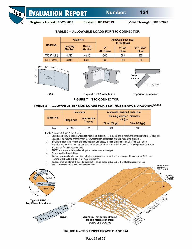
For SI: 1 inch = 25.4 mm, 1 lb = 4.45 N. 1. Load based on CFS trusses with a minimum yield strength, Fy, of 50 ksi and a minimum ultimate strength, Fu, of 65 ksi.
Load shall be reduced proportionally for lower steel strength (actual strength / specified strength). 2. Screws shall be installed into the dimpled areas and placed to maintain a minimum of ¼ inch strap edge
distance and a minimum of ½” center to center end distance. A minimum of 5/8 inch (3D) edge distance is to be maintained for the truss members.
3. TBD22 straps are to be installed at approximate 45-degress angles. 4. Straps shall be installed tight. 5. To resist construction forces, diagonal x-bracing is required at each end and every 10 truss spaces (20 ft max).
Reference SBCA CFSBCSI-08 for more information. 6. Trusses shall be laterally braced to resist out-of-plane forces at the end of the TBD22 diagonal braces. 7. TBD22 diagonal braces may be sheathed over.
Model No.
Fasteners Allowable Load (lbs) 43 mil (18ga)
Carrying Member
Carried Member 0°
(No Skew) 1°–60° Skew
61°– 67.5° Skew
TJC37 (Min) 4-#10 4-#10 660 565 475 TJC37 (Max) 6-#10 6-#10 680 630 530
Model No.
Fasteners2 Allowable Tension Loads (lbs)1
Strap Ends Intermediate Trusses
Framing Member Thickness mil (ga)
27 mil (22 ga) 33 mil (20 ga) TBD22 2 - #10 2 - #10 380 510
Top View Installation Typical TJC37 Installation TJC37
FIGURE 7 – TJC CONNECTOR
Typical TBD22 Top Chord Installation
TBD22 Minimum Temporary Bracing Recommendation from
SCBA CFSBCSI-08
FIGURE 8 – TBD TRUSS BRACE DIAGONAL
TABLE 7 – ALLOWABLE LOADS FOR TJC CONNECTOR
TABLE 8 – ALLOWABLE TENSION LOADS FOR TBD TRUSS BRACE DIAGONAL3,4,5,6,7

Number: 124
Originally Issued: 06/25/2010 Revised: 07/19/2019 Valid Through: 06/30/2020
Page 17 of 29
Model No.
Fasteners3 Framing Member
Thickness mil (ga)
Allowable Uplift Loads (lbs)2
Truss Track Stud Track / Wall Stud Thickness
33 mil (20 ga)
43 mil (18 ga)
54 mil (16 ga)
S/H1A
4-#10 3-#10 1-#10 27 (22 ga) 470 470 470 4-#10 3-#10 1-#10 33 (20 ga) 510 550 690 4-#10 3-#10 1-#10 43 (18 ga) 510 550 690 4-#10 3-#10 1-#10 54 (16 ga) 520 675 850
S/H1A
Typical S/H1A Installation
FIGURE 9 – S/H1A HURRICANE TIE
TABLE 9 – ALLOWABLE LOADS FOR THE S/H1A HURRICANE TIE1

Number: 124
Originally Issued: 06/25/2010 Revised: 07/19/2019 Valid Through: 06/30/2020
Page 18 of 29
Model No. Material Thick.
mil (ga)
Dimensions (in)
Fasteners (Total) Framing Member Thickness
Allowable Tention Loads (lbs)
W L 33 mil (20 ga)
43 mil (18 ga)
54 mil (16 ga)
33 mil (20 ga)
43 mil (18 ga)
54 mil (16 ga)
LSTA9
33 (20 ga)
1 1/4 9 8- #10 8- #10 8- #10 705 1120 1190 LSTA12 1 1/4 12 10- #10 10- #10 8- #10 885 1190 1190 LSTA15 1 1/4 15 12- #10 12- #10 10- #10 1060 1190 1190 LSTA18 1 1/4 18 14- #10 12- #10 10- #10 1190 1190 1190 LSTA21 1 1/4 21 14- #10 12- #10 10- #10 1190 1190 1190 LSTA24 1 1/4 24 14- #10 12- #10 10- #10 1190 1190 1190 ST292 2 1/16 9 5/16 12- #10 10- #10 10- #10 1060 1240 1240 ST2122 2 1/16 12 13/16 16- #10 12- #10 10- #10 1415 1500 1500 ST2115 3/4 16 5/16 8- #10 6- #10 4- #10 630 630 630 ST2215 2 1/16 16 5/16 20- #10 14- #10 10- #10 1765 1825 1825 LSTA30
43 mil (18 ga)
1 1/4 30 18- #10 12- #10 10- #10 1555 1555 1555 LSTA36 1 1/4 36 18- #10 16- #10 14- #10 1555 1555 1555 LSTI49 3 3/4 49 32- #10 32- #10 20- #10 2830 4050 4050 LSTI73 3 3/4 73 46- #10 32- #10 20- #10 4050 4050 4050 MSTA9 1 1/4 9 8- #10 8- #10 8- #10 705 1050 1555 MSTA12 1 1/4 12 10- #10 10- #10 8- #10 885 1315 1555 MSTA15 1 1/4 15 12- #10 12- #10 10- #10 1060 1555 1555 MSTA18 1 1/4 18 14- #10 12- #10 10- #10 1235 1555 1555 MSTA21 1 1/4 21 16- #10 12- #10 10- #10 1415 1555 1555 MSTA24 1 1/4 24 18- #10 12- #10 10- #10 1555 1555 1555 MSTA30
54 (16 ga)
1 1/4 30 22- #10 16- #10 12- #10 1945 1950 1950 MSTA36 1 1/4 36 24- #10 18- #10 16- #10 1950 1950 1950 ST6215 2 1/16 16 15/16 20- #10 16- #10 10- #10 1765 2025 2025 ST6224 2 1/16 23 5/16 28- #10 20- #10 12- #10 2455 2455 2455 ST9 1 1/4 9 8- #10 8- #10 8- #10 705 1050 1350 ST12 1 1/4 11 5/8 10- #10 10- #10 8- #10 885 1315 1350 ST18 1 1/4 17 3/4 14- #10 12- #10 12- #10 1235 1350 1350 ST22 1 1/4 21 5/8 20- #10 20- #10 20- #10 1350 1350 1350 MSTC28 3 28 1/4 36- #10 36- #10 30- #10 3180 4600 4600 MSTC40 3 40 1/4 52- #10 46- #10 46- #10 4595 4600 4600 MSTC52 3 52 1/4 54- #10 42- #10 42- #10 4600 4600 4600 MSTC66 68
(14 ga)
3 65 3/4 66- #10 46- #10 30- #10 5795 5795 5795 MSTC78 3 77 3/4 66- #10 46- #10 30- #10 5795 5795 5795 ST6236 2 1/16 33 13/16 40- #10 30- #10 18- #10 3535 3760 3760 HRS6
97 (12 ga)
1 3⁄8 6 6- #10 6- #10 6- #10 530 790 1600 HRS8 1 3⁄8 8 10- #10 10- #10 10- #10 885 1315 2670 HRS12 1 3⁄8 12 14- #10 14- #10 12- #10 1235 1840 2710 FHA6 1 7/16 6 3⁄8 8- #10 8- #10 8- #10 705 1050 2045 FHA9 1 7/16 9 8- #10 8- #10 8- #10 705 1050 2045 FHA12 1 7/16 11 5/8 8- #10 8- #10 8- #10 705 1050 2045 FHA18 1 7/16 17 3/4 8- #10 8- #10 8- #10 705 1050 2045 FHA24 1 7/16 23 7⁄8 8- #10 8- #10 8- #10 705 1050 2045 FHA30 1 7/16 30 8- #10 8- #10 8- #10 705 1050 2045 MSTI26 2 1/16 26 26- #10 26- #10 22- #10 2300 3420 5025 MSTI36 2 1/16 36 36- #10 36- #10 22- #10 3180 4735 5025 MSTI48 2 1/16 48 48- #10 40- #10 22- #10 4240 5025 5025 MSTI60 2 1/16 60 58- #10 40- #10 22- #10 5025 5025 5025 MSTI72 2 1/16 72 62- #10 58- #10 54- #10 5025 5025 5025 S/MST27 2 1/16 27 30- #10 30- #10 22- #10 2650 3945 5025 S/MST37 2 1/16 37 ½ 42- #10 40- #10 22- #10 3710 5025 5025 S/MST48 2 1/16 48 54- #10 40- #10 24- #10 4770 5155 5155 S/MST60 118
(10 ga) 2 1/16 60 68- #10 52- #10 30- #10 6010 6650 6650
S/MST72 2 1/16 72 76- #10 52- #10 30- #10 6650 6650 6650
Model No. Material Thick.
mil (ga)
Dimensions (in)
Fasteners (Total) Framing Member Thickness
W L 33 mil (20 ga)
43 mil (18 ga)
54 mil (16 ga)
33 mil (20 ga)
43 mil (18 ga)
54 mil (16 ga)
LSTA9
33 (20 ga)
1 1/4 9 8- #10 8- #10 8- #10 705 1120 1190 LSTA12 1 1/4 12 10- #10 10- #10 8- #10 885 1190 1190 LSTA15 1 1/4 15 12- #10 12- #10 10- #10 1060 1190 1190 LSTA18 1 1/4 18 14- #10 12- #10 10- #10 1190 1190 1190 LSTA21 1 1/4 21 14- #10 12- #10 10- #10 1190 1190 1190 LSTA24 1 1/4 24 14- #10 12- #10 10- #10 1190 1190 1190 ST292 2 1/16 9 5/16 12- #10 10- #10 10- #10 1060 1240 1240 ST2122 2 1/16 12 13/16 16- #10 12- #10 10- #10 1415 1500 1500 ST2115 3/4 16 5/16 8- #10 6- #10 4- #10 630 630 630 ST2215 2 1/16 16 5/16 20- #10 14- #10 10- #10 1765 1825 1825 LSTA30
43 mil (18 ga)
1 1/4 30 18- #10 12- #10 10- #10 1555 1555 1555 LSTA36 1 1/4 36 18- #10 16- #10 14- #10 1555 1555 1555 LSTI49 3 3/4 49 32- #10 32- #10 20- #10 2830 4050 4050 LSTI73 3 3/4 73 46- #10 32- #10 20- #10 4050 4050 4050 MSTA9 1 1/4 9 8- #10 8- #10 8- #10 705 1050 1555 MSTA12 1 1/4 12 10- #10 10- #10 8- #10 885 1315 1555 MSTA15 1 1/4 15 12- #10 12- #10 10- #10 1060 1555 1555 MSTA18 1 1/4 18 14- #10 12- #10 10- #10 1235 1555 1555 MSTA21 1 1/4 21 16- #10 12- #10 10- #10 1415 1555 1555 MSTA24 1 1/4 24 18- #10 12- #10 10- #10 1555 1555 1555 MSTA30
54 (16 ga)
1 1/4 30 22- #10 16- #10 12- #10 1945 1950 1950 MSTA36 1 1/4 36 24- #10 18- #10 16- #10 1950 1950 1950 ST6215 2 1/16 16 15/16 20- #10 16- #10 10- #10 1765 2025 2025 ST6224 2 1/16 23 5/16 28- #10 20- #10 12- #10 2455 2455 2455 ST9 1 1/4 9 8- #10 8- #10 8- #10 705 1050 1350 ST12 1 1/4 11 5/8 10- #10 10- #10 8- #10 885 1315 1350 ST18 1 1/4 17 3/4 14- #10 12- #10 12- #10 1235 1350 1350 ST22 1 1/4 21 5/8 20- #10 20- #10 20- #10 1350 1350 1350 MSTC28 3 28 1/4 36- #10 36- #10 30- #10 3180 4600 4600 MSTC40 3 40 1/4 52- #10 46- #10 46- #10 4595 4600 4600 MSTC52 3 52 1/4 54- #10 42- #10 42- #10 4600 4600 4600 MSTC66 68
(14 ga)
3 65 3/4 66- #10 46- #10 30- #10 5795 5795 5795 MSTC78 3 77 3/4 66- #10 46- #10 30- #10 5795 5795 5795 ST6236 2 1/16 33 13/16 40- #10 30- #10 18- #10 3535 3760 3760 HRS6
97 (12 ga)
1 3⁄8 6 6- #10 6- #10 6- #10 530 790 1600 HRS8 1 3⁄8 8 10- #10 10- #10 10- #10 885 1315 2670 HRS12 1 3⁄8 12 14- #10 14- #10 12- #10 1235 1840 2710 FHA6 1 7/16 6 3⁄8 8- #10 8- #10 8- #10 705 1050 2045 FHA9 1 7/16 9 8- #10 8- #10 8- #10 705 1050 2045 FHA12 1 7/16 11 5/8 8- #10 8- #10 8- #10 705 1050 2045 FHA18 1 7/16 17 3/4 8- #10 8- #10 8- #10 705 1050 2045 FHA24 1 7/16 23 7⁄8 8- #10 8- #10 8- #10 705 1050 2045 FHA30 1 7/16 30 8- #10 8- #10 8- #10 705 1050 2045 MSTI26 2 1/16 26 26- #10 26- #10 22- #10 2300 3420 5025 MSTI36 2 1/16 36 36- #10 36- #10 22- #10 3180 4735 5025 MSTI48 2 1/16 48 48- #10 40- #10 22- #10 4240 5025 5025 MSTI60 2 1/16 60 58- #10 40- #10 22- #10 5025 5025 5025 MSTI72 2 1/16 72 62- #10 58- #10 54- #10 5025 5025 5025 S/MST27 2 1/16 27 30- #10 30- #10 22- #10 2650 3945 5025 S/MST37 2 1/16 37 ½ 42- #10 40- #10 22- #10 3710 5025 5025 S/MST48 2 1/16 48 54- #10 40- #10 24- #10 4770 5155 5155 S/MST60 118
(10 ga) 2 1/16 60 68- #10 52- #10 30- #10 6010 6650 6650
S/MST72 2 1/16 72 76- #10 52- #10 30- #10 6650 6650 6650
TABLE 10 – ALLOWABLE TENSION LOADS FOR STRAPS

Number: 124
Originally Issued: 06/25/2010 Revised: 07/19/2019 Valid Through: 06/30/2020
Page 19 of 29
MSTI MST (S/MST Similar)
LSTI
LSTA and MSTA (Pilot holes not
shown)
FHA
HRS
ST
ST2115 ST9, ST12, ST18, ST22
FIGURE 10 - STRAPS
MSTC
Number: 124
Originally Issued: 06/25/2010 Revised: 07/19/2019 Valid Through: 06/30/2020
Page 20 of 29
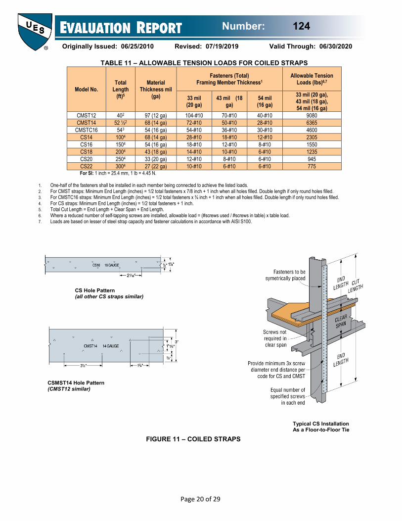
TABLE 11 – ALLOWABLE TENSION LOADS FOR COILED STRAPS
Model No. Total
Length (ft)5
Material Thickness mil
(ga)
Fasteners (Total) Framing Member Thickness1
Allowable Tension Loads (lbs)6,7
33 mil (20 ga)
43 mil (18 ga)
54 mil (16 ga)
33 mil (20 ga), 43 mil (18 ga), 54 mil (16 ga)
CMST12 402 97 (12 ga) 104-#10 70-#10 40-#10 9080 CMST14 52 ½2 68 (14 ga) 72-#10 50-#10 28-#10 6365
CMSTC16 543 54 (16 ga) 54-#10 36-#10 30-#10 4600 CS14 1004 68 (14 ga) 28-#10 18-#10 12-#10 2305 CS16 1504 54 (16 ga) 18-#10 12-#10 8-#10 1550 CS18 2004 43 (18 ga) 14-#10 10-#10 6-#10 1235 CS20 2504 33 (20 ga) 12-#10 8-#10 6-#10 945 CS22 3004 27 (22 ga) 10-#10 6-#10 6-#10 775 For SI: 1 inch = 25.4 mm, 1 lb = 4.45 N.
1. One-half of the fasteners shall be installed in each member being connected to achieve the listed loads. 2. For CMST straps: Minimum End Length (inches) = 1/2 total fasteners x 7/8 inch + 1 inch when all holes filled. Double length if only round holes filled. 3. For CMSTC16 straps: Minimum End Length (inches) = 1/2 total fasteners x ¾ inch + 1 inch when all holes filled. Double length if only round holes filled. 4. For CS straps: Minimum End Length (inches) = 1/2 total fasteners + 1 inch. 5. Total Cut Length = End Length + Clear Span + End Length. 6. Where a reduced number of self-tapping screws are installed, allowable load = (#screws used / #screws in table) x table load. 7. Loads are based on lesser of steel strap capacity and fastener calculations in accordance with AISI S100.
CS Hole Pattern (all other CS straps similar)
CSMST14 Hole Pattern (CMST12 similar)
Typical CS Installation As a Floor-to-Floor Tie FIGURE 11 – COILED STRAPS
Number: 124
Originally Issued: 06/25/2010 Revised: 07/19/2019 Valid Through: 06/30/2020
Page 21 of 29
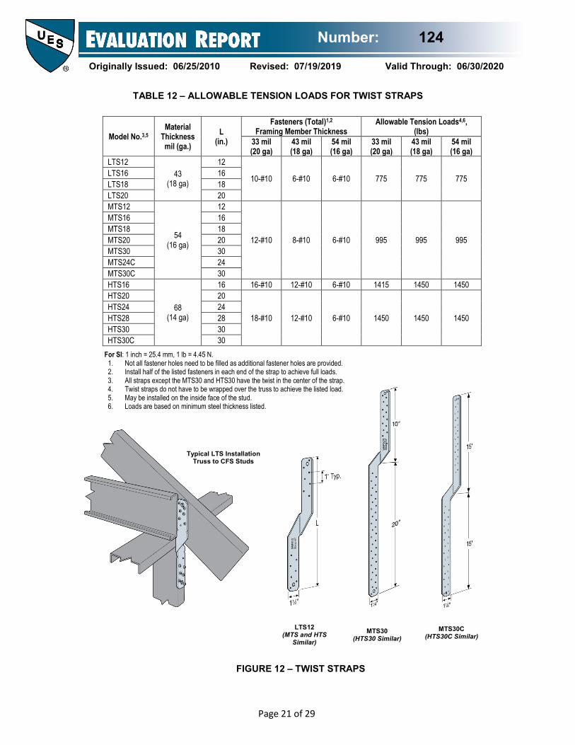
For SI: 1 inch = 25.4 mm, 1 lb = 4.45 N. 1. Not all fastener holes need to be filled as additional fastener holes are provided. 2. Install half of the listed fasteners in each end of the strap to achieve full loads. 3. All straps except the MTS30 and HTS30 have the twist in the center of the strap. 4. Twist straps do not have to be wrapped over the truss to achieve the listed load. 5. May be installed on the inside face of the stud. 6. Loads are based on minimum steel thickness listed.
Model No.3,5 Material
Thickness mil (ga.)
L (in.)
Fasteners (Total)1,2
Framing Member Thickness Allowable Tension Loads4,6,
(lbs) 33 mil (20 ga)
43 mil (18 ga)
54 mil (16 ga)
33 mil (20 ga)
43 mil (18 ga)
54 mil (16 ga)
LTS12 43
(18 ga)
12
10-#10 6-#10 6-#10 775 775 775 LTS16 16 LTS18 18 LTS20 20 MTS12
54 (16 ga)
12
12-#10 8-#10 6-#10 995 995 995
MTS16 16 MTS18 18 MTS20 20 MTS30 30 MTS24C 24 MTS30C 30 HTS16
68 (14 ga)
16 16-#10 12-#10 6-#10 1415 1450 1450 HTS20 20
18-#10 12-#10 6-#10 1450 1450 1450 HTS24 24 HTS28 28 HTS30 30 HTS30C 30
LTS12 (MTS and HTS
Similar)
MTS30 (HTS30 Similar)
MTS30C (HTS30C Similar)
FIGURE 12 – TWIST STRAPS
Typical LTS Installation Truss to CFS Studs
TABLE 12 – ALLOWABLE TENSION LOADS FOR TWIST STRAPS
Number: 124
Originally Issued: 06/25/2010 Revised: 07/19/2019 Valid Through: 06/30/2020
Page 22 of 29
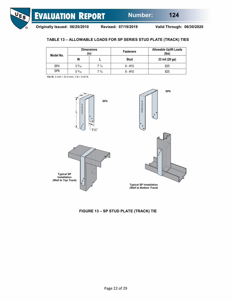
For SI: 1 inch = 25.4 mm, 1 lb = 4.45 N.
Model No. Dimensions
(in) Fasteners Allowable Uplift Loads (lbs)
W L Stud 33 mil (20 ga)
SP4 3 9/16 7 1/4 6 - #10 825 SP6 5 9/16 7 3/4 6 - #10 825
FIGURE 13 – SP STUD PLATE (TRACK) TIE
SP6
SP4
Typical SP Installation
(Wall to Top Track) Typical SP Installation
(Wall to Bottom Track)
TABLE 13 – ALLOWABLE LOADS FOR SP SERIES STUD PLATE (TRACK) TIES
Number: 124
Originally Issued: 06/25/2010 Revised: 07/19/2019 Valid Through: 06/30/2020
Page 23 of 29
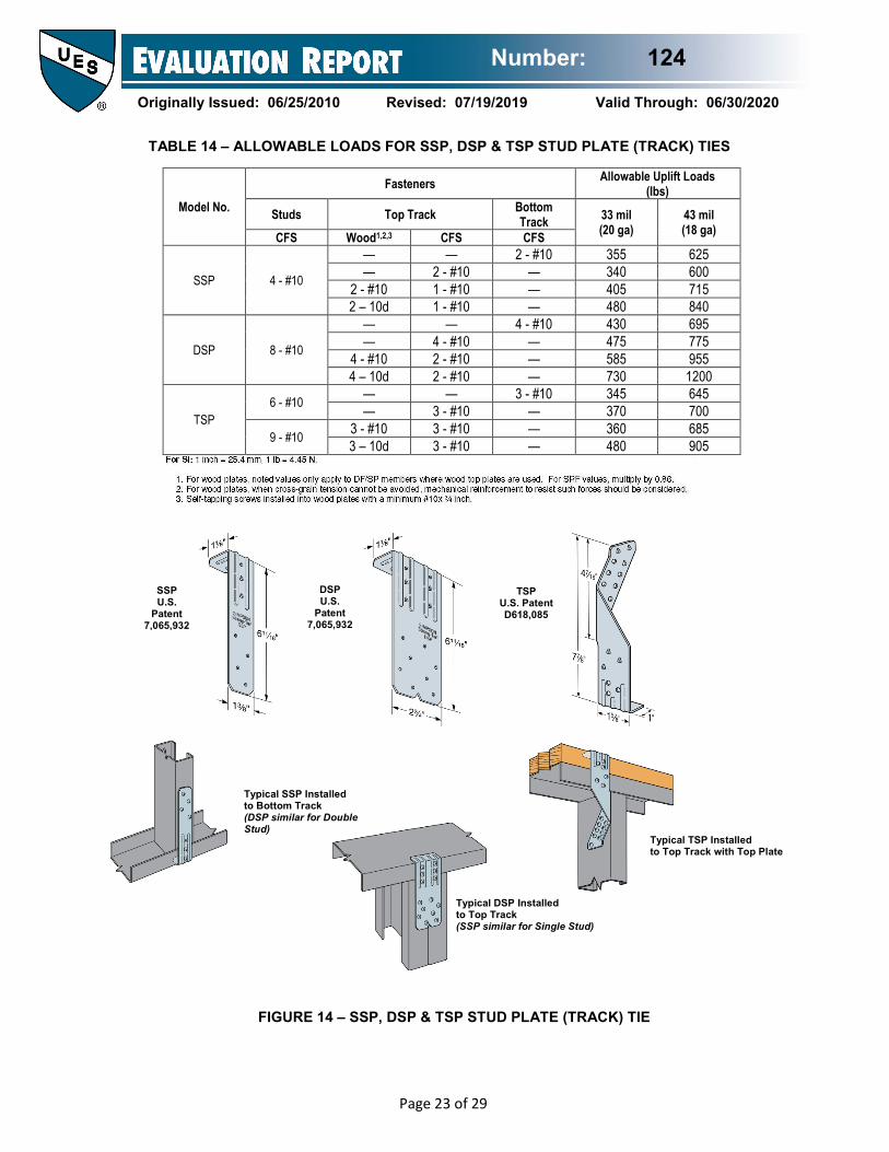
Model No.
Fasteners Allowable Uplift Loads (lbs)
Studs Top Track Bottom Track 33 mil
(20 ga) 43 mil (18 ga) CFS Wood1,2,3 CFS CFS
SSP 4 - #10
— — 2 - #10 355 625 — 2 - #10 — 340 600
2 - #10 1 - #10 — 405 715 2 – 10d 1 - #10 — 480 840
DSP 8 - #10
— — 4 - #10 430 695 — 4 - #10 — 475 775
4 - #10 2 - #10 — 585 955 4 – 10d 2 - #10 — 730 1200
TSP 6 - #10 — — 3 - #10 345 645
— 3 - #10 — 370 700
9 - #10 3 - #10 3 - #10 — 360 685 3 – 10d 3 - #10 — 480 905
SSP U.S.
Patent 7,065,932
DSP U.S.
Patent 7,065,932
TSP U.S. Patent D618,085
Typical SSP Installed to Bottom Track (DSP similar for Double Stud) Typical TSP Installed
to Top Track with Top Plate
Typical DSP Installed to Top Track (SSP similar for Single Stud)
FIGURE 14 – SSP, DSP & TSP STUD PLATE (TRACK) TIE
TABLE 14 – ALLOWABLE LOADS FOR SSP, DSP & TSP STUD PLATE (TRACK) TIES
Number: 124
Originally Issued: 06/25/2010 Revised: 07/19/2019 Valid Through: 06/30/2020
Page 24 of 29
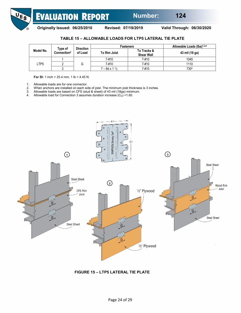
For SI: 1 inch = 25.4 mm, 1 lb = 4.45 N.
1. Allowable loads are for one connector. 2. When anchors are installed on each side of joist. The minimum joist thickness is 3 inches. 3. Allowable loads are based on CFS (stud & sheet) of 43 mil (18ga) minimum. 4. Allowable load for Connection 3 assumes duration increase (CD) =1.60.
Model No. Type of Connection2
Direction of Load
Fasteners Allowable Loads (lbs)1,3,4
To Rim Joist To Tracks & Shear Wall 43 mil (18 ga)
LTP5 1
G 7-#10 7-#10 1045
2 7-#10 7-#10 1110 3 7 – 8d x 1 1/2 7-#10 7304
3 1
2
FIGURE 15 – LTP5 LATERAL TIE PLATE
TABLE 15 – ALLOWABLE LOADS FOR LTP5 LATERAL TIE PLATE
Number: 124
Originally Issued: 06/25/2010 Revised: 07/19/2019 Valid Through: 06/30/2020
Page 25 of 29
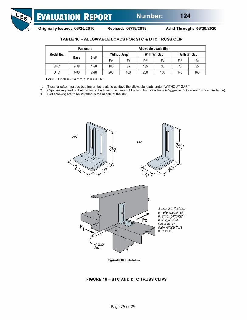
For SI: 1 inch = 25.4 mm, 1 lb = 4.45 N.
1. Truss or rafter must be bearing on top plate to achieve the allowable loads under “WITHOUT GAP.” 2. Clips are required on both sides of the truss to achieve F1 loads in both directions (stagger parts to aboutd screw interfence). 3. Slot screw(s) are to be installed in the middle of the slot.
Model No. Fasteners Allowable Loads (lbs)
Base Slot3 Without Gap1 With 1/4” Gap With ½” Gap
F12 F2 F12 F2 F12 F2 STC 2-#8 1-#8 185 35 135 35 75 35 DTC 4-#8 2-#8 200 160 200 160 145 160
DTC
FIGURE 16 – STC AND DTC TRUSS CLIPS
STC
Typical STC Installation
TABLE 16 – ALLOWABLE LOADS FOR STC & DTC TRUSS CLIP
Number: 124
Originally Issued: 06/25/2010 Revised: 07/19/2019 Valid Through: 06/30/2020
Page 26 of 29
TABLE 17 – ALLOWABLE TORSIONAL MOMENT, BRACE STRENGTH AND BRACE STIFFNESS FOR LSUBH, SUBH AND MSUBH SERIES CONNECTORS
Model No.
Stud Depth
(in.)
Stud Thickness mils (ga.)
Laterally Loaded C-Stud1 Axially Loaded C-Stud1
Allowable Torsional Moment 2
(in. - lbs)
Allowable Brace Strength 2
(lbs.) Brace Stiffness 3
(lbs. /in.)
Min Max Min Max Min Max
LSUBH3.25 3.625 33 (20) 215 330 155 275 2300 2685 43 (18) 230 370 175 310 5075 7585 54 (16) 225 370 195 345 5075 8100
SUBH3.25 3.625 20 (33) 320 345 230 370 1450 1985 18 (43) 355 430 255 420 2780 4035 16 (54) 420 455 290 475 2925 3975
MSUBH3.25 3.625 16 (54) 550 800 435 630 3440 4015 14 (68) 640 860 485 695 4040 6145 12 (97) 670 860 515 770 6860 14265
LSUBH3.25 6.00 33 (20) 225 330 120 140 870 730 43 (18) 250 395 155 285 1010 2075 54 (16) 265 395 180 330 1025 2565
SUBH3.25 6.00 20 (33) 275 385 110 110 605 605 18 (43) 295 525 230 250 1050 1205 16 (54) 350 550 275 415 1130 1700
MSUBH3.25 6.00 16 (54) 565 895 385 430 1630 1695 14 (68) 655 925 455 620 1860 2655 12 (97) 690 960 505 765 4070 4090
LSUBH3.25 8.00 43 (18) 235 375 135 135 815 815 54 (16) 250 375 180 260 1130 1130
SUBH3.25 8.00 18 (43) 255 570 190 190 505 535 16 (54) 325 605 250 300 895 1025
MSUBH3.25 8.00 17 (54) 545 890 270 270 1025 1045 14 (68) 635 925 435 455 1400 1400 12 (97) 665 955 545 545 2465 2465
For SI: 1 inch = 25.4 mm, 1lb = 4.45N. 1. To obtain allowable loads tabulated for “Min.” fasteners, a screw shall be placed in each pre-punch round hole (1 screw total). For allowable loads tabulated for “Max.”
fastener, a screw shall be placed in each of the pre-punch round and triangle holes (2 screws total). 2. Allowable loads are for use when utilizing the Allowable Strength Design (ASD) methodology. For LRFD loads the ASD tabulated values shall be multiplied by 1.6. 3. Tabulated values apply to both ASD and LRFD designs.
FIGURE 17 – LSUBH/SUBH MSUBH CONNECTORS
SUBH3.25 U.S.
Patent 8,813,456
Number: 124
Originally Issued: 06/25/2010 Revised: 07/19/2019 Valid Through: 06/30/2020
Page 27 of 29
TABLE 18--CONNECTOR MATERIAL PROPERTIES TABLE
Model No. / Model Series ASTM Specification
Minimum Yield
Strength Fy (ksi)
Minimum Tensile
Strength Fu (ksi)
Nominal Thickness
Min. Base Metal
Thickness (inch)
S/HDB (Base Plate) A36 33 52 ½ inch 0.485 S/HD8B & 10B (Body) A 1011 Grade 40 40 55 10 GA. 0.126 S/HD15B (Body) A 1011 Grade 40 40 55 7 GA. 0.171 S/HDS (Base Plate) A36 33 52 ½ inch 0.485 S/HD8S & 10S (Body) A 1011 Grade 40 40 55 10 GA. 0.126 S/HD15S (Body) A 1011 Grade 40 40 55 7 GA. 0.171 S/HDU (Washer) A 1011 Grade 33 33 52 3 GA. 0.229 S/HDU (Body) A 653 SS GR 33 33 45 10 GA. 0.129 S/LTT (Body) A 653 SS GR 33 33 45 12 GA. 0.099 S/LTT (Base) A 1011 Grade 33 33 52 3 GA. 0.229 S/DTT2Z A 653 SS GR 33 33 45 14 GA. 0.070 S/HTT, HTT A 653 SS GR 33 33 45 11 GA. 0.112 S/BA A 653 SS GR 33 33 45 14 GA. 0.070 S/B A 653 SS GR 33 33 45 12 GA. 0.099 S/LBV A 653 SS GR 33 33 45 14 GA. 0.070 S/HJCT A 653 SS GR 40 42 56 12 GA. 0.099 S/JCT A 653 SS GR 40 40 55 14 GA. 0.070 TJC37 A 653 SS GR 33 33 45 16 GA. 0.057 TBD22 A 653 SS GR 40 40 55 22 GA. 0.029 S/H1A A 653 SS GR 33 33 45 18 GA. 0.046 LSTA12, 15, 18, 21, 24 A 653 SS GR 50 CL1 50 65 20 GA. 0.035 LSTA30 & LSTA36 A 653 SS GR 50 CL1 50 65 18 GA. 0.046 MSTA9, 12, 15, 18, 21, 24, A 653 SS GR 50 CL1 50 65 18 GA. 0.046 MSTA30, 36, 49 A 653 SS GR 50 CL1 50 65 16 GA. 0.057 MSTC28, 40, 52 A 653 SS GR 50 CL1 50 65 16 GA. 0.057 S/MST27, 37 A 653 SS GR 40 40 55 12 GA. 0.099 S/MST48 A 653 SS GR 40 42 56 12 GA. 0.099 S/MST60, 72 A 653 SS GR 40 42 56 10 GA. 0.129 LSTI A 653 SS GR 40 40 55 18 GA. 0.046 MSTI A 653 SS GR 40 40 55 12 GA. 0.099 ST9, ST12, ST18, ST22 A 653 SS GR 33 33 45 16 GA. 0.057 ST6215 A 653 SS GR 33 33 45 16 GA. 0.057 ST6224 A 653 SS GR 40 40 55 16 GA. 0.057 ST2115 A 653 SS GR 50 CL1 50 65 20 GA. 0.035 ST2122 A 653 SS GR 40 40 55 20 GA. 0.035 ST2215 A 653 SS GR 50 CL1 50 65 20 GA. 0.035 ST292 A 653 SS GR 33 33 45 20 GA. 0.035 ST6236 A 653 SS GR 50 CL1 50 65 14 GA. 0.070 FHA A 653 SS GR 33 33 45 12 GA. 0.099 HRS A 653 SS GR 33 33 45 12 GA. 0.099 CMST12 A 653 SS GR 50 CL1 50 65 12 GA. 0.099 CMST14 A 653 SS GR 50 CL1 50 65 14 GA. 0.070
Number: 124
Originally Issued: 06/25/2010 Revised: 07/19/2019 Valid Through: 06/30/2020
Page 28 of 29
TABLE 18- CONNECTOR MATERIAL PROPERTIES TABLE (CONT.)
CMSTC16 A 653 SS GR 50 CL1 50 65 16 GA. 0.057 CS14 A 653 SS GR 50 CL1 50 65 14 GA. 0.070 CS16 A 653 SS GR 40 40 55 16 GA. 0.057 CS18 A 653 SS GR 40 40 55 18 GA. 0.046 CS20 A 653 SS GR 40 40 55 20 GA. 0.035 CS22 A 653 SS GR 40 40 55 22 GA. 0.029 LTS A 653 SS GR 33 33 45 18 GA. 0.046 MTS, MTSC A 653 SS GR 33 33 45 16 GA. 0.057 HTS, HTSC A 653 SS GR 40 40 55 14 GA. 0.070 SP A 653 SS GR 33 33 45 20 GA. 0.035 SSP A 653SS GR 40 40 55 18 GA. 0.046 DSP A 653SS GR 40 40 55 18 GA. 0.046 TSP A 653SS GR 40 40 55 16 GA. 0.057 LTP5 A 653SS GR 40 40 55 20 GA. 0.035 DTC A 653 SS GR 33 33 45 18 GA. 0.046 STC A 653 SS GR 33 33 45 18 GA. 0.046 LSUBH A 653SS GR 40 40 55 20 GA. 0.035 SUBH A 653 SS GR 40 40 55 18 GA. 0.046 MSUBH A 653 SS GR 40 40 55 14 GA. 0.070
For SI: 1 inch = 25.4 mm, 1 psi = 6.895 kPa.

Number: 124
Originally Issued: 06/25/2010 Revised: 07/19/2019 Valid Through: 06/30/2020
Page 29 of 29
CITY OF LOS ANGELES SUPPLEMENT Simpson Strong-Tie Company Inc. 5956 West Las Positas Boulevard Pleasanton, California 94588 (800) 999-5099 www.strongtie.com SIMPSON STRONG-TIE CONNECTORS FOR COLD-FORMED STEEL CONSTRUCTION CSI Division:
05—METALS CSI Section:
05 05 23—Metal Fastenings 1.0 RECOGNITION Simpson Strong-Tie connectors for cold-formed steel construction in IAPMO UES ER-124 are acceptable alternatives to what is specified in the following codes and regulations: • 2017 City of Los Angeles Building Code (LABC) 2017
City of Los Angeles Residential Code (LARC) 2.0 LIMITATIONS 2.1 References in IAPMO UES ER-124 to section numbers of the 2015 IBC and 2015 IRC are the same section numbers in the LABC and LARC, as applicable. 2.2 Hold-down connectors designed to resist shear wall overturning moments shall be reduced to 75 percent of the allowable load values shown in Tables 1A,1B, 2 and 3 of ER-124, in accordance with LABC Section 2305.5. 2.3 Engineered designs submitted in accordance with LARC Section R301.1.3 shall also comply with LARC Section R301.1.3.1. 2.4 Design, installation and inspection shall be in accordance with Chapters 16 and 17 of the LABC, as applicable.
2.5 Calculations verifying compliance with the allowable load tables in ER-124 shall be submitted to the Structural Plan Check Division at the time of permit application. The calculations shall be prepared by a Civil or Structural Engineer registered in the State of California. 2.6. The wall anchorage assembly to a cold-formed steel framed flexible diaphragm in the repair, retrofit and new construction of tilt up and masonry wall anchorage is outside the scope of this supplement.
For additional information about this evaluation report please visit www.uniform-es.org or email at [email protected]