Null test optics for the MMT and Magellan 6.5-rn f/1.25 ... Proc...Null test optics for the MMT and...
12
Null test optics for the MMT and Magellan 6.5-rn f/1.25 primary mirrors J. H. Burge, D. S. Anderson, D. A. Ketelsen, and S. C. West Steward Observatory Mirror Lab University of Arizona Tucson, Arizona 85721 ABSTRACT The instruments used to interferometrically measure the optical surfaces of the 6.5-rn f/i .25 prirnaiy rnirrors for the MMT conversion and Magellan Telescopes rnust compensate over 800 un surface departure frorn the best fitting sphere. The errors in the optical test rnust not contribute rnore than 0.04 arc seconds FWHM to the final image and the conic constant rnust be held to 0.01%. This paper presents the design, analysis, fabrication, and certifica- tion ofthe instruments used to measure these giant rnirrors to such high accuracy. 1. INTRODUCTION Prirnary rnirrors for rnodern telescopes are tested interferometrically frorn the center of curvature using null correctors (see Fig. 1). The null corrector, or null lens, compensates for the asphericity of the mirror surface. Interferornetric testing with a null lens allows an accurate, high-resolution rneasurernent of the entire surface that can be made in several rninutes. Two instru- ments are being built for interferornetric rneasurements of the 6.5-rn nürrors at the Steward Observatoiy Mirror Lab (SOML). An infrared interferorneter with a germanium and ZnSe null corrector will test the ground surface to rnonitor loose-abrasive grinding. The polished sur- face will be rneasured with green laser light using a Shack cube inter- ferorneter co-aligned with a BK7 null corrector. Both the infrared and visible systerns have been carefully designed to give excellent perfonn- ance in terms of wavefront correction, alignment sensitivity, imaging of the mirror to the detector, diffraction effects, ghost reflections, and ease of use. The lenses for these instruments are fabricated and meas- ured precisely. The accurate alignment and stable support of these lenses require a well designed and constructed mechanical system. The mounting and alignment methods used for the new null correctors fol- low from the experience of building similar, smaller instruments at Steward Observatoiy.' PRIMARY An optical test for measuring null correctors has been developed that MIRROR uses a rotationally symmetric computer-generated hologram (CGH) to synthesize the wavefront that would be reflected by a perfect pnmaiy Figure 1. Schematic drawing of null test. mirror. The test of a null lens is performed by measuring the CGH through the null corrector. Since the CGH is made independently from the null corrector, agreement between the null lens and the CGH indicate that both the null lens and the CGH are correct. This test is planned for both null correctors for the 6.5-m mirrors. 658 / SPIE Vol. 2199 O-8194-1494-8194/$6.00 INTERFEROMETER WITH NULL CORRFCTOR LASER LIGHT
Transcript of Null test optics for the MMT and Magellan 6.5-rn f/1.25 ... Proc...Null test optics for the MMT and...
Null test optics for the MMT and Magellan 6.5-rn f/1.25 primary mirrors
J. H. Burge, D. S. Anderson, D. A. Ketelsen, and S. C. West
Steward Observatory Mirror LabUniversity of Arizona
Tucson, Arizona 85721
ABSTRACTThe instruments used to interferometrically measure the optical surfaces of the 6.5-rn f/i .25prirnaiy rnirrors for the MMT conversion and Magellan Telescopes rnust compensate over800 un surface departure frorn the best fitting sphere. The errors in the optical test rnust notcontribute rnore than 0.04 arc seconds FWHM to the final image and the conic constantrnust be held to 0.01%. This paper presents the design, analysis, fabrication, and certifica-tion ofthe instruments used to measure these giant rnirrors to such high accuracy.
1. INTRODUCTION
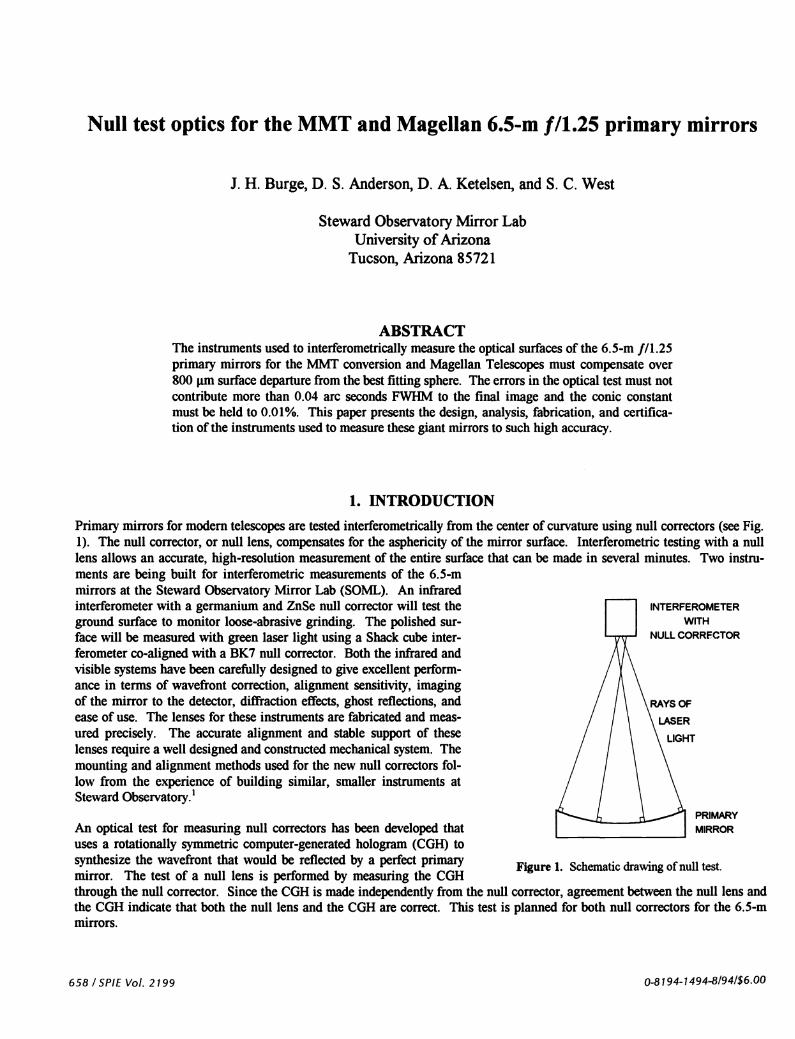
Prirnary rnirrors for rnodern telescopes are tested interferometrically frorn the center of curvature using null correctors (see Fig.1). The null corrector, or null lens, compensates for the asphericity of the mirror surface. Interferornetric testing with a nulllens allows an accurate, high-resolution rneasurernent of the entire surface that can be made in several rninutes. Two instru-ments are being built for interferornetric rneasurements of the 6.5-rnnürrors at the Steward Observatoiy Mirror Lab (SOML). An infraredinterferorneter with a germanium and ZnSe null corrector will test theground surface to rnonitor loose-abrasive grinding. The polished sur-face will be rneasured with green laser light using a Shack cube inter-ferorneter co-aligned with a BK7 null corrector. Both the infrared andvisible systerns have been carefully designed to give excellent perfonn-ance in terms of wavefront correction, alignment sensitivity, imagingof the mirror to the detector, diffraction effects, ghost reflections, andease of use. The lenses for these instruments are fabricated and meas-ured precisely. The accurate alignment and stable support of theselenses require a well designed and constructed mechanical system. Themounting and alignment methods used for the new null correctors fol-low from the experience of building similar, smaller instruments atSteward Observatoiy.'
PRIMARY
An optical test for measuring null correctors has been developed that MIRROR
uses a rotationally symmetric computer-generated hologram (CGH) tosynthesize the wavefront that would be reflected by a perfect pnmaiy Figure 1. Schematic drawing of null test.mirror. The test of a null lens is performed by measuring the CGHthrough the null corrector. Since the CGH is made independently from the null corrector, agreement between the null lens andthe CGH indicate that both the null lens and the CGH are correct. This test is planned for both null correctors for the 6.5-mmirrors.
658 / SPIE Vol. 2199 O-8194-1494-8194/$6.00
INTERFEROMETER
WITH
NULL CORRFCTOR
LASER
LIGHT

2. INTERFEROMETRIC METROLOGY USING NULL CORRECTORS
2. 1 DESCRIPTION OF NULL TESTThe interferometric null test uses interference between light that has been reflected from the mirror, and light from a referencesurface. The interferometer creates a spherical wavefront of laser light that is split into a reference and a test beam. The testbeam travels through the null corrector, reflects off the mirror under test, and travels back through the null corrector into theinterferometer. The test is autostigmatic -- the light retraces its path to form a point image coincident with the source point.The reference beam is reflected off a high-quality spherical or piano surface. The test beam is recombined with the referencebeam causing an interference fringe pattern that corresponds to the difference between the two wavefronts. The fringe pattern isimaged onto a detector for analysis. By simultaneously shifting the reference beam and measuring the change in intensity ateach pixel ofthe image, the phase difference, which is proportional to the surface error of the mirror, is calculated at each sam-pled location.
The null corrector is designed to modify the spherical wavefront from the interferometer to produce a wavefront that matchesthe desired aspheric shape of the mirror. Ifboth the null lens and the mirror are perfect, this test wavefront will exactly matchthe reference wavefront. The resulting interference pattern will show no variation, giving a "null" result (no surface error). Ifthe mirror does have figure errors, they will be imparted to the reflected wavefront and show up in the interference pattern. Er-rors in the reflected wavefront are exactly twice the size of the errors in the mirror. It is important to note that any error in thenull corrector will cause a shape change in the test wavefront that will be interpreted as a figure error in the mirror. The nulltest simply measures how well the mirror fits the templatecreated by the null corrector. It requires additional testing todetermine the absolute accuracy ofthis template. Couder 2 S
(1927)I
Of the several types of null correctors shown in Fig. 2, theOffner null lens is most commonly used for large modemprimary mirrors because it allows the measurement of fastprimaries to high accuracy and with reasonable manufac- 3turing tolerances. This null corrector consists of a large relay Dali
I
lens and a smaller field lens. The design principle of the nullcorrector uses the field lens to image the primary mirror ontothe relay lens. The power and shape of the relay lens are cho-sen to introduce spherical aberration that compensates theasphericity of the primary mirror. The optimization of the 4two-element Offlier null corrector is discussed by Offner5, F • I
Holleran6 Puiyaev and Shandin7 , Moya and Landgrave8 , (
Sasian9 .' o&' , Offner and Malacara'2 , and Shafer'3.
The design ofthe null test requires more than an accurate null Offnercorrector. The instruments are complex optical systems with (1)illumination, wavefront correction, and imaging optics. Thewavefrontcorrectionisperformedbythenulllens. Theillu- 5,1 -— -—-—-
. mination optics project a laser beam through a spatial filter toRELAY LENS FIELD LENS
give a well-conditioned wavefront. The imaging optics proj.ect the interference pattern as a scaled image of the primaiymirror onto the detector plane. Figure 2. Types of refractive null correctors used for
testing primal)' mirr23'5 These drawings are sche-2.2 IMAGiNG REQUIREMENTS tic d not to scale.During grinding and polishing, the data from the infrared andvisible interferometers are used to direct the figuring. It is important to minimize the mapping distortion of the mirror throughthe null lens. The imaging distortion causes two problems in the data analysis; it causes small surface defects to appear shiftedradially and it re-maps low order errors from alignment (focus, and coma) into higher order errors. A discussion of interfer-ometric measurement errors introduced by small amounts of distortion is given by Selberg'4 and the details of the effects of
SPIEVo!. 2199/659

distortion in the null test are given by Burge'. The infrared null lens was designed to have minimal mapping error and thevisible system uses relay optics to correct the distortion introduced by the null lens.
Improper imaging causes diffraction "ripples" in the measured phase and causes the edge of the mirror to appear flawed. Thiseffect, and other errors from diffraction, are minimized by focusing the mirror onto the detector array. Both of the interferome-ters use apertures at intennediate images of the primaiy to help define the focus. Also, a rotating ground glass disk correctlypositioned in the visible system eliminates Fresnel noise, which is caused by scatter of the coherent laser light from dust on thelens surfaces. Both null correctors were designed to avoid ghost reflections that can cause troublesome spurious fringes.
2.3 ALIGNMENT OF TEST OPTICS WITh PRIMARY MIRRORSince this is an autostigmatic test, the shape ofthe wavefront created by the null corrector defines the shape of the mirror. For agiven null lens and spacing to the primaiy mirror, the shape of the mirror is fully determined by the shape of the wavefront. It iseasy in practice to align the null lens with respect to the mirror because the different alignment degrees of freedom cause dis-tinct changes in the interference pattern. To find the correct null lens position and orientation with respect to the mirror, thenull lens is first positioned approximately to get the light to reach the detector. Fine adjustments are made to eliminate thefringes oftilt, focus and coma. Interferograms of these characteristic aberrations are shown in Fig. 3. Lateral translation of thenull lens causes straight tilt fringes in the interferogram. Vertical translation along the axis causes focus in the interferogram.Rotation ofthe null corrector about the paraxial center of curvature causes coma in the interferogram. Since it is easy to differ-entiate tilt, coma, and focus in an interferogram by inspection, the alignment is done quickly and easily.
TILT FOCUS X COMA Y COMA
A small amount of residual alignment error always exists and must be removed in the data analysis. About a tenth of a fringe oftilt, focus, or coma often remains after alignment. Any small mechanical instabilities will also cause small variations of theseaberrations. Since tilt, focus, or coma measured in the mirror comes from test misalignment and because these aberrations donot affect the telescope operation, they are always removed in the data analysis. These low-order terms are easily removed byfirst fitting Zernike polynomials to the raw data and then subtracting the appropriate terms from the data.
A tolerance is imposed on the primary radius of curvature to insure that the null lens is used at the correct distance from theprimary mirror. The null corrector creates a wavefront that propagates to fit the desired shape of the mirror. Since the wave-front changes as it propagates, there is a family of different surfaces that will give a null test, only one of which has the desiredshape. Each member of the family can be described to fourth-order in radial position rby specifying a radius of curvature R andconic constant K. In practice, the null lens is moved axially to eliminate power in the reflected wavefront. The distance atwhich this condition is satisfied depends on R. Therefore the conic constant of the surface matching the wavefront depends onR. The change in K is related to the change in R by
AK AR (1)
K
660/SPIE Vol. 2199
Figure 3. Interferograms showing alignment errors of tilt, focus, and coma. Some tilt has been added to the focus and coma.

The radius of curvature R is inferred from a direct measurement of the distance between the null corrector and the primary mir-ror. The optician monitors this distance and designs the grinding and polishing strokes to keep the radius within tolerance.
The null test is also insensitive to optical surface decentration and tilt with respect to the axis defined by the null corrector.These pose no real problem as long as the decentration and wedge of the optical surface with respect to the 6.5-m blank are lessthan 1 nun, which can be accommodated in the telescope. The wedge is measured by rotating the mirror about the mechanicalreference axis, and measuring runout in the optical surface. The decentration is determined from the amount of coma seen inthe null test when the mirror is rotated about is mechanical axis. The centration and wedge of the optical surface are largelydetermined during generating. Since little material is removed during grinding and polishing, only small changes are made inthe mechanical properties ofthe mirrors.
2.4. ENVIRONMENTAL EFFECTSSince the measurements of the optical surfaces are performed using instruments many meters away, environmental effects cancause significant errors. Variations in air density can cause both random and systematic errors. Motion of the interferometer orthe mirror due to vibration makes phase shifting interferometry difficult and introduces random errors in the measurement. Therandom errors are reduced to an acceptable level by averaging many measurements, but systematic errors remain and degradethe test accuracy.
The random testing errors are minimized by the design of the test facility and further reduced by averaging. Vibration and airmotion (seeing) are the dominant sources of random variations in the testing of large optics. These errors are kept as small aspossible by using a large, well-controlled lab and vibration-isolated test tower. The remaining random measurement errors arereduced by averaging large numbers of measurements. The error in the average due to the random, uncorrelated effects de-creases as the square root of the number of measurements in the average.
Measurement errors due to vibration are minimizedby using an isolated test tower, short integrationtimes, and testing on a null fringe. The testing ofprimaiy mirrors at Steward Observatory is per-formed on a rigid test tower that is isolated fromground vibrations by pneumatic supports (see Fig.4). This test tower is 24 meters tall and weighs 400tons. It moves as a rigid body with a resonance ofabout 1.2 Hz, and lowest internal mode is at 9.5Hz. The tower isolation reduces the vibrationproblem to a level that allows phase shifting inter-ferometry, although with some difficulty. The useof a shuttered CCD camera that captures imagesusing very short exposures freezes out fringe vibra-tion during each frame. However, the relative mo-tion between the mirror and the interferometer be-tween frames introduces a measurement error. Theerror in the phase computation due to vibration isroughly proportional to the spatial phase variationof the surface under test. For a good surface withthe system aligned on null fringe, the test surfaceshows very little spatial variation so the effects ofvibration are minimized. A great attribute of thenull test is that the testing becomes more accurateas the figure of the mirror improves.
Figure 4. Isolated test tower at Steward Observatory Mirror Lab. Theentire 400-ton concrete and steel structure is supported by 40 air-filledisolators. Drawing by E. Anderson.
SIDE VIEW PNUEMATICSUPPORT
FRONT VIEW
The atmospheric seeing, or wavefront distortiondue to air motion, causes random errors in the surface measurement. Air has refractive index variations proportional to density,thus temperature fluctuations. If a mass of cold, dense air floats over the mirror during a test, the test wavefront will be dis-
SPIE Vol. 2199/661

torted and the measurement of the surface will indicate a low area on the mirror. The tendency to form these air masses isminimized by using a large lab with well-mixed air and minimal heat (or cold) loading. Eliminating the seeing problem byperfonning the test in a vacuum hambe5"6 would be extremely expensive and difficult to implement for large mirrors.
An important point demonstrated by Martin et is that the random testing errors are distributed where the mirror specifica-tion has room for them. The mirror specification allows larger errors at low spatial frequency than high frequency. The ran-dom testing errors tend to have mainly low frequency variation while the final mirror surface has very little large-scale varia-tion. The combination ofthe surface errors at small scales and the measurement errors at large scales easily meets the telescoperequirements.
The random seeing averages out, but there may also be systematic density variations that would lead to erroneous measure-ments. Once the air handlers in the room are turned off, any warm air rises creating a stable vertical gradient. Also, a heatsource on one side ofthe room will cause a stable horizontal density gradient. The effect of the horizontal gradient is measuredby rotating the mirror, but there is no such test for the vertical gradient.
The vertical stratification of the air causes a focal length change and a small amount of spherical aberration or change in conicconstant. To quantify the effect of a vertical gradient, a computer simulation of the null test was performed, modeling the re-fractive index gradient of the air using discrete steps. The null test for the 6.5-rn /11.25 primary was simulated, setting thenumber of steps to be large enough that a further decrease in step size did not change the result. Assuming a perfect null cor-rector at the correct spacing, the resulting power and spherical aberration cause a change in the primaiy radius R and conic con-stant K of
AK -3.5•
(2)
R2where An total refractive index difference (mirror to null lens).
The temperature at SOML was measured to have a variation of about 0.5° C from the tower to the shop floor. Since the refrac-tive index of air changes by l.Ox 1O per °C'8 , the temperature gradient at SOML causes a conic constant error of less than 2ppm (pails-per-million) and a radius error of less than 0.3 ppm. Even if this effect was several times more severe, it would re-main negligible compared to the null corrector uncertainty of 80 ppm.
A different thermal effect is possible where the deep dish formed by the fast primaiy mirror holds a stable layer of cool air. Aray-trace simulation ofthis effect leads to
iK —4iflAD (3)
iflR
where An is the refractive index of the air held in the mirror. This effect is minimized by allowing air to flow through the cen-ter hole ofthe mirror.
3. NULL CORRECTOR FOR FIGURE MEASUREMENTS USING INFRARED LIGHT
An infrared null corrector has been fabricated that uses germanium and ZnSe lenses with a single diamond-turned aspheric sur-face. The null corrector, shown in Fig. 5, consists of three lenses: an aspheric ZnSe diverger, a plano-convex germanium relaylens, and a piano-convex ZnSe field lens. The optical design uses the aspheric surface to give a near-perfect wavefront error of0.00 14 mis and mapping error less than 1.3%. The aspheric surface for this null corrector was diamond turned and measuredwith a profilometer. The surface deviates from the best-fit sphere by 160 pun and was determined to be correct to ptm. Thenull corrector will be mounted horizontally and aligned to the collimated output from a Twyman-Green interferometer. Theinterferometer uses a CO2 laser operating at 10.6 jim, a PZT-shifted reference mirror, and a pyroelectric vidicon detector.'9
662 ISPIE Vol. 2199

The relative alignment between the system and the primaiy mirror will be perfonned by translating the interferometernu11 cor-rector in three directions and steering the beam with a fold flat. The fold flat is positioned 2/3 of the distance from the paraxialto the marginal focus, so tilting the mirror causes a change in pure Zernike coma.
. LDIVERGER FIELD LENS5Ommdiam 80 mm diaml2mmthick l4mmthickZnSe ZnSebi-convex RELAY LENS
piano-convex(one asphere) 200 mm diam
28 mm thickGermaniumpiano-convex
Figure5. Infrared null corrector for the testing of a 6.5-rn 1/1.25 paraboloidal primary mirrors. This design is optimized
for wavefront correction, imaging distortion, alignment tolerances, and ghost reflections.
This null corrector was designed to give excellent imaging performance with no troublesome ghost reflections. In order toavoid the diffraction problems associated with infrared interferometry, the image of the primary mirror is carefully focused ontothe vidicon detector. To facilitate this, the null corrector creates a real image of the primary mirror veiy near the large relaylens, where a circular aperture will be accurately placed to provide a sharp aperture to define the focus. To minimize ghost re-flections, the null lens was designed to avoid surfaces with near-normal ray incidence.
The elements in this null lens are the smallest that will work when aligned to machine tolerances (±50 jun over 200 mm). Thelenses were carefully made free of wedge so that they can be mounted in a simple accurately machined cell for alignment andspacing. A thorough tolerance analysis of the system indicates that the null lens will contribute surface measurement errors of1 .5 tm mis. Most of this error is due to refractive index inhomogeneity of the large germanium lens. The uncertainty of theconic constant in this null lens due to the manufacturing tolerances is nearly meeting the final telescope specificationof±O.0001. We plan to check the quality ofthe entire null lens assembly with a computer-generated hologram.
4. NULL CORRECTOR FOR FIGURE MEASUREMENTS USING VISIBLE LIGHT
4. 1 OPTICAL DESIGNA visible null corrector with a sophisticated imaging system is beingbuilt for measuring the 6.5-rn //1.25 primary mirrors. The interfer-ometer uses a frequency doubled YAG laser operating at 532 nm, aPZT-shifted Shack cube interferometer, imaging optics, and shut-tered CCD detector. The Shack cube, null lens, and imaging opticswill be precisely aligned on a single rigid truss. The laser light willbe fed into the system through a single mode optical fiber.
The Shack cube interferometer2° is used because of its simplicity andease of alignment. The Shack cube, shown in Fig. 6, is fabricatedwith a small pinhole at the center of curvature of the reference sur-face. The mechanical alignment of the cube to the null correctorrequires only that this one spherical surface be in the correct place.The interferometer is phase shifted by driving the cube and objectivewith PZT actuators.2' The Shack cube and null corrector are easily
IR INTERFEROMETER
LI FLAT
TO PRIMARY MIRROR
LASER LIGHT
FOCUSING OBJECTIVE
BEAMSPLITTER
aperture
TO DETECTOR
SPHERICALTEST BEAM
Figure 6. The Shack cube mterferorneter.
SPIEVo!. 2199/663

integrated into a single rigid unit.
The null corrector shown in Fig. 7 consists of the Shack-cube and three BK7 lenses: a relay lens, and two field lenses. The op-tical design gives a wavefront error of 4 nm rms (Fig. 7) and maximum mapping error of almost 5%.The null corrector will bemounted vertically to precise tolerances using the method described by West et a!.22 The relative alignment between the systemand the mirror will be performed by translating the entire unit in three directions and rotating about two flex-pivot axes. As inthe IR test, the lateral rotation is performed about an axis 2/3 of the way from paraxial to marginal focus to decouple wavefronttilt from the alignment. The test alignment will be controlled from a remote testing station.
GROUND GLASS \
RELAY LENS270 mm diam57.3 mm thick
FIELD LENS I90 mm diam18 mm thick
FIELD LENS 264 mm diam14 mm thick
RESIDUAL WAVEFRONT OPD
PRIMARY MIRRORTO PRIMARY MIRROR
Figure 7. Optical layout ofthe visible null lens for 6.5-rn 1/1.25 primary mirrors with Shack cube mterferometer and dis..tortion-correctmg relay. The insets show the residual wavefront and the scale ofthe null lens with the 6.5-rn mirror.
The imaging distortion induced by the null lens is corrected with the relay optics that are shown in Fig. 7. A plot of the map-ping error is shown in Fig. 8. This two-lens relay not only corrects the mapping error, but it projects the image of the primaryto infinity. This allows the use of a standard zoom lens to re-image the pupil at varying magnification. The re-imaging systemconsists of a 6X zoom lens fixed to the CCD camera that is mounted on a tip-tilt stage. All of the controls will be operatedre-motely to allow the optician to magni1y the image and to look with increased resolution anywhere on the mirror. High resolu-tion (--6 mm pixels at the mirror) will then be attained for sub-aperture testing without increasing the array size.
664/SP1E Vol. 2199
LASER
SHACK CUBE
RELAY
ZOOM LENS
CCD
APERTURE
NULL LENS

aC3
1.0
Figure 8. Mapping error for the null lens for testing the 6.5-rn /11.25 primary rnirror.
4.2 FABRICATION OF VISIBLE NULL CORRECTORThe lenses, which are made from H5 quality BK7 glass (from Ohara and Schott), are being figured to high quality at StewardObservatory. The spherical surfaces are measured using phase shifting interferometiy and the radii are measured using aFizeau interferometer and lens bench. The lenses are fabricated and measured to a few microns, then the spacings are re-optimized based on the as-fabricated lens dimensions.
The fast surface of the relay lens is measured using a test plate with an interesting illumination scheme shown in Fig. 9. Theconcave test plate is measured using a Fizeau interferometer with an //0.6 diverger. The diverger reference surface quality isdetermined by measuring a precision ball at many rotation angles. The convex surface of the relay lens is then measured withthis test plate using the Fizeau and diverger only for illumination and imaging. An imaging element is fit to the relay lens withthe outer surface nearly concentric with the test plate. For the relay lens measurement, there are four nearly concentric surfaces.To avoid spurious fringes, the Fizeau reference and the imager surface are tilted and the reflections from these surfaces areblocked. The test plate is pushed and phase shifting interferometiy is used to allow a high resolution measurement.
a) Measurement of test plate b) Measurement of relay lens
Figure 9. Measurement of the fast convex surface on the relay lens using a test plate. a) The concave test plate is measured using a Fizeauinterferometer. b) The fast convex surface (3) is measured against the test plate (4). For this measurement, surfaces 1 and 2 are tilted so thereflections from these surfaces can be blocked.
SPIE Vol. 2199 /665
0.0 0.2 0.4 0.6 0.8normalizsd radial position
1FIz.au Intsrfsrom.trwith fF0.6 diverger
I
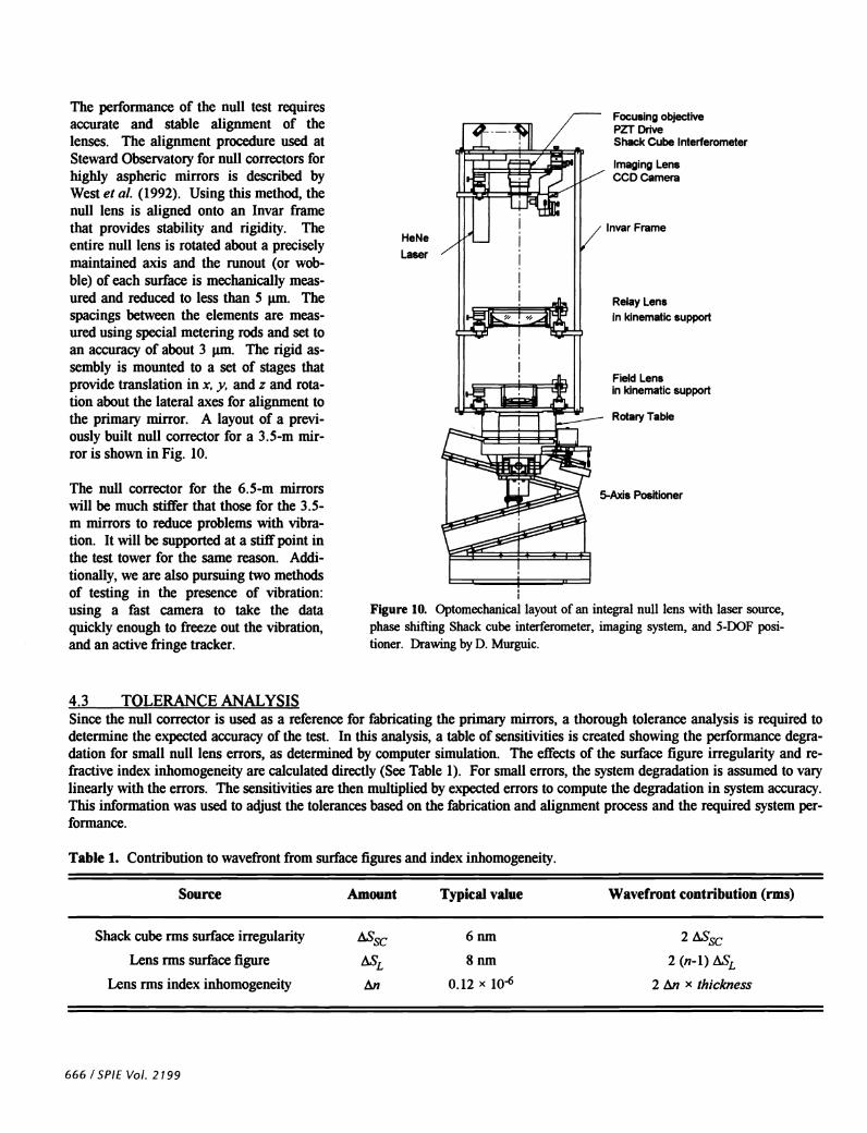
The perfonnance of the null test requiresaccurate and stable alignment of thelenses. The alignment procedure used atSteward Observatory for null correctors forhighly aspheric mirrors is described byWest et a!. (1992). Using this method, thenull lens is aligned onto an Invar framethat provides stability and rigidity. Theentire null lens is rotated about a preciselymaintained axis and the runout (or wob-ble) of each surface is mechanically meas-ured and reduced to less than 5 tm. Thespacings between the elements are meas-ured using special metering rods and set toan accuracy of about 3 tm. The rigid as-sembly is mounted to a set of stages thatprovide translation in x, y, and z and rota-tion about the lateral axes for alignment tothe pnmaiy mirror. A layout of a previ-ously built null corrector for a 3.5-rn mir-ror is shown in Fig. 10.
The null corrector for the 6.5-rn mirrorswill be much stiffer that those for the 3.5-m mirrors to reduce problems with vibra-tion. It will be supported at a stiff point inthe test tower for the same reason. Addi-tionally, we are also pursuing two methodsof testing in the presence of vibration:using a fast camera to take the dataquickly enough to freeze out the vibration,and an active fringe tracker.
Relay Lensin kinematic support
Field Lensin kinematic support
Rotary Table
4.3 TOLERANCE ANALYSISSince the null corrector is used as a reference for fabricating the primaiy mirrors, a thorough tolerance analysis is required todetermine the expected accuracy of the test. In this analysis, a table of sensitivities is created showing the performance degra-dation for small null lens errors, as determined by computer simulation. The effects of the surface figure irregularity and re-fractive index inhomogeneity are calculated directly (See Table 1). For small errors, the system degradation is assumed to vaiylinearly with the errors. The sensitivities are then multiplied by expected errors to compute the degradation in system accuracy.This information was used to adjust the tolerances based on the fabrication and alignment process and the required system per-formance.
Table 1. Contribution to wavefront from surface figures and index inhomogeneity
Source Amount Typical value Wavefront contribution (rms)
Shack cube rms surface irregularity ES 6 nm 2ESLens rms surface figure ESL 8 nm 2 (n-i) ESL
Lens nns index inhomogeneity i.n 0.12 x 10 2 Ln X thickness
666 ISPIE Vol. 2199
Focusing objectivePZT DriveShack Cube Interferometer
Imaging LensCCD Camera
Invar FrameHeNe
Laser
5-Axis Positioner
Figure 10. Optomechanical layout ofan integral null lens with laser source,phase shifting Shack cube interferometer, imaging system, and 5-DOF posi-tioner. Drawing by D. Murguic.

Since the specification on the primary mirror isin terms of structure ñinctions,23 the erroranalysis of the null corrector also uses thefunctions. The tolerance analysis of the inter-ferometric test was performed by computingstructure functions for all of the independentparameters in the system and adding them1.Structure functions derived from direct dimen-sions (spacings, curvatures, refractive index,misalignments, etc.) were computed by ray-trace simulation and analysis of the system.Structure functions from the surface figures ofthe optical elements were estimated using datafrom finished optical surfaces. Refractive indexinhomogeneity structure functions were esti-mated for H5 quality glass using melt data andassuming a linear dependence of rms phasedifference on point separation. The structurefunctions from all parameters in the null testare added to give the total test optics structurefunction. The analysis does not take into ac-count the ability to measure and remove errorsin the null lens using the CGH null lens test.
The telescope error budget allots primary mirror testing a structure lImction corresponding to r0 of 270 cm with 0.04 arc-secFWHM atmospheric seeing. The tolerance analysis shows that the null corrector will meet this at all spatial scales, with a netuncertainty in the measurement of 2 1 nm mis. The resulting structure function for the null lens optics is shown in Fig 11.
Distinct from the structure function requirement is a tolerance on the conic constant of the primary. The null lens describedintroduces an uncertainty of the conic constant of±O.00009. Also, the analysis does not take into account the ability to measureand remove errors in the null lens using a rotation test or the CGH null lens test.
5. NULL CORRECTOR CERTIFICATION WITH COMPUTER-GENERATED HOLOGRAMSHowever apparently well made, there is always a small possibility that the null correctors can be flawed. If undetected, a nullcorrector error would result in the final shape of the mirror being incorrect. Two recent telescopes had their primary mirrorsmade to the wrong shape because of errors in the null correctors --the Hubble Space Telescope24 and the New Technology Tele-scope.25 accurate testing of the null correctors had been performed, the errors would have been discovered and corrected inthe shop. Instead, the errors were not discovered until the finished mirrors were in their telescopes on a mountain top or in or-bit.
An optical test using computer-generated holograms is planned to test and qualify the null correctors for the 6.5-m primary mir-rors. The technique employs a rotationally symmetric computer-generated hologram (CGH) that tests the null corrector directlyby synthesizing a wavefront that would be returned by a perfect primaiy mirror. The test, which is quick and highly accurate,has been demonstrated on null correctors for two 3.5-rn primary mirrors1'26.
5.1 DESCRIPTION OF CGH TEST OF NULL LENSIn the CGH null lens test, a custom manufactured hologram is illuminated by the laser light from the null lens. The hologramis made so it will diffract light back into the null corrector to appear as if it were a perfect primary mirror. The test isinsensi-tive to alignment errors and uses no optics other than the hologram. Since the null corrector and CGH are fabricated independ-ently, agreement between the two indicates a high probability that both are correct.
SPIEVo!. 2199/667
giooC.0C.0
ItU)
g
Figure 11. Structure function from the error analysis of the visible null cor-rector for the 6.5-rn 1/1.25 primaiy. The telescope and test optics specifica-tions are based on a tilt-corrected Kolrnogorov model of the atmosphere witha relaxation at small spatial scales.
10 100separation of points (cm)

The hologram is simply a circular gratingor zone plate fabricated onto a flat glasssubstrate. The CGH for the visible null testis fabricated using electron beam lithogra-phy that has been developed for the pro-duction of integrated circuits. The finalhologram will be a relief grating withquarter-wave deep grooves and will be usedat third order. The infrared hologram willbe made using a less accurate and less-ex-pensive optical writer. This CGH will usechrome rings on bare glass and be used atfirst order. For both tests, the requiredspacing of the rings is determined by themirror surface that the hologram replacesand the laser wavelength. The groovedepth and ring width are optimized tominimize fabrication costs, while giving thecorrect intensity of the diffracted light.
A layout of the CGH null test, shown inFig. 12, depicts the null lens and CGH. Nomodifications are made to the null lens toperform this test. The null corrector teststhe hologram exactly as if a real mirror wasbeing measured.
SHACK CUBE
INTERFEROMETER
NULL CORRECTOR
Figure 12. Layout of CGH test of null lens. The use of the CGH involves sim-ply positioning the hologram at the correct location and making the measure-meat as if the mirror itself was being tested.
5.2 HOLOGRAM FABRICATIONThe CGH null lens test is planned for all of the telescope projects at Steward Observatory. The computer-generated hologramfor visible testing will be 136 mm in diameter and will consist of 12797 grooves, spaced as small as 4 jim. This is within therealm of existing lithographic technology, but it will be difficult and expensive to fabricate. This hologram will be directly e-beam written on the final substrate that is 7 inches square and 0.25 inches thick. This substrate will be polished flat to ?J1O asit is supported on a master flat. An error budget for this test indicates a measurement accuracy of ppm for the conic con-stant.1
A prototype of this hologram will be fabricated before the full CGH is made. This prototype, consisting of only a narrow dia-metrical slice across the circular hologram, will allow a test of the fabrication technique that requires only a small fraction ofthe cost of the full hologram. This diametrical slice will be useful for measuring spherical aberration in the null lens.
The accuracy requirements on the infrared hologram are not so severe, allowing it to be written on an optical writer. The infra-red hologram will consist of 1928 chrome rings, with spacing as small as 13 pun. The pattern may be written using a writerdeveloped at the Optical Sciences Center (University of Arizona) for the fabrication of chrome-on-glass zone plates for measur-ing convex aspheres up to 12 inches across.
6. CONCLUSION
The null correctors for the 6.5-m /11.25 primary mirrors represent a significant advance in the field of metrology for large as-tronomical optics. The ability to fabricate null correctors, even for mild aspheres, is questioned by many astronomers. We havedeveloped the techniques for designing, analyzing, fabricating, and certifying instruments for interferometric measuring large,fast primary mirrors. These null test instruments will provide rapid, accurate surface measurements to enable efficient stressed-lap figuring of the most challenging primary mirrors in the history of astronomy.
668 ISPIE Vol. 2199
HOLOGRAM

699 I 66LZ •IOA JIdS
(66L) 6cz-sIz 'P661 ILdS 30Jd '101
-!pa "'l°U .f 'Al UPdi put, uunjavfnuvjy,vaqd paaumtpyrn 'siomui Amwud .ioj S101301103 IIflJ0 tI013IJfl13 '2in H I 9Z
(1661) £tZ-61Z '8t S3td(J poji ç "üo1A.Isqo in (jjiJ dospj i(o -j0uq3L MN osa qjo s3rdo ij1J0 3IflflU10J1d pu dn A1 s3ido A13VM 'm031puv 9 jXW 'fl°N 1 'PiZUt?ld d 'UOSIIM N I SZ
066L 'AON i.iodU VSVN :iiodai 1fljU3J SUI3ISI(S iiii.ido d03sRL qqn QJ 'J0Ifl0d d 'uouu ' 'Aupoj y 'sn2uoj j ç 'p2uy d I I 'U1W i
(o6L) L0198 '9CZ1 EEIdS °°'d 'P ''-'H U 'I 'A! sadoosapj ojouqaaj paauv&pji ui dospj 13io1d snquznjo tfl .ioj suonJp3ds pu '13pnq 1011 'USp P33!1dO '11111 N f EZ
(z661) L61L!61L 'It 1d0 iddy 'sionnu dospi .'qds Apjnj 1Bj 0JWJ0 A0!0i1uI j?3I1d(J 'UI1R •N H UB 'USj13)I •v •u •O 'U0S1PUV •S •U IUflOA •S •'I '2mH H .1 '1SM 3
(9861) £6-06 '9L9 3JdS 01d 'P 'SU0f çf 'J 1jO(J ' c 'sOUdOJo uo.qvauqvqpaww -onvpuD &nuupvJ'v UOSlaaJdV4Jfl U! ,'SJ.mS jiordojo suuiinsm sinjd uonjosi qq 'uosipuy u pu sijodoqo 'j
(6L61) 8ZZ9ZZ '81 '2t1a IdO 'JW01J11W )pmis 'supdo o pu os A I o (c861) 6Z-Z 'IL HIdS '°'d 'P '1U1S N 0 'O/OUlfadj SIJ
-d0 aj U! 'UIO1J11U! &niqs-smd pijui u wo.ij qpj utsn uoiu snij uqdsy 'uspp j pu i'iis d H 6! (9961) 08-IL 'Z i2Ojoij 'irnjo xpm A131J1 11J'u!pa i
SLZL dd 'ç HdSV •°d (z66! 'DN IP!I U0iSi31J 10J A30 uB3!iuIv iij) i2ojoiiajy ouiawo -aJaiuj uow:aa. LI! 11'S101.IIUI amjjo U!1S1 1fl UI S13W !g1uuIu0J!AtI:I '1SM D .S PU '2nj H 1' 'fl1fl •N •FI LI
(o661) IO9L6S '9tZI IIdS 01d 'P '11I U 'l 'A! SadOSaiaj voqd Io,ouzpaj paauv4pv 'sd0osp1 10J sioirnu inid 1jJ0 uoiouq, 'pIprnj3 d U '1q3I3UIUOUU0 1 V "3d V 1 91
(9L61) i1-EZI 'Z6EdS YSYN 'adog -d/aj k?3Vd auj 'io11iw Ic1!Imlb-t!N (q3m-) 11UI-8I Jo pU uoiw3uqJ 's01 V •D P P?1IIOM 'f )j cI
(L861) 818 '6PL IIdS 01d 'P 'Xtt11 H "I'.".'IP'° "! :oo4afl UI 'U0iSi3O1d pirn 'iqjo y ' jj (z661) 881Z-I81Z 'It IdO jddy 'snbiuqi uisp suj IIN. 'j'is u i cI'-LZ
dd (z661 'I10A 'N "i!M) 'i 'mIw u 'sai doqgvoqd ui 'S101StIdW03 &IIS11 SS '.IPWp3jA{ Q pU '1UJJO V Z1
(6861) ZY 'U0S311j 'IflIOZU\f JO 1c1!s1Aiun '11UD sou!3s P"WO 'sIsla 'S1O1331.IO3 IInU IdUS IM UIS 3I?J1flS OU1jdS 110 SUO!1Uu1 'OAU 3 11
(6861) LII 'P911 lldS 01d 'P IUI1OA N P" duwjuAiawj [ ç 'jj 2uaj put, uopvzi.iapv.wqj pJing in 'piojoqtwd l/d U &I!1S2 :1O311O3 jjflu q1JO UOW1flJUO3 UInU1I1dO 'UUIS } f
(8861) 9c01-1cO1 'LZ '3 1d0 'S3i1dO jnwouozsjo ioj S1o13flO3 suj II'J° uisj 'us N i 6
(L861) ZL9ZL99Z '9Z 1d0 1WO A!11J1J0 UiSp ipio-piiuj 'Ai1pwr V 1 I P" A0N j ç g
(6L61) 60ZL0Z '91' i0PL 1d0 i A0S 'SdO3Sj 2lI?jJO S1O11!UJ j1?3UUO1IO11S A3UO3 q1 &II1S1 .IOJ S1O1?SUdUIO3 SU1JO UISJ 'Upumj S N PW AATh(I1b,.J J. U L (8961) ti1-LE1 'L idO iddV '1O111SUdWO3 jjlIU SUj jJU1S 1j1 IOJ UO!1U!OS 3fl31qj13 UV 'U.1IIOH J )J 9
(E961) sd-Ed 'Z idO iddV 'S1OiIUU p?piOjOqIUed IOJ 1O111O IlmI VM 'UJJO y ç
(E6t) 91E1t'I '86 1 sictjdoisv 'NIJ 1flOit!!A S1O.UIW IzjoquR 'SSO)J
(L1761) coz-toz 'LS '°V U011SV 1E[ f 'spiojOqRmd .IOJ 1S1 jjflU V 'flU a (Lz61) SS-6t7'9 'U1tU1SU1 o'a 1d0 A)J nbuqds-uou OA3UO3 JIOIIUI m1p uumxop '1pno3 y z
(E661) UOZUVJO i(1!SIOMUfl 'S3UI j31dO 'UO!1I31SSiU U 'Id 'sadosd/aj jva.zwouo4sJoJs4oJ.qfl((Jvwu uunsvapyofsanbuzpaj paumtpv 'dma H i I
SaDNaaa�Iaa