NUCLEAR SPACE PROPULSION SYSTEMS 135 Finger.pdf · NUCLEAR SPACE PROPULSION SYSTEMS 137 achievable...
21
Transcript of NUCLEAR SPACE PROPULSION SYSTEMS 135 Finger.pdf · NUCLEAR SPACE PROPULSION SYSTEMS 137 achievable...

NUCLEAR SPACE PROPULSION SYSTEMS
HAROLD B. FINGER
Manager, Space Nuclear Propulsion Office, AEC-N ASA
Director, Nuclear Systems and Space Power, N ASA Washington, D. C.
Since the first space flights in 1957, a large number of rockets have beenlaunched by the United States and the U.S.S.R. to place various scientificand technological experiments into space and to permit man to take hisfirst voyages into space. New information on the earth, its nearest neighbor,the moon, and Venus has been obtained. The first relatively close look atVenus has been taken and further examination of this neighboring planetas well as of Mars will be carried out. The moon is an object of attentionin providing a better understanding of the origin of the earth and Ranger-7has provided our first close look at that satellite of the earth. The Van Allenbelts of radiation around the earth and the shape of the earth are nowknown and the complex electromagnetic seas in which the earth movesaround the sun are being better defined. The development of space tech-nology provides improved weather forecasting, communications, andnavigational aids through the satellites that are in use and that are beingdeveloped. In addition to the large amount of information accumulated inthis relatively short period using advanced instrumentation and measuringtechniques, the first steps have been taken to understand the capabilitiesof man in space so that he can apply his judgment and versatility toenhance t he accumulation of scientific information and understanding ofspace. As a major technological as well as scientific undertaking, the UnitedSt at es has undertaken the Apollo program aimed at landing men on themoon in this decade.
All of t hese space missions that have been conducted so far and that arenow under development have used chemical combustion rocket , systems toprovide the propulsive energy needed. Such rockets were available whent he space program started, their technology and operation was understood,and improvements including the development of larger rockets and systemsusing the high-energy hydrogen-oxygen propellant combination could be
135

136 FOURTH CONGRESS - AERONAUTICAL SCIENCES
provided in reasonable times with sufficiently improved performance topermit conduct of even manned landings on the moon. Thus, the depend-ence of the space program on chemical combustion propulsion was naturalin providing t he quick birt h and early growth of activity in this new areaof exploration.
However, the missions conducted so far in these early years of spaceexploration have required relatively low energies. The chemical-bondenergies available in these chemical-combustion rocket systems becameinadequate for 1 he performance of deep-space, high-payload missions. Wecan visualize high-energy missions in space, to the planets, close in to thesun, and far out of the plane of the planetary orbits that will require thathigher energy sources be utilized for propulsion. The use of nuclear energyin space is therefore an inevitable requirement if mankind is really to havethe capability to travel freely in this new environment with both in-strumented and also with manned vehicles so that he may know and under-stand this relatively unknown region in which our earth lives and if he is tobenefit from this new knowledge and the resources that may derive from it.
In describing the work on space nuclear propulsion it must first berecognized that t here are many nuclear systems having application in spaceexploration. These nuclear propulsion systems include nuclear reactorrocket propulsion using solid-fuel-element reactors, electric propulsionusing nuclear reactor electric power generation, liquid- and gaseous-corenuclear rockets, nuclear pulse propulsion, and others. The interest in all ofthese systems arises front the eventual need to provide large amounts ofenergy for the performance of deep-space, high-payload missions.
In t he United States major emphasis has been devoted to the first two ofthese nuclear propulsion systems, the solid-reactor-core nuclear rockets andthe nuclear electric propulsion, wit h a smaller research effort on all of theother nuclear syst ems Chat have been proposed and are under consideration.
A cross-section drawing of a solid-core nuclear rocket propulsion systemis shown in Fig. I. Liquid hydrogen is st ored in a large propellant tank andserves as the propellant, for this open-cycle system. The liquid hydrogen ispumped from t he tank and is used to cool the walls of the jet nozzle. Thehydrogen passes through the reflector and then through the reactor corewhere it is heat ed to high temperature by contact with the fuel elementscontaining the fissionable uranium fuel. The high-temperature hydrogengas is then ejected through the jet nozzle where it is accelerated to velocitiesseveral times greater than the values possible in chemical-combustionsystems. These high velocities result in specific impulses (thrust per poundof propellant flow per second) two to three times the values that may beachieved with chemical combustion rocket systems. Specifically, specificimpulse of 800 sec is reasonable and higher values may ultimately be

NUCLEAR SPACE PROPULSION SYSTEMS 137
achievable with nuclear rockets. This value compares with the 300 to 450sec possible with the chemical combustion systems now being applied andunder development.
Solid-core nuclear rockets, with special emphasis on the reactor systemsthat use graphite as the structural and fuel moderator material, areundoubtedly in a more advanced state of development than any of theother nuclear systems. Their performance potential has been demonstratedby short-time reactor tests. Longer-time tests are planned during thiscalendar year and next. Engineering and technology work is well underway.Nuclear rockets offer substantial performance improvement; they offer veryhigh specific-impulse capabilities; they offer a wide range of thrust capa-bility. They utilize much technology that is already being developed or isalready available in hydrogen-oxygen chemical rockets, since many of thecomponents are similar to the hydrogen-oxygen components; they can bedeveloped using general methods similar to those understood in chemicalrocket development. Nuclear rockets offer the ability to perform a widerange of missions and they are particularly advantageous for advancedmissions beyond Apollo. They do require advancement in nuclear reactorand nonnuclear component technology and test facilities, but they do notrequire the development of fundamental new scientific principles or con-
•
• ' 1 4
••••%,
• •
Figure 1. Nuclear rocket engine.

138 FOURTH CONGRESS - AERONAUTICAL SCIENCES
cepts. We therefore believe that solid-core nuclear rockets will be the first,advanced nuclear propulsion systems developed for space missions and wecan assess their applicability and availability with greater assurance thanis the case for any other nuclear propulsion system. The United Statesprogram in this area is directed toward establishing or extending thetechnology in the important reactor engine and vehicle areas and estab-lishing design information and operating capabilities so that nuclear rocketscan be made available and ut ilized quickly when advanced space missionsrequiring their high-performance capabifities are more clearly defined.
After several explorat ory reactor tests and extensive laboratory researchon materials, physics, cryogenics, heat transfer, etc., initiated in 1955, theLos Alamos Scientific Laboratory successfully tested a nuclear rocketreactor in May 1964 at powers and tempera t ures close t o the design values.I would like briefly to review 1 he history, progress, status, and future plansof this effort in the United S1 at es to provide nuclear propelled rockets forspace exploration missions.
The Rover program (the general name of the nuclear rocket, propulsiondevelopment, program) was st art ed at- the Los Alamos Scientific Laboratoryin 1955 with laboratory research 1 hat led to the KIWI-A reactor tests(named after the nonflying New Zealand bird because of 1 he researchnature of these tests) in 1959 and 1960.
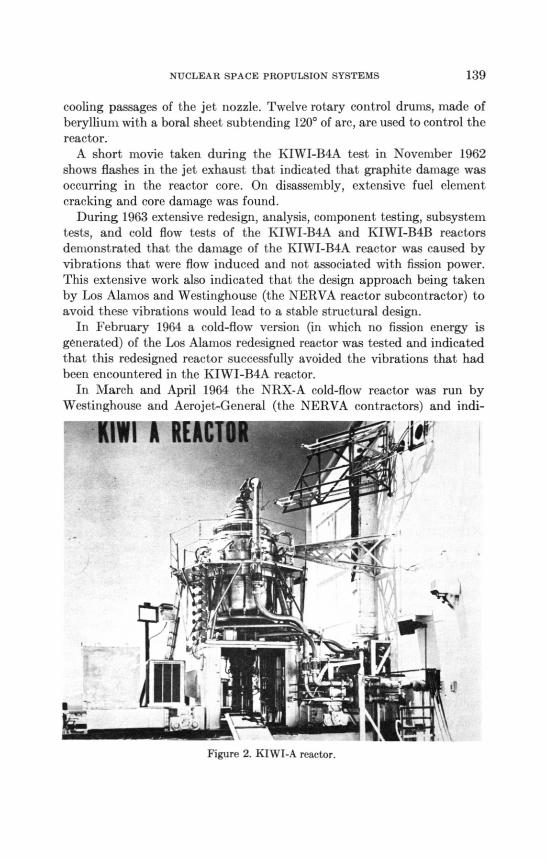
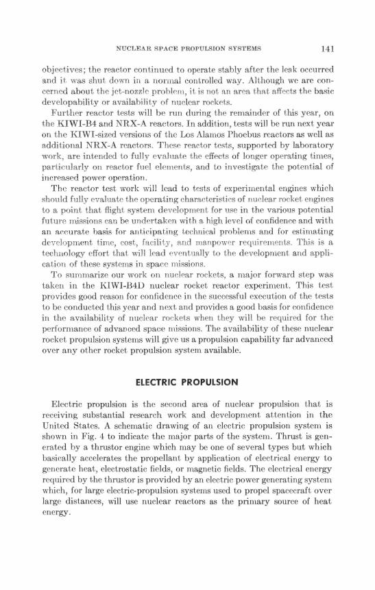
A photograph of the KIWI-A reactor is shown in Fig. 2. These tests andlater tests of the KIWI-B I reactors conducted in 1961 and 1962 providedimportant, information on 1 he design techniques, materials properties,cold-to-hot neutronic factors, verification of t,he suitability of controllingthe fission power generation of the react or by rotat ing drums ill t he reflect orportion of the react or, and demonst ration of the ability to start and operat esuch reactors using liquid hydrogen as the coolant or propellant. InNovember 1962 the KIWI-B4A reactor was tested at our Nuclear RocketDevelopment Station in Nevada. This react or (Fig. 3) was our favoreddesign for use in the NERVA (Nuclear Engine for Rocket Vehicle Appli-cation) engine, which will be our first nuclear rocket- engine.
The KIWI-NERVA reactors are grapliite-based reactors using graphit efuel elements impregnat ed with uranium carbide. The reactor core is madeup of clusters of these fuel elements and is supported by both a lateral andan axial support system. These tIpport systems must accommodate largechanges in core dimensions arising from thermal expansion of the core asthey provide for the static and dynamic loads imposed on t he core. In orderto achieve as close to uniform temperature distribution throughout thecore as possible, the uranium loading and flow distribution are adjustedradially across the core. The outer reflector cylinder in both reactors ismade of beryllium and is cooled by liquid hydrogen from the regenerative
NUCLEAR SPACE PROPULSION SYSTEMS 139
cooling passages of the jet nozzle. Twelve rotary control drums, made ofberyllium with a boral sheet subtending 1200 of arc, are used to control thereactor.
A short movie taken during the KIWI-B4A test in November 1962shows flashes in the jet exhaust that indicated that graphite damage wasoccurring in the reactor core. On disassembly, extensive fuel elementcracking and core damage was found.
During 1963 extensive redesign, analysis, component testing, subsystemtests, and cold flow tests of the KIWI-B4A and KIWI-B4B reactorsdemonstrated that the damage of the KIWI-B4A reactor was caused byvibrations that were flow induced and not associated with fission power.This extensive work also indicated that the design approach being takenby Los Alamos and Westinghouse (the NERVA reactor subcontractor) toavoid these vibrations would lead to a stable structural design.
In February 1964 a cold-flow version (in which no fission energy isgenerated) of the Los Alamos redesigned reactor was tested and indicatedthat this redesigned reactor successfully avoided the vibrations that hadbeen encountered in the KIWI-B4A reactor.
In March and April 1964 the NRX-A cold-flow reactor was run byWestinghouse and Aerojet-General (the NERVA contractors) and indi-
-11W1 A REAC,
1N11
‘7`. grViV
Figure 2. KIWI-A reactor.

140 FOURTH CONGRESS — AERONAUTICAL SCIENCES
Figure 3. KIWI-B4A reactor
cat ed that this Westinghouse design successfully avoided the vibrations
1 hat occurred in t he IXIWI-B4A reactor.Then on May 13, 1964, a major tidiest one was achieved when the
KIWI-B4D reactor was tested by the Los Alamos Scientific Laboratory atpower and temperature conditions close to the design conditions. The testwas of sufficient duration to provide a significant proof test of the structure
of the reactor, as well as !natty other reactor features. Examination ofreactor parts and data analysis have indicated successful operation of thereactor. The struct ure behaved as it was designed. No fuel elements werecracked; the vibrations encountered in the Noveniber 1962 t.ests were
successfully avoided. We can safely say that our structural problems havebeen overcome.
A short movie taken (1uring the power operation of the NIWI-B41)reactor shows how clean t he exhaust jet is compared to the earlier KIWI-
B4A test run. This indicates the successful operation of the core and thelack of core damage. The test lime was shorter than planned because of ahydrogen leak that occurred in t he jet nozzle causing a fire around the
reactor. Fortunately, this nozzle failure did not compromise our test
NUCLEA R SPACE PROPULSION SYSTEMS 141
objectives; the reactor continued to operate stably after the leak occurredand it was shut down in a normal controlled way. Although we are con-cerned about the jet-nozzle problem, it is not an area that affects the basicdevelopability or availability of nuclear rockets.
Further reactor tests will be run during the remainder of this year, onthe KIWI-B4 and NRX-A reactors. In addition, tests will be run next yearon the KIW1-sized versions of the Los Alamos Phoebus reactors as well asadditional NRX-A reactors. These reactor tests, supported by laboratorywork, are intended to fully evaluate the effects of longer operating times,particularly on reactor fuel elements, and to investigate the potential ofincreased power operation.
The reactor test work will lead to tests of experimental engines whichshould fully evaluate the operating characteristics of nuclear rocket enginesto a point that flight system development for use in the various potentialfuture missions can be undertaken with a high level of confidence and withan accurate basis for anticipating technical problems and for estimatingdevelopment time, cost, facility, and manpower requirements. This is atechnology effort that will lead eventually to the development and appli-cation of these systems in space missions.
To summarize our work on nuclear rockets, a major forward step wastaken in the KIWI-BM.) nuclear rocket reactor experiment. This testprovides good reason for confidence in the successful execution of the teststo be conducted this year and next and provides a good basis for confidencein the availability of nuclear rockets when they will be required for theperformance of advanced space missions. The availability of these nuclearrocket propulsion systems will give us a propulsion capability far advancedover any other rocket propulsion system available.
ELECTRIC PROPULSION
Electric propulsion is the second area of nuclear propulsion that isreceiving substantial research work and development attention in theUnited States. A schematic drawing of an electric propulsion system isshown in Fig. 4 to indicate the major parts of the system. Thrust is gen-erated by a thrustor engine which may be one of several types but whichbasically accelerates the propellant by application of electrical energy togenerate heat., electrostatic fields, or magnetic fields. The electrical energyrequired by the thrustor is provided by an electric power generating systemwhich, for large electric-propulsion systems used to propel spacecraft overlarge distances, will use nuclear reactors as the primary source of heatenergy.

142 FOURTH CONGRESS - AERONAUTICAL SCIENCES
REACTOR
SHIELD
BOILER
ELECTRIC GENERATORK
TURBINE
RADIATOR
PUMP
--'111,441
PUMP (10(
THRUST CHAMBER
Figure 4. Nuelear- eleetrie power and propulsion system.
While the primary applications of nuclear rockets are in the mannedmissions in space, it appears from the results of our advanced missionstudies and the theoretical performance estimates that the earliest appli-cations of nuclear electric propulsion will be in unmanned scientific andsatellite applications missions involving high velocity increments. Amongthese unmanned missions, electrie propulsion will probably be applied firstas small, attitude-control, and orbital-position-keeping engines, wherepower already available in the satellite would provide the electrical energyneeded for the electric propulsion thrustor. The electric accelerators orthrust ors for such applications could be provided in a relatively short time.Beyond these earliest electric-thrust applications we can anticipate pro-pulsion for unmanned spacecraft deep into space. Among the unmannedscientific missions for which electric propulsion may be required are thesolar probes that would be aimed at delivering spacecraft, weighing at leasta few hundred pounds, close to the sun or probes to high angles out of theplane of the planetary orbits. Ideal velocity increments for these missionswill reach 75,000 ft/sec. They, therefore, provide a potential applicationfor electric propulsion.
Beyond the unmanned spacecraft propulsion, we can anticipate mannedplanetary exploration based on nuclear electric propulsion, or moreprobably, combinations of electric propulsion and nuclear rocket propul-sion. The possible use of electric propulsion in the second stage of anearth- orbit departure vehicle (with a nuclear rocket first stage) is based ont he performance potential of high power (approximately 5 mw) nuclearelectric systems but is not yet based on real data that demonstrate the

NUCLEAR SPACE PROPULSION SYSTEMS 143
feasibility of obtaining low system weights (10-20 lb per electrical kw)with operating times of 10,000 to 20,000 hr reliably. It is of interest topoint out that if electric propulsion is to be used as the sole propulsionsystem from earth orbit to the planets in manned missions, electrical powerlevels of tens of megawatts would be required.
It is essential that data from our technology development programs beobtained to assess the performance that will eventually be achievable inthese various high-power electric propulsion systems. Because the tech-nology of such systems is not yet available and because much researchinformation remains to be accumulated, electric propulsion is at a muchearlier stage of development than is the case with the nuclear rockets thatwere described earlier.
Our work on electric propulsion is divided into two main parts since thesystem itself can be divided into two principal portions—the system thatgenerates electric power and the thrust system that uses that electric powerto accelerate the propellant, producing thrust.
ELECTRIC THRUSTOR TECHNOLOGY
There are three main types of electric thrustors, pictured schematicallyin Fig. 5: the electrothermal jet (shown as an arc jet here), the ion jet(electrostatic), and the plasma jet (electromagnetic or 1\ IHD). They differprincipally in the method used to accelerate the propellant. For example,the propellant in an electrothermal jet is accelerated by heating it in an
ARC JET
ION ENGINE
PLASMA JETLœ—""Nm..m.
R 62-351
Figure 5. Electric thrust chamber program.

144 FOURTH CONGRESS — A ERONAUTICAL SCIENCES
arc discharge or in an elect ric resistance heater and expanding it througha jet- nozzle. The ion and plasma jet s develop thrust by means of reactionsbetween the propellant in an ionized state and electrostatic and electro-magnetic fields respectively.
Our major enmhasis has been and still is on the electrostatic ion enginealthough work is also proceeding on the electromagnetic and electrothermalengines. A very significant milestone in this part of our program wasachieved on July 20, 1964, when t he SERT I (Space Electric Rocket Test)spacecraft was flown on a Scout vehicle from Wallops Island, Virginia(Fig. 6). The SERT spacecraft carried two ion engines; one having a thrustof 0.001 lb and the other a thrust of 0.006 lb. The objective of this SERTflight test was to answer conclusively the questions concerning neutraliza-tion of the exit ion beam required to avoid a buildup of space charge in theelectrostatic ion engine system, which would deteriorate the thrustcapability of the system. Ground-test data had indicated that ion beamneutralization could be accomplished by injecting electrons in the exhaustjet; however, the infinite expanse of space cannot be duplicated in any ofthe contained ground vacuum chambers. In this test the thrust of the systemWaS indicated by the spin rate of the vehicle since, as shown in Fig. 7, thethrust was directed in a tangential direction. Only the 0.006-lb thrust engineoperated during the test but its operation was so successful that neutral-
Q
BASE PLATE1
EXTENSION ARM
LI•
Or- I I1.If
4ENGINE
•
ENGINE
Figure 6. SERT-I spacecraft.

NUCLEAR SPACE PROPULSION SYSTEMS 145
Figure 7. SERT spacecraft.
ization was clearly demonstrated and the ability to start, shut down, andrestart these engines in space was also demonstrated.
The extensive data that we have obtained in ground-test facilities andin the SERT flight indicate that the technology of low-power ion enginesis available. The technology of the high-powered (megawatt) engines forthe propulsion of large manned and unmanned spacecraft is not yetavailable. It appears now that the most practical way of achieving increasedthrust with electricthrustor systems is by clustering a number of smallerthrustors. Accordingly, we have been testing a 9 module cluster of 3-kwion engines shown in Fig. 8; also a single 30-kw engine shown in Fig. 9 asthe next step toward achieving our ultimate goal of megawatt sizethrustors.This work aimed at increasing the thrust while maintaining high efficiencyand long life is a major portion of our electric propulsion program.
NUCLEAR REACTOR ELECTRIC POWER
Although much more work must be done to assure the availability ofthrustors having efficiency, life, thrust, and frontal area that will berequired in space missions, the most difficult and pacing element of electricpropulsion is the development of high-power, long-life, low-specific-weight,nuclear-reactor electric generating systems. The two systems that are beinginvestigated for electric power generation rely on the Rankine cycle, alkali

146 FOURTH CONGRESS — AERONAUTICAL SCIENCES
CH CENTERMERCURY
ARRAY
Figure 8. 30-kw nwreury electron-bombardment thrustor array.
IS RESEARCH CENTER30 KW MERCURY
RON-BOMBARDMENTTHRUSTOR
Figure 9. 30- kw mercury electron - bombardment thrustor.

NUCLEAR SPACE PROPULSION SYSTEMS 147
metal working fluid, turboalternator concept shown in Fig. 10 and thethermionic direct conversion concept shown in Fig. 11. In the turbo-generator system, heat from the nuclear reactor is converted to electricalenergy in a liquid-metal working fluid cycle operating at temperatures inthe neighborhood of 2000°F in order to achieve the extremely low weightcapability required for electric propulsion. In the thermionic direct con-version system being investigated, nuclear fission energy is used to heat acathode which emits electrons at its surface. The electrons flow across asmall gap to a cool anode and then deliver power to the external load.Both of these systems are complex; they are beyond our current techno-logical capability even though we are generally more familiar with, andmany feel more at home with the general class of components in theRankine cycle, such as turbines, pumps, etc.
As part of our work we are well along on finding the basic properties ofthe working fluids that will be used. Such information was not availablewhen we started this work in the late 1950s.In addition, long-time materialtests are underway and physical property data on refractory materials thatare suitable for use in these systems are being obtained; corrosion testloops are now beginning to provide data; a large fund of boiling andcondensing heat-transfer data is being accumulated; turbine-test facilitieshave been built and turbine tests are being initiated with potassium vapor;ground tests of low-speed meteoroid impact conditions with candidate,lightweight radiator materials have been run (although with somewhat
REACTOR 2100°FBOILER
1950°FPUMP
TURBINE1400°F
CONDENSER
rGENERATOR
PUM(.10.1.
SEGMENTED RADIATOR
Figure 10. Advanced system—turboelectric.

1-18 HiCIC111 Cl/NGRE`-;S AEIMNAUTICAL SCIENCES
ADVANCED SYSTEMTHERMIONIC DIRECT CONVERSION
FUEL ELEMENT3000 F ANODE
RADIATOR
NUCLEAR PUMP
REACTOR
OUTPUT
in ---t hennionic (Iirect conversion.
discouraging results); the space niet eoroid pullet ure models are now bet terdefined than was the case when We start ed the program. With regard to thethennionie emit ter syst ems, much infonnation ott inat erial properties isbeing accumulated, but many materials problems remain and new Oneshave been identified. Long-time e n titI er tests have been mn, including avery hunted bit of test, operation up to 8,500 hr outside of a reactor. Theproblems of operating tliese emit iers are better understood and designsaimed at avoiding t he major ones are being defined.
Some examples of our work in t his area and the results we have obtainedare indicated in t he next several slides. Figure 12 indicates the propertydata that, have been obtained for potassium and sodium liquid and vaporas a result of our work in comparison with the information t hat was avail-able before our program started. You will note that there are significantareas in winch t here were no previous expefimental data. You will alsonotice that t he range of temperat tires over which data are now available issubstantially greater than that which was available earlier. Such infor-mation on the basic properties of t he materials is obviously essential in thedesign of any power system utilizing t hese working fluids. Figure 13 indi-cates some of the single-t ube boihng heat-transfer data that have beenobtained with potassium over a wide range of quality, presented as percent,of vapor. With helical inserts, extremely high heat-transfer coefficients areobtained even into the high-quality region. Figure 14 shows the turbine-

NUCLEAR SPACE PROPULSION SYSTEMS149PREVIOUSTHIS WORKDATA FROM
STATEMETALDATA(°F)
VAPORPOTASSIUM1100-1850900-2100
SODIUM1500-2000900-2100
LIQUIDPOTASSIUM150-1300300-2100
SODIUM200-1500300-2500
VAPORPOTASSIUMNONE900-2100
SODIUMNONE900-2500
VAPORPOTASSIUMNONE900-2100
SODIUMNONE900-2500
LIQUIDPOTASSIUM150-150032-2100
SODIUM200-1650300-2100
VAPORPOTASSIUMNONE300-2100
SODIUMNONE300-2100
LIQUIDPOTASSIUM150-1300150-2100
LIQUIDPOTASSIUM800-1140200-1500
VAPORPOTASSIUMNONE900-2100
LIQUIDPOTASSIUM150-900200-2100
Figure 12.Property measurements.
PROPERTY
VAPOR PRESSURE
DENSITY
PRESSUREVOLUME
EMPERATURE T
SPECIFIC HEAT
VISCOSITY
THERMAL CONDUCTIVITY
SURFACE TENSION
MEAT P, JR 2E0,00000 EIT RRIRT2
SOEITIM HEATING TEMPERATURE INSO°E
POTASSIUM Boo ING TF MRERATNRE 16000700-f
F E T J A, AROR
NASA RN64-I573
Figure 13. Potassium single-tube boiler test data.
INSERT
0
0
oHELICA.
0 0
0 00 0
0 0o0
0 0OD
NO INSER-
O
o
Ot; 34
HEAT
TRANSER
20
0

150 Fotncr coNOnEss — 1EIWNAUTICAL SCIENCES
test installation at ticiaTal Elect He that is now being used for t urbine testsunder cont met wit h NASA. Information on the effects of moisture on botht he erosion charact erist ics and performance characteristics of the potassiumturbine will be obtained ill his test installation. Additional turbine re-search work is underway at t he NASA Lewis Research Center.
Because of the large weight associated with radiators in high-powernuclear electric power supplies and the importance of reducing overallsystem weight to assure t hat t he performance potential of electric pro-pulsion may be achieved, considerable effort is being devoted to evaluationof tlw design and resulting weight of radiators. One of the major uncer-tainties is and has been t he prof ect ion required on radiator tubes to assurethat they will not be penetrat ed by meteoroids during a space-flightmission. Evaluation of t he met eoroid environment in space and develop-ment of models 1 o predict the pellet rat ion resulting from meteoroids have,therefore, been invest igat ed. As indicated earlier, the meteoroids penetra-tion model correlations have been substantially improved during the pastyear. However, the select ion of a lightweight material for use in fabricatingthe radial or is still under investigation. Figure 15 shows the relativeradiator weights for I he various mat erials 1-hat have been considered. Youwill note that beryllium is by far the lightest material for such application.
POTASSIUM TURBINE INSTALLED ON TEST STAND
Figure 14. Potassium test turbine installation.

NUCLEAR SPACE PROPULSION SYSTEMS 151
However, as shown in Fig. 16, beryllium tends to crack when it is impactedby projectiles simulating meteoroid projectiles. It should be noted that inthis case a %-in.-diameter glass projectile with a velocity of 25,000 ft/secimpacted the beryllium tube sample. These velocities are substantiallylower than the meteoroid velocities that would be encountered in space.Because of this cracking problem, the use of beryllium is at this point
POTASSKIM FLUID, PEAK CYCLE TEMPERATURE 2000° F
RELATIVE RADIATOR
WEIGHT
WT MATERIAL M
10
9
a......,
7
6
5
4
3
2
0900
',....."-...
..-
COLUMBIUM
1000HOE)
, TITANIUM
i ",- TANTALUM
..., ...,'
z-VANAGIUM
STAINLESS S'6.
GRAPHITE
_
MOLYBDENUM
PYROLYTIC GRAPHITE
BERYLLIUM
1200130014001500RADIATOR TEMP, °F
1600 1700
MINIMUM WT-
BERYLLIUM
Figure 15. Radiator relative weight.
FRONT SIDE
'4 WD.
0INCHI
1300° F ROOM 13000 F ROOM
TEMP TEMP
1/8 IN DIAM GLASS PROJECTILE — 25,000 FT/SEC (NOMINAL)
Figure 16. Impact into beryllium tubes.

152 FOURTH CONGRESS - AERONAUTICAL SCIENCES
uncertain and it, is conceivable I hat more ductile materials may be requiredin our radiator struct ures. Should this be the case, the weight of nuclearelectric power supplies may increase substantially above the values thatwould be desired to achieve the full performance potential of electricpropulsion.
Interesting information has also been obtained wit h regard to thermionicdirect conversion systems. As shown in Fig. 17, it has been found that incertain concepts in which the emitter or the hot cathode portion of thethermionic emitter encopsulates the nuclear fuel material, an open circuitwill lead to a substantial increase in the temperature of that emitter system.To achieve maximum power output of these systems, it is desirable tooperate them at the highest possible temperature. Designs are now underconsideration that would attempt to avoid this large margin for open-circuit emitter temperature that would have to be provided.
As I indigated earlier, considerable progress has been made with respectto converter life. Figure 18 lists some of the results of single cell electricallyheated converter tests in the United States. To orient you as to our goals,useful performance consistent with the units shown on the slide would beabout 10 watts/cm' ideal power with efficiency of about 20 percent. It canbe seen that impressive performance and operating times are beingachieved. It is a far cry, however, from these simple laboratory tests to anoperational thermionic reactor.
In addition to this work on the nonreactor portions of electric propulsion,it is important to emphasize that the US Atomic Energy Commission,
4600
OPEN
CIRCUIT
TEMP.-F4400
4000
36002800 3200 3600
OPERATINGTEMP.-FFigure 17. Open-circuit emitter temperature vs. operating emitter temperature.

NUCLEAR SPACE PROPULSION SYSTEMS 153
ConverterDesignation
Emitter Temperature°C
CollectoroC
Gapmils.
IdealPower
Density,Watts/cm`
Efficiency I.
TimeHrs Remarks
301 1810 703 10 9. 2 12. 9 2215 Continuing on test
303 1790 610 10 9. 5 12.4 916 Failed due toemitter leak
402 1725 650 10 6. 2
3650 Continuing
403 1730 703 10 7. 2
1812 Continuing
405 1780 70010 5
1175 Continuing
(Ni Collector)
406 1825 710 5 13.0
1915 Continuing
LC-1 1800 700 10 & 5 12.0 1250 Continuing
LC-2 17(X) 700 10 & 5 I4. 0 200 Continuing
0C-4 1750 650
(CO 11 5.0 9. 2 1351 Stopped forexamination
0C-5 1800 700 10 I L 0 16. 0 260 Cell broken duringinstrument replace-ment
Figure 18. Out-of-pile converter tests.
working closely with NASA and the US Air Force, is establishing the basictechnology for the reactors that will be required in generating electricpower for electric propulsion. The AEC is investigating various fuel forms,their burnout characteristics, the power output and power distribution thatresults from various reactor configurations, and, in general, all otherresearch and technology factors leading to the actual development ofreactors for such systems.
ADVANCED CONCEPTS
In addition to the solid-fuel-element nuclear rockets and electric pro-pulsion, I have indicated earlier that there are several advanced nuclearconcepts that are not yet well defined but are receiving research attentionto evaluate their feasibility and real performance potential. The gas corereactor nuclear rocket is one of these systems. One of the several gas corereactor concepts that is being studied is shown in Fig. 19. The objective inthis kind of a nuclear rocket is to avoid the temperature limit that resultsfrom the use of solid-fuel-element materials. In this concept the uraniumfuel is held in a highly concentrated core in a gaseous form. Various forcefields haVe been suggested to accomplish this uranium concentration. Inthe case shown, the uranium is held in place by centrifugal force. Hydrogenwould be heated to extremely high temperatures so that specific impulsesabove 1,500 sec may eventually be achievable.

154 FOURTH CoNGUEss - AERoNAUTICAL SCIENCES
PROPELLANT TANK
PUMP
TURBINE
PRESSURE SNELL
MODERATOR-REFLECTOR
NOZZLE
GENERAL LOCATION
OF GASEOUS NUCLEAR FUEL
Figure 19. laseous-core nuclear rocket.
Another advanced propulsion concept receiving sonic attention is theOrion concept illust rated schematically in Fig. 20. In this concept a rapidsuccession of nuclear explosions below the pusher plat e imparts an upwardforce through a shock-absorber system to a large space vehicle. Analyticalwork and some high-energy explosive testing have been conducted on thisconcept. No nuclear tests have been undertaken.
There are, in addition, several other concepts that are being studied,but I must emphasize that alt hough the performance that has beentheoretically calculated for these various syst CMS offers some advantage,the attainability of this performance potential and the feasibility ofdeveloping these systems are not yet established.
SUMMARY
Space propulsion using nuclear energy sources offers a capability foraccomplishment of high-energy increntent, high-payload missions in spacebeyond the capabilit y of the chemical combustion propulsion systems whenconsidering practical operating limitations. Work now underway in theUnited St at es indicat es 1hat nuclear rockets can be anticipated for earliestuse in the space program. React or tests being conducted during this yearshould provide a firm technical basis for system development. Electricpropulsion using the nuclear react or energy source offers promising storable-propellant performance if lightweight, long-life power supplies can bedeveloped. Technology investigations are now underway to evaluate the

NUCLEAR SPACE PROPULSION SYSTEMS 155
SHOCK
ABSORBER
SYSTEM
PUSHERPLATE
).40/..... PULSE UNIT
Figure 20. Orion pulse propulsion system.
feasibility of achieving the required performance. This work will simul-taneously provide the information that is required to provide large amountsof electric power for nonpropulsive purposes in space. Beyond thesesystems, a host of new and advanced concepts have been proposed. Theseare not well enough defined or evaluated to assure that their high perform-ance potential can actually be achieved. Some research work is underwayon these systems.
VEHICLE