Nuclear Magnetic Resonance Logging While Drilling...
5
Nuclear Magnetic Resonance Logging While Drilling (NMR-LWD): From an Experiment to a Day-to-Day Service for the Oil Industry Martin Blanz, Thomas Kruspe, Holger Frank Thern, Gerhard Alfons Kurz Baker Hughes Incorporated Corresponding author: Martin Blanz, Baker Hughes, Celle Technology Center, Baker-Hughes-Str. 1, 29221 Celle, Germany, E-Mail: [email protected] Abstract NMR T 2 distribution measurement is our chosen everyday method for NMR logging while drilling oil and gas wells. This method yields straightforward preparation and execution of the job as well as a normally easy interpretation of the measured data. For instance, gas and light oil discrimination against water is feasible by direct observation of the T 2 distribution. A condition for this measurement method is a NMR logging tool that hardly moves while drilling and in addition uses a small static magnetic field gradient and short inter-echo time TE to be motion tolerant. Using data compression techniques, we can transmit by mud pulse telemetry the T 2 distribution in real time from the borehole to the surface. This enables the drilling operator to use the NMR data for real-time decisions such as geosteering. Keywords NMR, well logging, while drilling, T 2 , low field gradient 1. Introduction to downhole NMR In oil and gas well logging, nuclear magnetic resonance (NMR) has long been considered to be a non-routine service because of its complex physics, difficult job preparation, and the highly trained people required for data processing and interpretation. It was only used when other measurements failed to give the complete answer. With recent developments in the field of NMR logging while drilling (LWD), more standard applications became feasible. The development of slimhole NMR LWD technology [1] expands the range of applicable hole sizes from 10⅝ in. down to 5¾ in.-diameter holes. Wireline technology (lowering measuring instruments by a cable into a borehole after drilling) was developed toward high-end applications comprising many options offered by NMR physics. These applications include diffusion characterization and two-dimensional analysis, as well as multiple frequency and multiple wait-time measurements. In contrast to this tendency, the LWD technology that we developed is for everyday applications, vastly The Open-Access Journal for the Basic Principles of Diffusion Theory, Experiment and Application (received 13 September 2010, accepted 19 November 2010) © 2010, M. Blanz diffusion-fundamentals.org 14 (2010) 2, pp 1-5 1
Transcript of Nuclear Magnetic Resonance Logging While Drilling...

Nuclear Magnetic Resonance Logging While Drilling (NMR-LWD):
From an Experiment to a Day-to-Day Service for the Oil Industry
Martin Blanz, Thomas Kruspe, Holger Frank Thern, Gerhard Alfons Kurz
Baker Hughes Incorporated
Corresponding author: Martin Blanz, Baker Hughes, Celle Technology Center,
Baker-Hughes-Str. 1, 29221 Celle, Germany, E-Mail: [email protected]
Abstract
NMR T2 distribution measurement is our chosen everyday method for NMR logging while
drilling oil and gas wells. This method yields straightforward preparation and execution of the
job as well as a normally easy interpretation of the measured data. For instance, gas and light
oil discrimination against water is feasible by direct observation of the T2 distribution. A
condition for this measurement method is a NMR logging tool that hardly moves while
drilling and in addition uses a small static magnetic field gradient and short inter-echo time
TE to be motion tolerant. Using data compression techniques, we can transmit by mud pulse
telemetry the T2 distribution in real time from the borehole to the surface. This enables the
drilling operator to use the NMR data for real-time decisions such as geosteering.
Keywords
NMR, well logging, while drilling, T2, low field gradient
1. Introduction to downhole NMR
In oil and gas well logging, nuclear magnetic resonance (NMR) has long been considered
to be a non-routine service because of its complex physics, difficult job preparation, and the
highly trained people required for data processing and interpretation. It was only used when
other measurements failed to give the complete answer. With recent developments in the field
of NMR logging while drilling (LWD), more standard applications became feasible. The
development of slimhole NMR LWD technology [1] expands the range of applicable hole
sizes from 10⅝ in. down to 5¾ in.-diameter holes.
Wireline technology (lowering measuring instruments by a cable into a borehole after
drilling) was developed toward high-end applications comprising many options offered by
NMR physics. These applications include diffusion characterization and two-dimensional
analysis, as well as multiple frequency and multiple wait-time measurements. In contrast to
this tendency, the LWD technology that we developed is for everyday applications, vastly
The Open-Access Journal for the Basic Principles of Diffusion Theory, Experiment and Application
(received 13 September 2010, accepted 19 November 2010)
© 2010, M. Blanzdiffusion-fundamentals.org 14 (2010) 2, pp 1-5 1
simplifying the complicated measurement and processing concepts developed by wireline
counterparts.
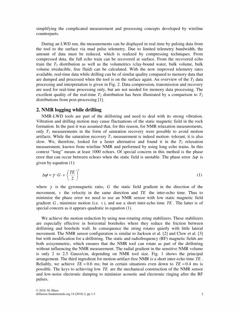
During an LWD run, the measurements can be displayed in real time by pulsing data from
the tool to the surface via mud pulse telemetry. Due to limited telemetry bandwidth, the
amount of data must be reduced, which is realized by compressing techniques. From
compressed data, the full echo train can be recovered at surface. From the recovered echo
train the T2 distribution as well as the volumetrics (clay-bound water, bulk volume, bulk
volume irreducible, free fluid) can be calculated. With the now improved telemetry rates
available, real-time data while drilling can be of similar quality compared to memory data that
are dumped and processed when the tool is on the surface again. An overview of the T2 data
processing and interpretation is given in Fig. 2. Data compression, transmission and recovery
are used for real-time processing only, but are not needed for memory data processing. The
excellent quality of the real-time T2 distribution has been illustrated by a comparison to T2
distributions from post-processing [1].
2. NMR logging while drilling
NMR-LWD tools are part of the drillstring and need to deal with its strong vibration.
Vibration and drilling motion may cause fluctuations of the static magnetic field in the rock
formation. In the past it was assumed that, for this reason, for NMR relaxation measurements,
only T1 measurements in the form of saturation recovery were possible to avoid motion
artifacts. While the saturation recovery T1 measurement is indeed motion- tolerant, it is also
slow. We, therefore, looked for a faster alternative and found it in the T2 relaxation
measurement, known from wireline NMR and performed by using long echo trains. In this
context “long” means at least 1000 echoes. Of special concern in this method is the phase
error that can occur between echoes when the static field is unstable. The phase error ϕ∆ is
given by equation (1):
2
2
⋅⋅⋅=∆
TEvGγϕ (1)
where γ is the gyromagnetic ratio, G the static field gradient in the direction of the
movement, v the velocity in the same direction and TE the inter-echo time. Thus to
minimize the phase error we need to use an NMR sensor with low static magnetic field
gradient G , minimize motion (i.e. v ), and use a short inter-echo time TE . The latter is of
special concern as it appears quadratic in equation (1).
We achieve the motion reduction by using non-rotating string stabilizers. These stabilizers
are especially effective in horizontal boreholes where they reduce the friction between
drillstring and borehole wall. In consequence the string rotates quietly with little lateral
movement. The NMR sensor configuration is similar to Jackson et al. [2] and Clow et al. [3]
but with modification for a drillstring. The static and radiofrequency (RF) magnetic fields are
both axisymmetric, which ensures that the NMR tool can rotate as part of the drillstring
without influencing the NMR measurement. The radial gradient in the sensitive NMR volume
is only 2 to 2.5 Gauss/cm, depending on NMR tool size. Fig. 1 shows the principal
arrangement. The third ingredient for motion-artifact-free NMR is a short inter-echo time TE .
Reliably, we achieve =TE 0.6 ms; but in certain situations even down to =TE 0.4 ms is
possible. The keys to achieving low TE are the mechanical construction of the NMR sensor
and low-noise electronic damping to minimize acoustic and electronic ringing after the RF
pulses.
© 2010, M. Blanzdiffusion-fundamentals.org 14 (2010) 2, pp 1-5 2

Fig. 1: Illustration of the NMR sensor as part of the drillstring.
The ability to log high quality T2 data while drilling is validated by an excellent match of
while-drilling and relog T2 data as shown in [4]. Furthermore, comparison of LWD data to
wireline data emphasizes the quality of the T2 data acquired while drilling [5].
3. Advantages of a small static field gradient
In the previous section, we explained why a small static field gradient enables the
acquisition of motion-artifact-free long echo trains. But a small gradient presents a further
advantage. The T2 relaxation (equation (2)) is governed by bulk liquid relaxation, surface
relaxation and diffusion:
DTEGV
S
TT bulk
2
,22
)(12
111γρ ++= (2)
where T2,bulk is the bulk T2 relaxation time of the fluid in the pore, ρ is the surface relaxivity, S
and V are surface and volume of the pores and D is the diffusivity of the fluid in the pore.
A small field gradient G and short inter-echo time TE render the diffusion term
insignificant, i.e. we are able to measure intrinsic T2. This simplifies the interpretation of the
measured T2 distribution (for an explanation of T2 distribution and partial porosities see Fig.
2). Without diffusion effect, T2 is long in light (low-viscous) oil and gas, allowing us to
discriminate these hydrocarbon (HC) fractions from heavier (higher viscosity) oil and water.
Our experience shows that light HC quantification is indeed accomplished by a simple T2
cutoff approach for many applications. Mixed- or oil-wet conditions, only if they substantially
shorten the HC T2, pose a limitation to this approach. However, we hardly encountered these
conditions in practice so far. Furthermore, a substantial amount of while-drilling runs takes
place in horizontal or highly inclined wells where the reservoir is known to contain no
movable water. Thus, it is particularly easy to identify the HC volume as the movable fluid
volume. This even applies, if mud filtrate invades into the formation, replacing part of the
native HC. Invasion, though, is affecting LWD data less than wireline data.
Low-gradient static magnetic field (2 to 2.5 G/cm)
Sensitive region about 1 liter
Radio frequency field
Permanent magnets
Transmitter and receiver coils
Transmission of T2 data in real time via mud pulse telemetry
Rotating drillstring
intrinsic T2 relaxation due to
diffusion
© 2010, M. Blanzdiffusion-fundamentals.org 14 (2010) 2, pp 1-5 3

Inter-Echo Time, TE Time
Am
plit
ude
NMR EchoesRF Pulses
Wait Time, TW TimeT2 relaxation
Polarization by T1 relaxation
Am
plit
ud
e
Inter-Echo Time, TE Time
Am
plit
ude
NMR EchoesRF Pulses
Wait Time, TW TimeT2 relaxation
Polarization by T1 relaxation
Am
plit
ud
e
Fig. 2: The ORPS measurement and the processing
steps leading to the real-time partial porosities.
ORPS is an echo sequence similar to CPMG but
with tipping angles (RF pulse lengths) optimized
for inhomogeneous static and RF fields [6].
An example is shown in a while-drilling
log from the North Sea, characterizing a
chalk reservoir along a horizontal well path
(Fig. 3) [7]. Track 1 shows natural gamma
ray (GR), borehole size (caliper), and
drilling speed (rate of penetration). Track 2
shows the NMR T2 distribution incl.
separation into bound water (BW) and free
(i.e. producible) fluids by a T2 threshold
(BW cutoff). Track 3 shows the NMR
porosity, incl. separation into free fluid and
bound water, compared to neutron porosity
and formation density.
X
X
X
X
X
X
X
X
X
X
X
X
X
X
X
LightOil
X
X
X
X
X
X
X
X
X
X
X
X
X
X
X
X
X
X
X
X
X
X
X
X
X
X
X
X
X
X
X
X
X
X
X
X
X
X
X
X
X
X
X
X
X
LightOil
Fig. 3: Log of various LWD measurements in a
North Sea Chalk, characterizing the reservoir. For
details see text.
Rock Matrix Dry
Clay
Clay Bound Water
Free Fluid Bulk
Volume Irreducible
Heavy
Oil Medium
Oil Light
Oil & Gas Tar
Part
ial P
oro
sit
y
T2 (ms)
Partial porosities & fluid response
Optimised Rephasing Pulse Sequence (ORPS)
Downhole NMR data compression
Data transmission to surface by mud pulse telemetry
Data recovery at surface
T2 inversion (Laplace transform)
Realtime T2 distribution
NMR echo sequence
© 2010, M. Blanzdiffusion-fundamentals.org 14 (2010) 2, pp 1-5 4

Low GR indicates the HC-bearing chalk reservoir sections. High GR indicates tight chalk
and shale beds. This corresponds to the T2 distribution signature and the NMR volumetrics,
which show free fluid (i.e. medium to long T2 components) in the chalk reservoir section but
none in the tight chalk and shale beds. NMR provides the unique opportunity to characterize
the reservoir quality by separating bound water and producible fluid. This information can
also be used to estimate an (uncalibrated) permeability index not shown in the figure.
The light oil, present in the formation, is apparent in the T2 distribution as a late T2 peak.
This finding is confirmed by the neutron porosity and density data. The porosity from the
neutron measurement is proportional to the density of hydrogen atoms (hydrogen index, HI)
like the porosity from the NMR measurement. Therefore, both will underestimate porosity for
light oil and gas with HI < 1. The density measurement reflects the gas density and, therefore,
yields low values. This behavior is typically used to identify light oil and gas by a crossover
between the density on one hand vs. neutron and NMR on the other hand (i.e. neutron and
NMR porosity read low compared to equivalent density porosity) as shown in the log
example. During drilling of the well, rock cores were taken to surface and investigated in a
lab. The porosity values of the core, without fluid effects, validate the light oil and gas
crossover in the log example and confirm the porosities of the different measurements.
Combining the information from all downhole measurements yields an accurate
description of the reservoir which is used to assess the commercial viability of a reservoir by
critical information such as the amount of producible hydrocarbon, the extension of the
reservoir sections, and the expected production performance.
4. Conclusions
NMR technology plays an increasingly important role for hydrocarbon reservoir
characterization. With a proper tool design an NMR T2 measurement can be performed while
drilling, independent of drilling motion and vibration. The key elements for the design are
mechanical stabilization of the tool, a small magnetic field gradient and a short inter-echo
time TE. The small field gradient and short inter-echo time suppress the diffusion effect and,
therefore, enable an easy detection and quantification of light oil and gas components in a
reservoir.
References
[1] T. Kruspe, H.F. Thern, G. Kurz, M. Blanz, R. Akkurt, S. Ruwaili, D. Seifert, A.F. Al
Marsala, Slimhole Application of Magnetic Resonance while Drilling, SPWLA 50th
Annual Logging Symposium, The Woodlands, Texas, United States, (2009).
[2] Jackson et al., US patent 4,350,955.
[3] Clow et al., US patent 4,629,986.
[4] Marzorati D., Barbieri E., Thern H. F., Scanavino D., Tilsley-Baker R., Benefield M.,
Kruspe T., Fischer M., Magnetic Resonance While Drilling for Geosteering and Rock
Quality Differentiation, presented at OMC, Ravenna, Italy, March 28-30, 2007.
[5] Akkurt, R., Marsala, A.F., Seifert, D., Al-Harbi, A., Buenrostro, C., Kruspe, T., Thern,
H.F., Kurz, G., Blanz, M., and Kroken, A., Collaborative development of a slim LWD
NMR tool: from concept to field testing, SPE Saudi Arabia Section Technical
Symposium and Exhibition, Al Khobar, Saudi Arabia, 9-11 May, 2009.
[6] Hawkes et al., US patent 6,466,013 B1.
[7] A.K. Thorsen, T. Eiane, H.F. Thern, P. Fristad, S. Williams, Magnetic Resonance in
Chalk Horizontal Well Logged With LWD, SPE Res Eval & Eng, 13 (4): 654-666, SPE-
115699-PA.
© 2010, M. Blanzdiffusion-fundamentals.org 14 (2010) 2, pp 1-5 5