
NUCLEAR INSTRUMENTS AND METHODS I29 (I975) I47-I54 ...
8
NUCLEAR INSTRUMENTS AND METHODS I29 (I975) I47-I54; © NORTH-HOLLAND PUBLISHING CO. RADIOGRAPHIC EXAMINATION OF IRRADIATED IN-CORE NEUTRON DETECTORS HELMUTH BOCK and ANTON ZEILINGER Atominstitut, A-1020 Vienna, Schiittelstrafle 115, Austria Received 4 August 1975 For the non-destructive investigation of irradiated in-core neu- self-powered neutron detectors with Co-, Er-, Hf- and Pt-emitters tron detectors neutron-radiography has been applied. Both by and a miniature fission chamber were investigated thus revealing direct and indirect methods a good resolution for critical detec- the limits of conventional radiography compared to neutron- tor parts was achieved. With these two methods irradiated radiography when highly active objects are investigated. 1. Introduction In-core neutron detectors are exposed to the worst environment experienced by any commercial product. Besides the exposure to high temperature and pressure the detectors must also withstand intense gamma- and neutron irradiation. Therefore very high quality standards are applied to any component of these neutron flux sensors. The former USAEC has released a series of standards covering different parts of in-core neutron detectors1-5). At present there are two types of in-core detectors which are used in boiling and pressurized water reactors, the miniature fission chamber and the self- powered neutron detector. Both detector types com- bine several advantages with some disadvantages. The fission chamber produces a prompt and strong detector signal resulting from gas multiplication effects in the filling gas (argon) under the applied voltage. The gas and the chamber's voltage are also the main disadvantages, because any loss of argon and the production of leakage currents must be prevented in order to get a true detector signal. The self-powered neutron detectors show either a prompt (Co, Er, Hf, Pt) or a delayed (Rh, V) detector signal which is rather weak compared to the fission chamber. This is their main disadvantage. These detectors are however all solid detectors and therefore more rugged and cheaper in production. Figs. 1 and 2 show schematic diagrams of both detector types. Their design, operation characteristics and in-core behaviour have been described in earlier papers6-15). About the operation experience and long-term behaviour of in-core detectors only few data are published 16-1 s) and detector producing companies are reluctant to release any realistic figures about failure rates. Failures have occurred both with fission cham- bers and self-powered neutron detectors which are partially caused by systematic errors in the detector design. Failed in-core detectors are subjected to extensive investigations usually by destructive methods in order to analyze the critical detector parts. The critical detector parts with fission chambers are the electrode with the uranium coating, the metal-to- ceramic seal and the mineral insulated cane. The fission chamber electrode is usually coated with 7 / / 2 Braze Emitter 21o mm Collector 3oo mm .I Braze Fig. 1. Schematic diagram of a self-powered neutron detector. (1) Emitter - vanadium, rhodium, cobalt, platin, etc. ; (2) insulator - aluminiumoxide; (3) collector - Inconel; (4) cable - mineral insulation, two cores, sheath of Inconel; (5) adapter - Ineonel; (6) end plug - Inconel; (7) aluminiumoxide tube, thermal shield during brazing. 147
Transcript of NUCLEAR INSTRUMENTS AND METHODS I29 (I975) I47-I54 ...
N U C L E A R I N S T R U M E N T S A N D M E T H O D S I 2 9 (I975) I 4 7 - I 5 4 ; © N O R T H - H O L L A N D P U B L I S H I N G CO.
R A D I O G R A P H I C E X A M I N A T I O N OF IRRADIATED IN-CORE N E U T R O N DETECTORS
H E L M U T H B O C K and A N T O N Z E I L I N G E R
Atominstitut, A-1020 Vienna, Schiittelstrafle 115, Austria
Received 4 Augus t 1975
For the non-des t ruct ive invest igat ion o f i rradiated in-core neu- self-powered neu t ron detectors with Co-, Er-, Hf- and Pt-emit ters t ron detectors neu t ron - rad iography has been applied. Both by and a min ia ture fission chamber were investigated thus revealing direct and indirect me thods a good resolut ion for critical detec- the limits o f convent ional rad iography compared to neu t ron- tor parts was achieved. With these two me t hods irradiated rad iography when highly active objects are investigated.
1. Introduction
In-core neutron detectors are exposed to the worst environment experienced by any commercial product. Besides the exposure to high temperature and pressure the detectors must also withstand intense gamma- and neutron irradiation. Therefore very high quality standards are applied to any component of these neutron flux sensors. The former USAEC has released a series of standards covering different parts of in-core neutron detectors1-5).
At present there are two types of in-core detectors which are used in boiling and pressurized water reactors, the miniature fission chamber and the self- powered neutron detector. Both detector types com- bine several advantages with some disadvantages. The fission chamber produces a prompt and strong detector signal resulting from gas multiplication effects in the filling gas (argon) under the applied voltage. The gas and the chamber's voltage are also the main disadvantages, because any loss of argon and the production of leakage currents must be prevented in order to get a true detector signal.
The self-powered neutron detectors show either a
prompt (Co, Er, Hf, Pt) or a delayed (Rh, V) detector signal which is rather weak compared to the fission chamber. This is their main disadvantage. These detectors are however all solid detectors and therefore more rugged and cheaper in production.
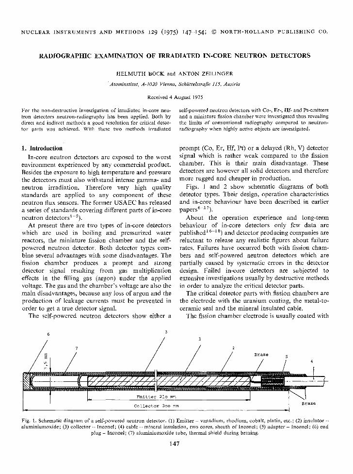
Figs. 1 and 2 show schematic diagrams of both detector types. Their design, operation characteristics and in-core behaviour have been described in earlier papers6-15).
About the operation experience and long-term behaviour of in-core detectors only few data are published 16-1 s) and detector producing companies are reluctant to release any realistic figures about failure rates. Failures have occurred both with fission cham- bers and self-powered neutron detectors which are partially caused by systematic errors in the detector design. Failed in-core detectors are subjected to extensive investigations usually by destructive methods in order to analyze the critical detector parts.
The critical detector parts with fission chambers are the electrode with the uranium coating, the metal-to- ceramic seal and the mineral insulated cane.
The fission chamber electrode is usually coated with
7 / / 2
Braze
Emitter 21o mm
Collector 3oo mm .I Braze
Fig. 1. Schematic d i ag ram of a self-powered neu t ron detector. (1) Emit ter - vanad ium, rhod ium, cobalt, platin, etc. ; (2) insula tor - a lumin iumoxide ; (3) collector - Inconel ; (4) cable - mineral insulat ion, two cores, shea th o f Inconel ; (5) adapter - Ineonel ; (6) end
p lug - Inconel ; (7) a lumin iumoxide tube, thermal shield dur ing brazing.
147
I - IELMUTH B{SCK A N D A N T O N Z E I L I N G E R 148
7 6 5 2 1 7 3 4
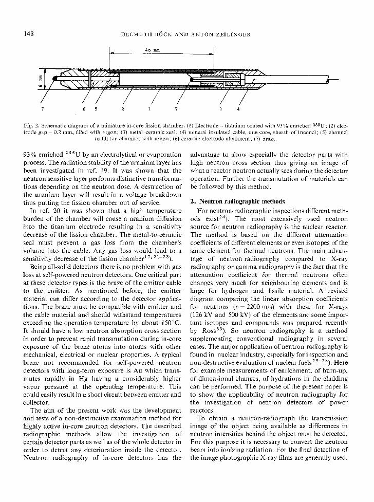
Fig. 2. Schematic diagram of a miniature in-core fission chamber. (1) Electrode - titanium coated with 93% enriched zaaU; (2) elec- trode gap - 0.2 mm, filled with argon; (3) metal-ceramic seal; (4) mineral insulated cable, one core, sheath of Inconel; (5) channel
to fill the chamber with argon; (6) ceramic electrode alignment; (7) braze.
93% enriched 235 U by an electrolytical or evaporation process. The radiation stability of the uranium layer has been investigated in ref. 19. It was shown that the neutron sensitive layer performs distinctive transforma- tions depending on the neutron dose. A destruction of the uranium layer will result in a voltage breakdown thus putting the fission chamber out of service.
In ref. 20 it was shown that a high temperature burden of the chamber will cause a uranium diffusion into the titanium electrode resulting in a sensitivity decrease of the fission chamber. The metal-to-ceramic seal must prevent a gas loss from the chamber 's volume into the cable. Any gas loss would lead to a sensitivity decrease of the fission chamber t 7, 21--23).
Being all-solid detectors there is no problem with gas loss at self-powered neutron detectors. One critical part at these detector types is the braze of the emitter cable to the emitter. As mentioned before, the emitter material can differ according to the detector applica- tions. The braze must be compatible with emitter and the cable material and should withstand temperatures exceeding the operation temperature by about 150°C. I t should have a low neutron absorption cross section in order to prevent rapid transmutation during in-core exposure of the braze atoms into atoms with other mechanical, electrical or nuclear properties. A typical braze not recommended for self-powered neutron detectors with long-term exposure is Au which trans- mutes rapidly in Hg having a considerably higher vapor pressure at the operating temperature. This could easily result in a short circuit between emitter and collector.
The aim of the present work was the development and tests of a non-destructive examination method for highly active in-core neutron detectors. The described radiographic methods allow the investigation of certain detector parts as well as of the whole detector in order to detect any deterioration inside the detector. Neutron radiography of in-core detectors has the
advantage to show especially the detector parts with high neutron cross section thus giving an image of what a reactor neutron actually sees during the detector operation. Further the transmutation of materials can be followed by this method.
2. Neutron radiographic methods For neutron-radiographic inspections different meth-
ods exist2~). The most extensively used neutron source for neutron radiography is the nuclear reactor. The method is based on the different attenuation coefficients of different elements or even isotopes of the same element for thermal neutrons. The main advan- tage of neutron radiography compared to X-ray radiography or gamma radiography is the fact that the attenuation coefficient for thermal neutrons often changes very much for neighbouring elements and is large for hydrogen and fissile material. A revised diagram comparing the linear absorption coefficients for neutrons (v = 2200 m/s) with these for X-rays (126 kV and 500 kV) of the elements and some impor- tant isotopes and compounds was prepared recently by Ross39). So neutron radiography is a method supplementing conventional radiography in several cases. The major application of neutron radiography is found in nuclear industry, especially for inspection and non-destructive evaluation of nuclear fuels 2 s-2 s). Here for example measurements of enrichment, of burn-up, of dimensional changes, of hydrations in the cladding can be performed. The purpose of the present paper is to show the applicability of neutron radiography for the investigation of neutron detectors of power reactors.
To obtain a neutron-radiograph the transmission image of the object being available as differences in neutron intensities behind the object must be detected. For this purpose it is necessary to convert the neutron beam into ionizing radiation. For the final detection of the image photographic X-ray films are generally used.
R A D I O G R A P H I C E X A M I N A T I O N OF D E T E C T O R S 149
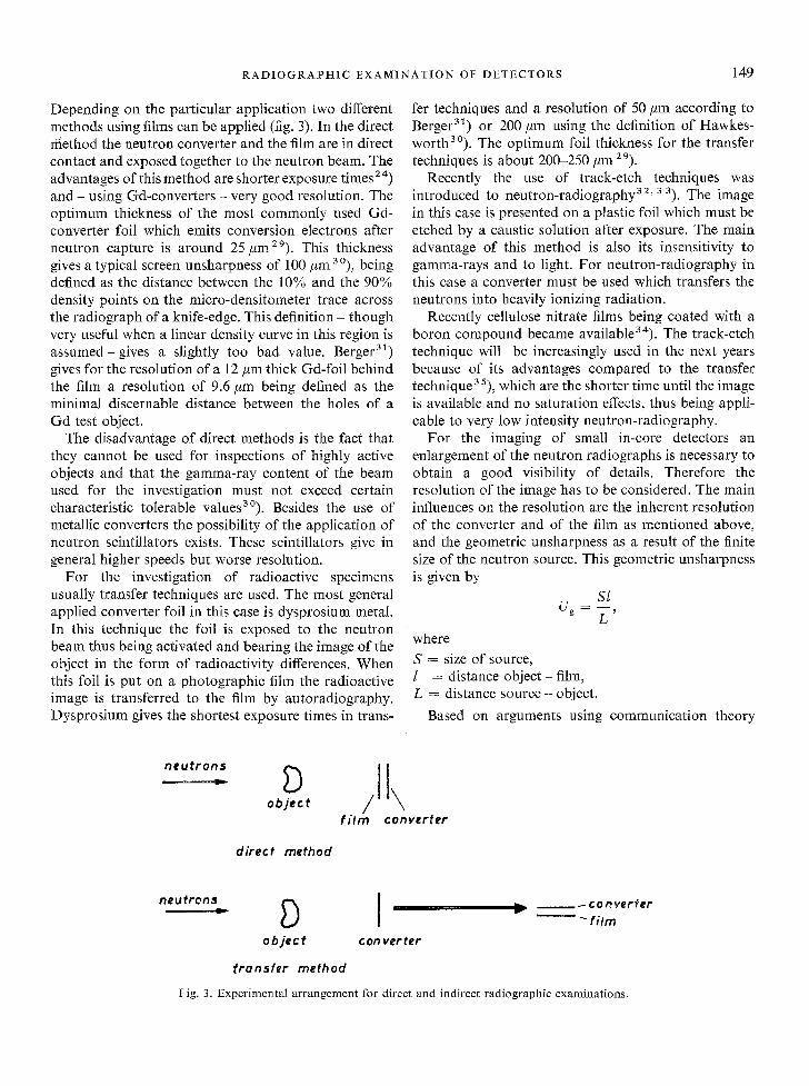
Depending on the particular application two different methods using films can be applied (fig. 3). In the direct ffiethod the neutron converter and the film are in direct contact and exposed together to the neutron beam. The advantages of this method are shorter exposure times z 4) and - using Gd-converters - very good resolution. The opt imum thickness of the most commonly used Gd- converter foil which emits conversion electrons after neutron capture is around 25 #m29). This thickness gives a typical screen unsharpness of 100 #m zo), being defined as the distance between the 10% and the 90% density points on the micro-densitometer trace across the radiograph of a knife-edge. This definit ion- though very useful when a linear density curve in this region is a s sumed-g ive s a slightly too bad value. Berger 31) gives for the resolution of a 12 pm thick Gd-foil behind the film a resolution of 9.6 #m being defined as the minimal discernable distance between the holes of a Gd test object.
The disadvantage of direct methods is the fact that they cannot be used for inspections of highly active objects and that the gamma-ray content of the beam used for the investigation must not exceed certain characteristic tolerable values3°). Besides the use of metallic converters the possibility of the application of neutron scintillators exists. These scintillators give in general higher speeds but worse resolution.
For the investigation of radioactive specimens usually transfer techniques are used. The most general applied converter foil in this case is dysprosium metal. In this technique the foil is exposed to the neutron beam thus being activated and bearing the image of the object in the form of radioactivity differences. When this foil is put on a photographic film the radioactive image is transferred to the film by autoradiography. Dysprosium gives the shortest exposure times in trans-
fer techniques and a resolution of 50 pm according to Berger 31) or 200 #m using the definition of Hawkes- worth 30). The opt imum foil thickness for the transfer techniques is about 200-250/~m 2 9).
Recently the use of track-etch techniques was introduced to neutron-radiography 3z' 3 3). The image in this case is presented on a plastic foil which must be etched by a caustic solution after exposure. The main advantage of this method is also its insensitivity to gamma-rays and to light. For neutron-radiography in this case a converter must be used which transfers the neutrons into heavily ionizing radiation.
Recently cellulose nitrate films being coated with a boron compound became available34). The track-etch technique will be increasingly used in the next years because of its advantages compared to the transfer technique 35), which are the shorter time until the image is available and no saturation effects, thus being appli- cable to very low intensity neutron-radiography.
For the imaging of small in-core detectors an enlargement of the neutron radiographs is necessary to obtain a good visibility of details. Therefore the resolution of the image has to be considered. The main influences on the resolution are the inherent resolution of the converter and of the film as mentioned above, and the geometric unsharpness as a result of the finite size of the neutron source. This geometric unsharpness is given by
SI Ug ~ - - ,
L
w h e r e
S = size of source, l = distance ob j ec t - film, L = distance s o u r c e - object.
Based on arguments using communication theory
obj,,t / \ f i lm converter
direct method
o.o,roo [ _ _.oov.,.r_,i,o object con verter
f ransfer method
Fig. 3. Experimental arrangement for direct and indirect radiographic examinations.
150 HELMUTH BI3CK AND ANTON ZEILINGER
Spiegler and N o r m a n 36) conc luded tha t the to ta l unsharpness is given as
u~ = ( ~ + v~o) ~, with Ufc the f i lm-conver te r unsharpness .
3. Experimental arrangement
The neut ron rad iographs were pe r fo rmed at the neu t ron - r ad iog raphy facili ty at the T R I G A - M a r k II reac tor Vienna. This facil i ty uses a divergent col l ima-
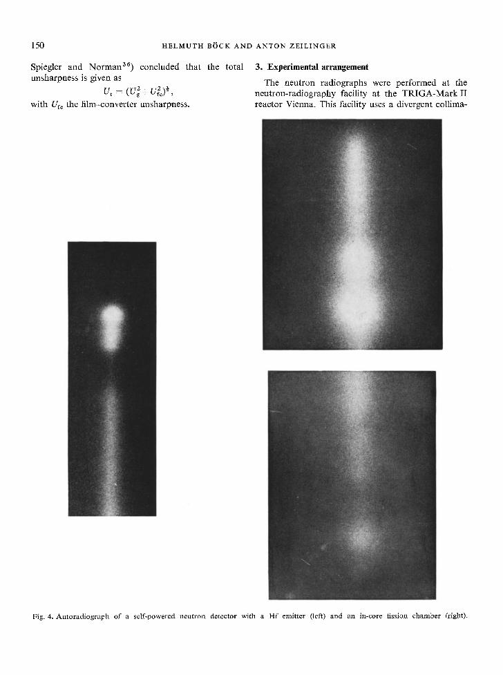
Fig. 4. Autoradiograph of a self-powered neutron detector with a Hf emitter (left) and an in-core fission chamber (right).

R A D I O G R A P H I C E X A M I N A T I O N OF D E T E C T O R S 151
Co-emitter H f-emitter Er-emitter Pt-emitter
Fig. 5. Indirect neu t ron rad iographs o f self-powered neu t ron detectors with different emit ter materials.
152 H E L M U T H BOCK AND A N T O N Z E I L I N G E R
" ;;i!', ' : ; : i ::?:i i }
Co-emitter H f-emitter Er-emitter Pt-emitter
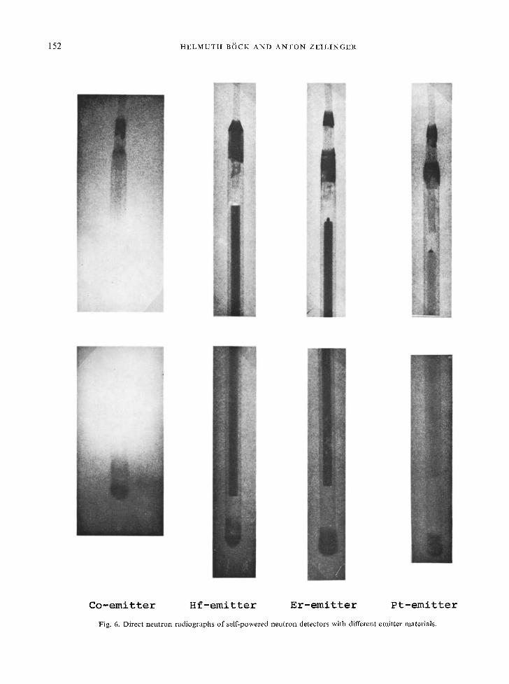
Fig. 6. Direct neutron radiographs o f self-powered neutron detectors with different emitter materials.

R A D I O G R A P H I C E X A M I N A T I O N OF DETECTORS 153
tor 3 v). The inner diameter and therefore the size of the neutron source was 15mm, the distance from the source to the image plane was 3 m and the distance from the object to the image plane was 2 cm. The
geometrical unsharpness was therefore approximately 0.1 ram. When the above mentioned resolution data of Berger 3t) are accepted, the local image unsharpness using Gd for the direct method is therefore approxi- mately 0.1 ram. If Dy is used for the transfer method the unsharpness increases to about 0.11 turn. Taking half of the value of Hawkesworts 3°) is a reasonable assumption. In this case the total unsharpness is 0.11 mm for Gd and 0.14 mm for Dy. This seems to be for our case the more realistic assumption, since the sharpness of the images using Gd and Dy is quite different. These considerations are quite important, because they influence the enlargement of the radio- graphs which can be achieved sensibly. In the present work it is not sensible to produce enlargements greater than a factor of two of the originals.
For the radiographs we used Osray TAT4 DW film, a Gd-converter of 0.025 mm thickness for the direct method and a Dy-converter of 0.100 mm thickness for the transfer method. The activation time of the Dy- converter was chosen to be 30rain in a thermal neutron flux of 6 x 10 s n/cm 2 s. This allows to take more than one autoradiographic copy of the same activated foil for different purposes. The neutron radiographs were enlarged on hard photographic paper which was developed using a document developer for enhancing the contrast. For control purposes we made some autoradiographs of the self- powered neutron detectors also with the same X-ray film and an exposure time of 10 rain. The exposure time for the direct method was 5 rain.
Fig. 7. Indirect neutron-radiography of an in-core fission chamber.
4. Results
For the investigations four self-powered neutron detectors and one fission chamber were available. All detectors had been exposed earlier to a neutron fluence of about 1 x 10¹⁹ n/cm 2 at steady state operation and to about 20 reactor power pulses with a peak neutron flux of 1 × 10¹⁶ n/cm ~ s 13,14). These irradiations resulted in a detector activation and in a gamma dose rate from 0.5 R/h (Pt-detector) to 3 R/h (Co-detector). Fig. 4. shows typical autoradiographs of the Hf- detector and of the fission chamber. The main activity of the Hf-detector is concentrated in the emitter and in the braze at the top of the detector, while at the fission chamber the position of the highly active uranium- coated electrode can be clearly distinguished.
Autoradiographs from an irradiated Co-detector are useless, because of the high detector activity, while the irradiated Pt-detector shows only a very weak picture due to its small activation.
Fig. 5 shows the result of the above mentioned
154 HELMUTH B/JCK AND ANION ZEILINGER
transfer me thod with conver ter foils. Al l pho tos reveal very clearly the emit ter as well as the cable and the braze between emit ter and cable. D a r k spots at bo th ends of the detectors are due to a neut ron- absorb ing braze (Ag-Cd) . As all four detectors were r ad iog raphed together a t the same t ime with the same neu t ron beam slight differences in the resolu t ion are due to beam inhomogenei t ies (i.e. lower pa r t o f the Pt-detector) .
Fig. 6 shows a set o f pho tos p roduced by direct neu t ron- rad iography . I t is evident that the resolu t ion is slightly bet ter for Hf-, Er- and Pt-detectors , because of their ra ther low activity. The Co-de tec tor shows a very interes t ing superpos i t ion o f neut ron- and gamma- au to rad iog raphy , thus reveal ing the advan tage o f indirect r ad iog raph ic me thods for highly active subjects.
Fig. 7 shows an indirect neu t ron r ad iog raph o f the minia ture in-core fission chamber . A t the upper pa r t of the pho to the cable, the me ta l - ce r amic seal and the e lect rode ho lder can be dis t inguished. The lower par t of the pic ture shows especial ly the a r r angemen t to fill the fission chamber with argon. The u ran ium-coa ted e lect rode extends f rom the me ta l - ce r amic seal down to the braze with an actual length o f a b o u t 40 mm. Just a long the outer j acke t a very fine da rk line can be seen in fig. 7 which represents the 93% enriched u ran ium layer.
The small g radua t ion in con t ras t pe rpend icu la r to the fission chamber axis in the lower pho to is caused by a ceramic a l ignment which keeps the e lect rode centred in the fission chamber . A small channel can be observed a long the axis which allows the gas to move freely between the active vo lume in the gas gap and the inactive vo lume inside the hol low electrode. The design and the test ing o f the same type o f fission chamber as used for our invest igat ions has been descr ibed in ref. 38.
In summary i t can be concluded tha t neut ron- r a d i o g r a p h y is a very va luable tool for the non- destruct ive invest igat ion of highly radioact ive compo- nents o f the reactor ins t rumenta t ion and safety system. Both methods , the direct and the indirect or t ransfer me thod can be app l ied accord ing to the specific p rob lem. The achieved reso lu t ion by neu t ron- rad io - g raphy allows to invest igate the physical in tegr i ty o f such cri t ical par t s o f in-core detectors like the emit ter or the electrode, the cable, the cable- to-de tec tor connec- t ion or the me ta l - ce r amic seal. As a non-des t ruct ive
me thod the invest igat ions can also be pe r fo rmed dur ing ex-core opera t ion or they can be repea ted after cer ta in intervals to analyze burn -up dependent effects.
References 1) USAEC-Standard RDT-C-15-4-T (2-72) (1972). 2) USAEC-Standard RDT-C-2-1-T (1970). 3) USAEC-Standard RDT-C-18-I-T (1970). 4) USAEC-Standard RDT-M-11-1-T (1969). 5) USAEC-Standard RDT-F-3-39-T (8-71) (1971). 6) A. Goodings, Nucl. Engng. 15 (1970) 599. 7) j. F. Boland, Nuclear radiation instrumentation (in-core)
(Gordon and Breach, 1970). s) E. Schrfifer, StrahlungundStrahlungsmefltechnikinKernkraft-
werken (Elitera Verlag, Berlin, 1974). 9) j. W. Hilborn, Nucleonics 22 (1964) 69.
10) C. W. Joslin, Nucl. Engng. 17 (1972) 399. tl) O. Strindehag, AE-440 (1971). t2) p. Gebureck, D. Stegemann, W. Jaschik and W. Seifritz,
Nuclear power plant control instrumentation, Proc. Symp., Prague, 1973 (IAEA, Vienna, 1973) p. 783.
la) H. B~Sck, P. Gebureck and D. Stegemann, Nucl. Instr. and Meth. 123 (1975) 117.
14) H. B/Sck, Nucl. Instr. and Meth. 125 (1975) 327. t5) R. Shields, IEEE Trans. NucI. Sci. NS-20 (1973) 603. 16) M. Brakas, O. Strindehag and B. S/Sderlund, Nucl. Engng.
18 (1973) 421. 17) E. Klar, S. Schaffer and H. G. Spfllekothen, Atomwirtschaft
19 (1974) 477. 12) W. Jeschki and R. Buehrer, Deutsche Reaktortagung
Berlin 1974, Kompaktband 594. 19) H. BSck, J. Nucl. Mat. 56 (1975) 85. z0) H. B6ck, E. Seidl and A. Zeilinger, J. Nucl. Mat. 54 (1974)
159. 21) L. D. Muhlestein and L. P. Philip, HEDL-TME-73-88 (1973). 22) j. Chin and C. W. Messick, GA-9118 (1973). 23) A. J. Patrick and S. D. Stoddard, LA-DC-6822 (1965). 24) H. Berger, Neutron radiography (Elsevier PuN. Co., Amster-
dam, London, New York, 1965). 25) W. A. Mayer, Kerntechnik 14 (1972) 343. 26) D. C. Cutforth, Nucl. Technol. 18 (1973) 67. 27) K. Chountas and H. Rauch, Atomkernenergie 13 (1968) 454. 2s) H. Berger and W. N. Beck, Nucl. Sci. Engng. 15 (1963) 411. 29) M. Miillner and H. Jex, Nucl. Instr. and Meth. 103 (1972) 229. 30) M. R. Hawkesworth, J. Sci. Instr. (J. Phys. E) 2 (1969) 235. 31) H. Berger, J. Appl. Phys. 34 (1963) 4. 32) S. C. Furman, R. W. Darmitzel, C. R. Porter and D. W.
Wilson, Trans. Am. Nucl Soc. 9 (1966). 33) H. Berger and I. R. Kraska, Trans. Am. Nucl. Soc. 10
(1967) 72. 34) Kodak-Path6 CA 80-15 type B film, available from J.
Barbier, Kodak-Path6, F-94300 Vincennes, France. 35) H. Berger, Nucl. Technol. 19 (1973) 188. 36) p. Spiegler and A. Norman, Phys. Med. Biol. 18 (1973) 884. 37) j. p. Barton, Materials Evaluation 25 (1967). 3s) W. Mayer, Kerntechnik 12 (1970) 388. 39) A. M. Ross, AECL, Chalk River, Ontario, Canada, private
communication.


![aesthesisudem.files.wordpress.com · Web viewAugustin Dumont et Aline Wiame (dir.).Bruxelles : P.I.E Peter Lang [2014] Lettres et sciences humaines : B 105 I47 I44 2014 Les ruines](https://static.fdocuments.us/doc/165x107/5f1e022dda89821d7b3b40af/web-view-augustin-dumont-et-aline-wiame-dirbruxelles-pie-peter-lang-2014.jpg)
