
NU773-8_ENG
223
DRIVER’S HANDBOOK TWINGO Ofrecido por www.electromanuales.com
-
Upload
patroleitor -
Category
Documents
-
view
218 -
download
0
Transcript of NU773-8_ENG

8/6/2019 NU773-8_ENG
http://slidepdf.com/reader/full/nu773-8eng 1/223
DRIVER’S HANDBOOK
TWINGO
Ofrecido por www.electromanuales.com

8/6/2019 NU773-8_ENG
http://slidepdf.com/reader/full/nu773-8eng 2/223
ELF is developing a complete range of
lubricants for RENAULT: engine oils, manual
and automatic transmission oils.
These are very high-technology
lubricants stimulated by applied
research in Formula One.
This range is updated with RENAULT’s
engineering teams to perfectly meet the
specific needs of RENAULT vehicles.
► ELF lubricants are a major factor in your
vehicle’s performance.
RENAULT recommends the approved ELF lubricants for your oil changes and top-ups.
Contact your RENAULT representative or visit the site: www.lubricants.elf.com
Important: to optimize engine operation the use of a lubricant
may be restricted to certain vehicles. Please refer to the
maintenance documentation.
recommends ELF
The oil born in Formula One
Ofrecido por www.electromanuales.com
8/6/2019 NU773-8_ENG
http://slidepdf.com/reader/full/nu773-8eng 3/223
0.1
Translated from French. Copying or translation, in part or in full, is forbidden unless prior written permission has been obtained from the vehicle manu-facturer.
This Driver’s Handbook contains the information necessary:
– for you to familiarise yourself with your vehicle, to use it to its best advantage and to benefit fully from the all the functions andthe technical developments it incorporates.
– to ensure that it always gives the best performance by following the simple, but comprehensive advice concerning regular main-tenance.
– to enable you to deal quickly with minor faults not requiring specialist attention.
It is well worth taking a few minutes to read this handbook to familiarise yourself with the information and guidelines it containsabout the vehicle and its functions and new features. If certain points are still unclear, our Network technicians will be only toopleased to provide you with any additional information.
The following symbol will help you when reading this handbook:
Welcome to your new vehicle
The descriptions of the models given in this handbook are based on the technical specifications at the time of writing. This hand-book covers all items of equipment (both standard and optional) available for these models but whether or not these arefitted to the vehicle depends on the version, options selected and the country where the vehicle is sold.
This handbook may also contain information about items of equipment to be introduced later in the model year.
Throughout the manual, the “approved Dealer” is your RENAULT Dealer.
To indicate a hazard, danger or safety recommendation.
Enjoy driving your new vehicle.
Ofrecido por www.electromanuales.com

8/6/2019 NU773-8_ENG
http://slidepdf.com/reader/full/nu773-8eng 4/223
0.2
Ofrecido por www.electromanuales.com

8/6/2019 NU773-8_ENG
http://slidepdf.com/reader/full/nu773-8eng 5/223
0.3
Getting to know your vehicle ...............................
Driving ...................................................................
Your comfort .........................................................
Maintenance .........................................................
Practical advice ....................................................
Technical specifications ......................................
Alphabetical index ...............................................
Sections
1
C O N T E N T S
2
3
4
5
6
7
Ofrecido por www.electromanuales.com
Of id l l

8/6/2019 NU773-8_ENG
http://slidepdf.com/reader/full/nu773-8eng 6/223
0.4
Ofrecido por www.electromanuales.com
Of id l l

8/6/2019 NU773-8_ENG
http://slidepdf.com/reader/full/nu773-8eng 7/223
1.1
Section 1: Getting to know your vehicle
Keys, Remote control: general information, use, deadlocking . . . . . . . . . . . . . . . . . . . . . . . . . . . . . 1.2Doors . . . . . . . . . . . . . . . . . . . . . . . . . . . . . . . . . . . . . . . . . . . . . . . . . . . . . . . . . . . . . . . . . . . . . . . . . 1.6Automatic locking when driving . . . . . . . . . . . . . . . . . . . . . . . . . . . . . . . . . . . . . . . . . . . . . . . . . . . . . 1.10Headrests . . . . . . . . . . . . . . . . . . . . . . . . . . . . . . . . . . . . . . . . . . . . . . . . . . . . . . . . . . . . . . . . . . . . . 1.11Front seats. . . . . . . . . . . . . . . . . . . . . . . . . . . . . . . . . . . . . . . . . . . . . . . . . . . . . . . . . . . . . . . . . . . . . 1.13Seat belts. . . . . . . . . . . . . . . . . . . . . . . . . . . . . . . . . . . . . . . . . . . . . . . . . . . . . . . . . . . . . . . . . . . . . . 1.16Methods of restraint in addition to the seat belts . . . . . . . . . . . . . . . . . . . . . . . . . . . . . . . . . . . . . . . . 1.20Child safety: general information . . . . . . . . . . . . . . . . . . . . . . . . . . . . . . . . . . . . . . . . . . . . . . . . . . . . 1.27
Choosing a child/baby seat mounting . . . . . . . . . . . . . . . . . . . . . . . . . . . . . . . . . . . . . . . . . . 1.30Fitting a child seat . . . . . . . . . . . . . . . . . . . . . . . . . . . . . . . . . . . . . . . . . . . . . . . . . . . . . . . . . 1.33Deactivating/activating the front passenger air bag . . . . . . . . . . . . . . . . . . . . . . . . . . . . . . . . 1.40
Driving position . . . . . . . . . . . . . . . . . . . . . . . . . . . . . . . . . . . . . . . . . . . . . . . . . . . . . . . . . . . . . . . . . 1.42Instrument panel . . . . . . . . . . . . . . . . . . . . . . . . . . . . . . . . . . . . . . . . . . . . . . . . . . . . . . . . . . . . . . . . 1.46
Trip computer and warning system . . . . . . . . . . . . . . . . . . . . . . . . . . . . . . . . . . . . . . . . . . . . 1.51
Steering wheel . . . . . . . . . . . . . . . . . . . . . . . . . . . . . . . . . . . . . . . . . . . . . . . . . . . . . . . . . . . . . . . . . . 1.54Time and external temperature . . . . . . . . . . . . . . . . . . . . . . . . . . . . . . . . . . . . . . . . . . . . . . . . . . . . . 1.55Door mirrors. . . . . . . . . . . . . . . . . . . . . . . . . . . . . . . . . . . . . . . . . . . . . . . . . . . . . . . . . . . . . . . . . . . . 1.57Exterior lighting and signals. . . . . . . . . . . . . . . . . . . . . . . . . . . . . . . . . . . . . . . . . . . . . . . . . . . . . . . . 1.58Headlight beam adjustment . . . . . . . . . . . . . . . . . . . . . . . . . . . . . . . . . . . . . . . . . . . . . . . . . . . . . . . . 1.62Audible and visual signals . . . . . . . . . . . . . . . . . . . . . . . . . . . . . . . . . . . . . . . . . . . . . . . . . . . . . . . . . 1.63Screen washer/wiper . . . . . . . . . . . . . . . . . . . . . . . . . . . . . . . . . . . . . . . . . . . . . . . . . . . . . . . . . . . . . 1.64Fuel tank . . . . . . . . . . . . . . . . . . . . . . . . . . . . . . . . . . . . . . . . . . . . . . . . . . . . . . . . . . . . . . . . . . . . . . 1.67
Ofrecido por www.electromanuales.com
Of id l t l

8/6/2019 NU773-8_ENG
http://slidepdf.com/reader/full/nu773-8eng 8/223
1.2
Key A 1 Coded key for ignition switch,
doors and fuel filler cap.
Radio frequency remotecontrol B
2 Locking the doors and tailgate.3 Unlocking the doors and tailgate.
4 Coded key for ignition switch, driv-er’s door and fuel filler cap.
Driver’ reonibility
Never leave your vehiclewith the card inside thevehicle and never leave a
child (or a pet) unsupervised. Withthe card in the reader, it would bepossible to start the engine or oper-ate electrical equipment such as theelectric windows and there is a riskthat part of their body may becometrapped (neck, arm, hand, etc.).
Risk of serious injury.
B
2
3
4
1
A
Advice
Avoid leaving the remote control inhot, cold or humid areas.
The key must not be used for anyfunction other than those describedin the handbook (removing the capfrom a bottle, etc.).
KEY/RADIO FREQUENCY REMOTE CONTROL: general information (1/2)Ofrecido por www.electromanuales.com
Of id l t l

8/6/2019 NU773-8_ENG
http://slidepdf.com/reader/full/nu773-8eng 9/223
1.3
KEY/RADIO FREQUENCY REMOTE CONTROL: general information (2/2)
Radio frequency remotecontrol oerating range
This varies according to the environ-ment. It is therefore important whenhandling the remote control to ensurethat you do not lock or unlock the ve-
hicle by inadvertently pressing the but-tons.
Note: on certain vehicles, if a door isnot opened within approximately 2 min-utes of the door being unlocked byremote control, the doors will lock againautomatically.
Interference
The presence of certain objects (metalobjects, mobile telephones, or an areawith strong electromagnetic radiation,etc.) close to the key may create inter-ference and affect the operation of thesystem.
Relacement and additional key
or remote control.You must only contact an approveddealer:
– If you need to replace a key it willbe necessary to take the vehicleand all of its keys to an approvedDealer in order to initialise thesystem.
– Depending on the vehicle, you
have the option of using up tofour remote controls.
Remote control unit failure
Make sure that the correct batterytype is being used, and that thebattery is in good condition and in-serted correctly. These batterieshave a service life of approximately
two years.Refer to Section 5: “Radio fre-quency remote control: batteries”for the battery changing procedure.
Ofrecido por www.electromanuales.com
Ofrecido por www electromanuales com

8/6/2019 NU773-8_ENG
http://slidepdf.com/reader/full/nu773-8eng 10/223
1.4
RADIO FREQUENCY REMOTE CONTROL: ue
Doors are locked and unlocked usingremote control unit B.
It is powered by a battery which mustbe replaced (refer to the information onthe “Radio frequency remote control:batteries” in Section 5).
Locking te doorPress locking button 1.
The hazard warning lights and side in-dicator lights fla twice to indicatethat the doors have locked.
If a door or the tailgate is open or notproperly shut, the doors and tailgatelock then quickly unlock and the hazardwarning lights and side indicator lights
do not flash.
Unlocking te doorPress unlocking button 2 .
The hazard warning lights and side in-dicator lights fla once to indicate thatthe doors have unlocked.
B
1
B
2
Ofrecido por www.electromanuales.com
Ofrecido por www electromanuales com

8/6/2019 NU773-8_ENG
http://slidepdf.com/reader/full/nu773-8eng 11/223
1.5
DEADLOCKING
Deadlocking of te door/tailgate(for some countries)
This allows you to lock the doors andtailgate and to prevent the doors frombeing opened with the interior handles(by breaking the window and then tryingto open the doors from the inside).
Never use deadlocking if someone is still inside thevehicle.
1
To activate deadlocking
Press button 1 twice in quick succes-sion.
The hazard warning lights and side in-dicator lights flash five times to indicatethat the doors have locked.
Ofrecido por www.electromanuales.com
Ofrecido por www electromanuales com

8/6/2019 NU773-8_ENG
http://slidepdf.com/reader/full/nu773-8eng 12/223
1.6
OpENING AND CLOsING ThE DOORs
Manual lockingOening manually from te inidePull handle 1.
Ligt-on warning buzzer
If you have left the lights on after switch-ing off the ignition, a reminder buzzer will sound when the driver’s door or, de-pending on the vehicle, the front doorsor tailgate are opened (to prevent dis-
charge of the battery, etc.).
Oening manually from te outide
With the key, unlock the front door lock 2 . Place your hand under handle 3.Lift the handle and then pull the door towards you.
Driver’ reonibilityIf you decide to keep thedoors locked when you aredriving, remember that it
may be more difficult for those as-sisting you to gain access to thepassenger compartment in theevent of an emergency.
1
2
3
Driver’ reonibility wen arking or toing te veicle
Never leave an animal, child or adult who is not self-sufficient alone onyour vehicle, even for a short time.They may pose a risk to themselves or to others by starting the engine,
activating equipment such as the electric windows or by locking the doors.Also, in hot and/or sunny weather, please remember that the temperature insidethe passenger compartment increases very quickly.RIsK OF DEATh OR sERIOUs INJURY.
Ofrecido por www.electromanuales.com
LOCKING/UNLOCKING ThE DOORsOfrecido por www electromanuales com

8/6/2019 NU773-8_ENG
http://slidepdf.com/reader/full/nu773-8eng 13/223
1.7
SElectric central locking(depending on vehicle)
It simultaneously locks or unlocks thedoors and the tailgate.
Lock or unlock by pressing switch 1.
The doors cannot be locked/unlockedwith a door open.
If a door is open or not properly closed,the doors lock and then quickly unlock.
Door and tailgate tatuindicator ligt
Te indicator ligt on witc 1 inform you of te cloure tatu of te door and tailgate:
– the indicator light is on when thedoors/tailgate are locked;
– the indicator light goes out when adoor or the tailgate is open (or incor-rectly closed).
When you lock the doors using theremote control, the indicator light re-mains lit for approximately one minutethen goes out.
LOCKING/UNLOCKING ThE DOORs (1/3)
If you decide to keep thedoors locked when youare driving, remember thatit may be more difficult for
those assisting you to gain accessto the passenger compartment inthe event of an emergency.
Locking te door manually
With the door open, turn screw 2 (usinga tool such as a flat-blade screwdriver)and close the door.
This means that the doors are thenlocked from the outside.
The doors may then only be openedfrom the inside or by using the key inthe left-hand door.
Never leave your vehiclewith the key inside.
1
2
Ofrecido por www.electromanuales.com
LOCKING/UNLOCKING ThE DOORs (2/3)Ofrecido por www electromanuales com

8/6/2019 NU773-8_ENG
http://slidepdf.com/reader/full/nu773-8eng 14/223
1.8
LOCKING/UNLOCKING ThE DOORs (2/3)
Electric central locking
Locking/unlocking from te outide
In some cases, the radio frequencyremote control may not work:
– if the vehicle is located in a zone of
high electromagnetic radiation; – if appliances are operating on the
same frequency as the remote con-trol (mobile phone, etc.);
– if the remote control battery is wornor flat, etc.
Unlocking te door andtailgate
Uing te radio frequency remotecontrol (refer to te information onte “Key/Radio frequency remotecontrol” in section 1).
From the outside, unlock the driver’sdoor using the coded ignition key (refer to Section 1: “Opening/Closing the
doors”).
Never leave your vehiclewith the key inside.
1
Ofrecido por www.electromanuales.com
LOCKING/UNLOCKING ThE DOORs (3/3)Ofrecido por www.electromanuales.com

8/6/2019 NU773-8_ENG
http://slidepdf.com/reader/full/nu773-8eng 15/223
1.9
LOCKING/UNLOCKING ThE DOORs (3/3)
Press switch 1 for more than five sec-onds, then get out of the vehicle withthe remote control with you and closethe driver’s door.
When the door is closed, all the doorsand the tailgate will be locked.
The vehicle can only be unlocked fromthe outside with the coded ignition key,for the front left-hand door.
Make ure you ave your remotecontrol wit you before you leaveyour veicle.
Locking te door andtailgate
Uing te door locking/unlocking in-terior control.
With the engine off and the driver’sdoor open, switch on the ignition andswitch it off again.
Driver’ reonibility
Never leave your vehiclewith the key inside.
If you decide to keep the doorslocked when you are driving, re-member that it may be more diffi-cult for those assisting you to gainaccess to the passenger compart-ment in the event of an emergency.
1
Ofrecido por www.electromanuales.com
AUTOMATIC LOCKING WhEN DRIVINGOfrecido por www.electromanuales.com

8/6/2019 NU773-8_ENG
http://slidepdf.com/reader/full/nu773-8eng 16/223
1.10
AUTOMATIC LOCKING WhEN DRIVING
You can decide weter you want toactivate ti function.
To activate
Wit te ignition on, press centraldoor locking button 1 for about 5 sec-onds, until a double beep is heard.
To deactivate
With the ignition on, press central door locking button 1 for about five seconds,until a double beep is heard.
If you decide to keep thedoors locked when youare driving, remember thatit may be more difficult for
those assisting you to gain accessto the passenger compartment inthe event of an emergency.
Oerating rincile
When the vehicle is started, the systemautomatically locks the doors assoon as a speed of 4 mph (7 km/h) isreached.
The button’s indicator light 1 comes on.
The door can be unlocked:
– by opening a door when stationary.
Note: if a door is opened, it will auto-matically be locked again when thevehicle reaches a speed of approxi-mately 4 mph (7 km/h);
– by pressing the door unlockingbutton 1.
Oerating fault
If you find an operating fault (no au-tomatic locking, the indicator light for button 1 does not light up when tryingto lock the doors and tailgate, etc.),
firstly check that the doors and tailgateare properly closed. If they are properlyclosed and the fault is still present, con-tact an approved Dealer.
1
Ofrecido por www.electromanuales.com
FRONT hEADREsTs (1/2)Ofrecido por www.electromanuales.com

8/6/2019 NU773-8_ENG
http://slidepdf.com/reader/full/nu773-8eng 17/223
1.11
FRONT hEADREsTs (1/2)
The headrest is a safetycomponent. Ensure that it isfitted and in the correct po-sition: the top of your head
should be in line with the top of theheadrest.
Fixed, non-adjutableeadret A
To raie te eadret
Press button 1 and lift the headrest torelease it.
To refit te eadret
Insert the headrest rods into the holes(tilt the seatback backwards if neces-
sary).Push the headrest in until it locks in po-sition.
Headrest A is fixed and its heightcannot be adjusted.
Adjuting te eadret(depending on the vehicle)
1
A
p
FRONT hEADREsTs (2/2)Ofrecido por www.electromanuales.com

8/6/2019 NU773-8_ENG
http://slidepdf.com/reader/full/nu773-8eng 18/223
1.12
FRONT hEADREsTs (2/2)
heigt adjutable eadret BIt can be identified by the presence of button 2 .
To raie te eadret
Slide it upwards to the required height.
To lower te eadret
Press button 2 and guide the headrestdown to the desired height.
To raie te eadret
Raise the headrest to its highest po-sition (tilt the seatback backwards if necessary). Press button 1 and lift theheadrest to release it.
Note: when the headrest is removed,take care not to change the positionsof rods 3.
To refit te eadret
In case the adjustment of the rods hasbeen modified, pull out the rods 3 as far as they will go (ensure they are alignedand clean). In case of difficulty, ensurethe notches face forwards.
Insert the headrest rods into the holes(tilt the seatback backwards if neces-sary).Lower the headrest until it locks, pressbutton 2 and lower the headrest as far as possible.Check that each rod is securelylocked 3.
2
B
1
B
3
p
FRONT sEATs (1/3) Ofrecido por www.electromanuales.com

8/6/2019 NU773-8_ENG
http://slidepdf.com/reader/full/nu773-8eng 19/223
1.13
FRONT sEATs (1/3)
To move forward or backward
Move the lever 2 or handle 4 (passen-ger side) to unlock. Once in the desiredposition, release the lever or handleand check that the seat is correctlylocked.
To tilt te eatbackMove handle 5 and tilt the seatback tothe desired position.
heated eat(depending on the vehicle)
With the ignition switched on, pressswitch 1 on the required seat. The indi-cator light in the switch lights up.The system, which has a thermostat,regulates the heating and deactivates itif necessary.
Adjuting te eigt of tedriver’ eat(depending on the vehicle)
Move lever 3.
For safety reasons, carry out any adjustments when the vehicle is notbeing driven.
We would advise you not to recline the seatbacks too far to ensure thatthe effectiveness of the seat belts is not reduced.
Nothing should be placed on the floor (area in front of driver) as such objects mayslide under the pedal during braking manoeuvres, thus obstructing its use. Make sure that the seat-
backs are correctly lockedin place.
1
2
3
4
5
p
FRONT sEATs (2/3) Ofrecido por www.electromanuales.com

8/6/2019 NU773-8_ENG
http://slidepdf.com/reader/full/nu773-8eng 20/223
1.14
FRONT sEATs (2/3)
Table function
Depending on the vehicle, the passen-ger seatback may be folded down ontothe seat base to create a table:
– lower headrest6 ;
– move handle4 and move the seatback fully;
– fold the seatback and move theseat forwards to position headrest 6
under the dashboard.
When placing the frontseatback in the table posi-tion, it is essential to deac-tivate the passenger air bag
(refer to Section 1: “Deactivating thefront passenger air bag”).
Risk of serious injuries from ob- jects thrown from the seatback tablewhen the air bags deploy.
The label (on the dashboard) andthe markings (on the sun visor)remind you of these instructions.
When driving, rear passen-gers must not place their feet on the seatback of thefront seats under any cir-
cumstances. Risk of injury.
For your safety, attach anytransported objects whenthe seat is in the table po-sition.
6
4
6
FRONT sEATs (3/3) Ofrecido por www.electromanuales.com

8/6/2019 NU773-8_ENG
http://slidepdf.com/reader/full/nu773-8eng 21/223
1.15
O s s ( )
Acce to te rear eat
Move handle 4, 7 or 8 (depending onvehicle), tilt the seatback and slide theseat forwards.
To return the seat to its original (stored)position on the driver’s side, slide theseat backwards until it locks.
For safety reasons, carryout any adjustments whenthe vehicle is not beingdriven.
We would advise you not to reclinethe seatbacks too far to ensure thatthe effectiveness of the seat belts isnot reduced.
Nothing should be placed on the
floor (area in front of driver) as suchobjects may slide under the pedalduring braking manoeuvres, thusobstructing its use.
Make sure that the seatbacks arecorrectly locked in place.
Check that no object or person prevents the frontseat from locking. If so,remove any obstacles
behind the front seats. Adjust theseat to allow sufficient room in therear. The rear occupants/objectsshould then return to the vehicle.
Repeat the above until the seat islocked correctly.
Risk of seat moving on its runnersduring vehicle acceleration or brak-ing.
Do not move handle 2 andhandle 4,7 or 8 at the same time.
47
2
8
sEAT BELTs (1/2) Ofrecido por www.electromanuales.com
8/6/2019 NU773-8_ENG
http://slidepdf.com/reader/full/nu773-8eng 22/223
1.16
( )
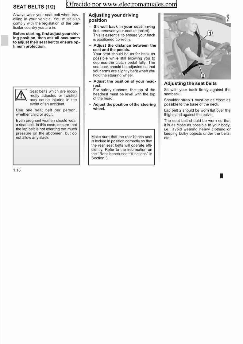
Always wear your seat belt when trav-elling in your vehicle. You must alsocomply with the legislation of the par-ticular country you are in.
Before tarting, firt adjut your driv-ing oition, ten ak all occuantto adjut teir eat belt to enure o-timum rotection.
Adjuting your drivingoition
– sit well back in your eat (havingfirst removed your coat or jacket).This is essential to ensure your backis positioned correctly.
– Adjut te ditance between teeat and te edal.Your seat should be as far back aspossible while still allowing you todepress the clutch pedal fully. Theseatback should be adjusted so thatyour arms are slightly bent when youhold the steering wheel.
– Adjut te oition of your ead-
ret.For safety reasons, the top of theheadrest must be level with the topof the head.
– Adjut te oition of te teeringweel.
Adjuting te eat belt
Sit with your back firmly against theseatback.
Shoulder strap 1 must be as close aspossible to the base of the neck.
Lap belt 2 should be worn flat over thethighs and against the pelvis.
The seat belt should be worn so thatit is as close as possible to your body,
i.e.: avoid wearing heavy clothing or keeping bulky objects under the belts,etc.Make sure that the rear bench seat
is locked in position correctly so thatthe rear seat belts will operate effi-ciently. Refer to the information onthe “Rear bench seat: functions” inSection 3.
Seat belts which are incor-rectly adjusted or twistedmay cause injuries in theevent of an accident.
Use one seat belt per person,whether child or adult.
Even pregnant women should wear a seat belt. In this case, ensure that
the lap belt is not exerting too muchpressure on the abdomen, but donot allow any slack.
1
2
sEAT BELTs (2/2) Ofrecido por www.electromanuales.com

8/6/2019 NU773-8_ENG
http://slidepdf.com/reader/full/nu773-8eng 23/223
1.17
( )
Locking
Unwind the belt lowly and mootly and ensure that buckle 3 locks intocatch 5 (check that it is locked by pull-ing on buckle 3).
If the belt jams, allow it to return slightlybefore attempting to unwind it again.
If your seat belt becomes completely jammed:
– pull the belt slowly but firmly so that just over 3 cm unwinds;
– then allow the seat belt to rewind au-tomatically;
– unwind it again; – if there is still a problem, contact an
approved Dealer.
ç Driver eat beltreminder warning ligt
This lights up if the driver’s seat beltis not fastened and, when the vehicle
reaches a speed of approximately 6mph (10 km/h), it flashes and a beepsounds for approximately 2 minutesbefore the light returns to being contin-uously lit.
Unlocking
Press button 4 on buckle 5 and the seatbelt will be rewound by the inertia reel.
Guide the buckle to help the operation.
3 4
5
5
REAR sEAT BELTs Ofrecido por www.electromanuales.com

8/6/2019 NU773-8_ENG
http://slidepdf.com/reader/full/nu773-8eng 24/223
1.18
Rear ide eat belt
The belts are locked, unlocked andadjusted in the same way as the frontbelts.
Rear eat function:
Refer to the information on the“Rear seats: functions” in Section 3.
Slowly unwind belt 1.
Click buckle 2 into the catch 3.
Check that the rear seatbelts are positioned and op-erating correctly each timethe rear seats are moved.
1
2
3
sEAT BELTs
Ofrecido por www.electromanuales.com

8/6/2019 NU773-8_ENG
http://slidepdf.com/reader/full/nu773-8eng 25/223
1.19
Te following information alie to te veicle’ front and rear eat belt. – No modification may be made to the component parts of the restraint system (belts and seats and their mountings)
fitted originally. For special operations (e.g. fitting child seats) contact an approved Dealer.
– Do not use devices which allow any slack in the belts (e.g. clothes pegs, clips, etc.): a seat belt which is worn tooloosely may cause injury in the event of an accident.
– Never wear the shoulder strap under your arm or behind your back.
– Never use the same belt for more than one person and never hold a baby or child on your lap with your seat belt aroundthem.
– The belt should never be twisted.
– Following an accident, have the seat belts checked and replaced if necessary. Always replace your seat belts as soon asthey show any signs of wear.
– When putting back the rear bench seat, take care that the seat belts are correctly positioned so that they can be used prop-erly.
– Make sure that the buckle is inserted into the appropriate catch.
– Ensure that no objects are placed in the area around the seat belt catch as they could prevent it from being properly se-cured.
METhODs OF REsTRAINT IN ADDITION TO ThE FRONT sEAT BELTs (1/4)Ofrecido por www.electromanuales.com

8/6/2019 NU773-8_ENG
http://slidepdf.com/reader/full/nu773-8eng 26/223
1.20
These are:
– retenioner;
– force limiter;
– air bag for driver and front a-enger;
– ide air bag (deending on vei-cle).
These systems are designed to operateindependently or together in the eventof a front, side or rear impact.
Depending on the severity of theimpact, the system can trigger:
– seat belt locking;
– the buckle pretensioner (which en-gages to correct seat belt slack);
– the air bags.
pretenioner
With the ignition switched on, if the ve-hicle is subjected to a significant fron-tal impact the system may, dependingon the severity of the impact, trigger piston 1 which instantly retracts thebelt.
The pretensioners hold the seat beltagainst the body, holding the occupantmore securely against the seat, thus in-
creasing the seat belt’s efficiency.
– Have the entire restraintsystem checked followingan accident.
– No operation whatso-ever is permitted on any part of the system (pretensioners, air
bags, computers, wiring) and thesystem components must notbe reused on any other vehicle,even if identical.
– To avoid incorrect triggering of the system which may causeinjury, only qualified personnelfrom an approved dealer maywork on the pretensioner and air bag system.
– The electric trigger system mayonly be tested by a speciallytrained technician using specialequipment.
– When the vehicle is scrapped,contact an approved dealer for disposal of the pretensioner andair bag gas generators.
1
METhODs OF REsTRAINT IN ADDITION TO ThE FRONT sEAT BELTs (2/4)Ofrecido por www.electromanuales.com

8/6/2019 NU773-8_ENG
http://slidepdf.com/reader/full/nu773-8eng 27/223
1.21
Force limiter
Above a certain severity of impact, thismechanism is used to limit the force of the belt against the body so that it is atan acceptable level.
Air bag for driver and frontaenger
Fitted to the driver and passenger side.
The presence of this equipment is in-dicated by the word “Air bag” on thesteering wheel and the dashboard (air
bag zone A) and a label on the lower part of the windscreen or on the sunvisor.
Each air bag system consists of:
– an air bag and gas generator fittedon the steering wheel for the driver and in the dashboard for the frontpassenger;
– a shared computer, which includesthe impact detector and the moni-tor controlling the electrical trigger system for each of the gas genera-tors;
– depending on the vehicle, an addi-tional side impact detector;
– a singleå warning light on theinstrument panel.
The air bag system usespyrotechnic principles. Thisexplains why, when the air bag inflates, it will gener-
ate heat, produce smoke (this doesnot mean that a fire is about to start)
and make a noise upon detonation.In a situation where an air bag isrequired, it will inflate immediatelyand this may cause some minor, su-perficial grazing to the skin or other problems.
A
METhODs OF REsTRAINT IN ADDITION TO ThE FRONT sEAT BELTs (3/4)Ofrecido por www.electromanuales.com

8/6/2019 NU773-8_ENG
http://slidepdf.com/reader/full/nu773-8eng 28/223
1.22
Oeration
The air bag system is only operationalwhen the ignition is switched on.
If a severe frontal impact occurs, theair bag(s) deploy(s) rapidly, cushion-ing the impact of the driver’s head andchest against the steering wheel andthe front passenger’s head against thedashboard. The air bag then deflatesimmediately so that passengers are not
impeded in any way when they get outof the vehicle.
Oerating fault
Warning light 2 å will light up onthe instrument panel when the ignitionis switched on and then go out after afew seconds.
If it does not light up when the ignition isswitched on, or comes on continuouslywhen the engine is running, there is afault in the system.
Contact your approved Dealer as soonas possible. Your protection will be re-duced until this fault is rectified.
2
METhODs OF REsTRAINT IN ADDITION TO ThE FRONT sEAT BELTs (4/4)Ofrecido por www.electromanuales.com

8/6/2019 NU773-8_ENG
http://slidepdf.com/reader/full/nu773-8eng 29/223
1.23
All of te warning below are given o tat te air bag i not obtructed in any way wen it i deloyed and alo to re-vent te rik of eriou injurie caued by item wic may be dilodged wen te air bag deloy.
Warning concerning te driver’ air bag
– Do not modify the steering wheel or the steering wheel boss. – Do not cover the steering wheel boss under any circumstances.
– Do not attach any objects (badge, logo, clock, telephone holder, etc.) to the steering wheel boss. – The steering wheel must not be removed (except by qualified personnel from our Network). – When driving, do not sit too close to the steering wheel. Sit with your arms slightly bent (see the information on “Adjusting
your driving position” in Section 1). This will allow sufficient space for the air bag to deploy correctly and be fully effective.
Warning concerning te aenger air bag
– Do not attach or glue any objects (badge, logo, clock, telephone holder, etc.) to the dashboard on or near the air bag. – Do not place anything between the dashboard and the passenger (pet, umbrella, walking stick, parcels, etc.). – The passenger must not put his or her feet on the dashboard or seat as there is a risk that serious injuries may occur. In
general, parts of the body should be kept away from the dashboard (knees, hands, head, etc.).
– The systems in addition to the front passenger seat belt should be reactivated as soon as a child seat is removed, to ensurethe protection of the passenger in the event of an impact.
A REAR-FACING ChILD sEAT MUsT NOT BE FITTED TO ThE FRONT pAssENGER sEAT UNLEssThE ADDITIONAL REsTRAINT sYsTEMs, I.E. ThE pAssENGER AIR BAG, ARE DEACTIVATED.
(Refer to Section 1 “Child safety: deactivating/activating the front passenger air bag”).
METhODs OF REsTRAINT IN ADDITION TO ThE REAR sEAT BELTsOfrecido por www.electromanuales.com

8/6/2019 NU773-8_ENG
http://slidepdf.com/reader/full/nu773-8eng 30/223
1.24
Force limiter
Above a certain severity of impact, thismechanism is used to limit the force of the belt against the body so that it is atan acceptable level.
– Have the entire restraintsystem checked followingan accident.
– No operation whatsoever is permitted on any part of thesystem (air bags, electronic con-trol units, wiring) and the systemcomponents must not be reusedon any other vehicle, even if iden-tical.
– To avoid incorrect triggering of the system which may causeinjury, only qualified RENAULTNetwork personnel may workon the pretensioner and air bagsystem.
sIDE pROTECTION DEVICEsOfrecido por www.electromanuales.com

8/6/2019 NU773-8_ENG
http://slidepdf.com/reader/full/nu773-8eng 31/223
1.25
side air bag
These air bags may be fitted to the frontseats and are deployed at the sides of the seats (door side) to protect the oc-cupants in the event of a severe sideimpact.
A marking on the seat informs you of the presence of this device.
Curtain air bag
These air bags may be fitted along thetop of each side of the vehicle and aretriggered along the front and rear sidewindows to protect passengers in theevent of a side impact.
A marking on the interior trim above theside windows informs you of the pres-ence of this device.
Warning concerning te ide air bag
– Fitting eat cover: seats equipped with an air bag require coversspecifically designed for your vehicle. Contact an approved Dealer to findout if these covers are available. The use of any covers other than those
designed for your vehicle (and including those designed for another vehicle)may affect the operation of the air bags and reduce your protection.
– Do not place any accessories, objects or even pets between the seatback, thedoor and the internal fittings. Do not cover the seatback with any items such asclothes or accessories. This may prevent the air bag from operating correctlyor cause injury when the air bag is deployed.
– No work or modification whatsoever may be carried out on the seat or internalfittings, except by qualified personnel from an approved dealer.
– The area between the rear bench seatback and the trim is the area of air bagoperation: no objects must be placed here.
All f t i b l i t t t i b i t b t t d i it i d l d d l t
ADDITIONAL METhODs OF REsTRAINTOfrecido por www.electromanuales.com

8/6/2019 NU773-8_ENG
http://slidepdf.com/reader/full/nu773-8eng 32/223
1.26
The air bag is designed to complement the action of the seat belt. The air bag and the seat belt are integral parts of the same protection system. It is therefore essential to wear the seat belt at all times. If seat belts are not worn, the oc-cupants are exposed to the risk of serious injury in the event of an accident. It may also increase the risk of minor su-perficial injuries occurring when the air bag is deployed, although such minor injuries are always possible with air bags.
If the vehicle should overturn or suffer a rear impact, however severe, the pretensioners and air bags are not always triggered.Impacts to the underside of the vehicle from pavements, holes, stones etc. can all trigger these systems.
– No work or modification watoever may be carried out on any part of the driver or passenger air bag system (air bags,pretensioners, electronic unit, wiring harness, etc., except by qualified RENAULT network personnel);
– To ensure that the system is in good working order and to avoid accidental triggering of the system which may cause injury,only qualified RENAULT Network personnel may work on the air bag system;
– As a safety precaution, have the air bag system checked if your vehicle has been involved in an accident, or is stolen or broken into;
– When selling or lending the vehicle, inform the user of these points and hand over this driver’s handbook with the vehicle;
– When scrapping your vehicle, contact your RENAULT Dealer for disposal of the gas generator(s).
All of te warning below are given o tat te air bag i not obtructed in any way wen it i deloyed and alo to re-vent te rik of eriou injurie caued by item wic may be dilodged wen te air bag deloy.
C i ild
ChILD sAFETY: General information (1/2)Ofrecido por www.electromanuales.com
8/6/2019 NU773-8_ENG
http://slidepdf.com/reader/full/nu773-8eng 33/223
1.27
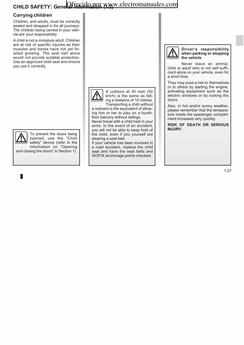
Carrying cildren
Children, and adults, must be correctlyseated and strapped in for all journeys.The children being carried in your vehi-cle are your responsibility.
A child is not a miniature adult. Children
are at risk of specific injuries as their muscles and bones have not yet fin-ished growing. The seat belt alonewould not provide suitable protection.Use an approved child seat and ensureyou use it correctly.
To prevent the doors beingopened, use the “Childsafety” device (refer to theinformation on “Opening
and closing the doors” in Section 1).
A collision at 30 mph (50km/h) is the same as fall-ing a distance of 10 metres.Transporting a child without
a restraint is the equivalent of allow-ing him or her to play on a fourth-floor balcony without railings.Never travel with a child held in your arms. In the event of an accident,
you will not be able to keep hold of the child, even if you yourself arewearing a seat belt.If your vehicle has been involved ina road accident, replace the childseat and have the seat belts andISOFIX anchorage points checked.
Driver’ reonibilitywen arking or toingte veicle
Never leave an animal,child or adult who is not self-suffi-cient alone on your vehicle, even for a short time.
They may pose a risk to themselves
or to others by starting the engine,activating equipment such as theelectric windows or by locking thedoors.
Also, in hot and/or sunny weather,please remember that the tempera-ture inside the passenger compart-ment increases very quickly.
RIsK OF DEATh OR sERIOUs
INJURY.
ChILD sAFETY: General information (2/2)
Uing a cild eat
Ofrecido por www.electromanuales.com

8/6/2019 NU773-8_ENG
http://slidepdf.com/reader/full/nu773-8eng 34/223
1.28
Uing a cild eatThe level of protection offered by thechild seat depends on its ability to re-strain your child and on its installation.Incorrect installation compromises theprotection it offers the child in the eventof harsh braking or an impact.
Before purchasing a child seat, checkthat it complies with the regulations for the country you are in and that it canbe fitted in your vehicle. Consult an ap-proved dealer to find out which seatsare recommended for your vehicle.
Before fitting a child seat, read themanual and respect its instructions. If you experience any difficulties during
installation, contact the manufacturer of the equipment. Keep the instructionswith the seat.
Set a good example by always fas-tening your seat belt and teachingyour child: – to strap themselves in correctly; – to always get in and out of the car
at the kerb, away from busy traf-
fic.Do not use a second-hand childseat or one without an instructionmanual.
Check that there are no objects inthe vicinity of the child seat whichcould impede its operation.
Never leave a child unat-tended in the vehicle.Check that your child isalways strapped in and that
the belt or safety harness used iscorrectly set and adjusted. Avoidwearing bulky clothing which couldcause the belts to slacken.
Never let your child put their head or arms out of the window.
Check that the child is in the correctposition for the entire journey, espe-cially if asleep.
ChILD sAFETY: cooing a cild eat mountingOfrecido por www.electromanuales.com
8/6/2019 NU773-8_ENG
http://slidepdf.com/reader/full/nu773-8eng 35/223
1.29
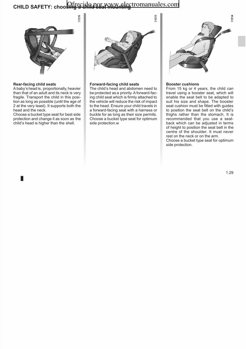
Rear-facing cild eat
A baby’s head is, proportionally, heavier than that of an adult and its neck is veryfragile. Transport the child in this posi-tion as long as possible (until the age of 2 at the very least). It supports both thehead and the neck.Choose a bucket type seat for best sideprotection and change it as soon as thechild’s head is higher than the shell.
Forward-facing cild eat
The child’s head and abdomen need tobe protected as a priority. A forward-fac-ing child seat which is firmly attached tothe vehicle will reduce the risk of impactto the head. Ensure your child travels ina forward-facing seat with a harness or buckle for as long as their size permits.Choose a bucket type seat for optimumside protection.w
Booter cuion
From 15 kg or 4 years, the child cantravel using a booster seat, which willenable the seat belt to be adapted tosuit his size and shape. The booster seat cushion must be fitted with guidesto position the seat belt on the child’sthighs rather than the stomach. It isrecommended that you use a seat-back which can be adjusted in termsof height to position the seat belt in the
centre of the shoulder. It must never rest on the neck or on the arm.Choose a bucket type seat for optimumside protection.
ChILD sAFETY: cooing a cild eat mounting (1/3)
Cooing te attacment Attacment uing te ISOFIX
Ofrecido por www.electromanuales.com

8/6/2019 NU773-8_ENG
http://slidepdf.com/reader/full/nu773-8eng 36/223
1.30
Cooing te attacment
There are two ways of attaching childseats: via the seat belt or using theISOFIX system.
Attacment via te eat belt
The seat belt must be adjusted toensure that it is effective in the event of harsh braking or an impact.
Ensure that the strap paths indicatedby the child seat manufacturer are re-spected.
Always check that the seat belt is cor-rectly fastened by pulling it up, thenpulling it out fully whilst pressing on thechild seat.
Check that the seat is correctly held bymoving it from side to side and backto front: the seat should remain firmlyfixed.
Check that the child seat has not beeninstalled at an angle and that it is notresting against a window.
Attacment uing te ISOFIX ytem
Authorised ISOFIX child seats are ap-proved in accordance with regulationECE-R44 in one of the three followingcases: – ISOFIX universal 3-point forward-
facing seat – ISOFIX semi-universal 2-point seat – specific
For the latter two, check that your childseat can be installed by consulting thelist of compatible vehicles.
Attach the child seat with the ISOFIXlocks, if these are provided. The ISOFIXsystem allows quick, easy, safe fitting.
The ISOFIX system consists of 2 ringsand, in some cases, a third ring.
Before using an ISOFIXchild seat that you pur-
chased for another vehicle,check that its installation isauthorised. Consult the list of ve-hicles which can be fitted with theseat from the equipment manufac-turer.
The seat belt must never be twisted or the tensionrelieved. Never pass theshoulder strap under the
arm or behind the back.Check that the seat belt has notbeen damaged by sharp edges.If the seat belt does not operate nor-mally, it will not protect the child.Consult an approved dealer. Do notuse this seat until the seat belt hasbeen repaired.
Do not use the child seatif it may unfasten the seatbelt restraining it: the baseof the seat must not rest on
the buckle and/or catch of the seatbelt.
No modifications may bemade to the componentparts of the restraint system(seat belts, ISOFIX, seats
and their mountings) originally fitted.
ChILD sAFETY: cooing a cild eat mounting (2/3)Ofrecido por www.electromanuales.com

8/6/2019 NU773-8_ENG
http://slidepdf.com/reader/full/nu773-8eng 37/223
1.31
The two rings 1 are located between
the seatback and the seat base of theseat or bench seat and are identified bya marking.
To ensure your child seat can be easilyfitted and locked on rings 1, use accessguides 2 on the child seat.
The ISOFIX anchoragepoints have been exclu-sively designed for childseats with the ISOFIX
system. Never fit a different type of child seat, seat belt or other objectsto these anchorage points.
Check that nothing is obstructingthe anchorage points.
If your vehicle has been involved ina road accident, have the ISOFIXanchorage points checked and re-place your child seat.
1
2
ChILD sAFETY: cooing a cild eat mounting (3/3)Ofrecido por www.electromanuales.com

8/6/2019 NU773-8_ENG
http://slidepdf.com/reader/full/nu773-8eng 38/223
1.32
The third ring is used to attach the
upper strap on some child seats.Fit the hook of the strap onto ring 3 (for the rear seats) or 4 (for the front seats)and pull the strap.
Do not change the position of the seatto which the child/baby seat is fittedafter pulling the strap.
RIsK OF DEATh ORsERIOUs INJURY: beforeinstalling a child seat in thefront passenger seat, make
sure the air bag has been deacti-vated (refer to the information on“Child safety: deactivating/activat-ing the front passenger air bag” in
Section 1).Forward facing harness seats areonly permitted if they are installedusing an ISOFIX fitting and withouta seat belt.
34
ChILD sAFETY: fitting a cild eat (1/7)
Some seats are not suitable for fitting In te front eat In te rear ide eat
Ofrecido por www.electromanuales.com

8/6/2019 NU773-8_ENG
http://slidepdf.com/reader/full/nu773-8eng 39/223
1.33
gchild seats. The diagram on the follow-ing page shows you how to attach achild seat.
The types of child seat indicated maynot be available. Before using a differ-ent child seat, check with the manufac-
turer that it can be fitted.
The laws concerning children travel-ling in this seat differ in every coun-try. Consult the legislation in force andfollow the indications on the diagram onthe following page.Before fitting a child seat in this seat (if
authorised): – lower the seat belt as far as possible; – move the seat as far back as possi-
ble; – gently tilt the seatback away from
vertical (approximately 25°).Do not change these settings after thechild seat is installed.
A carrycot can be installed across thevehicle and will take up at least twoseats. Position the child with his or her feet nearest the door.
Before installing a child seat, it is rec-ommended that the rear seat be as far back as possible, ensuring, if required,that the floor support of the child seat isresting on the floor in accordance withthe child seat instructions.
Move the front seat as far forward aspossible to install a child seat, thenmove back the seat or seats in front inaccordance with the child seat instruc-tions.
For the safety of the child in the for-ward-facing seat, do not move the seatin front back past the middle of therunner, do not tilt the seatback too far (maximum of 25°) and move the seatbackwards as far as possible.
Check that the forward-facing child seatis resting against the back of the vehi-cle seat and that the headrest of the ve-
hicle is not obstructing its use.
Fit the child seat in a rear seat wherever possible.
Check that when installing
the child seat in the vehicleit is not at risk of coming loose fromits base.
If you have to remove the headrest,check that it is correctly stored sothat it does not come loose under harsh braking or impact.
Always attach the child seat to thevehicle even if it is not in use so that
it does not come loose under harshbraking or impact.
RIsK OF DEATh OR
sERIOUs INJURY: beforeinstalling a child seat in thefront passenger seat, make
sure the air bag has been deacti-vated (refer to the information on“Child safety: deactivating/activat-ing the front passenger air bag” insection 1).
Forward facing harness seats are
only permitted if they are installedusing an ISOFIX fitting and withouta seat belt.

8/6/2019 NU773-8_ENG
http://slidepdf.com/reader/full/nu773-8eng 40/223
ChILD sAFETY: fitting a cild eat (3/7)
³Benc eat verion
Ofrecido por www.electromanuales.com

8/6/2019 NU773-8_ENG
http://slidepdf.com/reader/full/nu773-8eng 41/223
1.35
³ Check the status of the air bagbefore fitting a child seat or allowing apassenger to use the seat.
Cild eat attaced uing te IsOFIXmounting
ü Seat which allows an ISOFIXchild seat to be fitted.
± The rear seats are fitted withan anchorage point which allows aforward-facing ISOFIX child seat withUniversal approval to be fitted. The an-chorage points are located in the lug-gage compartment and are visible.
The size of the ISOFIX child seat is in-dicated by a letter: – A, B and B1: for forward-facing seats
in group 1 (9 to 18 kg); – C: rear-facing seats in group 1 (9 to
18 kg); – D and E: shell seat or rear-facing
seats in group 0 or 0+ (less than13 kg);
– F and G: cots in group 0 (less than
10 kg).
Using a child safety system which is not approved for this vehicle will notcorrectly protect the baby or child. They risk serious or even fatal injury.
RIsK OF DEATh ORsERIOUs INJURY: beforeinstalling a rear-facing childseat in the front passen-
ger seat, make sure the air bag hasbeen deactivated (refer to Section1 “Child safety: front passenger air bag deactivation/activation”).
Forward facing harness seats areonly permitted if they are installedusing an ISOFIX fitting and withouta seat belt.
Cild eat attaced uing te belt
¬ Seat which allows a child seatwith “Universal” approval to be attachedby a seat belt.
− Seat which only allows a rear-facing eat with “Universal” approvalto be attached with a seat belt.
ChILD sAFETY: fitting a cild eat (4/7)
Te table below ummarie te information already own on te diagram on te reviou age, to enure te regula-ti i f t d
Ofrecido por www.electromanuales.com

8/6/2019 NU773-8_ENG
http://slidepdf.com/reader/full/nu773-8eng 42/223
1.36
Tye of cild eat
(verion witearate eat)
Weigt of te cild
seat ize IsOFIXpaenger front
eat (1) (2)Rear ide eat (3)
Carrycot fitted acro teveicleGroup 0
< 10 kg F, G X U - IL (4)
sell eat/rear-facing eatGroup 0, 0+ and 1
< 13 kg and9 to 18 kg
C, D, E U - IL U - IL (5)
Forward-facing eatGroup 1
9 to 18 kg A, B, B1 IL - IUF U - IUF - IL (6)
Booter eatGroup 2 and 3
15 to 25 kg and22 to 36 kg
– X U (6)
tion in force are reected.
(1) RIsK OF DEATh OR sERIOUs INJURY: before installing a rear-facing child seat on the front passenger seat,check that the air bag has been deactivated (refer to Section 1 “Child safety: deactivating/activating the front passen-ger air bag”).
Forward facing harness seats are only permitted if they are installed using an ISOFIX fitting and without a seat belt.
ChILD sAFETY: fitting a cild eat (5/7)
X = Seat not suitable for fitting child seats.
Ofrecido por www.electromanuales.com

8/6/2019 NU773-8_ENG
http://slidepdf.com/reader/full/nu773-8eng 43/223
1.37
U = Seat which allows a child seat with “Universal” approval to be attached by seat belt; check that it can be fitted.
IUF/IL = On equipped vehicles, seat which allows a child seat with “universal/semi-universal or vehicle specific” approval to be at-tached using the ISOFIX device; check that it can be fitted correctly.
(2) Before fitting a rear-facing child/baby seat: raise the seat to the maximum and position it as far back as possible, tilting theseatback slightly (approximately 25°).
(3) It is recommended to position the rear seat as far back as possible ensuring, if required, that the floor support of the child/babyseat is resting on the floor in accordance with the child/baby seat instructions.
(4) A carrycot can be installed across the vehicle and will take up two seats. Position the child with his or her feet nearest the door.
(5) Move the front seat as far forward as possible to install a rear-facing child seat, then move back the seat or seats in front inaccordance with the child seat instructions.
(6) Forward-facing child seat; position the seatback of the child seat in contact with the seatback of the vehicle seat. Adjust theheight of the headrest or remove it if necessary; do not push the seat in front of the child more than halfway back on its runnersand do not recline the seatback more than 25°.
ChILD sAFETY: fitting a cild eat (6/7)
Te table below ummarie te information already own on te diagram on te reviou age, to enure te regula-tion in force are reected
Ofrecido por www.electromanuales.com

8/6/2019 NU773-8_ENG
http://slidepdf.com/reader/full/nu773-8eng 44/223
1.38
Tye of cild eat(benc eat verion)
Weigt of te cild
seat ize IsOFIX
paenger fronteat (1) (2)
Rear ide eat
rigt left
Carrycot fitted acro te veicleGroup 0
< 10 kg F, G X U - IL (4) U (4)
sell eat/rear-facing eatGroups 0, 0 + or 1
< 13 kg and9 kg to 18 kg
D, E U - IL U - IL (5) U (5)
Rear-facing eatGroups 0 + and 1
< 13 kg and9 kg to 18 kg
C U - IL U (3) U (3)
Forward-facing eatGroup 1
9 kg to 18 kg A, B, B1 IL - IUF U - IUF - IL (6) U (6)
Booter cuionGroup 2 or 3
15 kg to 36 kg – X U (6) U (6)
(1) RIsK OF DEATh OR sERIOUs INJURY: before installing a rear-facing child seat on the front passenger seat,check that the air bag has been deactivated (refer to Section 1 “Child safety: deactivating/activating the front passen-ger air bag”).
Forward facing harness seats are only permitted if they are installed using an ISOFIX fitting and without a seat belt.
tion in force are reected.
ChILD sAFETY: fitting a cild eat (7/7)
X = Seat not suitable for fitting child seats.
U S hi h ll hild i h “U i l” l b h d b b l h k h i b fi d
Ofrecido por www.electromanuales.com

8/6/2019 NU773-8_ENG
http://slidepdf.com/reader/full/nu773-8eng 45/223
1.39
U = Seat which allows a child seat with “Universal” approval to be attached by seat belt; check that it can be fitted.
IUF/IL = On equipped vehicles, seat which allows a child seat with “universal/semi-universal or vehicle specific” approval to befitted using the ISOFIX system; check that it can be fitted correctly.
(2) Before fitting a rear-facing child/baby seat: raise the seat to the maximum and position it as far back as possible, tilting theseatback slightly (approximately 25°).
(3) It is recommended to position the rear seat as far back as possible ensuring, if required, that the floor support of the child/babyseat is resting on the floor in accordance with the child/baby seat instructions.
(4) A carrycot can be installed across the vehicle and will take up two seats. Position the child with his or her feet nearest the door.
(5) Move the front seat as far forward as possible to install a rear-facing child seat, then move back the seat or seats in front inaccordance with the child seat instructions.
(6) Forward-facing child seat; position the seatback of the child seat in contact with the seatback of the vehicle seat. Adjust theheight of the headrest or remove it if necessary; do not push the seat in front of the child more than halfway back on its runnersand do not recline the seatback more than 25°.
ChILD sAFETY: deactivating/activating te front aenger air bag (1/2)Ofrecido por www.electromanuales.com
8/6/2019 NU773-8_ENG
http://slidepdf.com/reader/full/nu773-8eng 46/223
1.40
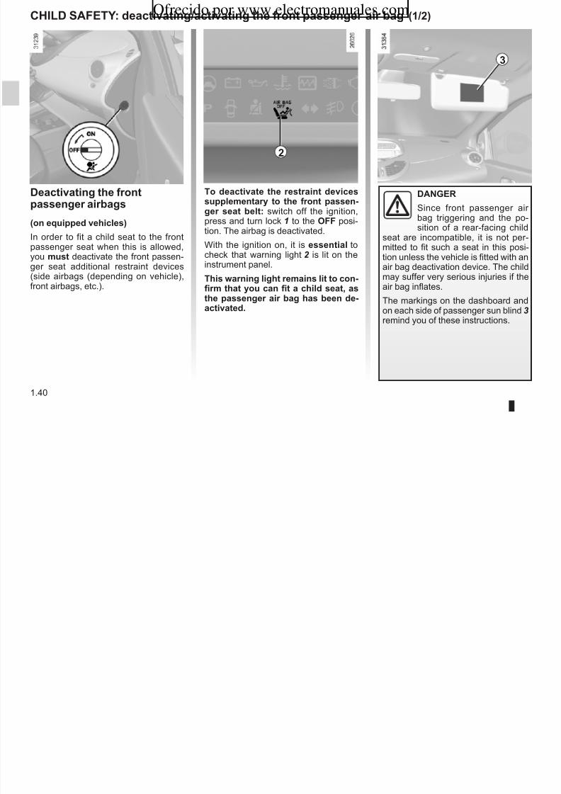
Deactivating te front
aenger airbag(on equied veicle)
In order to fit a child seat to the frontpassenger seat when this is allowed,you mut deactivate the front passen-ger seat additional restraint devices(side airbags (depending on vehicle),front airbags, etc.).
To deactivate te retraint deviceulementary to te front aen-ger eat belt: switch off the ignition,press and turn lock 1 to the OFF posi-tion. The airbag is deactivated.
With the ignition on, it is eential tocheck that warning light 2 is lit on theinstrument panel.
Ti warning ligt remain lit to con-firm tat you can fit a cild eat, ate aenger air bag a been de-activated.
DANGER
Since front passenger air bag triggering and the po-sition of a rear-facing child
seat are incompatible, it is not per-mitted to fit such a seat in this posi-tion unless the vehicle is fitted with anair bag deactivation device. The childmay suffer very serious injuries if theair bag inflates.
The markings on the dashboard andon each side of passenger sun blind 3 remind you of these instructions.
1
2
3
ChILD sAFETY: deactivating/activating te front aenger air bag (2/2)Ofrecido por www.electromanuales.com
8/6/2019 NU773-8_ENG
http://slidepdf.com/reader/full/nu773-8eng 47/223
1.41
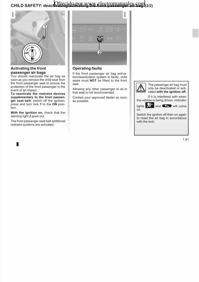
Activating te front
aenger air bagYou should reactivate the air bag assoon as you remove the child seat fromthe front passenger seat to ensure theprotection of the front passenger in theevent of an impact.To reactivate te retraint deviceulementary to te front aen-ger eat belt: switch off the ignition,press and turn lock 1 to the ON posi-
tion.Wit te ignition on, check that thewarning light 2 goes out.
The front passenger seat belt additionalrestraint systems are activated.
Oerating fault
If the front passenger air bag activa-tion/deactivation system is faulty, childseats must NOT be fitted to the frontseat.
Allowing any other passenger to sit inthat seat is not recommended.
Contact your approved dealer as soonas possible.
The passenger air bag mustonly be deactivated or acti-vated wit te ignition off .
If it is interfered with whenthe vehicle is being driven, indicator
lightså and© will comeon.
Switch the ignition off then on againto reset the air bag in accordancewith the lock.
1
2
DRIVING pOsITION, LEFT-hAND DRIVE (1/2)
321 4 5 6 7 8 9 10 11 12 13 14 15
Ofrecido por www.electromanuales.com

8/6/2019 NU773-8_ENG
http://slidepdf.com/reader/full/nu773-8eng 48/223
1.42
29 28 27 26 25 24 19 18 17 16
23
22
21
20
DRIVING pOsITION, LEFT-hAND DRIVE (2/2)
Te equiment fitted, decribed below, DEpENDs ON ThE VERsION AND COUNTRY.
Ofrecido por www.electromanuales.com

8/6/2019 NU773-8_ENG
http://slidepdf.com/reader/full/nu773-8eng 49/223
1.43
1 Side window demister outlet.
2 Side air vent.
3 Stalk:
– direction indicator lights; – exterior lights; – front fog lights; – rear fog lights; – horn.
4 Driver’s air bag location, cruisecontrol/speed limiter controls.
5 Rev counter.
6 Storage compartments.
7 Radio remote control.
8 – Windscreen and rear screenwiper/washer stalk;
– Instrument panel information re-adout control.
9 Centre air vents.
10 Instrument panel.
11 Display: – clock and temperature; – radio, clock and temperature or
storage compartment.
12 Windscreen demister outlet.
13 Passenger air bag location.
14 Side window demister.
15 Side air vent.
16 Glove box.
17 Hazard warning light switch andcentral door locking switch.
18 Heating and ventilation controls.
19 Location for radio or storage com-partment.
20 Accessories socket or cigar lighter and ashtray.
21 Handbrake.
22 Gear lever.
23 Cup holder.
24 Parking distance control switch.
25 Ignition switch.
26 Steering wheel height adjustmentcontrol.
27 Fuse box.
28 Controls for: – electric beam height adjust-
ment; – lighting dimmer for control in-
struments; – cruise control and speed limiter.
29 Bonnet release.
DRIVER’s pOsITION, RIGhT-hAND DRIVE
2 3 4 5 6 7 8 9 10 11 12 13 141
Ofrecido por www.electromanuales.com

8/6/2019 NU773-8_ENG
http://slidepdf.com/reader/full/nu773-8eng 50/223
1.44
151617181920
2122
23
24
2728 2526
DRIVER’s pOsITION, RIGhT-hAND DRIVE (continued)
Te equiment fitted, decribed below, DEpENDs ON ThE VERsION AND COUNTRY.
Ofrecido por www.electromanuales.com

8/6/2019 NU773-8_ENG
http://slidepdf.com/reader/full/nu773-8eng 51/223
1.45
1 Side window demister outlet.
2 Side air vent.
3 Location for passenger air bag.
4 Windscreen demister outlet.
5 Centre air vents.
6 Instrument panel.
7 Display: – clock and temperature; – radio, clock and temperature or
storage compartment.
8 – Windscreen and rear screenwiper/washer stalk;
– Instrument panel information re-adout control.
9 Storage compartment.
10 Driver’s air bag location, cruise
control/speed limiter controls.
11 Rev counter.
12 Stalk for: – direction indicator lights; – exterior lights;
– front fog lights; – rear fog lights; – horn.
13 Side window demister outlet.
14 Side air vent.
15 Radio remote control.
16 Ignition switch.
17 Controls for: – electric beam height adjust-
ment; – lighting dimmer for control in-
struments; – cruise control and speed limiter.
18 Steering wheel height adjustment
control.
19 Parking distance control switch.
20 Heating and ventilation controls.
21 Accessories socket or cigar lighter
and ashtray.
22 Handbrake.
23 Gear lever.
24 Cup holder.
25 Location for radio or storage com-partment.
26 Hazard warning light switch andcentral door locking switch.
27 Glove box and fuse box.
28 Bonnet release.
INsTRUMENT pANEL: warning ligt (1/4)
Te reence and oeration of te warning and indicator ligt decribed below DEpEND ON ThE EQUIpMENT AND ThECOUNTRY.
Ofrecido por www.electromanuales.com

8/6/2019 NU773-8_ENG
http://slidepdf.com/reader/full/nu773-8eng 52/223
1.46
D handbrake on and brake cir-cuit incident warning ligt
If it comes on during braking and is ac-
companied by theû warning light
and a beep, it indicates that the fluidlevel in the circuit is low or that there isa braking system fault.
Stop as soon as traffic conditions allowand contact an approved dealer.
U Variable ower-aitedteering warning ligt
This comes on when the ignition isswitched on and goes out after a few
seconds. If this warning light remainson, it indicates a system fault. Stopas soon as traffic conditions allow andcontact an approved dealer.
If no lights or sounds are ap-parent, this indicates a faultin the instrument panel. Thisindicates that it is essential
to stop immediately (as soon as traf-fic conditions allow). Ensure that thevehicle is correctly immobilised andcontact an approved Dealer.
The© warning light meansyou should drive very carefully toan approved dealer as soon as pos-sible. If you fail to follow this recom-mendation, you risk damaging your vehicle.
Warning light® re-quires you to stop immedi-
ately, for your own safety,as soon as traffic conditions allow.Switch off the engine and do not re-start it. Contact an approved Dealer.
Intrument anel A
A
INsTRUMENT pANEL: warning ligt (2/4)
Te reence and oeration of te warning and indicator ligt decribed below DEpEND ON ThE EQUIpMENT AND ThECOUNTRY.
Ofrecido por www.electromanuales.com

8/6/2019 NU773-8_ENG
http://slidepdf.com/reader/full/nu773-8eng 53/223
1.47
Ü particle filter
Refer to the information on“Special features of diesel versions” inSection 2.
Ä Toxic Fume Filter sytemWarning Ligt
For vehicles equipped with this option,the light comes on when the ignition isswitched on then goes out.
If it comes on continuously, consult your approved dealer as soon as possible.
If it flashes, reduce the engine speeduntil the light stops flashing.
Contact your approved dealer as soonas possible.
Refer to the information on“Antipollution, fuel economy and driv-ing” in Section 2.
Ú Battery carge warning ligt
This lights up when the ignitionis switched on and goes out after a fewseconds. If it comes on together with
theû warning light and a beep,it indicates that the electrical circuit isovercharged or undercharged.
If it flashes on its own, this indicatesthat the battery is low. Stop as soon astraffic conditions allow and contact anapproved dealer.
À Oil reure warning ligt
This lights up when the ignition isswitched on and goes out after a fewseconds.
If it comes on when the vehicle is being
driven, accompanied by theû warning light and a beep, it is essentialto stop and switch off the ignition.
Check the oil level. If the level is normal,the indicator light is being lit by some-thing else.
Contact an approved dealer.Ô Coolant temerature warn-
ing ligt
If it shows a steady light, stop and letthe engine idle for a minute or two. Thetemperature should lower and the warn-ing light should go out. Let the enginecool down before checking the coolant.
Contact an approved dealer.
INsTRUMENT pANEL: warning ligt (3/4)
Te reence and oeration of te warning and indicator ligt decribed below DEpEND ON ThE EQUIpMENT AND ThECOUNTRY.
Ofrecido por www.electromanuales.com

8/6/2019 NU773-8_ENG
http://slidepdf.com/reader/full/nu773-8eng 54/223
1.48
2Not ued
ç seat belt reminder ligt
If the driver’s seat belt is notfastened the light remains lit when thevehicle is started, then when the car reaches a speed of approximately 6mph (10 km/h), it flashes and a beepsounds for approximately 2 minutes.
ã paenger air bag warningligt OFF
It lights up when the ignition is switched
on and goes out after a few seconds,unless the passenger air bag is deacti-vated (refer to Section 1: “Deactivatingthe front passenger air bags”).
å Air bag warning ligt
This lights up when the ignitionis switched on and goes out after a fewseconds.
If it remains lit or comes on when theengine is running, it indicates a systemfault.
Contact your approved dealer as soonas possible.
x Anti-lock braking warningligt
This lights up when the ignition isswitched on and goes out after a fewseconds.
If it does not go out when the ignition isswitched on, or lights up when driving,there is a fault with the ABS.
Braking will then be as normal, withoutthe ABS.
Contact an approved dealer as soon aspossible.
ûsTOp ligt
It switches off a few secondsafter the ignition is switched on, if itdoes not light up, consult an approveddealer. It may light up at the same timeas other warning lights, together witha beep. It indicates that it is essentialto stop immediately (as soon as trafficconditions allow). Contact an approveddealer.
INsTRUMENT pANEL: warning ligt (4/4)
Te reence and oeration of te warning and indicator ligt decribed below DEpEND ON ThE EQUIpMENT AND ThECOUNTRY.
Ofrecido por www.electromanuales.com

8/6/2019 NU773-8_ENG
http://slidepdf.com/reader/full/nu773-8eng 55/223
1.49
u side ligt tell-tale ligt
k Died beam eadligt tell-tale ligt
á Main beam eadligt tell-taleligt
Ò sequential gearbox elec-tronic fault warning ligt or
water in te dieel warning ligt
This light flashes when the ignition isswitched on (without engine running).It is then continuously lit for a few sec-onds before going out again.
If it comes on when driving, it indicatesa fault in the injection computer or thesequential gearbox, or the presence of water in the diesel.
Contact your approved dealer as soonas possible.
d Direction indicator tell-taleligt
g Front fog ligt tell-tale ligt
f Rear fog ligt telltale ligt
©Warning ligt
This lights up when the igni-tion is switched on and goes out after afew seconds. It may come on with other warning lights on the instrument panel.
If it lights up when the vehicle is beingdriven, it is advisable to stop at an ap-proved dealer soon.
Î seed limiter and cruiecontrol warning ligt
To understand how this operates, refer to the information on “Cruise control”and “Speed limiter” in Section 2.
É preeating warning ligt(diesel version)
With the ignition on, this light comes on;it indicates that the heater plugs are op-erating. It goes out as soon as preheat-ing is sufficient and the engine may bestarted.
INsTRUMENT pANEL: dilay and indicator
12 3 5
Ofrecido por www.electromanuales.com

8/6/2019 NU773-8_ENG
http://slidepdf.com/reader/full/nu773-8eng 56/223
1.50
Rev counter 1 (graduation x100)(deending on veicle)
seedometer 2
To change from miles to km/h, refer tothe information on the “Trip computer and warning system” in Section 1.
Overeed buzzer
Depending on the vehicle, a buzzer sounds for approximately 10 seconds
every 30 seconds, as long as the ve-hicle is travelling in excess of 72 mph(120 km/h).
sequential gearbox dilay 3This indicates the gear engaged (de-
pending on the vehicle). Refer to the in-formation on the “Quickshift gearbox” inSection 2.
Fuel gauge 4
Low fuel level warning ligtIf it flashes and a beep sounds, this in-dicates that the minimum fuel level hasbeen reached. Fill up with fuel as soon
as soon as possible.Each time the ignition is switched onwhen the minimum fuel level has beenreached, a beep sounds to warn you.
Information dilay 5
Depending on the vehicle, it includes: – the time; – the exterior temperature; – radio information.
1
4
TRIp COMpUTER AND WARNING sYsTEM (1/3)
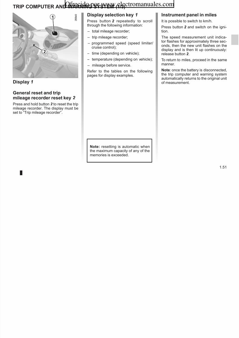
Dilay election key 1
Press button 2 repeatedly to scrollth h th f ll i i f ti
Intrument anel in mile
It is possible to switch to km/h.1
Ofrecido por www.electromanuales.com
8/6/2019 NU773-8_ENG
http://slidepdf.com/reader/full/nu773-8eng 57/223
1.51
Dilay 1
General reet and trimileage recorder reet key 2
Press and hold button 2 to reset the tripmileage recorder. The display must beset to “Trip mileage recorder”.
through the following information:
– total mileage recorder;
– trip mileage recorder;
– programmed speed (speed limiter/
cruise control); – time (depending on vehicle);
– temperature (depending on vehicle);
– mileage before service.
Refer to the tables on the followingpages for display examples.
Note: resetting is automatic whenthe maximum capacity of any of thememories is exceeded.
Press button 2 and switch on the igni-tion.
The speed measurement unit indica-tor flashes for approximately three sec-
onds, then the new unit flashes on thedisplay and is then lit up continuously:release button 2 .
To return to miles, proceed in the samemanner.
Note: once the battery is disconnected,the trip computer and warning systemautomatically returns to the original unitof measurement.
2

8/6/2019 NU773-8_ENG
http://slidepdf.com/reader/full/nu773-8eng 58/223
TRIp COMpUTER AND WARNING sYsTEM (3/3)
Te dilay of information own below DEpENDs ON ThE VEhICLE EQUIpMENT AND COUNTRY.
Ofrecido por www.electromanuales.com

8/6/2019 NU773-8_ENG
http://slidepdf.com/reader/full/nu773-8eng 59/223
1.53
Examle of dilay electionby reeatedly reing button 2
Interreting te dilay elected
service ditanceDistance remaining until the next service.
There are several scenarios: – distance less than 900 mile (1,500 km). It appears on the display for approxi-
mately 8 seconds when the ignition is switched on as soon as the distance isless than or equal to 900 mile (1,500 km).
– distance less than 0 mile/km. The© indicator light will light up on theinstrument panel.
Te veicle require a ervice a oon a oible.
Note: depending on the vehicle, the mileage before service changes according to the driving style (frequent driving at low speed,door-to-door journeys, extensive use at idle speed, towing a trailer etc.). The distance remaining until the next service can there-fore decrease more quickly in some cases than the actual distance travelled.
Reetting te dilay after te ervice in accordance wit te maintenance cedule.The mileage before service must only be reset after a service which complies with the recommendations in the maintenanceschedule.
If you decide to change the oil more frequently, do not reset this data each time the oil is changed to avoid exceeding the replace-
ment intervals for other parts in the maintenance schedule.secial note: To reset the distance before service, press and hold one of the display reset buttons for approximately 10 secondsuntil the display shows the mileage permanently.
sTEERING WhEEL Ofrecido por www.electromanuales.com
8/6/2019 NU773-8_ENG
http://slidepdf.com/reader/full/nu773-8eng 60/223
1.54
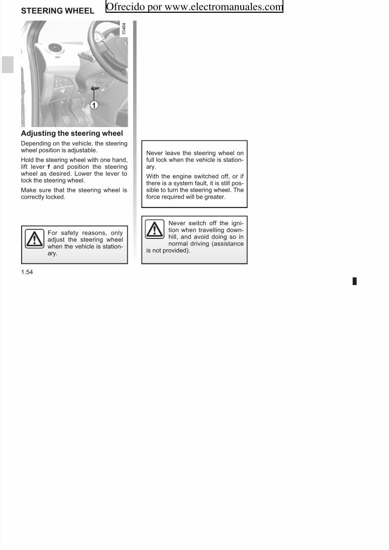
Adjuting te teering weel
Depending on the vehicle, the steeringwheel position is adjustable.
Hold the steering wheel with one hand,lift lever 1 and position the steeringwheel as desired. Lower the lever tolock the steering wheel.
Make sure that the steering wheel iscorrectly locked.
For safety reasons, onlyadjust the steering wheelwhen the vehicle is station-ary.
Never leave the steering wheel onfull lock when the vehicle is station-ary.
With the engine switched off, or if there is a system fault, it is still pos-sible to turn the steering wheel. Theforce required will be greater.
Never switch off the igni-tion when travelling down-hill, and avoid doing so innormal driving (assistance
is not provided).
1
CLOCK AND EXTERIOR TEMpERATURE
Reetting te clock
Vehicle with button 1:– Press button1 for approximately
Ofrecido por www.electromanuales.com

8/6/2019 NU773-8_ENG
http://slidepdf.com/reader/full/nu773-8eng 61/223
1.55
Dilay A
Wit te ignition on, the time and,depending on the vehicle, the exterior temperature are displayed.
External temerature in-dicator
As ice formation is relatedto exposure, local air hu-
midity and temperature, the external
temperature alone is not sufficient todetect ice.If the electrical supply is cut (batterydisconnected, broken supply wire,etc.), the clock will lose its time set-ting.
The clock must be reset.
Press button1 for approximatelythree seconds;
– when the hour flashes, pressbutton 1 again to adjust it;
– wait approximately three seconds,
the minutes will flash, press button 1 to adjust them; – wait approximately three seconds,
the minutes stop flashing, the time isset.
1
A
For your safety, we recom-mend that you do not adjustthe clock while driving.
Reetting te clock
Wit te ignition on, press button: H for the hours;
TIME AND EXTERIOR TEMpERATURE (continued)
External temeratureindicator
s i l t
Ofrecido por www.electromanuales.com

8/6/2019 NU773-8_ENG
http://slidepdf.com/reader/full/nu773-8eng 62/223
1.56
; M for the minutes.
Note: for vehicles which are not fittedwith buttons H and M , refer to the spe-cific equipment instructions to discover
the special features.
Dilay B(depending on vehicle)
Wit te ignition on, the time and,depending on the vehicle, the exterior temperature are displayed.
secial note:
When the external temperature is be-tween –3°C and +3°C, the °C figuresflash (indicates risk of ice formation).
If the electrical supply is cut (batterydisconnected, broken supply wire,etc.), the clock will lose its time set-ting.
The clock must be reset.
External temerature in-dicator
As ice formation is relatedto exposure, local air hu-
midity and temperature, the external
temperature alone is not sufficient todetect ice.
h
M
B
For your safety, we recom-mend that you do not adjustthe clock while driving.
REAR VIEW MIRRORsOfrecido por www.electromanuales.com

8/6/2019 NU773-8_ENG
http://slidepdf.com/reader/full/nu773-8eng 63/223
1.57
heated door mirror(depending on vehicle)
The door mirrors are de-iced when therear screen demisting/de-icing is active.
Door mirror wit manualadjutment
To adjust the mirror, move lever 2 .
Door mirror wit electricaladjutment:
Wit te ignition on, position control 1 on:
A to adjust the left-hand door mirror,C to adjust the right-hand door mirror,B to deactivate it.
The door mirror on the driver’s side has two clearly defined zones. Zone E shows what can normally be seen in anordinary rear view mirror. For your safety, zone D increases the rear side visibility.
Object in zone D look muc furter away tan tey really are.
Interior rear view mirror
Its position can be adjusted. When driv-ing at night, to avoid being dazzled bythe headlights of the vehicle behind,depress the little lever located behindthe rear view mirror 3.
For safety reasons, carryout any adjustments whenthe vehicle is not beingdriven.
1A B
C
D E2
3
EXTERIOR LIGhTING AND sIGNALs (1/4)
1 2
Ofrecido por www.electromanuales.com

8/6/2019 NU773-8_ENG
http://slidepdf.com/reader/full/nu773-8eng 64/223
1.58
uswitcing on te ideligt
Turn the end of stalk 1 until the symbolis opposite mark 2 .
The instrument panel lights up, thebrightness can be adjusted by rotatingcontrol 3.
Adjuting te brigtne of te intrument anel ligting
Turn control 3 downwards to reduce thebrightness and upwards to increase it. Before driving at night,
check that the electricalequipment is operating cor-rectly and adjust the head-
light beams (if your vehicle is notcarrying its normal load). As a gen-eral precaution, check that the lightsare not obscured (by dirt, mud, snowor objects which could cover them).
1
3
EXTERIOR LIGhTING AND sIGNALs (2/4)
Automatic oeration
With the engine running on vehiclesfitted with a ligt enor , the dippedb h dli ht t ti
see-me-ome ligting feature (de-pending on vehicle)
This function (useful, for example, for i t t ) bl
1 2
Ofrecido por www.electromanuales.com

8/6/2019 NU773-8_ENG
http://slidepdf.com/reader/full/nu773-8eng 65/223
1.59
kDied beameadligt
Manual oeration
Turn the end of stalk 1 until the symbolis opposite mark 2 .
An indicator light on the instrumentpanel will come on.
beam headlights come on automati-cally as light begins to fade; the stalkdoes not need to be turned (position 0).
To deactivate or reactivate this function,
move the end of stalk 1 twice consecu-tively from 0 to side light position, withthe vehicle stopped and the ignition on.
A bleep confirms the deactivation of thisfunction, and two bleeps confirm its re-activation.
opening a gate, garage, etc.) enablesyou to switch the dipped headlights onmomentarily.
With the ignition off and the headlights
off, pull stalk 1 towards you: the dippedbeam headlights come on for approxi-mately thirty seconds.
This action may be carried out no morethan four times for a maximum lightingperiod of two minutes.
To switch off the lights before theygo out automatically, turn the end of stalk 1, then return it to position 0.
Before driving at night, check that the electrical equipment is in good condition and adjust the headlight beams (if your vehicle is not carrying its normal load). As a general precaution, check that the lights are not obscured (by dirt, mud,snow or objects which could cover them).
EXTERIOR LIGhTING AND sIGNALs (3/4)
Ligt-on warning buzzer
A warning buzzer will sound when thedriver’s door is opened and the lights
l ft ft th i iti h b
1
Ofrecido por www.electromanuales.com

8/6/2019 NU773-8_ENG
http://slidepdf.com/reader/full/nu773-8eng 66/223
1.60
áMain beam eadligt
When the dipped beam head-lights are lit, pull stalk 1 towards you(an indicator light on the instrumentpanel lights up).
To return to the dipped beam headlightposition, pull the stalk towards you.
eswitcing off te ligt
Return the stalk to its original
position.
are left on after the ignition has beenswitched off (to prevent the battery run-ning down, etc.).
Before driving at night,check that the electricalequipment is in good con-dition and adjust the head-
light beams (if your vehicle is notcarrying its normal load). Check that
the lights are not obscured (by dirt,mud, snow or objects which couldcover them).
EXTERIOR LIGhTING AND sIGNALs (4/4)
fRear fog ligt
Turn centre ring 4 on stalk Aor B, depending on vehicle, until thesymbol faces mark 5
switcing off te ligt
– stalk A: return the centre ring 4 to itsinitial position.
B 4 5
Ofrecido por www.electromanuales.com

8/6/2019 NU773-8_ENG
http://slidepdf.com/reader/full/nu773-8eng 67/223
1.61
gFront fog ligt
Turn centre ring 4 on stalk Aor B, depending on vehicle, until thesymbol faces mark 5 .
When you release the stalk, it returns toposition 0 (stalk B) or remains in frontfog lights position (stalk A).
symbol faces mark 5 .
When you release the stalk, it returnsto position 0 (stalk B) or remains in rear fog lights position (stalk A).
Note: the fog light is located on thedriver’s side.
Feature of te front and rear fogligt:
Operation of the fog lights depends onthe exterior lighting selected, and an in-dicator light will light up on the instru-ment panel.
To avoid inconveniencing other roadusers, remember to switch off the rear fog light when it is no longer needed.
– stalkB: turn centre ring 4 untilmark 5 is opposite the symbol for thefog light you wish to turn off.
The front and rear fog lights switch off when the exterior lights are switchedoff.
secial cae
The front and rear fog lights do not op-erate in automatic mode.
They only come on when the end of
ring 4 is in positionu or k.
A 4 5
ELECTRIC BEAM hEIGhT ADJUsTMENT
Examle of oition for adjutingcontrol A according to te load
Ofrecido por www.electromanuales.com

8/6/2019 NU773-8_ENG
http://slidepdf.com/reader/full/nu773-8eng 68/223
1.62
On vehicles fitted with this function,control A allows you to adjust the height
of the beams according to the load.Turn control A downwards to lower theheadlights and upwards to raise them.
All verion excetcommercial veicle
Commercial veicle
Driver only 0 _
Driver alone or wit frontaenger
0 _
Driver wit one frontaenger and two rear
aenger
1 –
Driver wit treeaenger wit luggage
2 –
Driver wit luggage or loadreacing te maximumautoried load weigt
3 3
A
AUDIBLE AND VIsUAL sIGNALsDepending on the vehicle, the hazardwarning lights may come on automati-cally under deliberate heavy decelera-tion.
Ofrecido por www.electromanuales.com

8/6/2019 NU773-8_ENG
http://slidepdf.com/reader/full/nu773-8eng 69/223
1.63
horn
Press the end of the stalk 1.
headligt flaer
Pull stalk 1 towards you to flash theheadlights.
éhazard warning ligt
Press switch 2 .
This switch activates all four directionindicators and the side indicator lightssimultaneously.
Only use this function to warn other road users if:
– you have to stop in an area wherestopping is prohibited or unexpected;
– you are obliged to drive under spe-
cial conditions.
In this case, the hazard warning lightsmay be switched off by pressingswitch 2 once.
Direction indicator
Move stalk 1 parallel to the steeringwheel and in the direction you are goingto turn it.
When driving on the motorway, thesteering wheel is not often turnedenough to return the stalk automaticallyto 0 . There is an intermediate position
in which the stalk may be held whenchanging lanes.
When the stalk is released, it automati-cally returns to 0 .
0
1
2
WINDsCREEN WAsh/WIpE (1/2)
Veicle wit automatic wier function
Wit te engine running, movestalk 1:
2
Ofrecido por www.electromanuales.com

8/6/2019 NU773-8_ENG
http://slidepdf.com/reader/full/nu773-8eng 70/223
1.64
nWindcreen wier
Wit te ignition on, movestalk 1:
A ark;
B intermittent wiing:
The wipers will pause for sev-eral seconds between sweeps.Depending on the vehicle, it is pos-sible to change the time betweensweeps by turning ring 2 ;
C normal wiing eed; D fat wiing eed.
secial note
Wen driving every time the vehi-cle stops, the wipers slow down, e.g.fast wiping speed is reduced to normalwiping speed.
As soon as the vehicle moves off,wiping will return to the speed originallyselected.
Any action on stalk 1 overrides andcancels automatic operation.
stalk 1:
A ark;
B automatic wier function:
When this position is selected, thesystem detects the presence of water on the windscreen and triggerswiping at a suitable wiping speed. Itis possible to change the time be-tween sweeps by turning ring 2 ;
C normal wiing eed;
D fat wiing eed.
With the vehicle stationary, if for any reason the wipers cannot move(e.g. stuck to windscreen by ice),the system will automatically cut off the power supply to the wipers.
1
1
A
BC
D
WINDsCREEN WAsh/WIpE (2/2)
In frosty weather, make sure that
Ofrecido por www.electromanuales.com

8/6/2019 NU773-8_ENG
http://slidepdf.com/reader/full/nu773-8eng 71/223
1.65
Windcreen waer
With the ignition on, pull stalk 1 towardsyou.
A short pull triggers one sweep cycleof the wiper. A longer pull triggers threesweeps followed by a final sweep after several seconds.
y ,the wiper blades are not stuck by ice(risk of motor overheating).
Keep an eye on the condition of the
blades. Replace the wiper blades assoon as they begin to lose efficiency(approximately once a year).
If you switch off the ignition beforeswitching off the windscreen wiper the blades will stop at random onthe windscreen.
Clean your windscreen regularly.
1
Before any action on thewindscreen (washing thevehicle, de-icing, cleaningthe windscreen, etc.) return
stalk 1 to position A (park).
Risk of injury and/or damage.
When working in the enginecompartment, ensure thatthe windscreen wiper stalkis in position A (park).
Risk of injury.
REAR sCREEN WAsh/WIpE
Vheated rear creen
Wit te engine running, press button 2 (the integrated indicator on the button will come on).
3
3
2
Ofrecido por www.electromanuales.com
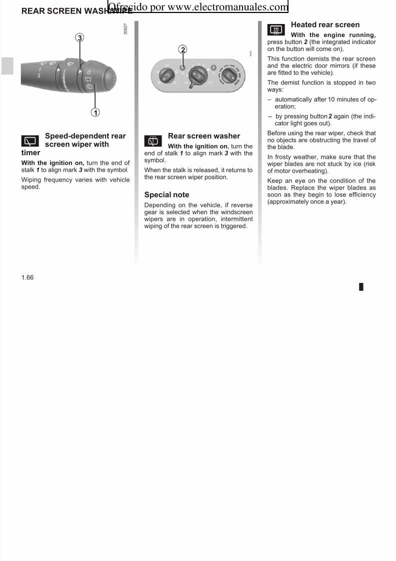
8/6/2019 NU773-8_ENG
http://slidepdf.com/reader/full/nu773-8eng 72/223
1.66
)
This function demists the rear screenand the electric door mirrors (if theseare fitted to the vehicle).
The demist function is stopped in twoways:
– automatically after 10 minutes of op-eration;
– by pressing button2 again (the indi-cator light goes out).
Before using the rear wiper, check thatno objects are obstructing the travel of the blade.
In frosty weather, make sure that thewiper blades are not stuck by ice (riskof motor overheating).
Keep an eye on the condition of theblades. Replace the wiper blades assoon as they begin to lose efficiency(approximately once a year).
Yseed-deendent rear creen wier wit
timer Wit te ignition on, turn the end of stalk 1 to align mark 3 with the symbol.
Wiping frequency varies with vehiclespeed.
pRear creen waer
Wit te ignition on, turn theend of stalk 1 to align mark 3 with thesymbol.
When the stalk is released, it returns tothe rear screen wiper position.
secial note
Depending on the vehicle, if reversegear is selected when the windscreen
wipers are in operation, intermittentwiping of the rear screen is triggered.
1
2
FUEL TANK (1/2)Dieel verion
It is eential to use diesel fuel thatconforms with the information given onthe label inside cover A.
Fuel grade
Ue a ig grade fuel with the appro-priate octane rating as defined by theparticular standards in force in your
Ofrecido por www.electromanuales.com

8/6/2019 NU773-8_ENG
http://slidepdf.com/reader/full/nu773-8eng 73/223
1.67
Make sure that no water accidentallyenters the fuel tank during filling. Thesealing system and its surrounding
area must be dust-free.
ycountry.
petrol verion
It is eential to use unleaded petrol.The octane rating (RON) must conformwith the information given on the labelinside cover A. Refer to the informationon “Engine specifications” in Section 6.
Fuel filler ca: ti i e-cific.
If you have to replace it,make sure it is identical
to the original cap. Contact an ap-proved Dealer.Never place the cap near a sourceof heat or flame.
Do not wash the filler area with ahigh-pressure washer.
After filling, check that the cap andcover are closed.
Do not mix even smallamounts of petrol (un-leaded or E85) with diesel.
Do not use ethanol-basedfuel if your vehicle is not compatiblewith this fuel.
Filling te tank
To open cover A, place your finger intorecess B.
When filling, use the cap holder 1 onthe cover A to secure the cap 2 .
Ueful caacity of te fuel tank: 40litre approximately.
12
A
B
FUEL TANK (2/2)
Filling wit fuel
petrol verion
Using leaded petrol will damage theti ll ti t d l d t
petrol and dieel verion
When the pump cuts out automaticallyat the end of the filling procedure, amaximum of two further filling attempts
b d th t b ffi
Ofrecido por www.electromanuales.com

8/6/2019 NU773-8_ENG
http://slidepdf.com/reader/full/nu773-8eng 74/223
1.68
antipollution system and may lead to aloss of warranty.
To ensure the fuel tank is not filled
with leaded petrol, the fuel tank filler neck contains a restrictor fitted with avalve which only allow te nozzlefor unleaded etrol to be ued (at thepump).
– Insert the nozzle a far a it will go so that the valve is opened.
– Keep the nozzle in this positionthroughout the entire filling opera-tion.
may be made, as there must be suffi-cient space in the fuel tank to allow for expansion.
No modifications what-soever are permitted onany part of the fuel supplysystem (electronic unit,
wiring, fuel circuit, injector, protec-tive covers, etc.) as this may be
dangerous (unless undertaken byqualified Network personnel).
peritent mell of
fuelIf you notice a persistent
smell of fuel you should:
– stop the vehicle as soon as traf-fic conditions allow and switch off the ignition;
– switch on the hazard warninglights and ask your passengersto leave the vehicle and to keep
away from traffic; – contact an approved Dealer.
Section 2: Driving (Advice on use relating to fuel economy and the environment)
Ofrecido por www.electromanuales.com

8/6/2019 NU773-8_ENG
http://slidepdf.com/reader/full/nu773-8eng 75/223
2.1
Running in - Ignition switch . . . . . . . . . . . . . . . . . . . . . . . . . . . . . . . . . . . . . . . . . . . . . . . . . . . . . . . . 2.2Starting/stopping the engine . . . . . . . . . . . . . . . . . . . . . . . . . . . . . . . . . . . . . . . . . . . . . . . . . . . . . . . 2.3Special features of petrol versions . . . . . . . . . . . . . . . . . . . . . . . . . . . . . . . . . . . . . . . . . . . . . . . . . . 2.4Special features of diesel versions . . . . . . . . . . . . . . . . . . . . . . . . . . . . . . . . . . . . . . . . . . . . . . . . . . 2.5Gear lever - Power-assisted steering . . . . . . . . . . . . . . . . . . . . . . . . . . . . . . . . . . . . . . . . . . . . . . . . 2.6Handbrake . . . . . . . . . . . . . . . . . . . . . . . . . . . . . . . . . . . . . . . . . . . . . . . . . . . . . . . . . . . . . . . . . . . . . 2.7
Advice on antipollution and fuel economy . . . . . . . . . . . . . . . . . . . . . . . . . . . . . . . . . . . . . . . . . . . . . 2.8Environment . . . . . . . . . . . . . . . . . . . . . . . . . . . . . . . . . . . . . . . . . . . . . . . . . . . . . . . . . . . . . . . . . . . 2.11Driving correction devices . . . . . . . . . . . . . . . . . . . . . . . . . . . . . . . . . . . . . . . . . . . . . . . . . . . . . . . . . 2.12Cruise control - Speed limiter: limiter function . . . . . . . . . . . . . . . . . . . . . . . . . . . . . . . . . . . . . . . . . . 2.15Cruise control - Speed limiter: cruise control function . . . . . . . . . . . . . . . . . . . . . . . . . . . . . . . . . . . . 2.18Quickshift gearbox . . . . . . . . . . . . . . . . . . . . . . . . . . . . . . . . . . . . . . . . . . . . . . . . . . . . . . . . . . . . . . . 2.22Parking distance control . . . . . . . . . . . . . . . . . . . . . . . . . . . . . . . . . . . . . . . . . . . . . . . . . . . . . . . . . . 2.27
Pr rsin
Up to 600 mis (1,000 km), do notexceed 78 mph (130 km/h) in top gear or 3,000 to 3,500 rpm.
RUNNING IN/IGNItIoN SwItch“on” psiin: ird psiin
The ignition is switched on:
– pr rsin: you can start the ve-hicle;
Ofrecido por www.electromanuales.com

8/6/2019 NU773-8_ENG
http://slidepdf.com/reader/full/nu773-8eng 76/223
2.2
You may only expect top performancefrom your vehicle after approximately1,800 mis (3 000 km).
Sri inras: refer to theMaintenance Service Booklet for your vehicle.
Dis rsin
For the first 900 mis (1,500 km), donot exceed 2,500 rpm. After complet-ing this mileage you may drive faster,although you may only expect top per-
formance after approximately 3,600miles (6,000 km).
During the running in period, do not ac-celerate hard while the engine is stillcold and do not let the engine over-rev.
Sri inras: refer to theMaintenance Service Booklet for your vehicle.
“Sp and sring k” psiin:firs psiin
To lock: remove the key and turn thesteering wheel until the steering columnlocks.
To unlock: turn the key and the steeringwheel slightly.
“Assris” psiin: sndpsiin
When the ignition is switched off, any
accessories (radio, etc.) will continue tofunction.
– dis rsin: the engine is pre-heating.
“Sar” psiin: fur psiinIf the engine fails to start at the firstattempt, the key must be turned backbefore the starter can be activatedagain. Release the key as soon as theengine starts.
N: on diesel versions, several sec-onds may pass between turning thekey and the engine starting to allow for
engine preheating.Spia n n is i aQuiksif garbx
Depress the brake pedal with the lever in the N position.
N: If a gear other than neutral is dis-played, it flashes; starting is not pos-sible unless you depress the brakepedal, while holding the key in the start-
ing position.
StARtING/StoPPING the eNGINeSaring ngin
– Pr injin
engin arm r d:
– turn the key to the start position
Spping ngin
With the engine idling, turn the keyback to the “Stop” position.
Ofrecido por www.electromanuales.com

8/6/2019 NU773-8_ENG
http://slidepdf.com/reader/full/nu773-8eng 77/223
2.3
– turn the key to the start positioniu dprssing a-rar ;
– release the key as soon as theengine starts.
É Dis injin indiar ig
Turn the ignition key to the “Ignitionon” position and hold this positionuntil the preheating indicator lightgoes out.
Turn the key to the “Start” position
iu dprssing ara-r pda. Release the key as soonas the engine starts.
Drir’s rspnsibiiy Never leave your vehiclewith the key inside the vehi-cle and never leave a child
(or a pet) unsupervised, even for ashort while.
There is a risk that they could startthe engine or operate electricalequipment (electric windows etc.)
and trap part of their body (neck,arms, hands, etc.).Risk of serious injury.
Nr si ff igniinbfr i as sppdmpy. Once the engine hasstopped, the brake servo, pow-erassisted steering, etc., and thepassive safety devices such asair bags and pretensioners will no
longer operate.
The steering is locked when the keyis removed.
SPecIAl NoteS oN PetRol veRSIoNSThe following operating conditions:
– driving for long periods when the lowfuel level warning light is lit;
– using leaded petrol;
If you notice any of the above operatingfaults, have the necessary repairs car-ried out as soon as possible by an ap-proved Dealer.
These faults may be avoided by regu-
Ofrecido por www.electromanuales.com

8/6/2019 NU773-8_ENG
http://slidepdf.com/reader/full/nu773-8eng 78/223
2.4
– using fuel or lubrication additiveswhich are not approved.
Or operating faults such as:
– faulty ignition system, running out of fuel or disconnected spark plugs re-sulting in the engine misfiring or cut-ting out when driving;
– loss of power,
may cause the catalytic converter tooverheat, reducing its efficiency imay irrparaby damag i and aus
a damag i.
These faults may be avoided by regularly taking your vehicle to an approvedDealer at the intervals specified in theMaintenance Service Booklet.
Saring prbms
To avoid damaging the catalytic con-verter, d n keep trying to start theengine (using the start button, or bypushing or towing the vehicle) iuaing idnifid and rrd saring fau.
If the fault cannot be identified, do notkeep trying to start the engine, but con-tact an approved Dealer.
Do not park the vehicle or run the engine in locationswhere combustible sub-
stances or materials suchas grass or leaves can come intocontact with the hot exhaust system.
SPecIAl FeAtUReS oF DIeSel veRSIoNSDis ngin spd
Diesel engines are fitted with injectionequipment i prns nginspd bing xdd irrespective of the gear selected
Running u f fu
If the ank as bn mpydraind, the system must be reprimedafter the tank is refilled: see informationon the “fuel tank” in Section 1 before re-
Ofrecido por www.electromanuales.com

8/6/2019 NU773-8_ENG
http://slidepdf.com/reader/full/nu773-8eng 79/223
2.5
the gear selected.
If the message “Check antipollutionsystem” is displayed on the instrument
panel accompanied by theÄ and© warning lights; consult an ap-proved dealer straight away.
vi i pari fir
When driving, depending on the fuelgrade used, it is possible that whitesmoke may be emitted.
This is due to the exhaust particle filter being cleaned automatically, and doesnot affect the way the vehicle runs.
on the fuel tank in Section 1 before restarting the engine.
Prauins b akn ininr
To avoid faults in icy weather:
– Ensure that the battery is alwaysfully charged;
– always keep the diesel tank rela-tively full to avoid water vapour con-densing in it and accumulating at thebottom of the tank.
Do not park the vehicle or run the engine in locationswhere combustible sub-
stances or materials suchas grass or leaves can come intocontact with the hot exhaust system.
GeAR leveR/PoweR-ASSISteD SteeRINGPr-assisd sring
Never drive with an inadequatelycharged battery.
variab pr-assisd sring (d di hi l )
vis i squnia gar-bx: refer to the information on the“Quickshift gearbox” in Section 2.
Ofrecido por www.electromanuales.com
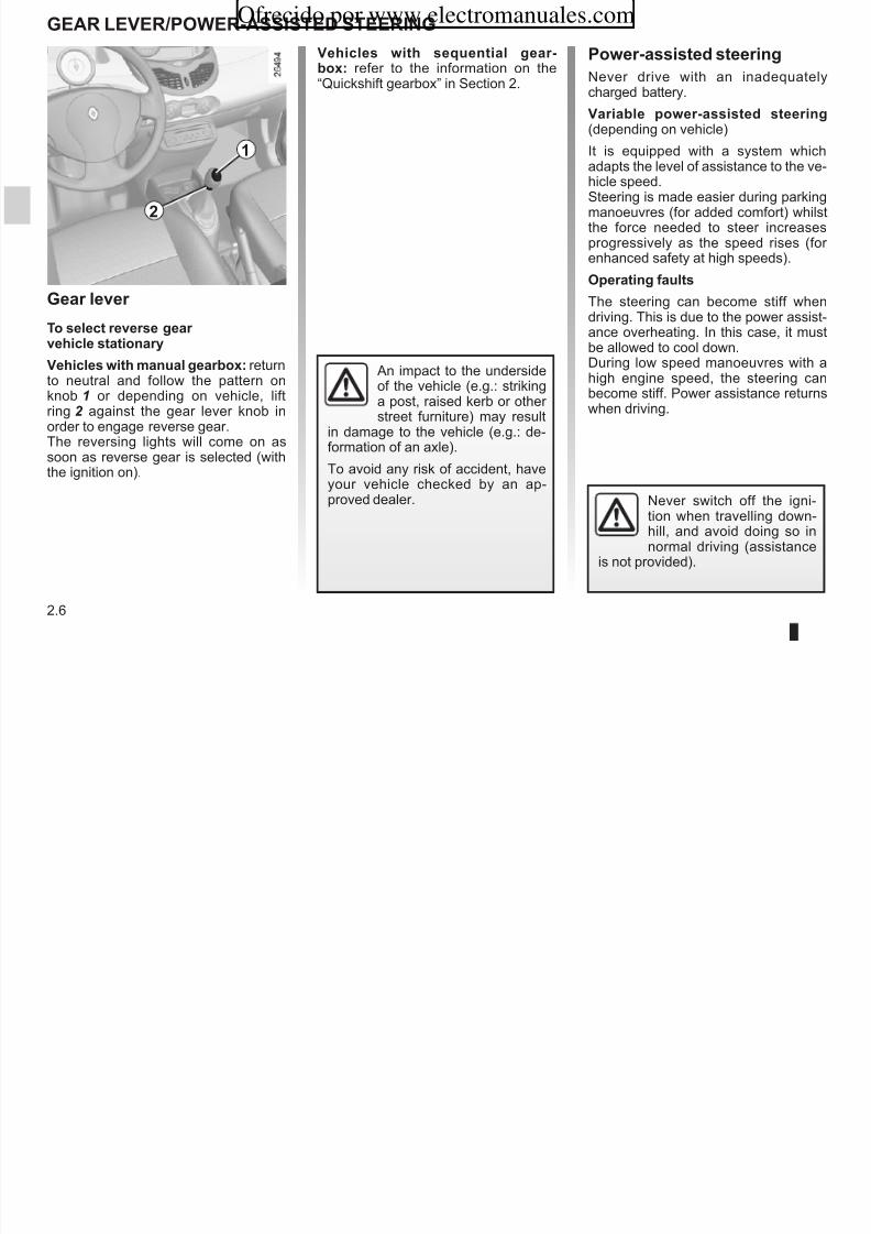
8/6/2019 NU773-8_ENG
http://slidepdf.com/reader/full/nu773-8eng 80/223
2.6
Gar r
t s rrs gar i sainary
vis i manua garbx: returnto neutral and follow the pattern onknob 1 or depending on vehicle, liftring 2 against the gear lever knob inorder to engage reverse gear.The reversing lights will come on assoon as reverse gear is selected (withthe ignition on).
2
1
(depending on vehicle)
It is equipped with a system whichadapts the level of assistance to the ve-
hicle speed.Steering is made easier during parkingmanoeuvres (for added comfort) whilstthe force needed to steer increasesprogressively as the speed rises (for enhanced safety at high speeds).
opraing faus
The steering can become stiff whendriving. This is due to the power assist-
ance overheating. In this case, it mustbe allowed to cool down.During low speed manoeuvres with ahigh engine speed, the steering canbecome stiff. Power assistance returnswhen driving.
Never switch off the igni-tion when travelling down-hill, and avoid doing so innormal driving (assistance
is not provided).
An impact to the undersideof the vehicle (e.g.: strikinga post, raised kerb or other street furniture) may result
in damage to the vehicle (e.g.: de-formation of an axle).
To avoid any risk of accident, have
your vehicle checked by an ap-proved dealer.
hANDBRAKet appy:
Pull upwards, check that the vehicle isproperly immobilised.
Ofrecido por www.electromanuales.com

8/6/2019 NU773-8_ENG
http://slidepdf.com/reader/full/nu773-8eng 81/223
2.7
t ras:
Pull the lever up slightly, press button 1
and then lower the lever to the floor.
The red warning light on the instrumentpanel will come on if you are drivingwith an incorrectly released handbrake.
1
Depending on the slopeand/or vehicle load, it maybe necessary to apply the
brake by an additional twonotches and to engage a gear (1stor reverse) for manual vehicles.
Make sure that the hand-brake is properly releasedwhen driving (red indicator light off), otherwise over-
heating, or even damage, mayoccur.
ADvIce: anipuin, fu nmy and driing (1/3)By virtue of its design, moderate fuelconsumption and initial settings, your vehicle conforms to current antipol-lution regulations. The manufacturer is actively striving to reduce pollutantexhaust gas emissions and to save
Mainnan
It is important to remember that failure torespect antipollution regulations couldlead to legal action being taken againstthe vehicle owner. In addition, replacing
engin adjusmns
– igniin: this does not require ad- justment.
– spark pugs: for optimum fuel econ-omy efficiency and performance
Ofrecido por www.electromanuales.com

8/6/2019 NU773-8_ENG
http://slidepdf.com/reader/full/nu773-8eng 82/223
2.8
exhaust gas emissions and to saveenergy. But the fuel consumption of your vehicle and the level of pollutantexhaust gas emissions are also your responsibility. Ensure that it is main-tained and used correctly.
p gengine, fuel supply system and exhaustcomponents with parts other than thoseoriginally recommended by the manu-
facturer may alter your vehicle so thatit no longer complies with antipollutionregulations.
Have your vehicle adjusted andchecked by an approved Dealer, in ac-cordance with the instructions given inyour maintenance schedule: they willhave all the equipment necessary for ensuring that your vehicle is maintained
to its original standard.
omy, efficiency and performancethe specifications laid down by our Design Department must be strictlyapplied.
If the spark plugs have to bechanged, use the make, type andgap specified for your vehicle’sengine. Contact an approved dealer for this.
– id: this does not require adjust-ment.
– air fir, dis fir: a clogged ele-
ment reduces performance. It mustbe replaced.
ADvIce: anipuin, fu nmy and driing (2/3)exaus gas mniringsysmThe exhaust gas monitoring system willdetect any operating faults in the vehi-cle’s antipollution system.If thi t lf ti t i b
– Sporty driving uses a lot of fuel: drivewith a light right foot.
– Brake as little as possible. If you an-ticipate an obstacle or bend in ad-vance, you may then simply releasethe accelerator pedal
Ofrecido por www.electromanuales.com
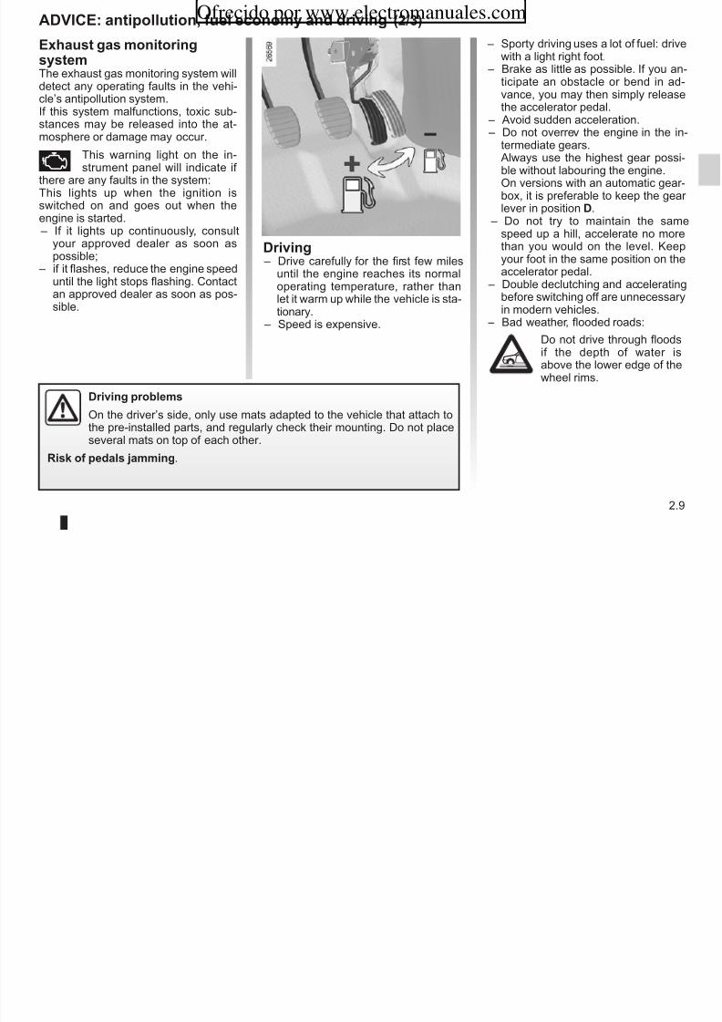
8/6/2019 NU773-8_ENG
http://slidepdf.com/reader/full/nu773-8eng 83/223
2.9
Driing – Drive carefully for the first few miles
until the engine reaches its normaloperating temperature, rather thanlet it warm up while the vehicle is sta-tionary.
– Speed is expensive.
If this system malfunctions, toxic sub-stances may be released into the at-mosphere or damage may occur.
Ä This warning light on the in-strument panel will indicate if
there are any faults in the system:This lights up when the ignition isswitched on and goes out when theengine is started. – If it lights up continuously, consult
your approved dealer as soon aspossible;
– if it flashes, reduce the engine speed
until the light stops flashing. Contactan approved dealer as soon as pos-sible.
the accelerator pedal. – Avoid sudden acceleration. – Do not overrev the engine in the in-
termediate gears.Always use the highest gear possi-ble without labouring the engine.On versions with an automatic gear-box, it is preferable to keep the gear lever in position D.
– Do not try to maintain the samespeed up a hill, accelerate no morethan you would on the level. Keepyour foot in the same position on the
accelerator pedal. – Double declutching and acceleratingbefore switching off are unnecessaryin modern vehicles.
– Bad weather, flooded roads:
Do not drive through floodsif the depth of water isabove the lower edge of thewheel rims.
Driing prbms
On the driver’s side, only use mats adapted to the vehicle that attach tothe pre-installed parts, and regularly check their mounting. Do not placeseveral mats on top of each other.
Risk f pdas jamming.
ADvIce: anipuin, fu nmy and driing (3/3) – Fr is fid i air ndi-
ining, it is normal to observe anincrease in fuel consumption (es-pecially in city conditions) whenit is used. For vehicles fitted withmanual air conditioning, switch off
Ofrecido por www.electromanuales.com

8/6/2019 NU773-8_ENG
http://slidepdf.com/reader/full/nu773-8eng 84/223
2.10
Adi n us
– Electricity is fuel; switch off all the
electrical components which arenot really needed. hr (safetyfirst), keep your lights on when thevisibility is bad (“see and be seen”).
– Use the air vents. Driving with thewindows open at 60 mph (100 km/h)will increase fuel con-sumption by4%.
– When towing a caravan, fit a wind
deflector and adjust it carefully.
manual air conditioning, switch off the system when it is not required.
Adi fr rduing nsumpin
and rfr ping prsr nirnmn:Drive with the air vents open and thewindows closed.
If the vehicle has been parked in thesun, open the doors for a few mo-ments to let the hot air escape beforestarting the engine.
– Never fill the fuel tank right to the
brim to avoid overflow. – Do not leave an empty roof rack
fitted to the vehicle.
– It is better to fit a trailer for bulky ob- jects.
– Avoid using the vehicle for door-to-door calls (short journeys with
long waits in between) because theengine never reaches its normal op-erating temperature.
tyrs
– An under-inflated tyre increases fuelconsumption.
– The use of non-recommended tyrescan increase fuel consumption.
eNvIRoNMeNtemissins
Your vehicle has been designed to emitfewer greenhouse gases (CO2) while inuse, and therefore to consume less fuel(eg. 140 g/km, equivalent to 5.3 l/100k f di l hi l )
– At the end of the vehicle’s servicelife, it should be sent to approvedcentres to ensure that it is recycled.
– In all cases, comply with local legis-lation.
Your vehicle has been designed withrespect for the nirnmn in mind for its entire service life: during production,use and at the end of its life.This commitment is illustrated by theRenault eco² group signature.
Ofrecido por www.electromanuales.com

8/6/2019 NU773-8_ENG
http://slidepdf.com/reader/full/nu773-8eng 85/223
2.11
km for a diesel vehicle).
Our vehicles are also equipped with aparticle filter system including a cata-lytic converter, an oxygen sensor andan active carbon filter (the latter pre-vents vapour from the fuel tank beingreleased into the open air).
For certain diesel vehicles, this systemalso has a particle filter to reduce thevolume of soot particles emitted.
Pas mak yur nnribuin ardspring nirnmn
– Worn parts replaced in the course of routine vehicle maintenance (vehi-cle battery, oil filter, air filter, batter-ies, etc.) and oil containers (empty or filled with used oil) must be disposed
of through specialist organisations.
Rying
Your vehicle is 85% recyclable and95% recoverable.
To achieve these objectives, many of the vehicle components have been de-signed to enable them to be recycled.The materials and structures havebeen carefully designed to allow thesecomponents to be easily removed andreprocessed by specialist companies.
In order to preserve raw material re-sources, this vehicle incorporates nu-merous parts made from recycled plas-tics or renewable materials (vegetableor animal-derived materials such ascotton or wool).
g p g
Manufaur
Your vehicle has been manufactured at
an industrial site which uses a progresspolicy to reduce environmental impactson rivers and natural areas (reduc-tion of water and energy consumption,visual and noise pollution, atmosphericemissions and waste water, sorting andreusing waste).
DRIvING coRRectIoN DevIceDepending on the vehicle, this is com-posed of: – ABS (ani-k braking sysm); – rni sabiiy prgram (eSP)
i undrsr nr and ra-in nr (ASR);
opraing faus:
– If indicator lightsx and©light up on the instrument panel,braking is si praina buiu ABS;
ABS (Ani-k BrakingSysm)Under heavy braking, the ABS preventsthe wheels from locking, allowing thestopping distance to be managed andkeeping control of the vehicle
Ofrecido por www.electromanuales.com

8/6/2019 NU773-8_ENG
http://slidepdf.com/reader/full/nu773-8eng 86/223
2.12
( ); – mrgny brak assis.
In an emergency, apply firm andninuus prssur to the brakepedal. There is no need to pumpit repeatedly. The ABS will modu-late the force applied in the brakingsystem.
These functions are an ad-ditional aid in the event of critical driving conditions,enabling the vehicle behav-
iour to be adapted to suit the driving
conditions.
However, the functions do not takethe place of the driver. ty dn inras i’s imisand sud n nurag yu dri mr quiky. Therefore,they can under no circumstancesreplace the vigilance or responsibil-ity of the driver when manoeuvring
the vehicle (the driver must alwaysbe ready for sudden incidents whichmay occur when driving).
Your braking systemsare partially operational.However, it is dangrus
brak suddny andit is essential to stop immediately,as soon as traffic conditions allow.Contact an approved dealer.
;
– If indicator lightsx ,û ,
© andD are displayed onthe instrument panel when driving,is indias r is a fau i braking sysm and ABS.
In both cases, consult an approvedDealer.
keeping control of the vehicle.
Under these circumstances, the vehi-cle can be steered to avoid an obstacle
whilst braking. In addition, this systemcan increase stopping distances, par-ticularly on roads with low surface grip(wet ground, etc.).
You will feel a pulsation through thebrake pedal each time the system isactivated. The ABS does not in any wayimprove the vehicle’s physical perform-ance relating to the road surface and
roadholding. It is still ssnia to followthe rules of good driving practice (suchas driving at a safe distance from thevehicle in front).
DRIvING coRRectIoN DevIce (ninud)erni sabiiy prgram(eSP) i undrsr nrand rain nr (ASR)
When the function begins to operate,
warning lightù flashes to warn
erni Sabiiy Prgram (eSP)
This system helps you to keep controlof the vehicle in critical driving condi-tions (avoiding an obstacle, loss of gripon a bend, etc.).
train nr (ASR)
This system helps to limit wheelspin of the drive wheels and to control the ve-hicle when pulling away accelerating or decelerating.
o i i i
Ofrecido por www.electromanuales.com

8/6/2019 NU773-8_ENG
http://slidepdf.com/reader/full/nu773-8eng 87/223
2.13
warning lightù flashes to warnyou. opraing prinip
A sensor in the steering wheel detects
the direction selected by the driver.Other sensors throughout the vehiclemeasure the actual direction.
The system compares the direction se-lected by the driver and the actual di-rection of the vehicle and corrects thisas necessary by applying the brakesselectively and/or acting on the enginepower.
Undrsr nr
This system optimises the action of theESP in the case of pronounced unders-teering (loss of front axle road holding).
opraing prinipUsing the wheel sensors, the systemmeasures and compares the speed of
the drive wheels at all times and slowsdown their over-rotation. If a wheel isstarting to slip, the system brakes au-tomatically until the drive supplied be-comes compatible with the level of gripunder the wheel again.
The system also adjusts the enginespeed to the grip available under thewheels, independently of the pressure
exerted on the accelerator pedal.
emrgny brak assis
This is an additional system to ABSwhich helps reduce vehicle stoppingdistances.
opraing prinip
DRIvING coRRectIoN DevIce (ninud)Spia n n is i aQuiksif garbx
When driving on some roads with lowsurface grip (grass, snow, mud, etc.),the system may reduce the engineoutput to limit wheelspin. If this is not
Ofrecido por www.electromanuales.com

8/6/2019 NU773-8_ENG
http://slidepdf.com/reader/full/nu773-8eng 88/223
2.14
opraing prinip
The system detects an emergencybraking situation. In this case, the brak-
ing assistance immediately developsmaximum power and may trigger ABSregulation.
ABS braking is maintained as long asthe brake pedal is not released.
hazard arning igs siing nDepending on the vehicle, these maylight up in the event of sudden decel-
eration.
output to limit wheelspin. If this is notrequired, it is recommended to switchto manual mode on the Quickshift gear-
box (using the gear lever).
opraing faus
When the system detects an operating
fault, indicator lightsù and© light up on the instrument panel. In thissituation, ESP and ASR are deacti-vated.
Consult an approved dealer.
cRUISe coNtRol - SPeeD lIMIteR: imir funin (1/3)
Ofrecido por www.electromanuales.com

8/6/2019 NU773-8_ENG
http://slidepdf.com/reader/full/nu773-8eng 89/223
2.15
The speed limiter function helps youstay within the driving speed limit thatyou choose, known as the imi spd.
cnrs
1 Main “On/Off” switch.
2 Limit speed activation, storage andincrease switch (+).
3 Limit speed activation, storage anddecrease switch (-).
4 Switch the function to standby, withlimit speed stored (O).
5 Stored limit speed activation, stor-age and recall (R).
Siing nPress switch 1 on the side showing.
Warning light 6 comes on and dashesappear on the instrument panel to in-dicate that the speed limiter functionis operating and waiting to store a limitspeed.To store the current speed, pressswitch 2 (+) or 3 (-): the limit speedwill replace the dashes. The minimumstored speed is 20 mph (30 km/h).The stored speed information appears
on instrument panel display .
6
1
3 4 52
cRUISe coNtRol - SPeeD lIMIteR: imir funin (2/3)varying imi spd
You can vary the limit speed by press-ing switch 2 (+) repeatedly to increasethe speed or switch 3 (-) to decrease it.
e di i i d
limid spd ann b mainaind
When driving down a steep gradient,the system is unable to maintain thelimit speed: the memorised speed willflash on the instrument panel informa-tion display to inform you of this situ-2 3 4 5
Ofrecido por www.electromanuales.com
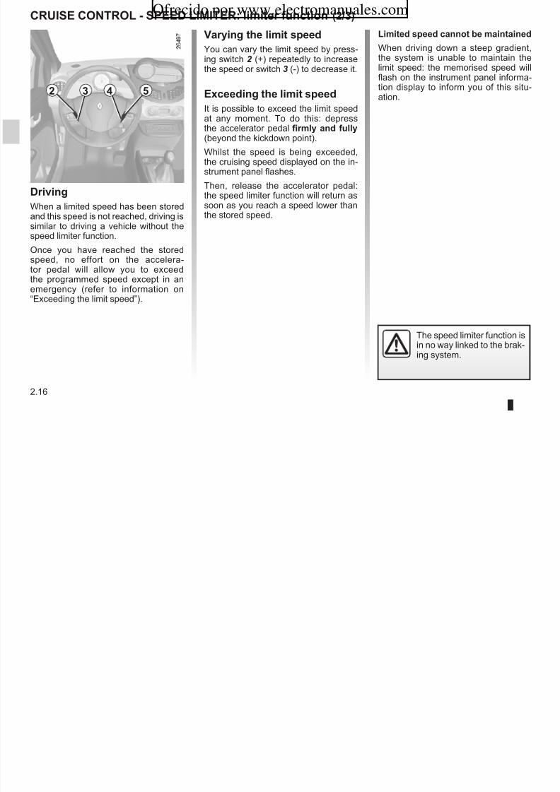
8/6/2019 NU773-8_ENG
http://slidepdf.com/reader/full/nu773-8eng 90/223
2.16
Driing
When a limited speed has been stored
and this speed is not reached, driving issimilar to driving a vehicle without thespeed limiter function.
Once you have reached the storedspeed, no effort on the accelera-tor pedal will allow you to exceedthe programmed speed except in anemergency (refer to information on“Exceeding the limit speed”).
exding imi spd
It is possible to exceed the limit speed
at any moment. To do this: depressthe accelerator pedal firmy and fuy (beyond the kickdown point).
Whilst the speed is being exceeded,the cruising speed displayed on the in-strument panel flashes.
Then, release the accelerator pedal:the speed limiter function will return assoon as you reach a speed lower than
the stored speed.
p y yation.
The speed limiter function isin no way linked to the brak-ing system.
2 3 4 5
cRUISe coNtRol - SPeeD lIMIteR: imir funin(3/3)
Raing imi spd
If a speed has been stored, it can be re-called by pressing switch 5 (R).
2 3 4 5
Ofrecido por www.electromanuales.com

8/6/2019 NU773-8_ENG
http://slidepdf.com/reader/full/nu773-8eng 91/223
2.17
Puing funin nsandby
The speed limiter function is suspendedwhen you press switch 4 (O).
In this case, the programmed limitspeed is memorised and the speed dis-played on the instrument panel appearsin brackets to confirm the function is onstandby.
When the speed limiter is sus-
pended, pressing switch 2 (+) or 3 (-) reactivates the function with-out taking into account the storedspeed: it is the speed at which thevehicle is moving that is taken intoaccount.
Siing ff funin
The speed limiter function is deacti-
vated if you press switch 1: in this casea speed is no longer stored. The in-strument panel indicator light goes out,confirming that the function is deacti-vated.
2 3 4 5
1
cRUISe coNtRol - SPeeD lIMIteR: ruis nr funin (1/4)
2 3 4 5
Ofrecido por www.electromanuales.com

8/6/2019 NU773-8_ENG
http://slidepdf.com/reader/full/nu773-8eng 92/223
2.18
The cruise control function helps you tomaintain your driving speed at a speedthat you choose, called the ruisingspd.
This cruising speed may be set at anyspeed above 20 mph (30 km/h).
The cruise control functionis in no way linked to thebraking system.
This function is an addi-tional driving aid. However,the function does not takethe place of the driver.
Therefore, it can under no circum-stances replace the driver’s respon-sibility to respect speed limits and to
be vigilant (the driver must alwaysbe ready to brake).
Cruise control must not be usedin heavy traffic, on winding or slip-pery roads (black ice, aquaplan-ing, gravel) and during bad weather (fog, rain, side winds etc.).
There is a risk of accidents.
cnrs
1 Main “On/Off” switch.
2 Cruising speed activation, storageand increase switch (+).
3 Cruising speed activation, storageand decrease switch (-).
4 Switch the function to standby (withstored cruising speed) (O).
5 Cruising speed activation, storageand recall switch (R).
1
cRUISe coNtRol - SPeeD lIMIteR: ruis nr funin (2/4)
2 3 4 5
Ofrecido por www.electromanuales.com

8/6/2019 NU773-8_ENG
http://slidepdf.com/reader/full/nu773-8eng 93/223
2.19
Siing n
Press switch 1 on the side showing.
Warning light 6 comes on and dashesappear on the instrument panel to indi-cate that the cruise control function isoperating and waiting to store a cruis-ing speed.
Aiaing ruis nr
At a steady speed (above 20 mph
30 km/h) press switch 2 (+) or 3 (-): thefunction is activated, the current speedis stored and replaces the dashes onthe instrument panel.
Cruise control activation is confirmedwhen the box around indicator light 6 isilluminated.
Driing
Once a cruising speed is stored and
the cruise control function is active,you may lift your foot off the accelera-tor pedal.
Important: you are never-theless advised to keepyour feet close to the pedalsin order to react if neces-
sary.
6
1
cRUISe coNtRol - SPeeD lIMIteR: ruis nr funin (3/4)
exding ruising spd
The cruising speed may be exceededat any time by depressing the accelera-tor pedal. While it is being exceeded,the cruising speed flashes on the in-strument panel.2 3 4 5
Ofrecido por www.electromanuales.com

8/6/2019 NU773-8_ENG
http://slidepdf.com/reader/full/nu773-8eng 94/223
2.20
Adjusing ruising spd
The cruising speed may be changed by
pressing the following repeatedly: – switch2 (+) to increase the speed,
– switch3 (-) to decrease the speed.
The cruise control functionis in no way linked to thebraking system.
Then, release the accelerator: after afew seconds, the vehicle will automati-
cally return to its set cruising speed.
cruising spd ann bmainaind
When driving down a steep gradient,the system is unable to maintain thecruising speed: the stored speed willflash on the instrument panel informa-tion display to inform you of this situ-
ation.
2
cRUISe coNtRol - SPeeD lIMIteR: ruis nr funin (4/4)
Rurning ruising spd
If a speed is stored, it can be recalled,once you are sure that the road condi-tions are suitable (traffic, road surface,weather conditions, etc.). With the ve-hicle speed above 20 mph (30 km/h),press switch 5 (R)
2 3 4 5
Ofrecido por www.electromanuales.com

8/6/2019 NU773-8_ENG
http://slidepdf.com/reader/full/nu773-8eng 95/223
2.21
Puing funin nsandby
The cruise control function is sus-pended when you press:
– press switch4 (O); – the brake pedal; – depress the clutch pedal or shift into
neutral if the vehicle has a Quickshiftgearbox.
In all three cases, the cruising speedis stored. The speed appears between
brackets on the display and the boxaround the indicator light goes out toconfirm the function is on standby.
press switch 5 (R).
When recalling the stored speed, acti-
vation of the cruise control is confirmedby the illumination of the strip aroundthe indicator light.
N: if the speed previously stored ismuch higher than the current speed,the vehicle will accelerate more rapidlyto reach this threshold.
When the cruise control is sus-
pended, pressing switch 2 (+) or 3 (-) reactivates the cruise controlfunction without taking into accountthe stored speed: it is the speed atwhich the vehicle is moving that istaken into account.
Siing ff funin
The cruise control function is deacti-
vated if you press switch 1: in this casea speed is no longer stored. The in-strument panel indicator light goes out,confirming that the function is stopped.
Putting the cruise control
on standby or switching itoff does not cause a rapidreduction in speed: you
must brake by depressing the brakepedal.
1
QUIcKShIFt GeARBoX (1/5)
4
1
Ofrecido por www.electromanuales.com

8/6/2019 NU773-8_ENG
http://slidepdf.com/reader/full/nu773-8eng 96/223
2.22
Gar sif parn
A/M to change mode (automatic/
manual)+ to change up a gear
– to change down
N neutral
R reverse
For safety reasons, do notswitch off the ignition beforethe vehicle has come to acomplete standstill.
Dispay
2 automatic mode
3 selected gear display
4 brake pedal depressed indicator light
2
3
Sr r 1
– This allows you to engage first gear,
to select reverse and neutral and tochange gear in manual mode.
– It also allows you to switch betweenmanual and automatic modes at anytime, with the engine switched onand a forwards gear engaged, bymoving the lever to the left.
Saring
The display shows N (neutral) and A (automatic mode).
Frards gar
– With the brake pedal depressed,push the selector lever forwards and
oprain
Switch on the ignition.
The display on the instrument panelswitches on. If neutral (N) is displayed,start the engine but do not depress theaccelerator.
QUIcKShIFt GeARBoX (2/5)
4
Ofrecido por www.electromanuales.com
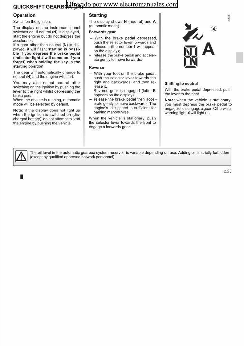
8/6/2019 NU773-8_ENG
http://slidepdf.com/reader/full/nu773-8eng 97/223
2.23
push the selector lever forwards andrelease it (the number 1 will appear
on the display); – release the brake pedal and acceler-ate gently to move forwards.
Rrs
– With your foot on the brake pedal,push the selector lever towards theright and backwards, and then re-lease it.Reverse gear is engaged (letter R
appears on the display). – release the brake pedal then accel-
erate gently to move backwards. Theengine’s idle speed is sufficient for parking manoeuvres.
When the vehicle is stationary, pushthe selector lever towards the front toengage a forwards gear.
If a gear other than neutral (N) is dis-played, it will flash; saring is pssi-
b if yu dprss brak pda(indiar ig 4 i m n if yufrg) n ding ky in saring psiin.
The gear will automatically change toneutral (N) and the engine will start.
You may also select neutral after switching on the ignition by pushing thelever to the right whilst depressing the
brake pedal.When the engine is running, automaticmode will be selected by default.
N: if the display does not light upwhen the ignition is switched on (dis-charged battery), do not attempt to startthe engine by pushing the vehicle.
Sifing nura
With the brake pedal depressed, push
the lever to the right.N: when the vehicle is stationary,you must depress the brake pedal toengage or disengage a gear. Otherwise,warning light 4 will light up.
The oil level in the automatic gearbox system reservoir is variable depending on use. Adding oil is strictly forbidden(except by qualified approved network personnel).
canging md
You can change mode at any timeby pushing the lever to the left. Thisswitches mode without changing gear.
Driing in manua md
By pushing the lever forwards twiceyou can move up two gears at a time(unless this causes low engine speeds).By pushing the lever backwards twiceyou can move down two gears at a time(unless this causes overrevving).
N: neutral may only be selected
QUIcKShIFt GeARBoX (3/5)
Driing in aumai md
Each time the ignition is switched on,automatic mode is selected by default(letter A on the display).
The vehicle is controlled using the ac-celerator and the brake.G ill h t ti ll t
Ofrecido por www.electromanuales.com
8/6/2019 NU773-8_ENG
http://slidepdf.com/reader/full/nu773-8eng 98/223
2.24
g
Using sr r
Pushing the lever repeatedly allowsyou to change gears manually:
– To change up a gear: push the lever forwards;
– to change down a gear: push thelever backwards;
– to change to neutral: with the brakepedal depressed (indicator light 4 will come on if you forget), push thelever towards the right.
N: when the vehicle is stationary(braking, red light, etc.), the system au-tomatically switches to first gear.
N: neutral may only be selectedwhen the vehicle is being driven or is
stationary when brak pda isdprssd (if yu frg, arningig 4 i ig up).
Araing and raking
To obtain maximum vehicle perform-ance, in automatic or manual mode,quickly depress the accelerator pedalbeyond the kickdown point.
This will activate the kickdown func-
tion allowing you to change down to themost suitable gear.
Gears will change automatically atthe correct moment and at a suitable
engine speed because automatic modetakes into consideration the road sur-face and the chosen driving style.
You may change the gear selectionmade by the automatic system (unlessthis risks the engine being overrevvedor underrevved):
– by pushing the lever forwards or backwards.
You can stop the vehicle at red lights,with the gear engaged, by pressing thebrake pedal; there is no need to changeto neutral.
If the engine is being overrevved or underevved, the system will select the opti-mal gear.
QUIcKShIFt GeARBoX (4/5)
Parking
To park the vehicle with a gear en-gaged (on a slope, for example): beforeswitching off the engine, check that agear other than N is displayed on theinstrument panel.
The ne t time the engine is started de
Audib arning
If you hold the vehicle on a slope for too long without applying the brakes or handbrake you will strain the systemand there is a risk that the clutch willoverheat.
In this case an intermittent beeping
Ofrecido por www.electromanuales.com

8/6/2019 NU773-8_ENG
http://slidepdf.com/reader/full/nu773-8eng 99/223
2.25
The next time the engine is started, de-press the brake pedal. The vehicle will
then automatically change to neutral(letter N on the display).
In this case, an intermittent beepingsound will remind you that you should
put your foot on the brake pedal or apply the handbrake.
Never leave the vehicle with the enginerunning when in gear. For safety rea-sons you will hear an intermittent beep-ing sound when you open the door if you have not shifted into neutral or youhave not switched off the ignition or de-pressed the brake pedal.
An impact to the underside of the vehicle (e.g.: striking a post, raised kerb
or other street furniture) may result in damage to the vehicle (e.g.: defor-mation of an axle).
To avoid any risk of accident, have your vehicle checked by an approvedDealer.
QUIcKShIFt GeARBoX (5/5)
ting i
If the gearbox is stuck in a gear:
– Switch on the ignition;
– select neutrali brak pdadprssd;
– check that the gearbox is in neutral
opraing faus
Ò When driving, if this warninglight comes on together with
warning light©, this indicates asystem fault. In most cases, you maystill drive the vehicle, although it will notfunction perfectly. Contact an approved
Ofrecido por www.electromanuales.com

8/6/2019 NU773-8_ENG
http://slidepdf.com/reader/full/nu773-8eng 100/223
2.26
check that the gearbox is in neutral(by pushing the vehicle, for exam-
ple).If you cannot find neutral you must towthe vehicle with the front wheels raised.
t i sud aays b di igniin sid ff.
function perfectly. Contact an approveddealer as soon as possible.
t i i n sar
If you cannot start the engine and if thebattery is not discharged (display lit up):
– Switch on the ignition;
– select neutral;
– push the vehicle or roll it down a suf-ficiently steep slope. Then push theselector lever forwards.
The optimum gear for starting theengine will then be automatically se-lected.
N: never attempt this manoeuvre inreverse.
PARKING DIStANce coNtRol (1/2)
opraing prinip
Ultrasonic sensors, fitted in the vehi-cle’s rear bumper, measure the dis-tance between the vehicle and an ob-stacle when reversing.
This measurement is indicated bybeeps which become more frequent the
Ofrecido por www.electromanuales.com

8/6/2019 NU773-8_ENG
http://slidepdf.com/reader/full/nu773-8eng 101/223
2.27
beeps which become more frequent thecloser you come to the obstacle, until
they become a continuous beep whenthe vehicle is approximately 30 centi-metres from the obstacle.
There is a beep when changing to re-verse gear.
N: make sure that the ultrasonicsensors are not obscured (by dirt, mud,snow, etc.).
opraing faus
When the system detects an operating
fault there will be a 5-second, continu-ous warning beep when reverse gear isselected. Consult an approved dealer.
This function is an addi-tional aid that indicates thedistance between the vehi-cle and an obstacle whilst
reversing, using sound signals.
Under no circumstances should itreplace the driver’s care or respon-sibility whilst reversing.
The driver should always pay at-tention to sudden incidents duringdriving: always ensure that thereare no moving obstacles (such as achild, animal, pram or bicycle, etc.)or small, narrow objects such asstones or posts in your path whenmanoeuvring.
An impact to the underside of the vehicle (e.g.: striking a post, raised kerb
or other street furniture) may result in damage to the vehicle (e.g.: defor-mation of an axle).
To avoid any risk of accident, have your vehicle checked by an approveddealer.
Prngd daiain f sysm
You can deactivate the system for pro-longed periods by pressing the switchfor longer than approximately threeseconds.
The warning light built into the switch
PARKING DIStANce coNtRol (2/2)
1
Ofrecido por www.electromanuales.com

8/6/2019 NU773-8_ENG
http://slidepdf.com/reader/full/nu773-8eng 102/223
2.28
tmprary daiain f sysm
Press switch 1 to deactivate the system.The indicator light built into the switchlights up to remind you that the systemis deactivated.
Pressing the switch again will reacti-vate the system and switch off the in-dicator light.
The system is automatically reactivatedafter the ignition is switched off and the
engine restarted.
The warning light built into the switchremains lit constantly.
Once deactivated, the system canbe reactivated by pressing the buttonagain for longer than approximatelythree seconds.
1
Section 3: Your comfort
Ofrecido por www.electromanuales.com

8/6/2019 NU773-8_ENG
http://slidepdf.com/reader/full/nu773-8eng 103/223
3.1
Air vents: air outlets . . . . . . . . . . . . . . . . . . . . . . . . . . . . . . . . . . . . . . . . . . . . . . . . . . . . . . . . . . . . . . 3.2Manual air conditioning . . . . . . . . . . . . . . . . . . . . . . . . . . . . . . . . . . . . . . . . . . . . . . . . . . . . . . . . . . . 3.4Heating - air conditioning . . . . . . . . . . . . . . . . . . . . . . . . . . . . . . . . . . . . . . . . . . . . . . . . . . . . . . . . . . 3.7Automatic climate control . . . . . . . . . . . . . . . . . . . . . . . . . . . . . . . . . . . . . . . . . . . . . . . . . . . . . . . . . 3.9Air conditioning: information and advice on use . . . . . . . . . . . . . . . . . . . . . . . . . . . . . . . . . . . . . . . . 3.18Interior lighting . . . . . . . . . . . . . . . . . . . . . . . . . . . . . . . . . . . . . . . . . . . . . . . . . . . . . . . . . . . . . . . . . . 3.19Electric windows . . . . . . . . . . . . . . . . . . . . . . . . . . . . . . . . . . . . . . . . . . . . . . . . . . . . . . . . . . . . . . . . 3.20Sun visor/Courtesy mirrors/Windscreen . . . . . . . . . . . . . . . . . . . . . . . . . . . . . . . . . . . . . . . . . . . . . . 3.23Electric sunroof . . . . . . . . . . . . . . . . . . . . . . . . . . . . . . . . . . . . . . . . . . . . . . . . . . . . . . . . . . . . . . . . . 3.24Passenger compartment storage/Fittings . . . . . . . . . . . . . . . . . . . . . . . . . . . . . . . . . . . . . . . . . . . . . 3.26Ashtray/cigar lighter/accessories socket . . . . . . . . . . . . . . . . . . . . . . . . . . . . . . . . . . . . . . . . . . . . . . 3.30Rear headrests . . . . . . . . . . . . . . . . . . . . . . . . . . . . . . . . . . . . . . . . . . . . . . . . . . . . . . . . . . . . . . . . . 3.31Rear seats: adjustments . . . . . . . . . . . . . . . . . . . . . . . . . . . . . . . . . . . . . . . . . . . . . . . . . . . . . . . . . . 3.32Rear seats: functions . . . . . . . . . . . . . . . . . . . . . . . . . . . . . . . . . . . . . . . . . . . . . . . . . . . . . . . . . . . . . 3.33
Rear bench seat: functions . . . . . . . . . . . . . . . . . . . . . . . . . . . . . . . . . . . . . . . . . . . . . . . . . . . . . . . . 3.34Luggage compartment. . . . . . . . . . . . . . . . . . . . . . . . . . . . . . . . . . . . . . . . . . . . . . . . . . . . . . . . . . . . 3.35
Rear parcel shelf . . . . . . . . . . . . . . . . . . . . . . . . . . . . . . . . . . . . . . . . . . . . . . . . . . . . . . . . . . 3.36Luggage compartment cover: utility versions . . . . . . . . . . . . . . . . . . . . . . . . . . . . . . . . . . . . . . . . . . 3.38Transporting objects in the luggage compartment . . . . . . . . . . . . . . . . . . . . . . . . . . . . . . . . . . . . . . 3.39Roof bars . . . . . . . . . . . . . . . . . . . . . . . . . . . . . . . . . . . . . . . . . . . . . . . . . . . . . . . . . . . . . . . . . . . . . . 3.40
1 2 3 4 5 6 1
AIR VENTS: air tets (1/2)Ofrecido por www.electromanuales.com

8/6/2019 NU773-8_ENG
http://slidepdf.com/reader/full/nu773-8eng 104/223
3.2
1 side window demister outlet
2 left-hand side vent
3 windscreen demister outlets
4 centre air vents
5 control panel
6 right-hand side vent
7 front occupant footwell heater out-lets
77
1
3 3
To remove bad odours from your ve-hicles, only use the systems designedfor this purpose. Consult an approvedDealer.
AIR VENTS: air tets (2/2)Ofrecido por www.electromanuales.com

8/6/2019 NU773-8_ENG
http://slidepdf.com/reader/full/nu773-8eng 105/223
3.3
2
4
Side air vents
Air fw
Move wheel 2 fully.
: maximum air flow
: closed.
Directin
Right/left: move tab 1.
Up/down: guide the air vent up or down.
Centre air vents
Air fw
Move wheel 4 fully.
: maximum air flow
: closed.
Directin
Right/left: move tabs 3.
Up/down: guide the air vent up or down.Do not add anything to the
vehicle’s ventilation circuit(for example, to removebad odours).
Tere is a ris f damae r f fire.
MANuAl AIR CoNDITIoNINg (1/3)
Distribtin f air in tepassener cmpartment
Turn control A.
W Cse te dasbard ventsfr mre effective demistin.
All the air is then directed to the wind-screen and front side window demister
A B C E FD
Ofrecido por www.electromanuales.com

8/6/2019 NU773-8_ENG
http://slidepdf.com/reader/full/nu773-8eng 106/223
3.4
Cntrs
A Adjusting the distribution of air in the
passenger compartment.B Heated rear screen and heated door
mirror button and indicator light (de-pending on vehicle).
C Adjusting the ventilation speed.
D Air recirculation and isolation of thepassenger compartment.
E Air conditioning button and operatingtell-tale (depending on vehicle).
F Adjusting the air temperature.
Infrmatin and advice fr se:
Refer to the end of the paragraph on“Automatic climate control”.
outlets.
i The air flow is distributed be-tween all the air vents, the
front side window demisting vents, thewindscreen demisting vents and thefootwells.
F The air flow is directed mainlytowards the footwells.
Adjstin te ventiatinspeed
Turn control C from 0 to 4.
The passenger compartment is ven-tilated by blown air. The blower deter-mines how much air enters but vehiclespeed has a slight effect on this.
B C
MANuAl AIR CoNDITIoNINg (2/3)Ofrecido por www.electromanuales.com

8/6/2019 NU773-8_ENG
http://slidepdf.com/reader/full/nu773-8eng 107/223
3.5
G The air flow is directed towardsthe dashboard vents and the
footwells.
J All the air flow is directed to thedashboard vents.
This selection is not appropriate if allthe air vents are closed.
Rear screen de-icin/demistin
With the engine running, pressbutton B, the operating tell-tale for thebutton will come on.
This function permits rapid demisting/de-icing of the rear screen and de-icingof the door mirrors (on equipped vehi-cles).
To exit this function, press button B again.
Demisting automatically stops by de-fault.
p g
The further the control is positioned tothe right, the greater the amount of air blown into the passenger compartment.
Prolonged use of this position (iso-lation mode) may mist up the win-dows slightly or cause odours dueto the air not being renewed.It is therefore advisable to return to
D
MANuAl AIR CoNDITIoNINg (3/3)Ofrecido por www.electromanuales.com

8/6/2019 NU773-8_ENG
http://slidepdf.com/reader/full/nu773-8eng 108/223
3.6
Air recircatin peratin(isatin f te passener cmpartment)
Turn control D towards air recirculationsymbolâ.
In these conditions air is taken from thepassenger compartment and is recircu-lated, with no air being taken from out-side the vehicle.
Air recircatin is fr:
– isolating the vehicle from the exter-nal atmosphere (driving in pollutedareas, etc.);
– bringing the passenger compartmentto the desired temperature as quicklyas possible.
normal operation (external air) by
pressing control D when you havepassed through the polluted area.
hEATINg – AIR CoNDITIoNINg (1/2)
Nte: The air conditioning may be usedin all conditions but does not operatewhen the external temperature is low.
– Bttn E nt activated (indicatr interated int te bttn nt i-minated).
The air conditioning is not operating.The heating and ventilation controls
C E
Ofrecido por www.electromanuales.com

8/6/2019 NU773-8_ENG
http://slidepdf.com/reader/full/nu773-8eng 109/223
3.7
Air cnditinin cntrs
Button E switches the air conditioningon or off.
The system cannt be switced n if control C is set to 0.
Using the air conditioning system ena-bles you to:
– lower the internal passenger com-partment temperature, especially inhot weather, when driving in traffic or when the vehicle has been parked inthe sun;
– reduce the humidity of the air blowninto the passenger compartment (re-moval of condensation).
Fuel consumption increases when theair conditioning system is being used
(switch it off when it is not required).
The heating and ventilation controls
are the same as a vehicle without air conditioning.
– Bttn E activated (indicatr in-terated int te bttn imi-nated).
The air conditioning is operating.
hEATINg – AIR CoNDITIoNINg (2/2)
If n cd air is prdced
Check that the controls are set correctlyand that the fuses are sound. If they arenot, switch off the heating and air con-ditioning system (indicator integratedinto button E ) and contact an approveddealer.
FE
Ofrecido por www.electromanuales.com

8/6/2019 NU773-8_ENG
http://slidepdf.com/reader/full/nu773-8eng 110/223
3.8
In very hot weather or when the vehiclehas been parked in the sun, open thedoors for a few moments to let the hot
air escape before starting the engine.Use the passenger compartment isola-tion function to lower the temperatureas quickly as possible to the requiredcomfort level. Switch off the air recircu-lation function once a comfortable levelhas been reached.
When the air conditioning system is op-erating, all windows must be closed for maximum efficiency.
If there is an operating fault, contact anapproved dealer.
Adjstin te air temperatre.Move control F to obtain the desiredtemperature. The further the control isin the red, the more the temperature willbe increased.
Do not open the refrigerantfluid circuit. The fluid maydamage eyes or skin.
AuToMATIC ClIMATE CoNTRol (1/9)
12 Heated rear screen with demistingfunction and heated door mirrors(depending on vehicle).
13 Heated rear screen warning light.
14 Air recirculation control.
Infrmatin and advice n se: refer t th d f th h “H ti /
1 2 3 4 5 6 7 8
914
Ofrecido por www.electromanuales.com

8/6/2019 NU773-8_ENG
http://slidepdf.com/reader/full/nu773-8eng 111/223
3.9
Te cntrs
1 Clear View button to demist and
de-ice the windows.
2 Clear View function indicator light.
3 Air conditioning on and off.
4 and 7 Adjusting the air temperature.
5 Display.
6 Automatic mode on and off.
8 and 10 Adjusting the distribution of air in the passenger com-partment.
9 and 11 Adjusting the ventilationspeed.
to the end of the paragraph on “Heating/
air conditioning”.
Buttons 1 and 12 are comple-mented by operating indicator lights(2 and 13):
– indicator light on, the function is
switched on; – indicator light off, the function is
switched off.
10111213
AuToMATIC ClIMATE CoNTRol (2/9)
– press button7 to increase the tem-perature;
– press button4 to decrease the tem-perature.
Nte: The maximum and minimumsettings of 15°C and 27°C allow thesystem to produce a minimum or maxi-mum temperature, whatever the ambi-
4 76
Ofrecido por www.electromanuales.com

8/6/2019 NU773-8_ENG
http://slidepdf.com/reader/full/nu773-8eng 112/223
3.10
Ambient temperatre:atmatic mde
Atmatic mdePress button 6 .
on te temperatre and te AuTo smb are dispaed.
Functions managed in automatic modeare not displayed.
p ,
ent conditions.
In automatic mode (AUTO indicator light on the display is lit), all heatingand air conditioning functions arecontrolled by the system.
When you modify certain functionsthe AUTO indicator light goes out.Only the modified function is notcontrolled by the system.
The automatic climate controlsystem guarantees comfort in thepassenger compartment and goodvisibility (except in the event of ex-
treme conditions), while optimisingconsumption.
Tis is te recmmended mdef se.
AuToMATIC ClIMATE CoNTRol (3/9)
Ambient temperatre:(atmatic mde) (cntined)
operatin
To reach and keep the chosen comfortlevel and to maintain good visibility, thesystem controls:
– ventilation speed;
Ofrecido por www.electromanuales.com

8/6/2019 NU773-8_ENG
http://slidepdf.com/reader/full/nu773-8eng 113/223
3.11
ventilation speed;
– air distribution; – air recirculation management;
– air conditioning start/stop;
– air temperature.
The displayed temperature valuesshow a comfort level.
When the vehicle is started in coldor hot weather, increasing or de-creasing the value displayed doesnot mean that the temperature isreached more quickly. Whatever theindicated temperature may be, thesystem optimises the increase or
decrease in temperature (the venti-lation system does not start instantlyat maximum speed: it gradually in-creases until the engine tempera-ture is sufficient, which may takefrom a few seconds to several min-utes).
Generally speaking, unless there isa particular reason not to, the dash-board air vents should remain open.
AuToMATIC ClIMATE CoNTRol (4/9)
5
Ofrecido por www.electromanuales.com

8/6/2019 NU773-8_ENG
http://slidepdf.com/reader/full/nu773-8eng 114/223
3.12
Adjstin atmatic mde
Automatic mode is the normal operat-ing mode of the system (AUTO indica-tor light lit on display 5) but you mayalter the selections made by the system(air distribution, etc.). These optionsare explained on the following pages.
Tis is te recmmended mdef se: the automatic heating andair conditioning system guaranteescomfort (except in the event of ex-treme conditions) in the passenger compartment and good visibility
while optimising consumption.Retrn t atmatic mde assn as pssibe.
AuToMATIC ClIMATE CoNTRol (5/9)
ö The air flow is directed towardsall the air vents and the pas-
senger footwells.
ó The air flow is directed mainlytowards the footwells.
5 6 8
Ofrecido por www.electromanuales.com

8/6/2019 NU773-8_ENG
http://slidepdf.com/reader/full/nu773-8eng 115/223
3.13
Distribtin f air in tepassener cmpartment
There are five possible combinationsfor air distribution, which may be se-lected by pressing buttons 8 and 10 re-peatedly. The arrows on display 5 indi-cate the setting selected:
õ All the air flow is directed to thedemisting vents for the wind-
screen and the side windows.
÷ The air flow is directed to thewindscreen and side window
demisting vents, and the passenger footwells.
ô The air flow is directed to allthe air vents. The manual air distribution option
causes the operating tell-tale lighton the display 5 to go out (automaticmode), but only air distribution is nolonger controlled automatically bythe system.
Press button 6 to return to auto-matic mode.
10
AuToMATIC ClIMATE CoNTRol (6/9)
Varin te ventiatin speed
In automatic mode, the system usesthe most suitable amount of air to reachand maintain the desired comfort level.
Automatic mode is switched off bypressing buttons 9 and 11.
These buttons allow you to increase or decrease ventilation speed
3 5 6
9
Ofrecido por www.electromanuales.com

8/6/2019 NU773-8_ENG
http://slidepdf.com/reader/full/nu773-8eng 116/223
3.14
decrease ventilation speed.
Switcin air cnditinin nr ff
In automatic mode, the system switchesthe air conditioning system on or off,depending on the climate conditions.
Exit automatic mode by pressingbutton 3: the AUTO warning light on
display 5 goes out.Button 3 activates (display warninglight comes on) or stops (warning lightgoes out) the air conditioning function.
Nte: the Clear View function auto-matically activates the air condition-ing system (indicator light on). Press
button 6 to return to automatic mode.
Do not open the refrigerantfluid circuit. The fluid maydamage eyes or skin.
In automatic mode, in cold weather,the ventilation will not start imme-diately at maximum power but willincrease progressively until the
engine temperature is warm enoughto heat the passenger compartmentair. This may take from a few sec-onds to several minutes.
11
AuToMATIC ClIMATE CoNTRol (7/9)Ofrecido por www.electromanuales.com

8/6/2019 NU773-8_ENG
http://slidepdf.com/reader/full/nu773-8eng 117/223
3.15
Rear screen de-icin/demistin
Wit te enine rnnin, pressbutton 12 , and operating tell-tale 13 comes on.
This function permits rapid demisting/de-icing of the rear screen and de-icingof the door mirrors (on equipped vehi-cles).
T exit tis fnctin, press button 12 again. Demisting automatically stopsby default.
1213
AuToMATIC ClIMATE CoNTRol (8/9)
Nte: if you wish to reduce the air flow(which may produce a certain amountof noise in the passenger compart-ment), press button 11.
T exit tis fnctin, press either:
– button1 again;
– button6 (the AUTO indicator light onthe display will light up).
1 2 6
Ofrecido por www.electromanuales.com

8/6/2019 NU773-8_ENG
http://slidepdf.com/reader/full/nu773-8eng 118/223
3.16
Cear View fnctin
Wit te enine rnnin, pressbutton 1, and operating tell-tale 2
comes on.The AUTO button indicator light (on thedisplay) goes out.
This function rapidly demists/de-icesthe windscreen, the front side windowsand the door mirrors (depending on the
vehicle).It automatically starts the air condition-ing, inhibits recirculation and switcheson the rear screen heating (warninglight 13).
Press button 12 if you do not want theheated rear screen to be activated;warning light 13 goes out.
111213
AuToMATIC ClIMATE CoNTRol (9/9)
14
Ofrecido por www.electromanuales.com

8/6/2019 NU773-8_ENG
http://slidepdf.com/reader/full/nu773-8eng 119/223
3.17
Air recircatin mde
Pressing button 14 activates air recir-culation (the symbol lights up on the
display).During recirculation, air is taken fromthe passenger compartment and is re-cycled, with no air being taken from out-side the vehicle.
Air recirculation allows the external at-mosphere to be cut off (when driving inpolluted areas, etc.).
Prolonged use of this position may leadto odours, caused by non-renewal of air, and the formation of condensation
on the windows.We therefore advise you to return tonormal mode (external air or automaticrecirculation) as soon as air recircula-tion is no longer needed, by pressingbutton 14.
AIR CoNDITIoNINg: infrmatin and advice n se
Fe cnsmptin
It is normal to notice an increasein fuel consumption (especially intowns) when the air conditioning isoperating. For vehicles fitted withmanual air conditioning, switch off the system when it is not required.
In rder t minimise cnsmp-
Maintenance
Refer to the Maintenance ServiceBooklet for your vehicle for the in-spection frequency.
operatin fats
As a general rule, contact your ap-proved Dealer in the event of an op-
Ofrecido por www.electromanuales.com
8/6/2019 NU773-8_ENG
http://slidepdf.com/reader/full/nu773-8eng 120/223
3.18
p
tin and ep t prtect te en-virnment, it is recommended todrive with the air vents open and thewindows closed.
If the vehicle has been parked inthe sun, open the doors for a fewmoments to let the hot air escapebefore starting the engine.
erating fault: – redctin in de-icin, demist-
in r air cnditinin per-frmance. This may be causedby the passenger compartmentfilter cartridge becoming clogged;
– n cd air is bein prdced. Check that the controls are setcorrectly and that the fuses are
sound. Otherwise, switch off thesystem.
Nte
Presence f water nder te ve-ice. After prolonged use of the air conditioning system, it is normal for water to be present under the vehi-cle. This is caused by condensation.
D nt pen te refrier-ant fid circit. The fluidmay damage eyes or skin.
lae cmpartment it(dependin n veice)
It comes on when the tailgate or one of the doors is opened.
INTERIoR lIghTINg
1
2
Ofrecido por www.electromanuales.com

8/6/2019 NU773-8_ENG
http://slidepdf.com/reader/full/nu773-8eng 121/223
3.19
Press switch 1 for:
– continuous lighting;
– temporary lighting by opening, de-pending on the version, one of thefront doors or the tailgate. The lightonly goes out when the doors arecorrectly closed.
– no lighting.
Depending on the vehicle, pressswitch 2 , the passenger side map read-ing light will come on.
Atmatic peratin f interir itin (dependin n te vei-ce)
– if the doors are unlocked usingthe remote control, the interior lights are switched on for approx-
imately 15 seconds; – if the doors are locked using the
remote control, the lights areswitched off immediately;
– if the door is open (or not properlyclosed), the lights are switchedon for a period of approximately15 minutes;
– if all the doors are closed, the in-terior lights start to dim when theignition is switched on.
ElECTRIC WINDoWS
Wit te initin n:
– Press the switch for the windowconcerned to lower it to the desiredheight;
– lift the switch for the window con-cerned to raise it to the desiredheight.
1
2
3
Ofrecido por www.electromanuales.com

8/6/2019 NU773-8_ENG
http://slidepdf.com/reader/full/nu773-8eng 122/223
3.20
Frm te driver’s seat
Operate the switches as follows:
1for the driver’s side;
2 for the front passenger side.
Frm te frnt passener seat
Press switch 3.
Driver’s respnsibiitNever leave your vehicle with the key inside and never leave a child (or a pet) unsupervised, even for a short while. The reason for this is thatthe child may endanger himself or others by starting the engine and acti-
vating equipment such as the window winders or the sunroof. If a body part getstrapped, reverse the direction of travel of the window as soon as possible bypressing the relevant switch.Risk of serious injury.
Avoid resting any objects againsta half-open window: there is a riskthat the electric window could bedamaged.
oNE-TouCh ElECTRIC WINDoW (1/2)
Specia nte
For your safety your vehicle is fittedwith an anti-pinch facility. When awindow encounters resistance whilstclosing (someone’s fingers, an animal’spaw or the branch of a tree, for exam-ple), it stops and lowers by several cen-timetres.
1
Ofrecido por www.electromanuales.com

8/6/2019 NU773-8_ENG
http://slidepdf.com/reader/full/nu773-8eng 123/223
3.21
one-tc mde
– f and brief press switch 1: thewindow will wind down fully;
– f and brief ift switch 1: thewindow will raise fully.
Pressing the switch again while thewindow is moving will stop its move-ment.
Driver’s respnsibiitNever leave your vehi-cle with the key inside andnever leave a child (or a
pet) unsupervised, even for a shortwhile. The reason for this is that
the child may endanger himself or others by starting the engine andactivating equipment such as thewindow winders or the sunroof. If abody part gets trapped, reverse thedirection of travel of the window assoon as possible by pressing therelevant switch.Risk of serious injury.
Closing windows can causeserious injury.
oNE-TouCh ElECTRIC WINDoW (2/2) /MANuAl WINDoW WINDERS
Nrma mde
– press the switch to lower the windowand release it at the desired height;
– ift the relevant switch to raise thewindow, release it at the desiredheight.
operatin fats
2
Ofrecido por www.electromanuales.com

8/6/2019 NU773-8_ENG
http://slidepdf.com/reader/full/nu773-8eng 124/223
3.22
If a window does not close, the systemwill change to normal mode: press therelevant switch as often as necessaryto close the window, then release it.Lift the switch again (still on the clos-ing side) for 5 seconds to reset thesystem. If necessary, contact an ap-proved Dealer.
Mana windw winder cntrs
Turn handle 2 .
Driver’s respnsibiitNever leave your vehi-cle with the key inside andnever leave a child (or a
pet) unsupervised, even for a shortwhile. The reason for this is that
the child may endanger himself or others by starting the engine andactivating equipment such as thewindow winders or the sunroof. If abody part gets trapped, reverse thedirection of travel of the window assoon as possible by pressing therelevant switch.Risk of serious injury.
SuN VISoR/CouRTESy MIRRoRS/WINDSCREEN
A2
Ofrecido por www.electromanuales.com

8/6/2019 NU773-8_ENG
http://slidepdf.com/reader/full/nu773-8eng 125/223
3.23
Frnt sn visr
Lower sun visor 1.
Crtes mirrrs 3
Depending on the vehicle, the sunvisors are fitted with courtesy mirrors,
these are concealed behind a cover 2 .
heat refectin windscreen
This windscreen reflects the sun andlimits the infrared rays entering the pas-
senger compartment.Use area A for affixing passes to thewindscreen (e.g.: motorway permits,car park season tickets, etc.).
When driving, ensure thecourtesy mirror cover isclosed. Risk of injury.
1
3
ElECTRIC SuNRooF
– Never operate the sunroof withthe blind closed;
– Never drive the vehicle with thesunroof open and the sun blindclosed.
1
A
0B
C
D
Ofrecido por www.electromanuales.com

8/6/2019 NU773-8_ENG
http://slidepdf.com/reader/full/nu773-8eng 126/223
3.24
Tis sstem fnctins witte initin n
Sn bind
Always operate the sun blind with thesunroof closed:
– T pen: push handle 1 upwardsand guide the blind as it retracts;
– t cse: pull handle 1 until the locksclick in place on both sides.
Titin te snrf
– t pen: open the sun blind thenturn knob 2 to position A;
– t cse: turn button 2 to position 0 .
Sidin te snrf
– t pen: open the sun blind then po-sition button 2 in position B, C or D,depending on the opening positionrequired;
– t cse: turn button 2 to position 0 .
Driver’s respnsibiit
Never eave a cid (or pet) nattended in te veicewit te e in te ini-
tin. He/she may be able to oper-ate the electric sunroof and there isa risk of trapping his/her neck, arm,hand, etc., which could cause seri-ous injuries.
If something gets trapped, reversethe direction of travel as soon aspossible by turning button 2 fully to
the right (position D).
1 2
ElECTRIC SuNRooF (cntined)
Snrf csin peratinfat
In this case, check that there is no ob-struction, then turn button 2 to posi-tion 0 , then press button 3, until thesunroof closes completely.
Precatins drin se
– D nt pen the sunroof immedi-ately after it has rained or immedi-ately after washing the vehicle.
– cec that the sunroof is properlyclosed before leaving your vehicle;
– cean the seal every three monthsusing products recommended by our
T h i l D
0
3
Ofrecido por www.electromanuales.com

8/6/2019 NU773-8_ENG
http://slidepdf.com/reader/full/nu773-8eng 127/223
3.25
Specia featres
For your safety your vehicle is fittedwith an anti-pinch facility. When a
window encounters resistance whilstclosing (e.g. someone’s fingers, an ani-mal’s paw or the branch of a tree, etc.),it stops and lowers by several centime-tres.
Important: during this operation, thesunroof anti-pinch function is deac-tivated.
Contact your RENAULT Dealer assoon as possible.
Technical Department; – veice wit rf bars:
Generally, it is not advisable to oper-ate the sunroof.
Before using the sunroof, check theobjects and/or accessories (bikeracks, roof boxes, etc.) attached tothe roof bars: they should be prop-erly arranged and secured and
should not interfere with the opera-tion of the sunroof.
Consult your RENAULT Dealer for details of possible adaptations.
2
PASSENgER CoMPARTMENT SToRAgE/FITTINgS (1/4)
2
1
3
4
Ofrecido por www.electromanuales.com

8/6/2019 NU773-8_ENG
http://slidepdf.com/reader/full/nu773-8eng 128/223
3.26
Passener side ve bx 1
To open, lift catch 2 . The cover hasstorage for pens, tickets etc.
Dasbard straecmpartment 3
You should avoid keeping liquids in this
compartment (if a liquid leaks there is arisk of seepage).
Centra straecmpartment 4
Ensure that no hard, heavyor pointed objects areplaced in the “open” stor-
age compartments in sucha way that they may fall onto pas-sengers during sudden turning or braking.
PASSENgER CoMPARTMENT SToRAgE/FITTINgS (2/4)
5
Ofrecido por www.electromanuales.com

8/6/2019 NU773-8_ENG
http://slidepdf.com/reader/full/nu773-8eng 129/223
3.27
Centre cnse straecmpartment 5
This can be used for storing a mobile
ashtray, drinks cans, etc.
Driver’s straecmpartment 6 (dependinn veice)
under-seat strae 7
5
6
Nothing should be placedon the floor (area in front of driver) as such objects may
slide under the pedal duringbraking manoeuvres, thus obstruct-ing its use.
7
PASSENgER CoMPARTMENT SToRAgE/FITTINgS (3/4)
89
10
Ofrecido por www.electromanuales.com

8/6/2019 NU773-8_ENG
http://slidepdf.com/reader/full/nu773-8eng 130/223
3.28
Dr pcets 8 Rear dr straecmpartment 9
Passener net 10 (dependinn veice)
Nothing should be placedon the floor (area in front of driver) as such objects may
slide under the pedal duringbraking manoeuvres, thus obstruct-ing its use.
PASSENgER CoMPARTMENT SToRAgE/FITTINgS (4/4)
11
1312
Ofrecido por www.electromanuales.com

8/6/2019 NU773-8_ENG
http://slidepdf.com/reader/full/nu773-8eng 131/223
3.29
Frnt seat strae pcet 11 Sn bind straecmpartment 12
Can be used to hold motorway toll tick-
ets, maps, etc.
grab ande 13
This offers support and can be heldwhen the vehicle is being driven. Do
not use it for getting into or out of thevehicle.
11
AShTRAy/CIgAR lIghTER/ACCESSoRIES SoCkETS
Accessries scetDepending on the vehicle, this is lo-cated in the cigar lighter socket 2 .
1
2
Ofrecido por www.electromanuales.com

8/6/2019 NU773-8_ENG
http://slidepdf.com/reader/full/nu773-8eng 132/223
3.30
Astra
To open, lift cover 1. To empty, pull theashtray towards you and it will be re-
leased from its housing.
Ciar iter
Depending on the vehicle, with the igni-tion on, push in the cigar lighter 2 .
It will spring back with a click when it isready. Pull it out to use. After use, re-place it without pushing it all the way in.
1
To use it: consult the instructions for the equipment which should be keptwith the other vehicle documenta-tion.
Connect accessorieswith a maximum power of 120 Watts only.
Fire azard.
If your vehicle is not fitted with acigar lighter and an ashtray, thesecan be obtained from an approvedDealer.
REAR hEADRESTS
A
Ofrecido por www.electromanuales.com

8/6/2019 NU773-8_ENG
http://slidepdf.com/reader/full/nu773-8eng 133/223
3.31
Psitin fr se
Raise the headrest as far as possi-ble to use it in the high position. Press
button A of lock 1 and lower the head-rest fully to use it in the low position.
T remve te eadrest
Press button A of lock 1 and removethe headrest (move the seat forwardsif necessary).
T refit te eadrest
Insert the rods in the holes, pressbutton A of the headrest and lower it
(move the seat forwards if necessary).
Strae psitin
With the headrest in the lowest positionfor use, press button A and lower theheadrest completely.
Wen te eadrest is set at tewest psitin, tis is fr straen. It should not be in this positionwhen a seat is occupied.
The headrest is an impor-tant safety component.Ensure that it is in placeand in the correct position.
The distance between your headand the headrest should be as smallas possible. The top of your headshould be in line with the top of theheadrest.
1
REAR SEATS: adjstment
T adjst te ane f teseatbac
Pull lever 1.
Adjust the angle of the seatback.
2
1
Ofrecido por www.electromanuales.com
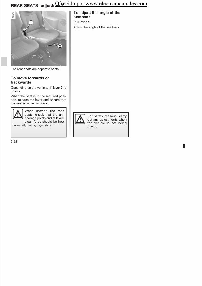
8/6/2019 NU773-8_ENG
http://slidepdf.com/reader/full/nu773-8eng 134/223
3.32
The rear seats are separate seats.
T mve frwards r
bacwardsDepending on the vehicle, lift lever 2 tounlock.
When the seat is in the required posi-tion, release the lever and ensure thatthe seat is locked in place.
When moving the rear seats, check that the an-
chorage points and rails areclean (they should be free
from grit, cloths, toys, etc.)
For safety reasons, carryout any adjustments whenthe vehicle is not beingdriven.
2
REAR SEATS: fnctins
Tension wheels 4 located under eachof the rear seats are used to keep theseats folded down.Unhook the tension wheel from ring 5 and hook it to the rods on the headrestin front.
T retrn te seats
Unhook retainer 4 from the headrest
rods, and stow it by hooking it into
2
1
4
Ofrecido por www.electromanuales.com

8/6/2019 NU773-8_ENG
http://slidepdf.com/reader/full/nu773-8eng 135/223
3.33
T fd dwn te rear seatsThe seats can be folded down in order to transport large objects:From the front, lower the headrest.From the rear, lift handle 2 to fold downthe seatback, lower bar 1 of the seatconcerned and move it forwards fully.Lift the controls 3 located either sideof the seat and lift the seat against thefront seats.
rods, and stow it by hooking it intoring 5 . Lower the seat until it is approxi-mately 10 cm from the floor then re-lease it. The seat positions itself under its own weight. Raise the seatback andensure the seat is correctly locked.
When moving the rear seats, ensure that nothing
obstructs the anchoragepoints (passenger’s arm or
leg, a pet, gravel, cloth, toys, etc.).
3 5
When tilting the seats, becareful not to lock the seatbelts. If this happens, tiltthe seat again. Pull the belt
strap, reposition the seat and re-lease the strap.
For safety reasons, carryout any adjustments whenthe vehicle is not beingdriven.
Wen refittin te seat-bac, make sure it is cor-rectly locked in place.If seat cvers are fitted,
make sure these do not prevent theseatback latch from locking in.Make sure that the seat belts arepositioned correctly.Reposition the headrests.
REAR BENCh SEAT: fnctins
Wen refittin te seat-bac make sure it is cor
When moving the rear seats, ensure that nothingobstructs the anchoragepoints (passenger’s arm or
leg, a pet, gravel, cloth, toys, etc.).4 4
A2
1
Ofrecido por www.electromanuales.com

8/6/2019 NU773-8_ENG
http://slidepdf.com/reader/full/nu773-8eng 136/223
3.34
The seat and the seatback may befolded away to allow large objects to betransported.
T raise te seatBefore handling the bench seat, ensurethe seat belt catches 1 are attachedto the corresponding buckles 2 andensure the front seats are far enoughforward.From the front, lift the seat base 3 against the front seats (movement A).
T fd awa te seat,proceed in reverse order.Position the rear bench seat cushion insuch a way so as to position the rear section of the seat base under the seat-back.Check that it is correctly locked in po-sition.
T fd dwn te seatbacFrom the luggage compartment, pullstraps 4 either side of the bench seat,and lower the seatback.
T raise te seatbac,proceed in reverse order.Refit the seatback and click it back intoplace.
For safety reasons, carryout any adjustments whenthe vehicle is not beingdriven.
When moving the benchseat, ensure that the seatbelt catches are correctlylocked in position.
When the bench seat has been putback in place, make sure that it iscorrectly locked and the seat beltsare correctly repositioned.
bac, make sure it is cor-rectly locked in place.If seat cvers are fitted,
make sure these do not prevent theseatback latch from locking in.Make sure that the seat belts arepositioned correctly.Reposition the headrests.
3
luggAgE CoMPARTMENT
2
Ofrecido por www.electromanuales.com

8/6/2019 NU773-8_ENG
http://slidepdf.com/reader/full/nu773-8eng 137/223
3.35
The tailgate is locked and unlocked atthe same time as the doors.
T penPress button 1 and lift the tailgate.
T cse
Pull down the tailgate using handle 2 inside the tailgate to assist you.
Once you have lowered the tailgate,release handle 2 and finish closing thetailgate by pressing down on the tail-gate from the outside.
1
REAR PARCEl ShElF (1/2)
11
263
4
3
5
Ofrecido por www.electromanuales.com

8/6/2019 NU773-8_ENG
http://slidepdf.com/reader/full/nu773-8eng 138/223
3.36
Versin wit benc seat
To remove, unhook the two straps 1.
Lift parcel shelf 2 .
To refit it, proceed in reverse order toremoval.
Versin wit seats
To remove (bulky loads):
– Unhook both straps 3;
– remove the pivots 4 from their hous-ing;
– unclip the parcel shelf 5 .
To refit:
– Clip the parcel shelf;
– ensure the straps pass behind thebar 6 as shown;
– hook both straps.
Do not place any objects,especially heavy or hardobjects, on the rear parcel
shelf. These may pose arisk to the vehicle occupants if thedriver has to brake suddenly or if thevehicle is involved in an accident.
63 3
REAR PARCEl ShElF (2/2)
78
Ofrecido por www.electromanuales.com

8/6/2019 NU773-8_ENG
http://slidepdf.com/reader/full/nu773-8eng 139/223
3.37
Rear seats mved bacf
When the seatbacks are re-clined 8 beyond area 7, it is
essential to remove the parcel shelf.
This prevents contact with the seator a passenger’s head when the tail-
gate is shut. The illustration abovewill remind you to take care.
Transprtin bjects
Objects loaded must not protrudebeyond area 7 (refer to the information
on “Transporting objects in the luggagecompartment” in Section 3).
If they do, it is essential to remove theparcel shelf.
luggAgE CoMPARTMENT CoVER: tiit versinsOfrecido por www.electromanuales.com
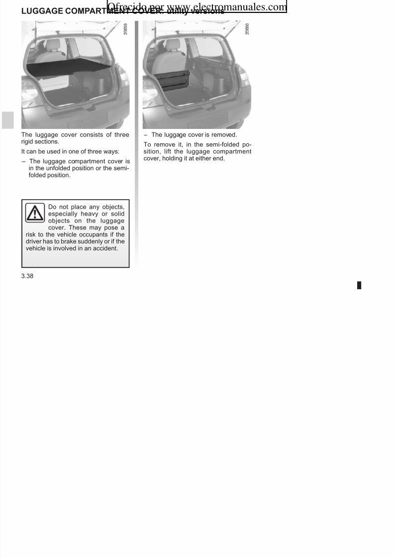
8/6/2019 NU773-8_ENG
http://slidepdf.com/reader/full/nu773-8eng 140/223
3.38
The luggage cover consists of threerigid sections.
It can be used in one of three ways:
– The luggage compartment cover isin the unfolded position or the semi-folded position.
– The luggage cover is removed.
To remove it, in the semi-folded po-sition, lift the luggage compartment
cover, holding it at either end.
Do not place any objects,especially heavy or solidobjects on the luggage
cover. These may pose arisk to the vehicle occupants if thedriver has to brake suddenly or if thevehicle is involved in an accident.
TRANSPoRTINg oBJECTS IN ThE luggAgE CoMPARTMENT
lcatins fr ancraepints
These are for securing items trans-ported in the luggage compart-ment (refer to the information on“Transporting objects in the luggagecompartment”).
A B
Ofrecido por www.electromanuales.com

8/6/2019 NU773-8_ENG
http://slidepdf.com/reader/full/nu773-8eng 141/223
3.39
Always place the objects to be trans-ported so that their largest side restsagainst the back of the rear benchseat, for normal loads (Example A), or
against the back of the front seats whenthe rear bench seatbacks are foldeddown, as with maximum loads (exam-ple B).
Always position the heavi-est items directly on thefloor. Use the lashing pointson the floor of the luggage
compartment, if these are fitted tothe vehicle. The luggage should beloaded in such a way that no itemswill be thrown forward and strike theoccupants if the driver has to brakesuddenly. Fasten the rear seat belts,even if the seats are not occupied.
RooF BARS
When fitting roof bars, at the front of thevehicle, replace the blanking bolts withthe mounting bolts supplied with theroof bars. Behind seal 3, position theroof bars in the reinforced area 4 pro-vided.
1 2 3 4
Ofrecido por www.electromanuales.com

8/6/2019 NU773-8_ENG
http://slidepdf.com/reader/full/nu773-8eng 142/223
3.40
Accessin te mntinpints
Open the doors. Behind seal 2 are
blanking bolts 1 which protect themounting bolt locations.
Never remove blankingbolts 1 without plugging theholes afterwards.
Once they are secured onto the vehicle, the mount-ing bolts should never beremoved (risk of damaging
the vehicle).
If original roof bars, approved by our Technical Department, are supplied
with screws, only use these screwsfor attaching the roof bars to the ve-hicle.
For information on the range of
equipment adapted to your vehi-cle, we advise you to consult an ap-proved Dealer.
Refer to the fitting instructions for in-formation on how to fit roof bars andconditions of use.
Please keep these instructions withthe rest of the vehicle documenta-tion.
Maximm permissibe ad nrf rac: refer to the informationon “Weights” in Section 6.
Section 4: MaintenanceOfrecido por www.electromanuales.com

8/6/2019 NU773-8_ENG
http://slidepdf.com/reader/full/nu773-8eng 143/223
4.1
Bonnet . . . . . . . . . . . . . . . . . . . . . . . . . . . . . . . . . . . . . . . . . . . . . . . . . . . . . . . . . . . . . . . . . . . . . . . . 4.2Engine oil levels: . . . . . . . . . . . . . . . . . . . . . . . . . . . . . . . . . . . . . . . . . . . . . . . . . . . . . . . . . . . . . . . . 4.4general information . . . . . . . . . . . . . . . . . . . . . . . . . . . . . . . . . . . . . . . . . . . . . . . . . . . . . . . . 4.4topping up/filling . . . . . . . . . . . . . . . . . . . . . . . . . . . . . . . . . . . . . . . . . . . . . . . . . . . . . . . . . . . 4.5
Engine oil change . . . . . . . . . . . . . . . . . . . . . . . . . . . . . . . . . . . . . . . . . . . . . . . . . . . . . . . . . . . . . . . 4.6Levels: . . . . . . . . . . . . . . . . . . . . . . . . . . . . . . . . . . . . . . . . . . . . . . . . . . . . . . . . . . . . . . . . . . . . . . . . 4.7
Brake fluid . . . . . . . . . . . . . . . . . . . . . . . . . . . . . . . . . . . . . . . . . . . . . . . . . . . . . . . . . . . . . . . 4.7Coolant . . . . . . . . . . . . . . . . . . . . . . . . . . . . . . . . . . . . . . . . . . . . . . . . . . . . . . . . . . . . . . . . . . 4.8windscreen washer reservoir . . . . . . . . . . . . . . . . . . . . . . . . . . . . . . . . . . . . . . . . . . . . . . . . . 4.9
Filters . . . . . . . . . . . . . . . . . . . . . . . . . . . . . . . . . . . . . . . . . . . . . . . . . . . . . . . . . . . . . . . . . . . . . . . . . 4.9Tyre pressure. . . . . . . . . . . . . . . . . . . . . . . . . . . . . . . . . . . . . . . . . . . . . . . . . . . . . . . . . . . . . . . . . . . 4.10Battery . . . . . . . . . . . . . . . . . . . . . . . . . . . . . . . . . . . . . . . . . . . . . . . . . . . . . . . . . . . . . . . . . . . . . . . . 4.11Bodywork maintenance . . . . . . . . . . . . . . . . . . . . . . . . . . . . . . . . . . . . . . . . . . . . . . . . . . . . . . . . . . . 4.12Interior trim maintenance . . . . . . . . . . . . . . . . . . . . . . . . . . . . . . . . . . . . . . . . . . . . . . . . . . . . . . . . . . 4.14
BONNET (1/2)
21
Ofrecido por www.electromanuales.com

8/6/2019 NU773-8_ENG
http://slidepdf.com/reader/full/nu773-8eng 144/223
4.2
To open the bonnet, pull handle 1. Unlocing te bonnet catc
To open, push tab 2 to the left as youopen the bonnet.
The engine may be hotwhen carrying out opera-
tions in close proximity. Inaddition, the engine cooling
fan can come on at any moment.
Risk of injury.
When working in the enginecompartment, ensure that
the windscreen wiper stalkis in the park position.
Risk of injury.
1
BONNET (2/2)
Closing te bonnetBefore closing the bonnet, check tomake sure that nothing has been left inthe engine compartment.
To close the bonnet, replace stay 4 inholder 5 . Hold the middle of the bonnetand guide it down to 20 cm above theclosed position, then release. It will latchautomatically under its own weight.
5
3
4
Ofrecido por www.electromanuales.com

8/6/2019 NU773-8_ENG
http://slidepdf.com/reader/full/nu773-8eng 145/223
4.3
Oening te bonnet
Lift the bonnet and release stay 4 fromits holder 5 . For your own safety, it is
ver imortant to fix the stay into re-tainer 3 in the bonnet.
In the event of even a slightimpact involving the radia-
tor grille or bonnet, havethe bonnet lock checked by
an approved dealer as soon as pos-sible.
Ensure that the bonnet isproperly locked.
Check that nothing is pre-venting the catch from lock-
ing (gravel, cloth, etc.).
Make sure nothing is left in theengine compartment (cloth, tools,
etc.).
It is normal for an engine to use oil for lubrication and cooling of moving partsand it is normal to top up the level be-tween oil changes.
However, contact an approved dealer if more than 0.5 litres is being consumedevery 600 miles (1,000 km) after therunning in period.
Oil cange frequenc: cec te oil
level from time to time and alwasbefore an long journe to avoid teris of damaging our engine
ENGINE OIL LEVEL: general information
Exceeding te maximumengine oil level
The oil level should only be read withthe dipstick as explained above.
If the oil level exceeds the maximumlevel, do not start our veicle and
contact an approved Dealer.
A
B
Ofrecido por www.electromanuales.com

8/6/2019 NU773-8_ENG
http://slidepdf.com/reader/full/nu773-8eng 146/223
4.4
ris of damaging our engine.
Consult an approved dealer at onceif you notice an abnormal or re-peated drop in any of the fluid levels.
In order to prevent splashing, it isrecommended that a funnel be usedwhen topping up/filling the oil.
Reading te level using tedistic – remove the dipstick (refer to the fol-
lowing pages for its location) andwipe it with a clean lint-free cloth;
– push in the dipstick as far as it willgo;
– take out the dipstick again; – read the level: it should never fall
below minimum mark A or exceedmaximum mark B.
Once the operation has been com-pleted, ensure that the dipstick is
pushed in as far as it will go or thatthe “cap-type dipstick” is completelyscrewed in.
Under no circumstances
should maximum fillinglevel B be exceeded: thiscould damage the engine
and the catalytic converter.
The engine may be hotwhen carrying out opera-
tions in close proximity. Inaddition, the engine cooling
fan can come on at any moment.
Risk of injury.
ENGINE OIL LEVEL: toing u/filling (1/2)
A1
2
1
2
1
2
Ofrecido por www.electromanuales.com

8/6/2019 NU773-8_ENG
http://slidepdf.com/reader/full/nu773-8eng 147/223
4.5
Secial features of 1.2 16VenginesTo unclip the dipstick, lever it by handwhile pressing engine cover A.
Toing u/fillingThe vehicle must be parked on levelground and the engine should be cold(for instance, before the engine isstarted up for the first time in the day).
– Unscrew cap1; – top up the level (as a guide, the ca-
pacity between the minimum andmaximum reading on dipstick 2 is
between 1.5 and 2 litres, dependingon the engine);
– wait for approximately 10 minutes toallow the oil to flow into the engine;
– check the level using dipstick 2 (asdescribed above).
Once the operation has been com-pleted, ensure that the dipstick ispushed in as far as it will go or that thecap-type dipstick is completely screwed
in.
Engine oil gradeRefer to the Maintenance ServiceBooklet for your vehicle.
Do not exceed the max level anddo not forget to refit cap 1 and dip-stick 2 .
1
2
Filling: take care whentopping up the oil thatno oil drips onto enginecomponents - risk of fire.
Remember to refit the cap securelyas there is a risk of fire if oil splashesonto hot engine components.
Oil cangeService interval: refer to theMaintenance Service Booklet for your vehicle.
Average caacities for oil cange (in-cluding oil filter for information).
1.2 16V engine: 4.35 litres1.2 TCE engine: 4.2 litres1.2 8V engine: 4.0 litres
1.5 dCi engine: 4.4 litres
E i il d
ENGINE OIL LEVEL: toing u/filling (2/2)ENGINE OIL ChANGEOfrecido por www.electromanuales.com

8/6/2019 NU773-8_ENG
http://slidepdf.com/reader/full/nu773-8eng 148/223
4.6
Never run the engine in anenclosed space as exhaust
gases are poisonous.
Consult your approved Dealer atonce if you notice an abnormal or repeated drop in any of the fluidlevels.
When working in the enginecompartment, ensure that
the windscreen wiper stalkis in the park position.
Risk of injury.
Engine oil grade
Refer to the Maintenance ServiceBooklet for your vehicle.
Engine oil cange: if you
are changing the oil whenthe engine is hot, be carefulnot to scald yourself if the
oil overflows.
The engine may be hotwhen carrying out opera-tions in close proximity. Inaddition, the engine cooling
fan can come on at any moment.
Risk of injury.
Toing uAfter any operation on the hydraulic cir-cuit, a specialist must replace the fluid.
Only use fluids approved by our Technical Department (and taken froma sealed container).
Relacement intervals:Refer to the Maintenance Service
Booklet for your vehicle.
LevelIt is normal for the level to drop as thebrake shoes become worn, but it mustnever drop lower than the “MIN” warn-ing line on the reservoir 1.
If you wish to check the disc and drumwear yourself, you should obtain thedocument explaining the checking pro-cedure from our network or from the
manufacturer’s web site.
LEVELS (1/3)
1
Ofrecido por www.electromanuales.com

8/6/2019 NU773-8_ENG
http://slidepdf.com/reader/full/nu773-8eng 149/223
4.7
Brae fluid
The level should be read with the engineswitched off and on level ground.
This should be checked frequently,and immediately if you notice even theslightest loss in braking efficiency.
When working in the enginecompartment, ensure that
the windscreen wiper stalkis in the park position.
Risk of injury.
The engine may be hotwhen carrying out opera-
tions in close proximity. Inaddition, the engine cooling
fan can come on at any moment.
Risk of injury.
LEVELS (2/3)
Relacement intervalsRefer to the Maintenance ServiceBooklet for your vehicle.
Cecing intervalsCec te coolant level regularl (very severe damage is likely to becaused to the engine if it runs out of coolant).
If the level needs to be topped up, onlyuse products approved by our TechnicalDepartment which ensure:
– protection against freezing;
– anticorrosion protection of the cool-ing system.
2
Ofrecido por www.electromanuales.com

8/6/2019 NU773-8_ENG
http://slidepdf.com/reader/full/nu773-8eng 150/223
4.8
Coolant
With the engine switched off and onlevel ground, the level wen cold must be between the “MIN” and “MAX”marks on reservoir 2 .
Top this level up wen cold before the“MIN” mark is reached.
No operations should becarried out on the cooling
circuit when the engine ishot.
Ris of burns.
When working in the enginecompartment, ensure that
the windscreen wiper stalkis in the park position.
Risk of injury.
Consult your approved dealer atonce if you notice an abnormal or repeated drop in any of the fluidlevels.
JetsTo adjust the angle of the jets, pivot thelittle ball using a pin.
LEVELS (3/3) /FILTERS
FiltersThe replacement of filter elements (air filter, passenger compartment filter,diesel filter, etc.) is scheduled in themaintenance operations for your vehi-cle.
Relacement intervals for filter ele-ments: refer to the maintenance docu-ment for your vehicle.
3
Ofrecido por www.electromanuales.com

8/6/2019 NU773-8_ENG
http://slidepdf.com/reader/full/nu773-8eng 151/223
4.9
Windscreen waser reservoir
FillingWith the engine switched off, open
cap 3 , fill until you can see the fluid,then refit the cap.
FluidWater + special windscreen washer fluid (antifreeze product in winter).
When working in the enginecompartment, ensure that
the windscreen wiper stalkis in the park position.
Risk of injury.
Consult an approved Dealer at onceif you notice an abnormal drop inany of the fluid levels.
NOTE
Depending on the vehicle, to findout the fluid level, open cap 3 andpull out the dipstick.
The engine may be hotwhen carrying out opera-
tions in close proximity. Inaddition, the engine coolingfan can come on at any moment.
Risk of injury.
TyRE pRESSURE
Tre safet and use of snowcains
Refer to the information on “Tyres”in Section 5 for the servicing con-ditions and, depending on the ver-
sion, the use of chains.Secial note
C D
FEG
A
h
A
B
Ofrecido por www.electromanuales.com

8/6/2019 NU773-8_ENG
http://slidepdf.com/reader/full/nu773-8eng 152/223
4.10
The tyre pressure is indicated onlabel A affixed to the edge of the driv-er’s door. Open the door to read it.
B: dimension of the tyres fitted to the
vehicle.
C : tyre pressures for the front wheels(non-motorway).
D: tyre pressures for the rear wheels(non-motorway).
E : tyre pressures for the front wheels(motorway).
F : tyre pressures for the rear wheels(motorway).
G : tyre pressure for the emergencyspare wheel.
H : dimensions of the emergency sparewheel tyre.
For veicles used full laden (maximum permissible all-upweight) and towing a trailer. Themaximum speed must be limitedto 60 m (100 m/) and the tyrepressure increased by 0.2 bar.
Refer to the information on “Weights”
in Section 6.
When they need to be replaced, only tyres of the same make, size, typeand profile should be used.
Tres fitted to te veicle sould eiter be identical to tose fittedoriginall or conform to tose recommended b our aroved
dealer.
BATTERy
1
A
B
2 3 4
567
Ofrecido por www.electromanuales.com

8/6/2019 NU773-8_ENG
http://slidepdf.com/reader/full/nu773-8eng 153/223
4.11
Batter
Depending on the vehicle, this is lo-cated underneath cover 1.
Batter access:
Depending on the vehicle, unclipcover A.
Relacing te batter
As this operation is complex, we adviseyou to contact an approved Dealer.
Take care when working inthe engine compartment
as the engine cooling fanmay start to operate at anymoment without warning.
Risk of injury.
When working in the enginecompartment, ensure that
the windscreen wiper stalkis in the park position.
Risk of injury.
Label B
Observe the indications on the battery: – 2 naked flames and smoking forbid-
den;
– 3 eye protection required; – 4 keep children at a safe distance; – 5 explosive materials; – 6 refer to the handbook; – 7 corrosive materials.
Handle the battery with careas it contains sulphuric acid,which must not come intocontact with eyes or skin. If
it does, wash the affected area withplenty of cold water. If necessary,consult a doctor.
Ensure that naked flames, red hotobjects and sparks do not come into
contact with the battery as there is arisk of explosion.
A well-maintained vehicle will last for longer. It is therefore recommended toregularly maintain the vehicle exterior.
protection against te effectsof corrosive agents
Although your vehicle has been treatedwith very effective anti-corrosion prod-ucts, it nevertheless remains subject to
the effects of: – corrosives in te atmosere
atmospheric pollution (urban and
You should take a minimum number of precautions in order to safeguard your vehicle against such risks and not tolose the benefit of your vehicle’s anti-corrosion protection.
Wat ou sould not do
– Wash the vehicle in bright sunlight or freezing temperatures.
– Scrape off mud or dirt withoutprewetting.
All di t t l t
– Degrease or clean mechanical com-ponents (e.g. engine compartment),underneath the body, parts withhinges (e.g. fuel filler cap, inside of filler flap, sunroof, etc.) and paintedexternal plastic fittings (e.g. bump-ers) using high-pressure clean-ing equipment or using spray prod-ucts not approved by our TechnicalDepartment. If adequate precautions
are not taken, this could give rise tocorrosion or operational faults.
BODyWORk MAINTENANCE (1/2)Ofrecido por www.electromanuales.com

8/6/2019 NU773-8_ENG
http://slidepdf.com/reader/full/nu773-8eng 154/223
4.12
– atmospheric pollution (urban andindustrial areas);
– saline atmosphere (near the sea,particularly in hot weather);
– seasonal and damp climatic con-ditions, (e.g.: road salt in winter,water from road cleaners, etc.).
– abrasives
wind-borne dust and sand, mud,road grit thrown up by other vehi-cles, etc.
– minor imacts.
– Allow dirt to accumulate.
– Allow rust to form following minor im-pacts.
– Use solvents not approved by our Technical Department to removestains as this could damage thepaintwork.
– Drive frequently in snow or muddyconditions without washing the ve-hicle, particularly under the wheelarches and body.
– Before going through a roller typecar wash, return the windscreenwiper stalk to park position (refer toSection 1: “Windscreen wash/wipe”).Check the mounting of external ac-cessories, additional lights and mir-rors, and ensure that the wiper blades are secured with adhesivetape.
Remove the radio aerial mast if your
vehicle is fitted with this equipment.
Remember to remove the tape andrefit the antenna after washing
BODyWORk MAINTENANCE (2/2)
Wat ou sould do – Wash your vehicle frequently, with
the engine off, using cleaning prod-ucts recommended by us (never useabrasive products), taking specialcare to rinse off: – spots of tree resin and industrial
grime; – bird droings, which contain
chemicals that raidl discolour
aintwor and ma even causete aint to eel off ;Wash the vehicle immediatel to
– Observe the vehicle stopping dis-tances when driving on gravelledsurfaces to prevent paint damage.
– Repair, or have repaired quickly,areas where the paint has beendamaged, to prevent corrosionspreading.
– Remember to visit the body shopperiodically if your vehicle has an
anti-corrosion warranty. Refer to theMaintenance Service Booklet for your vehicle.
Ofrecido por www.electromanuales.com

8/6/2019 NU773-8_ENG
http://slidepdf.com/reader/full/nu773-8eng 155/223
4.13
refit the antenna after washing.
– Spray mechanical components,hinges, etc. with products approvedby our Technical Department toprotect them after they have beencleaned.
Wash the vehicle immediatel toremove these marks since it is im-possible to remove them by pol-ishing;
– salt deposited in the wheel archesand the underneath the body after driving in areas where the roadshave been gritted;
– mud in the wheel arches and un-derneath the body which formsdamp patches.
– Respect local regulations aboutwashing vehicles (e.g. do not washyour vehicle on a public highway).
We have selected special productsto care for your vehicle and you canobtain these from the manufactur-er’s accessory outlets.
INTERIOR TRIM MAINTENANCE (1/2)
A well-maintained vehicle will have alonger service life. It is therefore ad-visable to maintain the vehicle interior regularly.
Stains should always be dealt withquickly. Whatever type of stain is onthe trim, use soa water (if possible,warm water) containing:
Do not use detergents (wasing uliquid, owdered roducts, alcool-based roducts, etc.).
Use a soft cloth.
Seat beltsThese must be kept clean.
Use products selected by our TechnicalDepartment (Approved outlets) or warm, soapy water and a sponge andwipe with a dry cloth.
Detergents or des must not be usedunder an circumstances.
Fabrics (seats, door trim,etc.)
Secial note regarding sweets andcewing gum: place an ice cube onthe stain to crystallise it, then cleanusing the procedure for a solid stain.
Ofrecido por www.electromanuales.com
8/6/2019 NU773-8_ENG
http://slidepdf.com/reader/full/nu773-8eng 156/223
4.14
Glass instrument anel(e.g.: instrument panel, clock, exterior temperature display, radio display).
Use a soft cloth or cotton wool.
If this does not clean it properly, use asoft cloth (or cotton wool) slightly mois-tened with soapy water and then wipeclean with a soft damp cloth or cottonwool.
Finally, carefull dry off with a soft drycloth.
Cleaning roducts containing alco-ol must not be used under an cir-cumstances.
Dust fabrics regularl.
Liquid stains
Use soapy water. Absorb or dab lightly(never rub) using a soft cloth, then rinseand absorb the excess water.
Solid or tic stainsRemove any excess solid or thick ma-terial immediatel and carefully usinga spatula (from the edge inwards toavoid spreading the stain).
Clean using the procedure for a liquidstain.
INTERIOR TRIM MAINTENANCE (2/2)
Removing/refitting factorfitted removable equimentin te veicle
If you need to remove equipment toclean the passenger compartment (e.g.mats), always make you refit it properlyand on the correct side (driver’s sidemats must be fitted on the driver’s side,etc.), using retaining components sup-
plied with the equipment (e.g. the driv-er’s side mat must always be securedusing prefitted retaining devices).
Wat ou sould not doYou are strongly advised not to placeitems such as air fresheners, perfumeetc. near the air vents as these coulddamage the dashboard fittings.
Ofrecido por www.electromanuales.com

8/6/2019 NU773-8_ENG
http://slidepdf.com/reader/full/nu773-8eng 157/223
4.15
In all cases, with the vehicle stationary,ensure that nothing can hinder driving(obstacle underneath the pedals, heeltrapped by the mat, etc.).
You are strongly recom-mended not to use high-pressure or spray cleaningequipment inside the pas-
senger compartment: this equip-ment could impair the correct func-tioning of the electrical or electroniccomponents in the vehicle, or haveother detrimental effects.
Ofrecido por www.electromanuales.com

8/6/2019 NU773-8_ENG
http://slidepdf.com/reader/full/nu773-8eng 158/223
4.16
Section 5: Practical advice
Puncture 5 2
Ofrecido por www.electromanuales.com

8/6/2019 NU773-8_ENG
http://slidepdf.com/reader/full/nu773-8eng 159/223
5.1
Puncture . . . . . . . . . . . . . . . . . . . . . . . . . . . . . . . . . . . . . . . . . . . . . . . . . . . . . . . . . . . . . . . . . . . . . . 5.2Tyre inflation kit . . . . . . . . . . . . . . . . . . . . . . . . . . . . . . . . . . . . . . . . . . . . . . . . . . . . . . . . . . . . . . . . . 5.3Tool kit . . . . . . . . . . . . . . . . . . . . . . . . . . . . . . . . . . . . . . . . . . . . . . . . . . . . . . . . . . . . . . . . . . . . . . . . 5.6Wheel trims - Wheels . . . . . . . . . . . . . . . . . . . . . . . . . . . . . . . . . . . . . . . . . . . . . . . . . . . . . . . . . . . . 5.7Changing a wheel . . . . . . . . . . . . . . . . . . . . . . . . . . . . . . . . . . . . . . . . . . . . . . . . . . . . . . . . . . . . . . . 5.8Tyres (tyre and wheel safety, use in winter) . . . . . . . . . . . . . . . . . . . . . . . . . . . . . . . . . . . . . . . . . . . 5.10
Wiper blades . . . . . . . . . . . . . . . . . . . . . . . . . . . . . . . . . . . . . . . . . . . . . . . . . . . . . . . . . . . . . . . . . . . 5.13Changing bulbs . . . . . . . . . . . . . . . . . . . . . . . . . . . . . . . . . . . . . . . . . . . . . . . . . . . . . . . . . . . . . . . . . 5.14
Headlights . . . . . . . . . . . . . . . . . . . . . . . . . . . . . . . . . . . . . . . . . . . . . . . . . . . . . . . . . . . . . . . 5.14Rear lights . . . . . . . . . . . . . . . . . . . . . . . . . . . . . . . . . . . . . . . . . . . . . . . . . . . . . . . . . . . . . . . 5.17Indicator lights . . . . . . . . . . . . . . . . . . . . . . . . . . . . . . . . . . . . . . . . . . . . . . . . . . . . . . . . . . . . 5.20Interior lighting . . . . . . . . . . . . . . . . . . . . . . . . . . . . . . . . . . . . . . . . . . . . . . . . . . . . . . . . . . . . 5.21
Battery: troubleshooting. . . . . . . . . . . . . . . . . . . . . . . . . . . . . . . . . . . . . . . . . . . . . . . . . . . . . . . . . . . 5.23Radio frequency remote control: batteries. . . . . . . . . . . . . . . . . . . . . . . . . . . . . . . . . . . . . . . . . . . . . 5.25
Fuses . . . . . . . . . . . . . . . . . . . . . . . . . . . . . . . . . . . . . . . . . . . . . . . . . . . . . . . . . . . . . . . . . . . . . . . . . 5.26Towing (breakdown - attachments) . . . . . . . . . . . . . . . . . . . . . . . . . . . . . . . . . . . . . . . . . . . . . . . . . . 5.29Fitting a radio/accessories . . . . . . . . . . . . . . . . . . . . . . . . . . . . . . . . . . . . . . . . . . . . . . . . . . . . . . . . . 5.32Accessories . . . . . . . . . . . . . . . . . . . . . . . . . . . . . . . . . . . . . . . . . . . . . . . . . . . . . . . . . . . . . . . . . . . . 5.34Operating faults . . . . . . . . . . . . . . . . . . . . . . . . . . . . . . . . . . . . . . . . . . . . . . . . . . . . . . . . . . . . . . . . . 5.35
Puncture
1
2
4
3
A
Vhils fid wih amy spa whlsmall ha h fo oh whls:
– Never fit more than one emer-gency spare wheel to the samevehicle.
– Replace the emergency sparewheel as soon as possible with awheel with the same dimensionsas the original
Ofrecido por www.electromanuales.com

8/6/2019 NU773-8_ENG
http://slidepdf.com/reader/full/nu773-8eng 160/223
5.2
I h v of a p,dpdi o h vhil,yo will hav:
An emergency spare wheel or tyre in-flation kit (refer to the information on thefollowing pages).
emy spa whl 2
This is located in the luggage compart-ment. To access it:
– open the tailgate;
– lift the luggage compartment carpet1 (or depending on vehicle, hook it to
the bench seatback);
– remove the jack from its storagespace A;
– unscrew the central mounting 4;
– remove the tool kit3 lifting it fromboth sides;
– remove emergency spare wheel 2 .
If the emergency sparewheel has been storedfor several years, have itchecked by your Dealer to
ensure that it is safe to use.
as the original.
– When this is fitted to the vehicle,which must only be a temporarymeasure, the driving speed mustnot exceed the speed indicatedon the label on the wheel.
– Fitting an emergency sparewheel may alter the way the ve-hicle usually runs. Avoid suddenacceleration or deceleration andreduce your speed when corner-ing.
– If you need to use snow chains,fit the emergency spare wheel tothe rear axle and check the tyrepressure.
tYre InFLAtIOn KIt (1/3)
Do not attempt to use theinflation kit if the tyre hasbeen damaged as a resultof driving with a puncture.
You should therefore carefully checkthe condition of the tyre sidewallsbefore any operation.
Driving with underinflated, flat or punctured tyres can be dangerous
and may make the tyre impossibleto repair.
this pai is mpoay
The kit is only approved for inflating the tyres of the ve-hicle originally equippedwith the kit.
It must never be used to inflatethe tyres of another vehicle, or anyother inflatable object (rubber ring,rubber boat, etc.).
Avoid spillage on skin when han-
dling the repair liquid bottle. If drop-lets do leak out, rinse them off withplenty of water.
A B
Ofrecido por www.electromanuales.com

8/6/2019 NU773-8_ENG
http://slidepdf.com/reader/full/nu773-8eng 161/223
5.3
p p y
A tyre which has been puncturedshould always be inspected (andrepaired, where possible) by a spe-cialist.
When taking a tyre which has beenrepaired using this kit to be replaced,you must inform the specialist.
When driving, vibration may be feltdue to the presence of the repair product injected into the tyre.
Keep the repair kit away from chil-dren.
Do not dispose of the empty bottlein the countryside. Return it to your approved dealer or to a recycling or-ganisation.
The bottle has a limited servicelife which is indicated on its label.Check the expiry date.
Contact an approved dealer to re-place the inflation tube and repair product bottle.
The kit repairs tyres whentread A has been dam-aged by objects smaller than 4 mm. It cannot repair
all types of puncture, such as cutslarger than 4 mm, or cuts in tyresidewall B.
Ensure also that the wheel rim is ingood condition.
tYre InFLAtIOn KIt (2/3)
– Take the compressor 4 and thebottle 1 located under the luggagecompartment carpet;
– unroll the inflation hose8 and thelead 9 located under the compressor and the inflation hose 10 . Attach thebottle to its mounting 3 and screwthe inflation hose 8 onto the endpiece 2 ;
– unscrew the valve cap of the wheelconcerned and screw the inflationhose 10 onto the valve;
– with the ignition on, connect the end
If h ommdd pss aob ahivd, pai is impossibl. Doo div h vhil. cosl a ap-povd dal.
Once the tyre is correctly inflated,remove the kit: slowly unscrew the twoinflation end pieces 8 and 10 and screwthe end piece 10 to the bottle to ensureno product escapes.10
1
2 4 5 6
7
8
9
3
Ofrecido por www.electromanuales.com

8/6/2019 NU773-8_ENG
http://slidepdf.com/reader/full/nu773-8eng 162/223
5.4
Depending on the vehicle, in the eventof a puncture, use the tyre inflation kit.
with the ignition on, connect the endpiece 8 to one of the vehicle’s ac-cessories sockets (refer to the para-graph “Accessories socket” in chap-ter 3) then press the switch 7 toinflate the tyre to the recommendedpressure (refer to the label located
on the edge of the driver’s door); – After a maximum of 7 minutes, stop
inflating and read the pressure onpressure gauge 6 . To adjust thepressure if necessary: continue in-flating to increase the pressure or press button 5 to decrease it.
Before using this kit, parkthe vehicle at a sufficientdistance from traffic, switchon the hazard warning
lights, apply the handbrake, ask allpassengers to leave the vehicle andkeep them away from traffic.
Do not pull out the foreign bodycausing the puncture if it is still in
the tyre.
If the vehicle is parked onthe hard shoulder, you mustwarn other road users of your vehicle’s presence
with a warning triangle or with other devices as per the legislation apply-ing to the country you are in.
tYre InFLAtIOn KIt (3/3)
Start immediately and drive between1.8 and 6 miles (3 and 10 km) (10 min-utes driving) then stop to check thepressure. If it is above 1.3 ba , adjustit to the recommended pressure (refer to the label located on the edge of thedriver’s door), otherwise contact an ap-proved dealer: repair is not possible.
Paios wh si hki
The kit should not be operated for morethan 15 consecutive minutes.
1
Ofrecido por www.electromanuales.com

8/6/2019 NU773-8_ENG
http://slidepdf.com/reader/full/nu773-8eng 163/223
5.5
Affix the driving recommendation label,located on bottle 1, to the dashboardwhere it can easily be seen by thedriver.
Put the kit away.
Following repair with the kit,do not travel further than120 miles (200 km). In addi-tion, reduce your speed and
under no circumstances exceed 48mph (80 km/h). The sticker, whichyou must affix in a prominent posi-tion on the dashboard, reminds youof this.
Depending on the country or locallegislation, a tyre repaired with theinflation kit may need to be replaced.
Nothing should be placedaround the driver’s feetas such objects may slideunder the pedals during
sudden braking manoeuvres andobstruct their use.
Please be aware that apoorly tightened or miss-ing valve cap can make thetyres less airtight and lead
to pressure loss.
Always use valve caps identical to
those fitted originally and tightenthem fully.
Hbap ool5
o 6
This tool is used to remove the wheeltrims.
Jak 3
Remove jack 3 .
When replacing the jack, fold it cor-rectly and position the wheelbrace cor-rectly before replacing it in its position.
tOOL KIt
13
2
3
4
5
6
7
Ofrecido por www.electromanuales.com

8/6/2019 NU773-8_ENG
http://slidepdf.com/reader/full/nu773-8eng 164/223
5.6
Tool kit 3 is located in the emergencyspare wheel. It consists of a set of toolsfor various operations on the vehicle: a jack and wheelbrace, towing hitch, etc.,and a space for a spare bulb box.
The tools included in the tool kit dependon the vehicle.
Soa ompams 1
This is for storing a box of bulbs.
Soa ompams 2
This is for storing four wheel bolts.
Whlba4
This is used to tighten or release thewheel bolts.
towi hih 7
Refer to the information on “Towing” inSection 5.
Do not leave the tools un-secured inside the vehicleas they may come looseunder braking. After use,
check that all the tools are correctlyclipped into the tool kit, then positionit correctly in its housing: there is arisk of injury.
The jack is designed for wheelchanging purposes only. It shouldnever be used for repairs or gainingaccess to the underneath of the ve-
hicle.
6
WHeeL trIM - WHeeLS
1
3
2
A
c
D
B
4
5
6
Ofrecido por www.electromanuales.com

8/6/2019 NU773-8_ENG
http://slidepdf.com/reader/full/nu773-8eng 165/223
5.7
Whl im (xampl: whlim 1)
Remove the wheel trim using hubcaptool 3 (stored in the tool kit) by engag-
ing the hook in the opening for valve 2 .
To refit it, align it with valve 2 .
Push the retaining hooks in fully, start-ing on the side of valve A, followedby B and D, finishing at C opposite thevalve.
cal whl im (xampl:whl im 4)
Remove the wheel trim using hubcaptool 5 (located in the tool kit) inserting
the tool into recess 6 .
To refit it, position it in line with recess 6 and tighten it with tool 5 .
We would advise you to note thenumber engraved on the tool so thatyou can replace it if it is lost.
2
Start extending jack 2 by hand, turningthe handle. Position the head correctlyunder vertical sill seam 3 nearest to thewheel concerned and marked by anoblong hole.
Continue turning the handle to positionthe baseplate of the jack on the groundcorrectly.
Turn a few times to lift the wheel off theground, remove the bolts and take off
the wheel.
cHAngIng A WHeeL (1/2)
1
3
2
Ofrecido por www.electromanuales.com

8/6/2019 NU773-8_ENG
http://slidepdf.com/reader/full/nu773-8eng 166/223
5.8
Vhils qippd wih a jakad whlba
If necessary, remove the wheel trim.
Use the wheelbrace to slacken off thewheel bolts 1. Fit it so that you pressdownwards rather than pulling up-wards.
Switch on the hazard warn-ing lights.
Keep the vehicle away from
traffic and on a level sur-face where it will not slip (if neces-sary, place a solid support under the jack base).
Apply the handbrake and engage agear (first or reverse).
Ask all the passengers to leave thevehicle and keep them away fromtraffic.
To prevent any risk of injuryor damage to the vehicle,only crank the jack until thewheel you are replacing is
a maximum of 3 centimetres off theground.
If the vehicle is not equipped with a jack or wheelbrace, you can obtainthese from your approved dealer.
Fit the emergency spare wheel on thecentral hub and turn it to locate themounting holes in the wheel and thehub.
If bolts are supplied with the emergencyspare wheel, only use these bolts for the emergency spare wheel. Tightenthe bolts, checking that the wheel iscorrectly positioned on its hub and un-screw the jack.
With the wheel on the ground, tightenthe bolts fully and have the tightnessof the bolts checked (tightening torque:110 Nm) and the emergency spare
cHAngIng A WHeeL (2/2)Ofrecido por www.electromanuales.com

8/6/2019 NU773-8_ENG
http://slidepdf.com/reader/full/nu773-8eng 167/223
5.9
Ai-hf bols
If you use anti-theft bolts, fit thesenearest the valve (otherwise it maynot be possible to fit the wheel trim).
If the vehicle is parked onthe hard shoulder, you mustwarn other road users of your vehicle’s presence
with a warning triangle or with other devices as per the legislation apply-ing to the country you are in.
If you have a puncture, re-place the wheel as soon aspossible.
A tyre which has been punc-tured should always be inspected(and repaired, where possible) by aspecialist.
110 Nm) and the emergency sparewheel pressure checked as soon aspossible.
tYreS (1/3)
ty ad whl safy
The tyres are the only contact betweenthe vehicle and the road, so it is essen-tial to keep them in good condition.
You must make sure that your tyresconform to local road traffic regulations.
When the tyre tread has been worn
to the level of the warning strips, hybom visibl 2 : it is h neces-sary to replace your tyres because thetread rubber is now only 1.6 mm dpa mos, sli i poo oad hold-i o w oads.
An overloaded vehicle, long journeysby motorway, particularly in very hotweather, or continual driving on poorly
surfaced minor roads will lead to morerapid tyre wear and affect safety.
1
2
Ofrecido por www.electromanuales.com

8/6/2019 NU773-8_ENG
http://slidepdf.com/reader/full/nu773-8eng 168/223
5.10
Maiaii h ys
The tyres must be in good conditionand the tread form must have sufficientdepth; tyres approved by our techni-
cal department have tread wear indica-tors 1 which are idiaos molddio h ad a sval pois.When they need to be re-
placed, only tyres of thesame make, size, type andprofile should be used.
tys fid o h vhil sholdih b idial o hos fidoiially o ofom o hosommdd by yo appovd
dal.
Incidents which occur whendriving, such as striking thekerb, may damage the tyresand wheel rims, and could
also lead to misalignment of thefront or rear axle geometry. In thiscase, have the condition of thesechecked by an approved dealer.
tYreS (2/3)
ty psss
Tyre pressures must be adhered to (in-cluding the emergency spare wheel).Pressures must be checked at leastonce a month and always before along journey (refer to the information on“Tyre pressures”).
Pressures should be checked when the
tyres are cold; ignore higher pressureswhich may be reached in hot weather or following a fast journey.
If tyre pressures cannot be checkedwhen the tyres are old, the normalpressures must be increased by 0.2 to0.3 bar (or 3 PSI).
nv dfla a ho y.
no: a label (depending on country or model) fixed to the edge or frame of thedriver’s door gives the recommendedtyre pressures.
Fii w ys
For safety reasons, this op-eration must be carried outby a specialist.
Fitting different tyres maychange your vehicle as follows: – it may mean that your vehicle no
longer conforms to current regu-
lations; – it may change the way it handles
when cornering; – it may cause the steering to beIo y psss
Ofrecido por www.electromanuales.com

8/6/2019 NU773-8_ENG
http://slidepdf.com/reader/full/nu773-8eng 169/223
5.11
chai whls aodThis practice is not recommended.
emy spa whl
Refer to the information on the“Emergency spare wheel” and in-structions on “Changing a wheel” inSection 5.
y gheavy;
– it may affect the use of snowchains.
Please be aware that amissing valve cap canmake the tyres less airtightand lead to pressure loss.
Always use valve caps identical tothose fitted originally and tightenthem fully.
lead to abnormal tyre wear and unusually hot running.These are factors which
may seriously affect safety and leadto: – poor road holding;
– the risk of blow-outs or of throw-ing a tread.
Tyre pressures depend on the loadand the driving speed. Adjust thepressures according to the condi-tions of use. (Refer to the informa-tion on “Tyre pressures”).
tYreS (3/3)
– Sow o wi ys
We would recommend that these befitted to all fo whls to ensurethat your vehicle retains maximumadhesion.
no: we would point out that thesetyres may sometimes have:
– a specific direction of rotation
– a maximum speed index which
may be lower than the maximumspeed of your vehicle.
– Sddd ys
Thi t f i t l b
us i wi
– chais
Fo safy asos, fii sowhais o h a axl is silyfobidd.
chais ms o b fid to tyreswhich are larger than those originallyfitted to the vehicle.
Ofrecido por www.electromanuales.com

8/6/2019 NU773-8_ENG
http://slidepdf.com/reader/full/nu773-8eng 170/223
5.12
This type of equipment may only beused for a limited period and as laiddown by local legislation.
It is necessary to observe the speedspecified by current legislation.
These tyres must, at a minimum, befitted to the two front wheels.
Chains may only be fitted
to tyres of the same sizeas those originally fitted toyo vhil.
In all cases, we would recommend
that you contact an approved Dealer who will be able to advise you onthe choice of equipment which ismost suitable for your vehicle.
WInDScreen WIPer BLADeS
rplai a s wip blad 6 – Lift wiper arm 5 ; – pivot the blade until some resistance
is met; – remove the blade by pulling it.
rfii a fo o a wip bladTo refit the wiper blade, proceed in re-verse order to removal.Make sure that the blade is correctlylocked in position.
3
1
2
4
5
6
Ofrecido por www.electromanuales.com

8/6/2019 NU773-8_ENG
http://slidepdf.com/reader/full/nu773-8eng 171/223
5.13
rplai wids wip blads 1 – Lift the windscreen wiper arm 3 as
far as it will go (the arm does not lift
up completely);
– press button2 and slide the wiper blade sideways to release hook 4 onthe wiper arm.
Before using the wipers, check that no objects are obstructing the travelof the blades.
– In frosty weather, make sure that the wiper blades are not stuck by ice(to avoid the risk of the motor overheating).
– Check the condition of the wiper blades. Replace the wiper blades as soon asthey begin to lose efficiency (approximately once a year).
Whilst changing the blade, take care not to drop the arm onto the window after ithas been removed as this may break the window.
Check the condition of the wiper blades. You are responsible for their service life: – clean the blades, windscreen and
rear screen regularly with soapywater;
– do not use them when the wind-screen or rear screen are dry;
– free them from the windscreen or rear screen when they have notbeen used for a long time.
clai h hadlihs
As the headlights are made of plasticglass, use a soft cloth or cotton wool toclean them.
If this does not clean them properly,use a soft cloth (or cotton wool) slightlymoistened with soapy water and thenwipe clean with a soft damp cloth or cotton wool.
Finally, dry off aflly with a soft drycloth.
clai pods oaii alo-hol ms o b sd d ay i-
To comply with local legislation, or as
a precaution, you can obtain an emer-gency kit containing a set of spare bulbsand fuses from your approved dealer.
Fo vhils wih limid ass oblbs ha may qi ai bod-ywok o mhaial omposo b movd: contact an approveddealer.
HeADLIgHtS: hai blbs (1/3)Ofrecido por www.electromanuales.com

8/6/2019 NU773-8_ENG
http://slidepdf.com/reader/full/nu773-8eng 172/223
5.14
msas.
The bulbs are under pres-sure and can break whenreplaced.
Risk of injury.
As h hadlihs afid wih plasi lass,i is ssial o s ai-uV blbs (using any other
type of bulb could lead to headlightdamage).
HeADLIgHtS: hai blbs (2/3)
Fo sid lih
– Unclip cover A and remove it;
– remove bulb holder 4 from its hous-ing without pulling on the cable;
– change the bulb.
Blb yp: W5W.
Diio idiao lihs
Rotate bulb holder 1 a quarter of a turn.Change the bulb.
Blb yp: PY21W.
A
1
6
32
4
5
3
Ofrecido por www.electromanuales.com

8/6/2019 NU773-8_ENG
http://slidepdf.com/reader/full/nu773-8eng 173/223
5.15
– Unclip cover A and remove it; – disconnect bulb 2 and remove the
springs 6 ; – remove the lamp from the connector.
typ of halo blb: H4 60/55 WDo o oh h blb lass. Hold iby is bas.During fitting, note the correct fitting of the tabs 3 .
Mai bam/dippd hadlihs
Note the correct positioning of the har-nesses 5 before removal in order to po-sition them correctly when refitting.
To return it, proceed in the reverseorder to removal.It is recommended that the headlightsbe adjusted after this operation.
For refitting, ensure the bulb holder iscorrectly locked.
The bulbs are under pres-sure and can break whenreplaced.
Risk of injury.
The engine may be hotduring operations in closeproximity. In addition, the
engine cooling fan maystart at any moment.
Risk of injury.
Addiioal lihs
If you wish to fit fog lights or long rangeheadlights to your vehicle, consult anapproved dealer.
HeADLIgHtS: hai blbs (3/3)
7
8
Ofrecido por www.electromanuales.com

8/6/2019 NU773-8_ENG
http://slidepdf.com/reader/full/nu773-8eng 174/223
5.16
Fo fo lihs 7
chai a blb
– Depending on the vehicle, unclip
the cover and remove it (Torx bit no.120);
– turn bulb8 a quarter of a turn andremove it;
– disconnect the bulb and change it.
Blb yp: H11 55W.
For refitting, proceed in the reverseorder to removal.
Ensure the bulb is correctly locked inposition. Depending on the vehicle,
reposition the cover.Spial fas of 1.2 tce vsios: due to reduced accessibility, certaincomponents may need to be removedoccasionally (front bumper, etc.). Weadvise you to have the bulb replacedby an approved dealer.
The bulbs are under pres-sure and can break whenreplaced.
Risk of injury.
Any operation on (or modi-fication to) the electricalsystem must be performedby an approved dealer
since incorrect connections coulddamage the electrical equipment(wiring, components, in particu-lar the alternator). In addition, your dealer has available all the partsnecessary for fitting electrical com-ponents.
reAr LIgHtS: hai blbs
12
3
4
5
Ofrecido por www.electromanuales.com

8/6/2019 NU773-8_ENG
http://slidepdf.com/reader/full/nu773-8eng 175/223
5.17
Remove bolt 1 using the appropriatetool and remove the rear light unit fromthe outside.
Unclip the bulb holder using tabs 2 . 3 Sid lihs ad bak lihsPear shaped, bayonet type P 21/5 V bulb with two filaments.
4 Idiao
Orange pear-shaped, bayonet typePY 21 W bulb.
5 Fo lihPear-shaped, bayonet type P 21W bulbor
rvsi lih Pear-shaped, bayonet type P 21 W bulb.
Depending on the vehicle, the fog lightand the reversing light are located onthe left or the right.
The bulbs are under pres-
sure and can break whenreplaced.
Risk of injury.
reAr LIgHtS: hai blbs (oid)
7
8
6
Ofrecido por www.electromanuales.com

8/6/2019 NU773-8_ENG
http://slidepdf.com/reader/full/nu773-8eng 176/223
5.18
Hih-lvl bak lih
– Remove the blanking covers 6 insidethe tailgate.
– Press the tabs (using a flat-blade
screwdriver or similar) as shown.
– Remove the brake light from itshousing, remove connector 7 andreplace bulb 8 .
To return it, proceed in the reverseorder to removal.
Check the tabs are correctly locked inposition.
Blb yp: W16W.
1
10
9
reAr LIgHtS: hai blbs (oid)Ofrecido por www.electromanuales.com

8/6/2019 NU773-8_ENG
http://slidepdf.com/reader/full/nu773-8eng 177/223
5.19
Disconnect the light, then remove thecover to access bulb 10 .
Blb yp: W5W.
The bulbs are under pres-sure and can break whenreplaced.
Risk of injury.
nmb pla lihs
Unclip the light by pressing tab 9 (usinga flat-blade screwdriver or similar).
InDIcAtOr LIgHtS: hai blbs
12
Ofrecido por www.electromanuales.com

8/6/2019 NU773-8_ENG
http://slidepdf.com/reader/full/nu773-8eng 178/223
5.20
Unclip indicator light 1 (using a flatb-lade screwdriver or similar) with care.
Turn bulb holder 2 a quarter of a turnand take out the bulb.
Blb yp: WY 5 W.
The bulbs are under pres-sure and can break whenreplaced.
Risk of injury.
InterIOr LIgHtS: hai blbs (1/2)
3
4
1
2
Ofrecido por www.electromanuales.com

8/6/2019 NU773-8_ENG
http://slidepdf.com/reader/full/nu773-8eng 179/223
5.21
cosy lih
Unclip (using a flat-blade screwdriver or similar 1) the transparent cover 2 in thedirection shown.
Remove bulb 3 or depending on the ve-hicle, bulbs 3 and 4.
Blb yp: W5W
The bulbs are under pres-sure and can break whenreplaced.
Risk of injury.
InterIOr LIgHtS: hai blbs (2/2)
56 7
Ofrecido por www.electromanuales.com

8/6/2019 NU773-8_ENG
http://slidepdf.com/reader/full/nu773-8eng 180/223
5.22
La ompam lih 5
Unclip light 5 by pressing the tabs oneach side (using a flat-blade screw-driver or similar).
Disconnect the light.
Press tab 6 to release the lens andaccess bulb 7 .
Blb yp: W5W.
BAtterY: oblshooi
to avoid all isk of spaks:
– Ensure that any consumers areswitched off before disconnecting or reconnecting the battery;
– When charging, stop the charger before connecting or disconnectingthe battery.
– Do not place metal objects on thebattery to avoid creating a short cir-cuit between the terminals.
coi a bay ha
th bay ha shold b om-paibl wih a bay wih omial
Only a fully charged and well-main-
tained battery will have a long anduseful service life and enable you tostart the vehicle’s engine normally.
The battery must be kept clean and dry.
Have the battery’s charge statuschecked regularly:
– especially if you use your vehicle for short journeys or for frequent drivingin town;
– when the exterior temperature drops(in winter), h ha dass.In winter, only use the electricalequipment that is really necessary;
When many accessories are fitted to
the vehicle, have them connected tothe + af iiio fd. In this case,it is advisable to have your vehiclefitted with a battery which has an in-creased nominal capacity. Contact anapproved Dealer. If your vehicle is tobe left stationary for a relatively longtime, disconnect the battery or have itrecharged regularly, particularly duringcold weather. The equipment with a
memory, radio, etc. will then have tobe reprogrammed. The battery mustbe stored in a cool dry place, protectedfrom frost.
Ofrecido por www.electromanuales.com

8/6/2019 NU773-8_ENG
http://slidepdf.com/reader/full/nu773-8eng 181/223
5.23
paibl wih a bay wih omialvola of 12 Vols.
With the engine off, it is essential to dis-connect the leads connected to bothbattery terminals, sai wih h
aiv mial.Do not disconnect the battery when theengine is running. Follow h is-ios iv by h mafa of h bay ha yo a si.
– finally, you should understand thatthe charge decreases naturally as aresult of certain permanent electricalconsumers such as the clock, after-sales accessories, etc.
Special procedures may berequired to charge somebatteries. Contact an ap-proved Dealer.
Avoid all risk of sparks which maycause an immediate explosion, andcharge the battery in a well-venti-lated area. Risk of serious injury.
BAtterY: oblshooi (oid)
Sai h vhil si h
bay fom aoh vhilProceed as follows when starting your vehicle from another vehicle’s battery:
Obtain suitable jump leads (large) froman approved Dealer or, if you alreadyhave jump leads, ensure that they arein perfect condition.
th wo bais ms hav a id-
ial omial vola of 12 vols. Thebattery supplying the current shouldhave a capacity (amp-hours, Ah) whichis at least the same as that of the dis-charged battery.
A
B
1
4
2
3
Handle the battery with careas it contains sulphuric acid,which must not come into
Check that there is no con-tact between leads A and B and that the positive lead A is not touching any metal
parts on the vehicle supplying thecurrent.
Risk of injury and/or damage to thevehicle.
Ofrecido por www.electromanuales.com
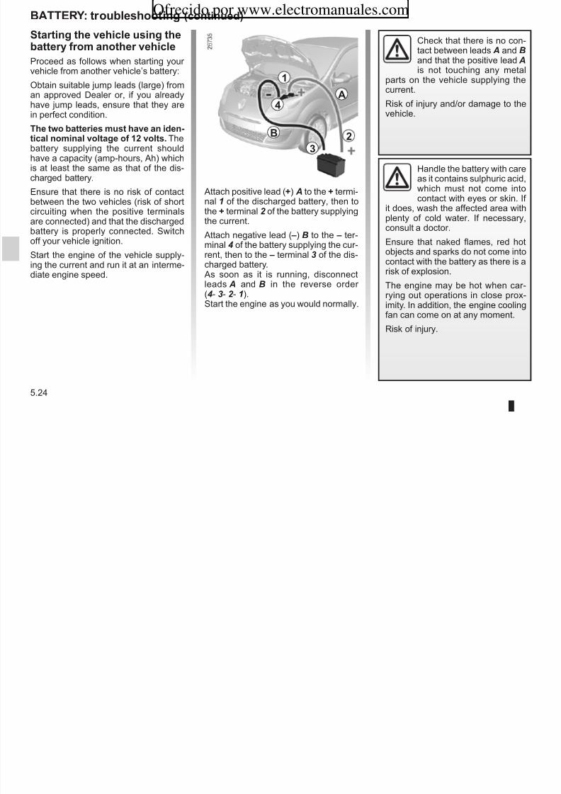
8/6/2019 NU773-8_ENG
http://slidepdf.com/reader/full/nu773-8eng 182/223
5.24
Ensure that there is no risk of contactbetween the two vehicles (risk of shortcircuiting when the positive terminalsare connected) and that the dischargedbattery is properly connected. Switch
off your vehicle ignition.
Start the engine of the vehicle supply-ing the current and run it at an interme-diate engine speed.
Attach positive lead (+) A to the + termi-nal 1 of the discharged battery, then tothe + terminal 2 of the battery supplyingthe current.
Attach negative lead ( –) B to the – ter-minal 4 of the battery supplying the cur-rent, then to the – terminal 3 of the dis-charged battery.As soon as it is running, disconnectleads A and B in the reverse order (4- 3 - 2 - 1).Start the engine as you would normally.
which must not come intocontact with eyes or skin. If
it does, wash the affected area withplenty of cold water. If necessary,consult a doctor.
Ensure that naked flames, red hotobjects and sparks do not come intocontact with the battery as there is arisk of explosion.
The engine may be hot when car-rying out operations in close prox-imity. In addition, the engine coolingfan can come on at any moment.
Risk of injury.
rADIO FreQuencY reMOte cOntrOL: BAtterIeS
r l i h b n It i t d i bl t t h th
1
3
2
Ofrecido por www.electromanuales.com
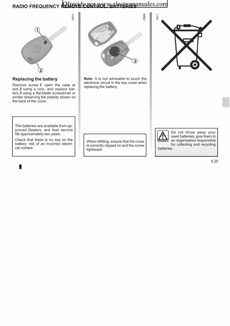
8/6/2019 NU773-8_ENG
http://slidepdf.com/reader/full/nu773-8eng 183/223
5.25
rplai h bay
Remove screw 1, open the case atslot 2 using a coin, and replace bat-tery 3 using a flat-blade screwdriver or
similar observing the polarity shown onthe back of the cover.
no: It is not advisable to touch theelectronic circuit in the key cover whenreplacing the battery.
Do not throw away your used batteries; give them toan organisation responsiblefor collecting and recycling
batteries.
When refitting, ensure that the cover is correctly clipped on and the screwtightened.
The batteries are available from ap-proved Dealers, and their servicelife approximately two years.
Check that there is no dye on thebattery: risk of an incorrect electri-cal contact.
F b
FuSeS (1/3)
cli 3
1 2
3
Ofrecido por www.electromanuales.com

8/6/2019 NU773-8_ENG
http://slidepdf.com/reader/full/nu773-8eng 184/223
5.26
Fs box
If electrical equipment does not work,check the condition of the fuses.
Depending on the vehicle, open cover 1
to the left of the steering wheel or glove-box 2 . To locate the fuses, use the fuelallocation label (covered in the pagesthat follow).
It is not advisable to use the free fuselocations.
Check the fuse in questionand pla i, if necessary,wih a fs of h samai.
If a fuse is fitted where the rating istoo high, it may cause the electricalcircuit to overheat (risk of fire) in theevent of an item of equipment using
an excessive amount of current.
In accordance with local legislationor as a precautionary measure:
Obtain an emergency kit containinga set of spare bulbs and fuses froman approved dealer.
clip 3
Remove the fuse using tweezers 3 , lo-cated on the back of cover 1 or in glovebox 2 .
To remove the fuse from the tweezers,slide the fuse to the side.
FuSeS (2/3)
nmbs Alloaio
1 and 2Windscreen wipers/Rev counter.
3Power-assistedsteering.
4, 16 and 27 Sequential gearbox.
5Brake light/Speedlimiter.
nmbs Alloaio
11 Direction indicator lights/Diagnosticsocket.
12 Power supply/Instrument panel.
13 Dipped beamheadlights/Rear foglight.
14 Electric door locking.
nmbs Alloaio
21 Main beam headlights/Horn.
22 Main beam headlights.
23 and 31 Electric windows.
24 and 28 Passenger compartment
Alloaio of fss (the presence of fuses DEPENDS ON THE EQUIPMENT LEVEL OF THE VEHICLE)
Ofrecido por www.electromanuales.com

8/6/2019 NU773-8_ENG
http://slidepdf.com/reader/full/nu773-8eng 185/223
5.27
6
Reversing light/Rear view mirror control/Alarm siren/Parkingdistance control.
7 Air bag.
8Passenger compartment electricalunit/Instrument panel.
9 Injection.
10 ABS/ASR/ESP.
15 Side lights/Front foglights.
17 Heated rear screen/Heated door mirrors.
18 Interior lighting/Courtesy light/Heatingand air conditioningsystem/Rev counter.
19 Side lights.
20 Front and rear foglights.
ventilation.
25 Dipped beamheadlights/Front andrear fog lights.
26 Sunroof.
29 Radio/Passenger compartment electricalunit/Air conditioning/Instrument panel/Heated seat.
30 Cigar lighter.
32 Right-hand main beamheadlight.
FuSeS (3/3)
nmbs Alloaio
33 Left-hand mainbeam headlight andinstrument panelindicator light.
34 Right-hand dipped
beam headlight.
35 Left-hand dippedbeam headlight andinstrument panelindicator light
nmbs Alloaio
42 Right-hand sidelight/Passenger compartmentinstrument lighting
43 Left-hand side light.
44 Location reserved for additional equipment.
Alloaio of fss (the presence of fuses DEPENDS ON THE EQUIPMENT LEVEL OF THE VEHICLE)
Ofrecido por www.electromanuales.com

8/6/2019 NU773-8_ENG
http://slidepdf.com/reader/full/nu773-8eng 186/223
5.28
indicator light.
36 Rear screen wiper.
37 Heated door mirrors.
38 Horn.
39 Rear fog lights.
40 Location reserved for additional equipment.
41 Heated seats.
45 Driver’s door switch.
48 Radio/Alarm/Display.
tOWIng: bakdow
th si whl ms b - us oly h owi pois a h Ass o fo owi
5
1
3
4
2
Ofrecido por www.electromanuales.com

8/6/2019 NU773-8_ENG
http://slidepdf.com/reader/full/nu773-8eng 187/223
5.29
th si whl ms b lokd ad h iiio ky ms bi h “Iiio o” posiio o po-vid sials (bak lihs ad di-io idiaos) o h owd vhi-
l. A ih h vhil ms havis lihs o.
You must observe the towing regu-lations which apply in the country inwhich you are driving: do not exceedthe towing weight for your vehicle.Contact your RENAULT Dealer.
us oly h owi pois a hfo 2 ad a 5 (never use the driveshafts). These towing points may onlybe used for pulling the vehicle, never for lifting it either directly or indirectly.
Ass o fo owipoi 2
Unclip cover 4.
Sw i owi hih 3 flly: firstly
by hand, then finish by tightening it withthe wheelbrace.
The towing hitch 3 and wheelbrace arelocated in the tool kit 1.
When the engine isstopped, steering and brak-ing assistance are not op-erational.
Do not leave the tools unse-cured inside the vehicle asthey may come loose under braking.
tOWIng: bakdow (oid)
U i id t i b
Ofrecido por www.electromanuales.com

8/6/2019 NU773-8_ENG
http://slidepdf.com/reader/full/nu773-8eng 188/223
5.30
When the engine isstopped, steering and brak-ing assistance are not op-erational.
– Use a rigid towing bar.If a rope or cable is used(where the law allows this),the vehicle being towed
must be able to brake.
– A vehicle must not be towed if it isnot fit to be driven.
– Avoid accelerating or brakingsuddenly when towing, as thismay result in damage beingcaused to the vehicle.
– When towing a vehicle, it is ad-visable not to exceed 15 mph
(25 km/h).
A = 600 mm.
tOWIng: owi qipm
A
Ofrecido por www.electromanuales.com

8/6/2019 NU773-8_ENG
http://slidepdf.com/reader/full/nu773-8eng 189/223
5.31
Pmissibl os wih, maxi-mm pmissibl owi wihbakd ad bakd:
Refer to the information on “Weights”in Section 6.
Refer to the manufacturer’s instruc-tions for information on how to fitand operate the towing equipment.
Please keep these instructions withthe rest of the vehicle documenta-tion.
FIttIng tHe rADIO
radio loaio 1 tw spaks Fo doo spaks 3
1
2
3
Ofrecido por www.electromanuales.com

8/6/2019 NU773-8_ENG
http://slidepdf.com/reader/full/nu773-8eng 190/223
5.32
Unclip and remove the cover. The aerial(depending on vehicle), + and – supplyconnectors and left-hand and righthandspeaker wires are fixed to the rear faceof the cover.
p(depending on vehicle)
Using a flat-blade screwdriver or simi-lar, unclip grille 2 to access the speaker wires.
p(depending on vehicle)
Consult an approved dealer.
– In all cases, it is very important to follow the manufacturer’s instructions carefully.
– The specifications of the brackets and wires (available at approved accessory outlets) vary depending on the equipmentlevel of your vehicle and the type of radio.Consult an approved dealer to find out the correct part number.
– No work may be carried out on the vehicle’s electrical or radio circuits, except by approved dealers: an incorrectly connectedsystem may result in damage being caused to the electrical equipment and/or the components connected to it.
Spaks i a pals 4
FIttIng tHe rADIO (oid)
4
Loaio of aial 5
5
Ofrecido por www.electromanuales.com

8/6/2019 NU773-8_ENG
http://slidepdf.com/reader/full/nu773-8eng 191/223
5.33
p p(depending on vehicle)
Consult an approved dealer.
(depending on vehicle)
Consult an approved dealer.
– In all cases, it is very important to follow the manufacturer’s instructions carefully.
– The specifications of the brackets and wires (available at approved accessory outlets) vary depending on the equipmentlevel of your vehicle and the type of radio.
Consult an approved dealer to find out the correct part number. – No work may be carried out on the vehicle’s electrical or radio circuits, except by approved dealers: an incorrectly connected
system may result in damage being caused to the electrical equipment and/or the components connected to it.
AcceSSOrIeS
elial ad loiassois
– Connect accessorieswith a maximum power of
120 Watts only.
Fi hazad.
No work may be carried out onus of asmissio/
Before fitting an electrical or electronic device (particu-larly for transmitters/receiv-ers: frequency bandwidth,
power level, position of the aerialetc.), ensure that it is compatiblewith your vehicle.
Contact an approved dealer for thisinformation.
If you are using an anti-theftdevice, only attach it to thebrake pedal.
Ofrecido por www.electromanuales.com

8/6/2019 NU773-8_ENG
http://slidepdf.com/reader/full/nu773-8eng 192/223
5.34
Fii af-makassoisIf you wish to install acces-
sories on the vehicle: con-sult an approved dealer.Also, to ensure the correct opera-tion of your vehicle, and to avoidany risk to your safety, we recom-mend that you use only specific ac-cessories, designed for your vehi-cle, which are the only accessoriesfor which the manufacturer will pro-vide a warranty.
– No work may be carried out onthe vehicle’s electrical or radiocircuits, except by approvedDealers: an incorrectly con-
nected system may result indamage being caused to theelectrical equipment and/or thecomponents connected to it;
– if the vehicle is fitted with anyaftermarket electrical equip-ment, make sure that the unitis correctly protected by a fuse.Establish the rating and positionof this fuse.
us of asmissio/ivi dvis(lphos, cBqipm .).
Telephones and CB equipment withintegrated aerials may cause inter-ference to the original electronicsystems fitted to the vehicle: it is ad-visable only to use equipment withan external aerial.
Fhmo, w mid yo of h d o omply wih h lis-laio i fo oi h sof sh qipm.
OPerAtIng FAuLtS (1/5)
th followi advi will abl yo o ay o qik, mpoay pais. Fo safy asos yo shold always oa
a renAuLt Dal as soo as possibl.
th sa is aivad POSSIBLe cAuSeS WHAt tO DO
The indicator lights fail to light up andthe starter does not turn.
Battery terminals disconnected,oxidised or incorrectly secured.
Retighten, reconnect or clean them if theyare oxidised.
Battery discharged or unservice-able.
Connect another battery to the faulty bat-tery. Refer to the paragraph “Battery: trou-bleshooting” in section 5 or replace the bat-
tery if necessary.Do not push the vehicle if the steeringcolumn is locked.
Ofrecido por www.electromanuales.com

8/6/2019 NU773-8_ENG
http://slidepdf.com/reader/full/nu773-8eng 193/223
5.35
The engine will not start. Starting conditions are not fulfilled. Refer to the information on “Starting/stop-ping the engine” in Section 2.
The steering column remains locked. Steering wheel locked. To unlock, move the key and the steeringwheel gently (refer to the information on the“Ignition switch” in Section 2).
OPerAtIng FAuLtS (2/5)
O h oad POSSIBLe cAuSeS WHAt tO DO
Coolant boiling in the coolant reser-voir.
Mechanical fault: cylinder headgasket damaged, faulty coolantpump.
Stop the engine.Contact an approved Dealer.
Smoke under the bonnet. Short circuit or cooling system leak. Stop, switch off the ignition, stand awayfrom the vehicle and contact an approvedDealer.
The oil pressure warning light comeson:
while cornering or braking The level is too low. Top up the engine oil (refer to the informa-tion on “Engine oil level - Topping up/refill-ing” in Section 4).
Ofrecido por www.electromanuales.com

8/6/2019 NU773-8_ENG
http://slidepdf.com/reader/full/nu773-8eng 194/223
5.36
g )
at idle speed Low oil pressure. Consult the nearest approved dealer.
is slow to go out or remains lit under acceleration
Loss of oil pressure. Stop the vehicle and contact an approvedDealer.
White smoke from the exhaust. This is not necessarily a fault. Smokemay be caused by regeneration of the particle filter.
Refer to the information on “Special fea-tures of diesel versions” in Section 2.
OPerAtIng FAuLtS (3/5)
O h oad POSSIBLe cAuSeS WHAt tO DO
Vibrations Tyres not inflated to correct pres-sures, incorrectly balanced or dam-aged.
Check the tyre pressures: if this is not theproblem, have them checked by an ap-proved dealer.
whistling roof aerial incorrectly positioned Fold down the aerial until the end of it is ap-proximately 44 cm from the vehicle’s roof.
Steering becomes heavy. Assistance overheating.
Low battery.
Leave to cool.
Recharge or replace the battery.
Ofrecido por www.electromanuales.com

8/6/2019 NU773-8_ENG
http://slidepdf.com/reader/full/nu773-8eng 195/223
5.37
The engine overheats. The coolanttemperature indicator and the STOPwarning light come on.
Engine cooling fan not working. Stop the vehicle, switch off the engine andcontact an approved Dealer.
Coolant leaks. Check the coolant reservoir: it should con-tain fluid. If there is no coolant, consult your approved Dealer as soon as possible.
radiao: If there is a significant lack of coolant, remember that it must never be topped up using cold coolant whilethe engine is very warm. After any procedure on the vehicle which has involved even partial draining of the cooling
system, it must be refilled with a new mixture prepared in the correct proportions. Reminder: only products approvedby our Technical Department may be used for this purpose.
OPerAtIng FAuLtS (4/5)
elial qipm POSSIBLe cAuSeS WHAt tO DO
The wipers do not work. Wiper blades stuck. Free the blades before using the wipers.
Faulty electrical circuit. Consult an approved Dealer.
The wiper does not stop. Faulty electrical controls. Consult an approved Dealer.
Direction indicators flashing morequickly.
Blown bulb. Replace the bulb.
Ofrecido por www.electromanuales.com

8/6/2019 NU773-8_ENG
http://slidepdf.com/reader/full/nu773-8eng 196/223
5.38
The direction indicators do not work. Faulty electrical circuit. Consult an approved Dealer.
The headlights do not switch on or off. Faulty electrical circuit or control. Consult an approved Dealer.
Traces of condensation in the lights. This is not a fault. Traces of condensa-tion are a natural phenomenon causedby variations in temperature.
These traces soon disappear when thelights are switched on.
OPerAtIng FAuLtS (5/5)
elial qipm POSSIBLe cAuSeS WHAt tO DO
The sunroof does not open/close. Sunroof opening conditions not ful-filled.
Apply the opening conditions (refer to theinformation on the “Electric sunroof” inSection 3).
Roof fault.
Electrical fault (discharged battery,etc.).
Leave the sunroof closed or close it using
the methods described in “Electric sunroof:Operating fault” in Section 3 and contactyour approved dealer.
Ofrecido por www.electromanuales.com

8/6/2019 NU773-8_ENG
http://slidepdf.com/reader/full/nu773-8eng 197/223
5.39
Ofrecido por www.electromanuales.com

8/6/2019 NU773-8_ENG
http://slidepdf.com/reader/full/nu773-8eng 198/223
5.40
Section 6: Technical specificationsOfrecido por www.electromanuales.com

8/6/2019 NU773-8_ENG
http://slidepdf.com/reader/full/nu773-8eng 199/223
6.1
Vehicle identification plates . . . . . . . . . . . . . . . . . . . . . . . . . . . . . . . . . . . . . . . . . . . . . . . . . . . . . . . . 6.2Engine specifications . . . . . . . . . . . . . . . . . . . . . . . . . . . . . . . . . . . . . . . . . . . . . . . . . . . . . . . . . . . . . 6.4Dimensions . . . . . . . . . . . . . . . . . . . . . . . . . . . . . . . . . . . . . . . . . . . . . . . . . . . . . . . . . . . . . . . . . . . . 6.5
Weights . . . . . . . . . . . . . . . . . . . . . . . . . . . . . . . . . . . . . . . . . . . . . . . . . . . . . . . . . . . . . . . . . . . . . . . 6.6Replacement parts and repairs . . . . . . . . . . . . . . . . . . . . . . . . . . . . . . . . . . . . . . . . . . . . . . . . . . . . . 6.7Service sheets . . . . . . . . . . . . . . . . . . . . . . . . . . . . . . . . . . . . . . . . . . . . . . . . . . . . . . . . . . . . . . . . . . 6.8Anticorrosion check . . . . . . . . . . . . . . . . . . . . . . . . . . . . . . . . . . . . . . . . . . . . . . . . . . . . . . . . . . . . . . 6.14
VEHICLE IDENTIFICATION PLATES (1/2)
Quote the details given on the iden-tification plate A (right-hand side) on
6 Technical specifications of the ve-hicle.
A
54
A 6
7
89
10
11
12
13
1
3
2
Ofrecido por www.electromanuales.com

8/6/2019 NU773-8_ENG
http://slidepdf.com/reader/full/nu773-8eng 200/223
6.2
all communication or orders.
A - Vehicle identification plate 1 Vehicle type and chassis number.
Depending on the vehicle, this in-formation is also given on mark-ing B.
2 Maximum permissible all-upweight.
3 Total train weight (vehicle fullyloaded, with trailer).
4 Maximum permissible weight onfront axle.
5 Maximum permissible weight onrear axle.
7 Vehicle paint reference. 8 Equipment level. 9 Vehicle type.
10 Trim code. 11 Additional equipment specifica-tion.
12 Fabrication number. 13 Interior trim code.
B
Quote the details given on engineplate C on all communication or
VEHICLE IDENTIFICATION PLATES (2/2)
CC
1
23
C
Ofrecido por www.electromanuales.com

8/6/2019 NU773-8_ENG
http://slidepdf.com/reader/full/nu773-8eng 201/223
6.3
orders.
C - Engine plate or engine
label
(location varies depending on engine)
1 Engine type
2 Engine suffix
3 Engine number CC
ENGINE SPECIFICATIONS
Engine type(see engine plate)
D7F D4F 1.2 TCE K9K
Cubic capacity (cc) 1 149 1 149 1 149 1 461
Type of fuel It is essential to use unleaded petrol of the Octane Rating stated on the labelinside the fuel filler flap.
If not available, for a limited time only, unleaded fuel may be used: – with an octane rating of 91 for a label showing 95 or 98;
– with an octane rating of 87 for a label showing 91, 95 or 98.
Diesel.The label located
in the fuel filler flap indicates
authorised fuels.
Ofrecido por www.electromanuales.com

8/6/2019 NU773-8_ENG
http://slidepdf.com/reader/full/nu773-8eng 202/223
6.4
Spar plugs Only use the spark plugs specified for your vehicle’s engine. The type shouldbe marked on a label stuck inside the engine compartment. If it is not then con-
tact your RENAULT Dealer. Fitting spark plugs which are not to specificationmay damage the engine. –
DIMENSIONS (in metres)
3 6021.927
1.400 / 1.4140.710 0.5252.367
Ofrecido por www.electromanuales.com

8/6/2019 NU773-8_ENG
http://slidepdf.com/reader/full/nu773-8eng 203/223
6.5
(1) unladen
3.602
1.470 (1)
1.386 / 1.400
WEIGHTS (in g)
The weights indicated for a basic vehicle without options: they vary depending on the your vehicle’s equipment. Contactan approved Dealer.
Maximum permissible all-up weight (MMAC)Total train weight (MTR)
Weights indicated on the vehicle identification plate
(refer to the information on the “Vehicleidentification plates” in Section 6)
Towing weight braed found by calculating: MTR - MMAC
Towing weight unbraed 350
Permissible nose weight 65
Maximum permissible load on roof rac 60 (including the carrying device)
Towing weight (Towing a caravan, boat, etc.)
– It is important to comply with the towing weights, governed by local legislation in each country and, in particular, laid down inthe Road Traffic Regulations Contact an approved Dealer about any towing equipment
Ofrecido por www.electromanuales.com

8/6/2019 NU773-8_ENG
http://slidepdf.com/reader/full/nu773-8eng 204/223
6.6
the Road Traffic Regulations. Contact an approved Dealer about any towing equipment.
– When towing, under no circumstances may the total train weight (vehicle + trailer) be exceeded. However the following ispermitted:
– up to 15% over the maximum permissible all-up weight for the rear,
– 10% or 100 kg over the maximum permissible all-up weight (whichever limit is reached first).
In either case, the maximum speed of the towing assembly must not exceed 60 mph (100 km/h) and the tyre pressure must beincreased by 0.2 bar (3 PSI).
– The engine output and climbing capability are reduced with altitude. We recommend that the maximum load be reduced by 10%at an altitude of 1,000 metres and by an additional 10% for each 1,000 metres thereafter.
Original parts are based on strict specifications and are subject to highly-specialised tests. Therefore, they are of at least the samelevel of quality as the parts fitted originally.
If you always fit genuine replacement parts to your vehicle, you will ensure that it performs well. Furthermore, repairs carried outwithin the manufacturer’s Network using original parts are guaranteed according to the conditions set out on the reverse of therepair order.
REPLACEMENT PARTS AND REPAIRSOfrecido por www.electromanuales.com

8/6/2019 NU773-8_ENG
http://slidepdf.com/reader/full/nu773-8eng 205/223
6.7
SERVICE SHEETS
Date: Miles (km): Invoice number: Comments/miscellaneous
Type of operation: Stamp
Service □
....................................... □
Anticorrosion chec:
OK□ NotOK*□
*Seespecificpage
Date: Miles (km): Invoice number: Comments/miscellaneous
Type of operation: Stamp
Service □
□
VIN: ..................................................................................
Ofrecido por www.electromanuales.com

8/6/2019 NU773-8_ENG
http://slidepdf.com/reader/full/nu773-8eng 206/223
6.8
....................................... □
Anticorrosion chec:
OK□ NotOK*□
*Seespecificpage
Date: Miles (km): Invoice number: Comments/miscellaneous
Type of operation: Stamp
Service □
....................................... □
Anticorrosion chec:
OK□ NotOK*□
*Seespecificpage
SERVICE SHEETS (continued)
VIN: ..................................................................................
Date: Miles (km): Invoice number: Comments/miscellaneous
Type of operation: Stamp
Service □
....................................... □
Anticorrosion chec:
OK□ NotOK*□
*Seespecificpage
Date: Miles (km): Invoice number: Comments/miscellaneous
Type of operation: Stamp
Service □
....................................... □
Ofrecido por www.electromanuales.com
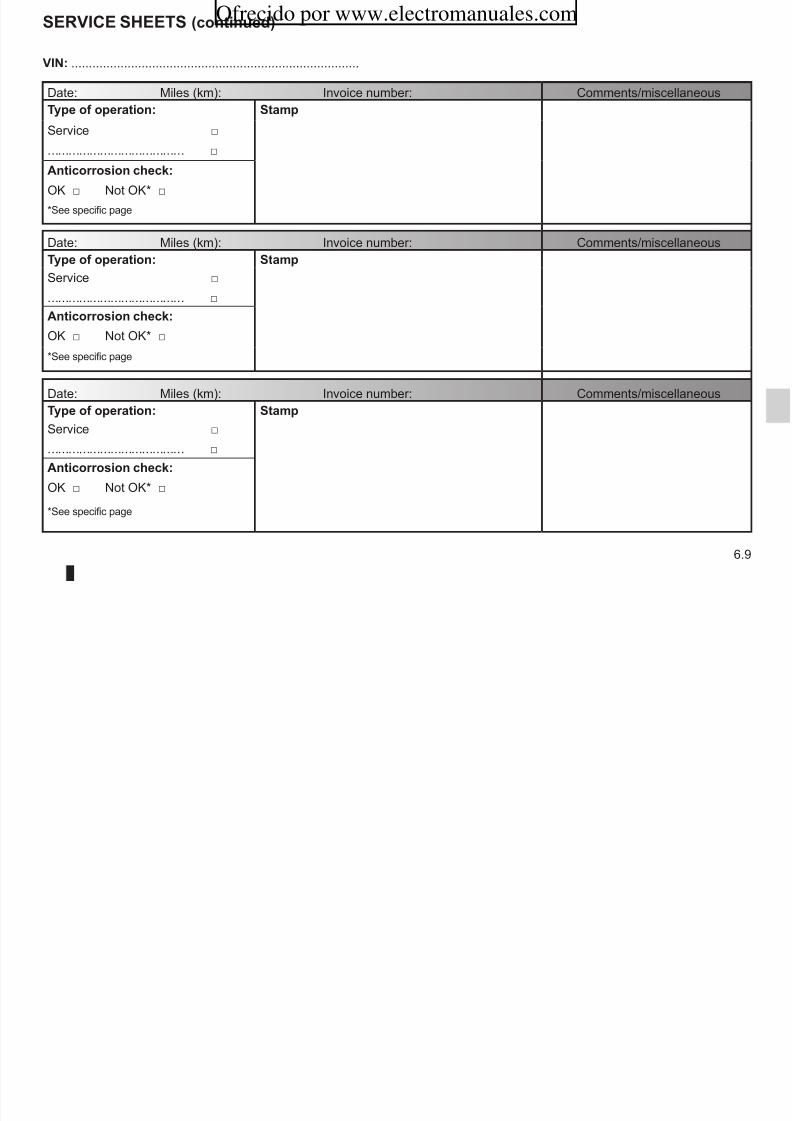
8/6/2019 NU773-8_ENG
http://slidepdf.com/reader/full/nu773-8eng 207/223
6.9
....................................... □
Anticorrosion chec:
OK□ NotOK*□
*Seespecificpage
Date: Miles (km): Invoice number: Comments/miscellaneous
Type of operation: Stamp
Service □
....................................... □
Anticorrosion chec:
OK□ NotOK*□
*Seespecificpage
SERVICE SHEETS (continued)
VIN: ..................................................................................
Date: Miles (km): Invoice number: Comments/miscellaneous
Type of operation: Stamp
Service □
....................................... □
Anticorrosion chec:
OK□ NotOK*□
*Seespecificpage
Date: Miles (km): Invoice number: Comments/miscellaneous
Type of operation: Stamp
Service □
....................................... □
Ofrecido por www.electromanuales.com

8/6/2019 NU773-8_ENG
http://slidepdf.com/reader/full/nu773-8eng 208/223
6.10
Anticorrosion chec:
OK□ NotOK*□
*Seespecificpage
Date: Miles (km): Invoice number: Comments/miscellaneous
Type of operation: Stamp
Service □
....................................... □
Anticorrosion chec:
OK□ NotOK*□
*Seespecificpage
SERVICE SHEETS (continued)
VIN: ..................................................................................
Date: Miles (km): Invoice number: Comments/miscellaneous
Type of operation: Stamp
Service □
....................................... □
Anticorrosion chec:
OK□ NotOK*□
*Seespecificpage
Date: Miles (km): Invoice number: Comments/miscellaneous
Type of operation: Stamp
Service □
....................................... □
Ofrecido por www.electromanuales.com
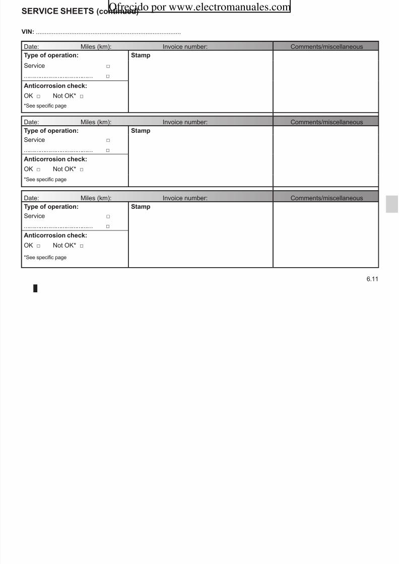
8/6/2019 NU773-8_ENG
http://slidepdf.com/reader/full/nu773-8eng 209/223
6.11
Anticorrosion chec:
OK□ NotOK*□
*Seespecificpage
Date: Miles (km): Invoice number: Comments/miscellaneous
Type of operation: Stamp
Service □
....................................... □
Anticorrosion chec:
OK□ NotOK*□
*Seespecificpage
SERVICE SHEETS (continued)
VIN: ..................................................................................
Date: Miles (km): Invoice number: Comments/miscellaneous
Type of operation: Stamp
Service □
....................................... □
Anticorrosion chec:
OK□ NotOK*□
*Seespecificpage
Date: Miles (km): Invoice number: Comments/miscellaneous
Type of operation: Stamp
Service □
....................................... □
Ofrecido por www.electromanuales.com

8/6/2019 NU773-8_ENG
http://slidepdf.com/reader/full/nu773-8eng 210/223
6.12
Anticorrosion chec:
OK□ NotOK*□
*Seespecificpage
Date: Miles (km): Invoice number: Comments/miscellaneous
Type of operation: Stamp
Service □
....................................... □
Anticorrosion chec:
OK□ NotOK*□
*Seespecificpage
SERVICE SHEETS (continued)
VIN: ..................................................................................
Date: Miles (km): Invoice number: Comments/miscellaneous
Type of operation: Stamp
Service □
....................................... □
Anticorrosion chec:
OK□ NotOK*□
*Seespecificpage
Date: Miles (km): Invoice number: Comments/miscellaneous
Type of operation: Stamp
Service □
....................................... □
Ofrecido por www.electromanuales.com

8/6/2019 NU773-8_ENG
http://slidepdf.com/reader/full/nu773-8eng 211/223
6.13
Anticorrosion chec:
OK□ NotOK*□
*Seespecificpage
Date: Miles (km): Invoice number: Comments/miscellaneous
Type of operation: Stamp
Service □
....................................... □
Anticorrosion chec:
OK□ NotOK*□
*Seespecificpage
ANTICORROSION CHECk
If the continuation of the warranty is subject to repair, it is indicated below.
VIN: ..........................................................
Corrosion repair operation to be carriedout:
Stamp
Date of repair:
Repair to be carried out: Stamp
Ofrecido por www.electromanuales.com
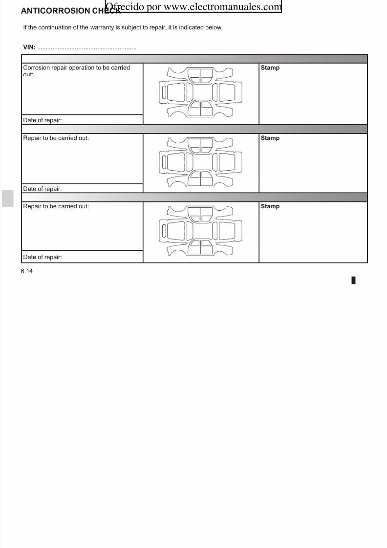
8/6/2019 NU773-8_ENG
http://slidepdf.com/reader/full/nu773-8eng 212/223
6.14
Date of repair:
Repair to be carried out: Stamp
Date of repair:
ANTICORROSION CHECk (continued)
If the continuation of the warranty is subject to repair, it is indicated below.
VIN: ..........................................................
Corrosion repair operation to be carriedout:
Stamp
Date of repair:
Repair to be carried out: Stamp
Ofrecido por www.electromanuales.com

8/6/2019 NU773-8_ENG
http://slidepdf.com/reader/full/nu773-8eng 213/223
6.15
Date of repair:
Repair to be carried out: Stamp
Date of repair:
ANTICORROSION CHECk (continued)
If the continuation of the warranty is subject to repair, it is indicated below.
VIN: ..........................................................
Corrosion repair operation to be carriedout:
Stamp
Date of repair:
Repair to be carried out: Stamp
Ofrecido por www.electromanuales.com

8/6/2019 NU773-8_ENG
http://slidepdf.com/reader/full/nu773-8eng 214/223
6.16
Date of repair:
Repair to be carried out: Stamp
Date of repair:
ANTICORROSION CHECk (continued)
If the continuation of the warranty is subject to repair, it is indicated below.
VIN: ..........................................................
Corrosion repair operation to be carriedout:
Stamp
Date of repair:
Repair to be carried out: Stamp
Ofrecido por www.electromanuales.com

8/6/2019 NU773-8_ENG
http://slidepdf.com/reader/full/nu773-8eng 215/223
6.17
Date of repair:
Repair to be carried out: Stamp
Date of repair:
ANTICORROSION CHECk (continued)
If the continuation of the warranty is subject to repair, it is indicated below.
VIN: ..........................................................
Corrosion repair operation to be carriedout:
Stamp
Date of repair:
Repair to be carried out: Stamp
Ofrecido por www.electromanuales.com
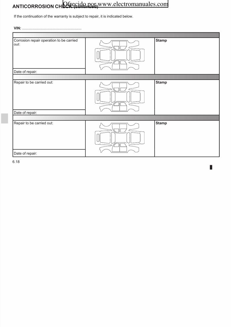
8/6/2019 NU773-8_ENG
http://slidepdf.com/reader/full/nu773-8eng 216/223
6.18
Date of repair:
Repair to be carried out: Stamp
Date of repair:
AlphAbeticAl index (1/4)
AABS .......................................................................2.12 → 2.14
accessories........................................................................5.34accessories socket ............................................................3.30additional methods of restraint ..........................................1.26
to the front seat belts .......................................1.20 → 1.23
additional systems to the seat belts........................ 1.24 – 1.25adjusting the seats.............................................................3.33adjusting your driving position ................................1.16 – 1.17air bag................................................1.20 → 1.23, 1.25 – 1.26
air conditioning ........................................................3.7 → 3.18
air vents ...................................................................... 3.2 – 3.3
anti-corrosion check ..............................................6.14 → 6.18anti-lock braking system: ABS ...............................2.12 → 2.14
antipollutionadvice ................................................................2.8 → 2.10
ashtray ...............................................................................3.30ASR (traction control) ............................................2.12 → 2.14
audible and visual signals..................................................1.63automatic gearbox (use) ....................................................2.23
changing gear ......................................................................2.6child restraint/seat .............................1.27 – 1.28, 1.30 → 1.39
child safety..................................1.2, 1.27 – 1.28, 1.30 → 1.39child seats..........................................1.27 – 1.28, 1.30 → 1.39
children ................................................................... 1.27 – 1.28cigar lighter ........................................................................3.30clock .......................................................................1.55 – 1.56controls ...........................................................1.46 → 1.49, 3.9
coolant .................................................................................4.8courtesy light .....................................................................5.21courtesy mirrors .................................................................3.23cruise control .........................................................2.15 → 2.21
cruise control-speed limiter....................................2.15 → 2.21
dde-icing
rear screen ................................................................... 3.15demisting
rear screen ..................................................................... 3.5dimensions ..........................................................................6.5
Ofrecido por www.electromanuales.com
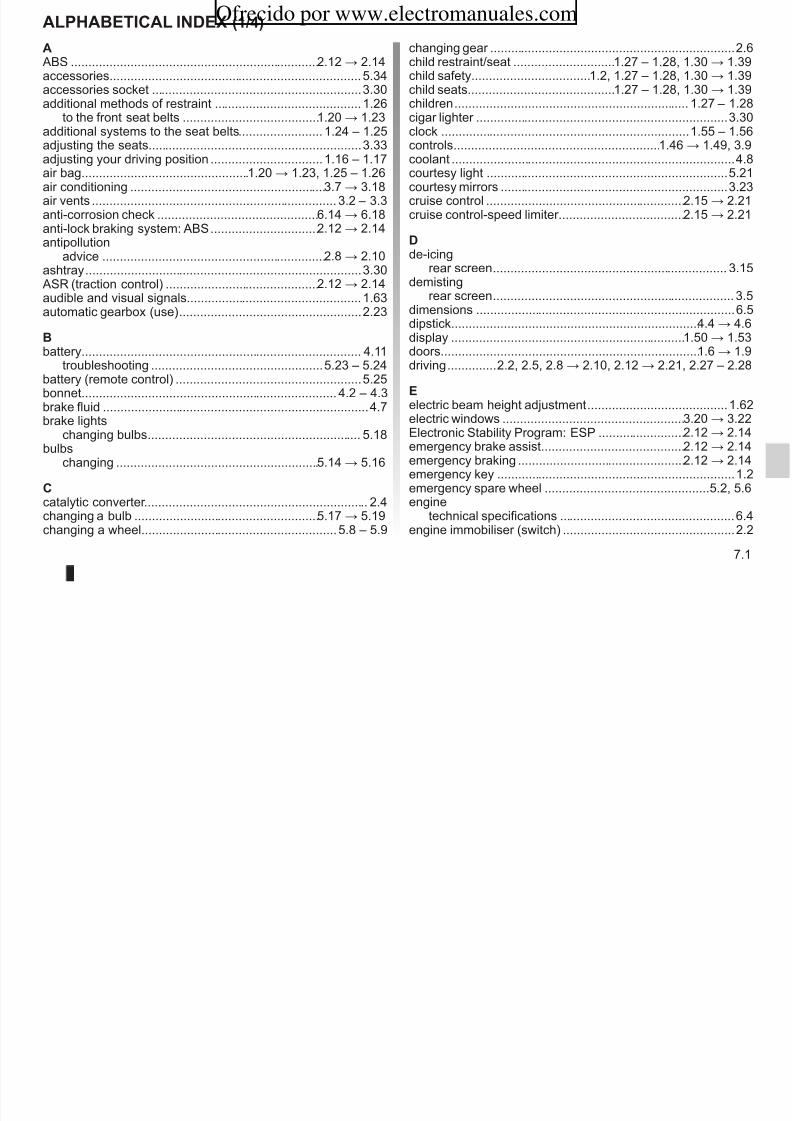
8/6/2019 NU773-8_ENG
http://slidepdf.com/reader/full/nu773-8eng 217/223
7.1
g ( )
b
battery................................................................................ 4.11troubleshooting .................................................5.23 – 5.24
battery (remote control) .....................................................5.25bonnet......................................................................... 4.2 – 4.3brake fluid ............................................................................4.7brake lights
changing bulbs ............................................................. 5.18bulbs
changing ..........................................................5.14 → 5.16
ccatalytic converter................................................................ 2.4changing a bulb .....................................................5.17 → 5.19
changing a wheel........................................................5.8 – 5.9
dipstick.......................................................................4.4 → 4.6
display ...................................................................1.50 → 1.53
doors..........................................................................1.6 → 1.9driving ..............2.2, 2.5, 2.8 → 2.10, 2.12 → 2.21, 2.27 – 2.28
eelectric beam height adjustment ........................................1.62electric windows ....................................................3.20 → 3.22
Electronic Stability Program: ESP .........................2.12 → 2.14
emergency brake assist.........................................2.12 → 2.14
emergency braking ................................................2.12 → 2.14
emergency key ....................................................................1.2
emergency spare wheel ............................................... 5.2, 5.6engine
technical specifications ..................................................6.4engine immobiliser (switch) .................................................2.2
AlphAbeticAl index (2/4)
engine oil ...................................................................4.4 → 4.9
engine oil capacity .....................................................4.4 → 4.6
engine oil level ....................................................4.4, 4.7 → 4.9engine specifications ...........................................................6.4environment ....................................................................... 2.11ESP: Electronic Stability Program .........................2.12 → 2.14
external temperature ..............................................1.55 – 1.56
Ffaults
operating faults ................................................5.35 → 5.39
filter
air filter .................................................................... 2.8, 4.9diesel filter ............................................................... 2.8, 4.9
oil filter ...........................................................................4.6passenger compartment filter ........................................4.9
fitting a radio ........................................................... 5.32 – 5.33fog lights ............................................................................5.16front lights
changing bulbs .................................................5.14 → 5.16
hhandbrake............................................................................2.7
hazard warning lights signal ..............................................1.63headlight beam adjustment ...............................................1.62headrest....................................................................1.12, 3.31
heated seats ......................................................................1.13heating and air conditioning system ........................3.7 → 3.17
heating system ........................................................3.4 → 3.18
horn ...................................................................................2.24hubcap tool ..........................................................................5.6
i
ignition switch ......................................................................2.2indicators .................................................................. 1.50, 5.14
indicators:exterior temperature indicator ......................................1.55
instrument panel ....................................................1.46 → 1.53
interior lighting:changing bulbs ..................................................5.21 – 5.22
J
Ofrecido por www.electromanuales.com

8/6/2019 NU773-8_ENG
http://slidepdf.com/reader/full/nu773-8eng 218/223
7.2
front seat adjustment .........................................................1.13front seats ..............................................................1.13 → 1.15
fueladvice on fuel economy .....................................2.8 → 2.10
filling .............................................................................1.68grade ..............................................................................6.4
fuel economy ...........................................................2.8 → 2.10
fuel grade...........................................................................1.67fuel level ............................................................................1.50fuel tank .................................................................. 1.67 – 1.68fuel tank capacity ............................................................... 1.67fuses ......................................................................5.26 → 5.28
Ggear lever............................................................................. 2.6
J jack ......................................................................................5.2
Kkeys ............................................................................ 1.2 – 1.3
llevels:
engine oil ..............................................................4.5 – 4.6lighting:
exterior .............................................................1.58 → 1.61
interior ...................................................... 3.19, 5.21 – 5.22
lightsadditional .....................................................................5.16changing bulbs .................................................5.14 → 5.16
fog lights ......................................................................5.16
AlphAbeticAl index (3/4)
front ..................................................................5.14 → 5.16
lights:
brake lights ..................................................................5.17dipped beam headlights ......................................1.59, 5.15
direction indicator lights ...................................... 5.15, 5.17
direction indicators .......................................................1.63fog lights .................................................. 1.61, 5.16 – 5.17
hazard warning ............................................................1.63indicator lights ..............................................................5.20main beam headlights .........................................1.60, 5.15
number plate lights ......................................................5.19reversing lights ............................................................. 5.17
side lights ............................................................ 1.58, 5.15lights-on warning buzzer....................................................1.60locking the doors .......................................................1.4 → 1.9
luggage compartment cover ..............................................3.38luggage compartment lighting
changing bulbs ............................................................. 5.22
Mi t 2 8
reference ............................................................... 6.2 – 6.3parking distance control.......................................... 2.27 – 2.28
power-assisted steering.......................................................2.6practical advice ........................................................2.8 → 2.10
puncture...............................................................5.2, 5.8 – 5.9
QQuickshift gearbox .................................................2.22 → 2.26
Rradio........................................................................ 5.32 – 5.33
fitting a radio .....................................................5.32 – 5.33
radio frequency remote control/keyuse .................................................................................1.2rear bench seat..................................................................3.34rear lights
changing bulbs ............................................................. 5.17number plate lights ......................................................5.19
rear parcel shelf ......................................................3.36 – 3.37rear screen
demisting 3 5 3 15
Ofrecido por www.electromanuales.com

8/6/2019 NU773-8_ENG
http://slidepdf.com/reader/full/nu773-8eng 219/223
7.3
maintenance ........................................................................2.8maintenance:
bodywork ..........................................................4.12 – 4.13interior trim ...................................................................4.14mechanical .........................................4.4 – 4.6, 6.8 → 6.13
mileage before service .......................................6.8 → 6.13
mileage before service ......................................................1.53MP3 ...................................................................................3.30
Ooil change ............................................................................4.6operating faults ......................................................5.35 → 5.39
ppaintwork
maintenance .....................................................4.12 – 4.13
demisting .............................................................. 3.5, 3.15
rear screen de-icing/demisting ................................. 1.66, 3.15
rear seats...........................................................................3.33functions ...................................................................... 3.33
rear view mirrors ................................................................ 1.57remote control door locking unit ................................1.2 → 1.4
remote control electric door lockingbatteries .......................................................................5.25
RENAULT ANTI-INTRUDER DEVICE (RAID) ................... 1.10replacement parts ................................................................6.7reverse gear
selecting .........................................................................2.6
reversing sensor .....................................................2.27 – 2.28roof bars ............................................................................3.40roof rack
roof bars ....................................................................... 3.40
AlphAbeticAl index (4/4)
running in ............................................................................. 2.2
Sscreen wash/wipe ...................................................1.64 – 1.65seat belt pretensioners ..........................................1.20 → 1.25
seat belts ...............................................................1.16 → 1.19
seatsadjustment ...................................1.12 → 1.15, 3.31 – 3.32
see-me-home lighting ........................................................1.59service sheets..........................................................6.8 → 6.13
side indicator lightschanging bulbs ............................................................. 5.20
side protection devices ......................................................1.25signals and lights ...................................................1.58 → 1.61
speakerslocation .............................................................5.32 – 5.33
special features of diesel versions.......................................2.5special features of petrol vehicles ....................................... 2.4speed limiter ..........................................................2.15 → 2.17
starting the engine ......................................................2.2 – 2.3t i h l
towing equipment .............................................5.29 → 5.31
towing a caravan .............................................5.29 – 5.30, 6.6
towing hitch...................................................... 5.6, 5.29 – 5.30towing rings .......................................................................3.39towing weights .....................................................................6.6traction control: ASR ..............................................2.12 → 2.14
transporting children ..........................1.27 – 1.28, 1.30 → 1.39
transporting objectsin the luggage compartment ........................................3.39
trims .....................................................................................5.7trip computer and warning system.........................1.51 → 1.53
tyre inflation kit...........................................................5.3 → 5.5
tyre pressure......................................................................4.10tyre pressures .................................................................... 4.10tyres .....................................................2.10, 4.10, 5.10 → 5.12
Uuse in winter ......................................................................5.12
Vvehicle identification 6 2 6 3
Ofrecido por www.electromanuales.com

8/6/2019 NU773-8_ENG
http://slidepdf.com/reader/full/nu773-8eng 220/223
7.4
steering wheeladjustment ................................................................... 1.54
stopping the engine ............................................................. 2.3storage compartment.............................................3.26 → 3.29
storage compartments ...........................................3.26 → 3.29
sun visor ............................................................................3.23sunroof....................................................................3.24 – 3.25
ttailgate ...................................................................3.35 → 3.37
tanks and reservoirs:windscreen washer ........................................................ 4.9
technical specifications ...............................6.2 – 6.3, 6.6 – 6.7temperature regulation ............................................3.7 → 3.17
towing ..................................................................................6.6breakdown ........................................................5.29 – 5.30
vehicle identification ...................................................6.2 – 6.3vehicle identification plates .........................................6.2 – 6.3
ventilation ................................................................3.4 → 3.18
Wwarning buzzer ..................................................................1.50warning lights.........................................................1.46 → 1.49
washing ..................................................................4.12 – 4.13weights ................................................................................6.6wheelbrace ..........................................................................5.6wheels (safety) ......................................................5.10 → 5.12
windscreen ........................................................................3.23
windscreen de-icing/demisting ..........................................3.16windscreen washer ................................................1.64 → 1.66
wiper blades ......................................................................5.13wipers ................................................................................1.66
Ofrecido por www.electromanuales.com

8/6/2019 NU773-8_ENG
http://slidepdf.com/reader/full/nu773-8eng 221/223
4 SIMPLE ACTIONS*FOR YOUR SAFETY
• Always fastenyour seat belt,
– even for short journeys – even if your vehicle is
fitted with air bags.
• Make sure that allpassengers havefastened their seat belts,even in the back.
• Always secure childrenusing devices suitablefor their size and weight(seat, shell seat, etc.).
• Important! If the vehicle isfitted with front passenger air bags which can bedisconnected, disconnectthem before installing a
• Place heavy objects or luggage at the back of theluggage compartment.
• Distribute the loadbetween the right-handand left-hand sides inthe loading area whentransporting goods.
• Adjust the height of the seat belt accordingto your size.
• Adjust the angle of your seatback ensuring thatthe seat belt remains incontact with your body.
• Adjust the height of theh d t h d t
41 2 3
Ofrecido por www.electromanuales.com

8/6/2019 NU773-8_ENG
http://slidepdf.com/reader/full/nu773-8eng 222/223
* Warning: these actions do not constitute an exhaustive list. Refer to your Driver’s Handbook for more information.
rear-facing baby seat. headrest: headrestheight = top of your head.
Headrest as close aspossible to the head.
( www.e-guide.renault.com )
Ofrecido por www.electromanuales.com

8/6/2019 NU773-8_ENG
http://slidepdf.com/reader/full/nu773-8eng 223/223
RENAULT S.A.S. SOCIÉTÉ PAR ACTIONS SIMPLIFIÉE AU CAPITAL DE 533 941 113 € / 13-15, QUAI LE GALLO92100 BOULOGNE-BILLANCOURT R.C.S. NANTERRE 780 129 987 — SIRET 780 129 987 03591 / TÉL. : 081 0 40 50 60
NU 773-8 – 82 01 030 139 – 07/2010 – Edition anglaise
à8201030139ïíëäR7


