)NTERNATIONAL'UIDELINESFOR …xa.yimg.com/kq/groups/3862917/1633503699/name/IMCAM182.pdf · in any...
52
Transcript of )NTERNATIONAL'UIDELINESFOR …xa.yimg.com/kq/groups/3862917/1633503699/name/IMCAM182.pdf · in any...

International Guidelines for The Safe Operation of Dynamically Positioned Offshore Supply Vessels
March 2006
These international guidelines have been produced by a cross-industry workgroup. Its secretariat has been provided by IMCA – the International Marine Contractors Association – which is also making the guidelines available as part of its publications service. For this purpose, the guidelines may be referred to as IMCA M 182.
IMCA 5 Lower Belgrave Street, London SW1W 0NR, UK Tel: +44 (0) 20 7824 5520 Fax: +44 (0) 20 7824 5521 E-mail: [email protected] Web: www.imca-int.com
The information contained herein is given for guidance only and endeavours to reflect best industry practice. For the avoidance of doubt no legal liability shall
attach to any guidance and/or recommendation and/or statement herein contained.

International Guidelines for the Safe Operation of Dynamically Positioned Offshore Supply Vessels
Preface
Reliable and robust methods of positioning are required for safe supply vessel operations at offshore installations. In the early days of the industry anchors and ropes were used to moor vessels. This was followed by joystick/manual control. Increasingly, offshore supply vessels (OSVs) are now being fitted with dynamic positioning (DP) systems, further widening the available options. This process of evolution has been gradual and has taken more than 30 years and, today, all methods and various combinations are available and used all over the world.
In other sectors of the offshore industry, DP has long since been accepted as a primary method of vessel positioning, such as in the diving and drilling sectors as well as the construction, accommodation and shuttle tanker sectors, and it is especially suitable for offshore developments in deeper waters. This widespread acceptance of DP is also the result of improved DP management and improved DP technology.
This growth in the use of DP has been accompanied by the development of internationally recognised rules and standards against which DP vessels are designed, constructed and operated. These include IMO MSC Circ.645, “Guidelines for Vessels with Dynamic Positioning Systems”, DP rules of the main classification societies and IMCA M 103, “Guidelines for the Design and Operation of Dynamically Positioned Vessels”.
Such rules and guidelines are focused principally on design, construction and operation of DP vessels and, in particular, apply the principles of redundancy in creating a hierarchy of DP equipment classes. They also set generic requirements for the verification of DP systems, including DP failure modes and effects analysis (FMEA) survey and testing procedures, as well as requiring vessel owners to develop appropriate operating instructions.
There are also internationally recognised standards for DP training, which are set out in IMO MSC Circ.738, “Guidelines for Dynamic Positioning System (DP) Operator Training”. That document recommends the use of IMCA M 117, “The Training and Experience of Key DP Personnel”. Other training guidance is to be found in the Nautical Institute’s certification programme. All of these documents are augmented by a range of DP related guidance from IMCA.
In addition to these industry rules and guidelines, the day to day operation of DP vessels is considered a critical operation and is therefore being managed by vessel owners as part of their safety management system. In addition, individual charterers have specified their own requirements to ensure the integrity of their own offshore installations. National and regional requirements are also in force. Whilst complying with the existing industry framework, the guidelines contained in this document provide vessel owners and operators, charterers, masters and officers with sector-specific methods for the safe operation of DP OSVs.
These guidelines have been drawn up by an international cross-industry workgroup, as indicated by the circulation list on the following page. The composition of the workgroup can be seen to be from around the world, from independent companies, organisations and trade associations. The intention is that this document will provide guidance, clearly only relevant when DP is to be used on an OSV, which is suitable for international application.

Cross-Industry Workgroup Circulation List Alstom Allseas Group Atlantic Towing Limited Australian Maritime College BJ Services BP Exploration Operating Co. BROA – British Rig Owners Association BWEA – British Wind Energy Association Canada Newfoundland Offshore Petroleum Board Canada Nova Scotia Offshore Petroleum Board ConocoPhillips Danish Shipowners’ Association Diamond Offshore Drilling DNV The DP Centre Edison Chouest Offshore ExxonMobil Farstad Shipping ASA Global Maritime Guidance Navigation Ltd Gulf Mark Offshore Gulf Oil Harrisons (Clyde) Ltd Hornbeck Offshore Services HSE – UK Health & Safety Executive IADC – International Association of Drilling Contractors ICS – International Chamber of Shipping IMCA – International Marine Contractors Association –
Marine Division members (including vessel operators (contractors), suppliers and training establishments), regional section officers and its DP OSV workgroup
IPLOCA – International Pipe Line and Offshore Contractors Association
ISOA – International Supply Vessels Operators Association Louisiana Independent Oil and Gas Association Maersk Supply Service Marine Safety Forum MCA – UK Maritime & Coastguard Agency Middle East Supply Association
MENAS – Middle East Navigation Aids Service Nautical Institute Nautronix New Mexico Oil & Gas Association NOGEPA – Netherlands Oil and Gas Exploration and
Production Association NSA – Norwegian Shipowners’ Association OCA – Offshore Contractors Association Ocean Industries British Columbia Oceaneering International OCIMF – Oil Companies International Marine Forum Offshore Commissioning Solutions OGP – International Association of Oil and Gas Producers OLF – Oljeindustriens Landsforening (The Norwegian Oil
Industry Association) OMSA – Offshore Marine Service Association OSA – Offshore Supply Association India OSA – Offshore Supply Association Malaysia Petersons Supply Link (Dutch Marine Pool) Petrobras Pemex Poseidon Maritime (UK) Ltd Promarine Ltd Seabulk Offshore Sealion Shipping Secunda Marine Services Shell Subsea 7 Swire Pacific Offshore Services Technip Tidewater Total Exploration & Production Transocean UK Chamber of Shipping (Offshore Support Vessels
Issues Committee) UKOOA – UK Offshore Operators Association Unocal Netherlands USCG – United States Coast Guard Wavespec WSCA – Well Services Contractors Association

International Guidelines for the Safe Operation of Dynamically Positioned Offshore Supply Vessels
March 2006
Preface............................................................................................................................ a
1 Introduction ........................................................................................................... 3 1.1 Terms of Reference........................................................................................................................................... 3 1.2 Basis of these Guidelines.................................................................................................................................. 3 1.3 Application .......................................................................................................................................................... 3 1.4 Purpose and Scope ............................................................................................................................................ 3
1.4.1 Section 2 ................................................................................................................................................. 4 1.4.2 Section 3 ................................................................................................................................................. 4
1.5 Abbreviations...................................................................................................................................................... 4 1.6 Terms and Definitions ...................................................................................................................................... 5
2 Existing Rules and Guidance................................................................................. 6 2.1 International Rules and Guidance................................................................................................................... 6
2.1.1 IMO MSC Circular 645 – Guidelines for Vessels with Dynamic Positioning Systems ..................... 6 2.1.2 Classification Societies ......................................................................................................................... 6
2.2 Regional Rules and Guidance .......................................................................................................................... 7 2.2.1 Overview ................................................................................................................................................ 7 2.2.2 Regional Variations ............................................................................................................................... 7
2.3 Flag State Verification and Acceptance Document..................................................................................... 8 2.4 IMCA Guidance.................................................................................................................................................. 8
2.4.1 List of IMCA Publications .................................................................................................................... 8 2.5 DP System Certification and Verification ..................................................................................................... 8
2.5.1 Introduction ........................................................................................................................................... 8 2.5.2 DP Classification Society Notation ................................................................................................... 9 2.5.3 DP FMEA ................................................................................................................................................ 9 2.5.4 Annual DP Trials ................................................................................................................................... 9 2.5.5 DP Capability Plots (see Appendix 4)............................................................................................... 9 2.5.6 DP Footprint Plots (See Example in Appendix 5)........................................................................ 10
2.6 Key DP Personnel Competence – Training and Certification ............................................................... 10 2.6.1 Introduction ......................................................................................................................................... 10 2.6.2 Masters, Navigating Officers and Other Operating Personnel ................................................. 10 2.6.3 Engineers, Electricians and Electronics Officers ........................................................................... 12
3 Guidance on Procedures..................................................................................... 13 3.1 Loss of Position ................................................................................................................................................ 13
3.1.1 Overview .............................................................................................................................................. 13 3.2 Vessel Positioning Matrix ............................................................................................................................... 13
3.2.1 Vessel Positioning Matrix Description............................................................................................ 13 3.2.2 DP OSV Capability.............................................................................................................................. 14 3.2.3 Close Proximity Situations................................................................................................................ 15

3.3 DP Operational Procedures.......................................................................................................................... 16 3.3.1 Introduction ......................................................................................................................................... 16 3.3.2 List of DP Operational Procedures................................................................................................. 16
Arrival Checks................................................................................................................................... 16 Communications ............................................................................................................................... 16 Approaching the Installation........................................................................................................... 16 DP Location Setup Checks ............................................................................................................. 17 Close Proximity Time...................................................................................................................... 17 Separation Distance.......................................................................................................................... 17 Selecting a Safe Working Location................................................................................................ 17 Safe Working Heading ..................................................................................................................... 17 Escape Route ..................................................................................................................................... 17 Environmental Forces Monitoring................................................................................................. 18 Maintaining a Safe Working Location ........................................................................................... 18 DP Watchkeeping Handovers........................................................................................................ 18 Onboard Engineering, Electrical and Electronics Support ....................................................... 18 Critical and Allowable Vessel Excursions .................................................................................... 18 Electronic Off Position Warning and Alarm Limits ................................................................... 19 Electronic Off Heading Warning and Alarm Limits ................................................................... 19 Position and Heading Changes....................................................................................................... 19 Power Consumption and Thruster Output Limits.................................................................... 19 Consequence Analyser .................................................................................................................... 20 Safe Operating Limits....................................................................................................................... 20 Position Reference Systems............................................................................................................ 20 Change of Operating Control Mode ............................................................................................ 20 Standby Time ..................................................................................................................................... 20 Vessel Thruster Efficiency at Different Drafts and Trims ........................................................ 21 DP Alert Status ................................................................................................................................ 21
3.4 DP Alert Level Responses ............................................................................................................................. 21 3.5 Operational Risk Assessment ....................................................................................................................... 22
3.5.1 Degraded Condition Risk Assessment Description .................................................................... 22 3.5.2 Hazard Identification .......................................................................................................................... 23 3.5.3 Hazard Severity ................................................................................................................................... 23 3.5.4 Hazard Likelihood............................................................................................................................... 23 3.5.5 Associated Risk.................................................................................................................................... 24
3.6 DP Incident Reporting .................................................................................................................................... 26
Appendices
1 Relevant IMCA Publications............................................................................... 27
2 DP FMEA.............................................................................................................. 29
3 Annual DP Trials.................................................................................................. 33
4 DP Capability Plot ............................................................................................... 35
5 DP Footprint Plot ................................................................................................ 39
6 Sample Arrival Checks Document .................................................................... 41
7 Sample DP Watchkeeping Handover Checklist .............................................. 45
8 DP Incident Reporting ........................................................................................ 47

1 Introduction
1.1 Terms of Reference
The terms of reference for this work were agreed by the members of a specially formed cross-industry workgroup comprising representatives from vessel owners, including offshore supply vessel owners, oil companies, charterers, subsea construction companies and marine consultants. The terms of reference were:
“To develop procedures and best practice to an achievable international standard for all vessels operating in any class of DP, as defined by IMO MSC Circular 645, within or outwith a 500 metre zone, in order to conduct supply or any other ancillary operation associated with that type of vessel and not covered by existing IMCA guidance.”
The cross-industry workgroup formed to develop the guidelines was further increased to include other international parties with an interest in supply vessel operations. The companies and organisations circulated and contributing to the publication are as listed in the preface.
1.2 Basis of these Guidelines
These guidelines are based on the specific characteristics of DP OSV operations. In particular that, unlike most other DP vessel operations, OSVs can, under normal operating circumstances:
i) terminate supply operations and move away from the offshore installation at a moment’s notice; and/or
ii) can be safely manoeuvred in joystick/manual control while supply operations are being carried out.
1.3 Application
These guidelines apply to OSVs that have a DP class notation equivalent to IMO equipment class 1, 2 or 3 when carrying out supply and other ancillary operations in DP mode inside or outside the 500 metres zone of an offshore installation.
1.4 Purpose and Scope
The purpose of these guidelines is to make risk management tools available to vessel owners, vessel operators, charterers, masters and officers that will provide for the safe operation of DP OSVs in automatic DP mode.
These guidelines fit into an existing framework of rules and guidance issued by various authorities and organisations. Effort has been made to ensure that these guidelines are compatible with them.
It is recognised that the DP and OSV sectors are constantly changing. Therefore, the guidelines are only fully relevant to the circumstances in which they were prepared and will have to be updated from time to time to incorporate the changes.
Owners are recommended to take account of these guidelines in carrying out DP OSV operations. They are also recommended to incorporate these guidelines into their own vessel management systems, including preparation of company and vessel documentation. This can be done simply by reference if necessary. In particular, owners are recommended to take account of these guidelines when developing company and vessel documentation in accordance with document IMCA M 109 Rev. 1, “A Guide to DP-Related Documentation for DP Vessels”.
Following this section, these guidelines are divided into two further parts, set out as sections 2 and 3.
IMCA M 182 3

1.4.1 Section 2
Section 2 addresses the application of existing international rules and guidelines and considers such measures as classification society requirements for DP class notation and continuing verification processes. It gives guidance on what owners should have in place as far as certification and documentation are concerned and also contains guidance on manning, including levels of training, certification, skills and experience.
1.4.2 Section 3
Section 3 gives guidance on a risk management approach aimed at minimising the risk of loss of position. It also gives guidance on further risk reduction measures, DP operating procedures and DP incident reporting.
1.5 Abbreviations
The following abbreviations are used in these guidelines. ABS American Bureau of Shipping AHV Anchor handling vessel AVM Automatic vessel management BV Bureau Veritas DARPS Differential absolute and relative positioning system DG Diesel generator DNV Det Norske Veritas DP Dynamic positioning DPS DP specialist or DPS-1, 2 3 ABS DP classification ERN Environmental regularity number FMEA Failure modes and effects analysis FPSO Floating production storage and offloading FS Flag state FSVAD Flag state verification and acceptance document GL Germanischer Lloyd IACS International Association of Classification Societies ICS Integrated control system IMCA International Marine Contractors Association IMO International Maritime Organization ISM International safety management KR Korean Registry LR Lloyd’s Register MRU Motion reference unit MSC IMO Maritime Safety Committee MSC Circ. IMO Maritime Safety Committee circular NI Nautical Institute NMD Norwegian Maritime Directorate NORSOK Norsk Sokkels Konkuranseposisjon (Norwegian Technology Standards Institution) OIM Offshore installation manager OLF Oljeindustriens Landsforening (Norwegian Oil Industry Association) OSV Offshore supply vessel PCR Performance capability rating PMS Power management system PRS Position reference system PSV Platform supply vessel SOLAS Safety of Life at Sea (Convention) TBL Teknologibedriftenes Landsforening (Federation of Norwegian Manufacturing Industries) TLP Tension leg platform UKOOA UK Offshore Operators Association USCG United States Coast Guard UMS Unmanned machinery spaces VRU Vertical reference unit
4 IMCA M 182

1.6 Terms and Definitions
The following terms and definitions are used in these guidelines.
Ancillary operations Supply vessel operations involving the transfer of deck, dry bulk and liquid cargoes, or any other marine surface operations such as, for example, anchor handling and supply to a pipelaying vessel.
Available (system) A system that is capable of operating.
Capability plot Provides an indication of a vessel’s DP station keeping ability expressed in a common format.
DP class notation Notation used by classification societies in grading DP vessels, based on IMO equipment class principles.
DP footprint plot A plot designed to record the observed movement of the DP vessel from its desired target location over a period of time.
DP incident Any unexpected loss of position and/or heading; or an unexpected loss of functionality or availability of equipment which results in a reduced level of redundancy leading to a degraded operational status; or when the DP system performance differs from the operator’s expectations.
DP OSV A PSV, AHV or towing vessel which automatically maintains its position (fixed location or predetermined track) by means of thruster force, as defined in MSC Circ.645.
DP system The complete installation necessary for dynamically positioning a vessel and comprising the following sub-systems as defined in MSC Circ.645: 1) power system, 2) thruster system, 3) DP control system.
Equipment class The classification listing used in IMO MSC Circ.645 to grade the equipment capability of DP vessels comprising the following classes: DP class 1, DP class 2 and DP class 3.
Hazmat Hazardous materials.
HiPAP High precision acoustic position.
Lee side Position where any combination of environmental forces through wind, waves, swell, wave drift, surface current, surge current, tidal current, as well as changes in those factors, would move the vessel away from the installation.
Offshore installation Fixed or mobile structure, vessel or unit used in the offshore oil and gas industry for the exploration, exploitation, storage or transfer of hydrocarbons, or as locally defined.
On-line Actively interfaced with the DP system.
Operating (system) A system that is running online.
Redundancy The ability of a component or system to maintain or restore its function, when a single failure has occurred. Redundancy can be achieved, for instance, by installation of multiple components, systems or alternate means of performing a function.
Weather side Position where any combination of environmental forces through wind, waves, swell, wave drift, surface current, surge current, tidal current, as well as changes in those factors, could move the vessel towards the installation.
Worst case failure The identified single failure mode in the DP system resulting in maximum effect on DP capability as determined through FMEA study.
IMCA M 182 5

2 Existing Rules and Guidance
Vessels with DP systems are subject to various international and regional rules and guidelines. This section gives a brief overview.
2.1 International Rules and Guidance
2.1.1 IMO MSC Circular 645 – Guidelines for Vessels with Dynamic Positioning Systems
IMO MSC Circ.645 is the principal internationally accepted reference on which the rules and guidelines of other authorities and organisations, including classification societies and IMCA, are based.
It provides an international standard for dynamic positioning systems on all types of new vessel, built after 1 July 1994. Its stated purpose is to recommend design criteria, necessary equipment, operating requirements and a test and documentation system for dynamic positioning systems to reduce the risk to personnel, the vessel, other vessels or structures, sub-sea installations and the environment, while performing operations under dynamic positioning control. The responsibility for ensuring that the provisions of MSC Circ.645 are complied with rests with the owner of the DP vessel.
A central feature of MSC Circ.645 is to give guidance on DP equipment classification and redundancy requirements. Equipment classes are defined by their worst case failure modes, in accordance with the following IMO definitions:
Equipment class 1 Loss of position may occur in the event of a single fault.
Equipment class 2 Loss of position is not to occur in the event of a single fault in any active component or system. Normally static components will not be considered to fail where adequate protection from damage is demonstrated and reliability is to the satisfaction of the administration. Single failure criteria include; any active component or system (generators, thrusters, switchboards, remote controlled valves, etc.), and any normally static component (cables, pipes, manual valves, etc.) which is not properly documented with respect to protection and reliability.
Equipment class 3 For equipment class 3, a single failure includes: items listed above for class 2, and any normally static component is assumed to fail; all components in any one watertight compartment, from fire or flooding; all components in any one fire sub-division, from fire or flooding, including cables, where special provisions apply under section 3.5 of MSC Circ.645.
In addition, for equipment classes 2 and 3, a single inadvertent act should be considered as a single fault if such an act is reasonably probable.
MSC Circ.645 also gives guidance on the functional requirements for all components in the DP system.
2.1.2 Classification Societies
The main classification societies have used the IMO principles of equipment class and redundancy requirements as the basis for their own DP rules. Classification society rules differ and evolve and none is a direct copy of MSC Circ.645. The following table provides an overview of classification society DP class notations and the equivalent IMO DP equipment classes. It is, however, prudent to check with whichever is the relevant classification society to obtain its current requirements.
6 IMCA M 182

Table 1 – Equivalent classification society DP class notations
IMO Equipment Class
LR DNV ABS GL BV
KR
No equivalent DP (CM) No
equivalent DPS-0 No equivalent
Dynapos SAM
No equivalent
No equivalent
Dynpos Auts
No equivalent
No equivalent
No equivalent
Class 1 DP (AM) Dynpos Aut DPS-1 DP 1 Dynapos
AM/AT DPS(1)
Class 2 DP (AA) Dynpos Autr DPS-2 DP 2 Dynapos
AM/AT R DPS(2)
Class 3 DP (AAA) Dynpos Autro DPS-3 DP 3 Dynapos
AM/AT RS DPS(3)
These guidelines apply to OSVs in the shaded area of the table, i.e. equivalent to IMO equipment class 1 or higher. This minimum level excludes these OSVs that are fitted with DP systems with lower levels of equipment, although this does not prevent other OSVs from following the guidelines where practicable to do so.
The above table is not exhaustive. Other classification societies have DP rules. A DP class notation from another classification society should also be acceptable as long as it is equivalent to IMO equipment class 1 or higher.
Explanatory Note
The lowest of the five categories, equivalent to Lloyd’s DP (CM), in table 1 above refers to systems with a centralised manual control using a single position reference system and no redundancy. Although, by definition, this notation refers to a dynamic positioning system there is, however, no automatic control element. It is manual control, albeit through an ‘intelligent’ joystick.
The second lowest, equivalent to Dynpos Auts, is where the vessel is fitted with an automatic position keeping system, but with no centralised back up manual control system. Dynpos Auts does require independent manual control levers for the DP thrusters to be placed in the DP control centre. Only DNV has given a notation to this configuration.
2.2 Regional Rules and Guidance
2.2.1 Overview
There are also DP rules and guidance that are applicable on a regional basis, full details of which are not included here. Vessel operators should also be aware of any charterer’s guidance or requirements. Owners should make sure that they refer to the latest edition of the relevant regional rules and/or guidance. However, owners should be aware that at the time of preparing these guidelines, the following regional rules and guidance for DP vessels were known to be in place.
2.2.2 Regional Variations
Marine operating practices in certain offshore areas may involve near-coastal voyages, meaning a voyage in the vicinity of the coast of an administration as defined by that administration; and utilising smaller vessels with minimum crewing.
These guidelines are not expected to impose design and operating standards resulting in a more stringent operating standard than that for which such vessels are designed and intended. The following points should however be noted:
Vessels which do not have DP class notation should nonetheless comply with the relevant classification society’s rules for DP vessels. A competent third party may audit such compliance against classification requirements;
IMCA M 182 7

Requirements for FMEAs should be in accordance with classification society rules;
Engineers on vessels without UMS may assist on deck for minimum periods provided repeater engine room alarms are installed and monitored on the bridge by the bridge watchkeeping officer;
Competency recommendations for engineering officers on DP OSVs should be in accordance with flag state requirements.
Table 2 gives some examples.
Table 2 – Some examples of current regional guidance
Region Title Issuing Body Type
Norway NORSOK 1997, Marine Operations, J-003
Section 5.2
OLF & TBL Industry Body Standards
Norway OLF/NSA 061 “Guidelines for safe operation of
offshore service vessels
OLF/NSA Industry Body Standards
United Kingdom Guidelines for Ship/ Installation Collision
Avoidance Issue 1
UKOOA Industry Body Guidance
United Kingdom Guidelines for the Safe Management and Operation of Offshore Support Vessels
Issue 4
UKOOA/Chamber of Shipping
Industry Body Guidance
United States Use of DP by OSVs for Oil and Hazmat Transfers
USCG Regulatory Authority Guidance
2.3 Flag State Verification and Acceptance Document
Operators should be aware that the annex to MSC Circ.645, particularly at paragraph 5.2, describes the requirements for an FSVAD. In practice classification societies implement these requirements on behalf of flag state administrations as ‘‘organisations duly authorised.’’
2.4 IMCA Guidance
2.4.1 List of IMCA Publications
The most comprehensive source of guidance on DP is to be found in the publications issued by IMCA. A list of IMCA publications is given in Appendix 1 and further details can be obtained from the IMCA website (www.imca-int.com).
Owners will find these documents useful at all stages in the life of a DP OSV. Owners might consider making IMCA documents available to their DP OSVs, since they will give masters and officers a helpful insight into many technical and operational aspects affecting their vessels and the safety of DP operations. They could also be of benefit to the technical support staff onshore.
2.5 DP System Certification and Verification
2.5.1 Introduction
Owners should be able to demonstrate to charterers and authorities that their vessels comply with relevant IMO guidelines and classification society rules and that they have taken
8 IMCA M 182

account of other recognised DP guidance. This section gives owners additional guidance on how to achieve that objective.
2.5.2 DP Classification Society Notation
Owners should ensure that their DP OSVs possess and maintain an appropriate DP class notation issued by a classification society. In cases where the DP system is integrated with other control systems, such as vessel management, thruster controls and position reference systems, this might be reflected in the classification society notation.
2.5.3 DP FMEA
Owners should ensure that FMEAs of the DP system and, where appropriate, on associated or integral control systems, are carried out for each of their DP OSVs. The main purpose of the DP FMEA is to determine by analysis the effects of single failures on the DP system and the consequential effects on the ability of the vessel to maintain position and heading. For equipment class 2 and 3 vessels the DP FMEA should also determine the worst case failure mode and confirm the redundancy capability of the DP system.
There are industry standards for carrying out FMEAs which are based on paragraph 5.1.1 of MSC Circ.645 and classification societies have their specific rules. There are appropriate guidelines in IMCA M 166, “Guidance on Failure Modes and Effects Analyses (FMEAs)”, and IMCA M 178, ‘‘FMEA Management Guide’’.
Further information on this topic is provided in Appendix 2.
2.5.4 Annual DP Trials
Owners should ensure that annual DP trials are carried out on their DP OSVs. The purpose of these trials is to ensure that the DP system has been maintained properly, is in good working order and meets the requirements of its assigned DP class notation. The owner should take account of guidance in IMCA M 139, “Standard Report for DP Vessels Annual Trials”. The annual DP trials are not as extensive as DP FMEA trials. The annual DP trials programme should be based on a predetermined sampling basis. Where appropriate, annual trials are to include associated integral control systems.
For more information on annual trials see Appendix 3.
2.5.5 DP Capability Plots
Owners should recognise the value of DP capability plots. Specifications for capability plots are provided in IMCA M 140, “Specification for DP Capability Plots”. The purpose of the DP capability plots is to determine by calculation, based on assumed propulsion power, the position keeping ability of the vessel in fully intact and, in certain degraded conditions and, in various environmental conditions. The DP capability plots should be used in the risk assessment process used to determine the safe working limits at offshore installations.
Owners should also recognise that recent developments have resulted in DP capability plots being made available on-line as an added facility in the DP control system. Owners should be aware that such on-line information is based on theoretical calculation of assumed propulsion/thruster power and may not necessarily represent the vessel’s actual DP capability. DP capability plots should be treated with caution and their results should be assessed for validity against the observed performance of the vessel as measured in the DP footprint plots.
For more information on DP capability plots, see Appendix 4.
Important Note – DP capability plots do not show vessel excursions when in DP. They show the likely environmental limits within which a DP vessel will return to the target position when an excursion takes place caused by external environmental forces. This can be in intact and in degraded conditions, including, for equipment class 2 and 3 vessels, after worst case failure.
IMCA M 182 9
2.5.6 DP Footprint Plots
Owners should ensure that DP footprint plots are completed for each of their vessels. DP footprint plots are used to measure the actual position-keeping performance of the vessel in intact and degraded conditions, and in various environmental conditions. It is prudent to complete footprint plots at the time of annual trials and whenever opportunities arise.
DP footprint plots serve two main purposes. They show the vessel’s excursions in relation to the selected target position, thereby the tightness of the position keeping circle. They are also valuable in assessing the validity of the DP capability plots. Where there are differences between the measured footprint plot and the theoretical capability plot, owners should ensure that the results of the footprint plot take precedence over the capability plot. Where the results are significantly different from the capability plots then owners should consider investigating the reason and (if appropriate) modifying the capability plots.
An example DP footprint plot is provided in Appendix 5
2.6 Key DP Personnel Competence – Training and Certification
2.6.1 Introduction
Owners should ensure that the key personnel involved in DP operations and DP system maintenance and repair are competent and that they are given the necessary training and have appropriate certification. This covers Masters who are in command of their vessels, navigating officers and others who operate the DP control system, engineering officers and, where applicable, electricians and electronics officers who maintain and repair other parts of the DP system.
Owners should take account of appropriate training standards contained in IMO MSC Circ.738, ‘‘Guidelines for Dynamic Positioning Systems (DP) Operator Training’’ and its source document, IMCA M 117, “Training and Experience of Key DP Personnel”. Owners can also find assistance in the contents of document IMCA C 002 Rev. 1, “Competence Assurance and Assessment: Guidance Document and Competence Tables: Marine Division”.
Owners should follow an appropriate DP logbook scheme, where all key DP personnel are issued with, and maintain, a personal DP logbook in which details of their DP experience are recorded. One example scheme is the Nautical Institute’s DP Operator training standards and certification scheme (see www.nautinst.org) which is required for application for a DP certificate and, for example, following certification, the IMCA DP logbook, so that the DPOs can keep a record of DP hours that they have completed. Other key DP personnel can also use the IMCA DP logbook to keep a record of DP experience.
2.6.2 Masters, Navigating Officers and Other Operating Personnel
The following guidance is given to owners on how to achieve appropriate competency levels for masters, navigating officers and other personnel who operate the DP control system. The guidance has been developed specifically for DP OSVs and takes account of one of the main characteristics of DP OSV operations that, unlike most other DP vessel operations, a DP OSV operating in DP mode can usually in an instant be switched to joystick/manual mode and moved away from the offshore installation without incurring injury, loss or damage.
Masters should satisfy themselves that the DP operators are capable of taking the vessel into manual control and moving the vessel safely out of danger (see ‘Escape Route’ under 3.3.2).
In developing the following guidance reference has been made to the existing training and certification schemes operated by the Nautical Institute and to IMCA guidance.
10 IMCA M 182

Competency Categories for DP Bridge Watchkeepers on DP OSVs
DP bridge watchkeepers are defined as masters, navigating officers and, where relevant, others on watch on the navigating bridge, or other location, who are given ‘hands-on’ control at the DP control console in accordance with the limitations of their competence category.
Owners should consider making two competency categories, A and B, for persons taking a DP bridge watch on a DP OSV.
The higher category A applies to masters and navigating officers who are considered competent to operate the DP control system of the OSV in which they are serving unsupervised and who are considered competent shiphandlers in manual control.
The lower category B applies to navigating officers and others who are competent to operate the DP control system while under supervision by someone in category A and who are considered competent to move the vessel away from the installation in manual control. Qualified navigating officers in category B can, with appropriate training and experience, achieve category A status, whereas others remain in category B. This means that all category A DP bridge watchkeepers will be navigating officers.
Competency recommendations are given in the table below.
The expression ‘vessel type’ means vessels of similar power, similar propulsion layout and the same DP system.
Table 3 – Competency recommendations for bridge watchkeepers on DP OSVs
Category Competency Standards for DP OSVs (DP Bridge Watchkeeper)
Category A Master or navigating officer
♦ STCW 95 navigating officer certificate appropriate to class of vessel
♦ NI DP certificate ♦ Fully competent in operating the OSV in manual control when
in close proximity to an offshore installation ♦ Adequate experience of the DP control system type and
equipment classification – recommend 14 days ♦ Knowledge of the vessel’s FMEA, together with a detailed
understanding of the implications of all identified failure modes. ♦ Detailed knowledge of the vessel’s DP operations manual and
adequate knowledge of the contents of the vendor manuals. ♦ Consideration should also be given to providing manufacturers’
courses for masters and officers in this category, in particular for the DP control system and position reference systems.
Category B Navigating officer or ‘other person’1
♦ STCW 95 navigating officer certificate appropriate for class of vessel or other appropriate certification, as required by the DP OSV owner ( such as engineer, crane driver and so on).
♦ Received on board training of the vessel’s DP system, using the NI DPO logbook to record training received.
♦ Competent in taking control of the vessel in manual control and moving away from the installation.
1 Other persons may include engineers, electricians, electronics officers, etc.
IMCA M 182 11

2.6.3 Engineers, Electricians and Electronics Officers
Owners should ensure that their engineers and, where relevant, electricians and electronics officers are suitably qualified and experienced in DP systems.
Competency recommendations are given in the table below.
Table 4 – Competency Recommendations for Engineers, Electricians and Electronics Officers on DP OSVs
Category Competency Recommendations for DP OSVs (Engineering, Electrical and Electronics)
Chief engineer ♦ STCW 95 engineering officer certificate appropriate for class of vessel
♦ Adequate experience on the vessel type – recommend 14 days ♦ Adequate experience of the DP system type – recommend 14
days ♦ Detailed knowledge of the vessel’s DP FMEA and adequate
knowledge of the vendor manuals ♦ Learning and understanding failure modes ♦ Knowledge of the maintenance requirements for DP systems ♦ Adequate knowledge of the vessel’s DP operating manual ♦ Consideration should also be given to providing manufacturers’
courses for chief engineers, particularly for the DP control system and maintenance requirements and, where applicable, power generation, power management and propulsion systems
Watchkeeping engineer
♦ STCW 95 engineering officer certificate appropriate for class of vessel
♦ Adequate knowledge of the vessel’s DP FMEA and vendor manuals
♦ Adequate experience of vessel type and nature of DP operations
♦ Learning and understanding failure modes
Electricians and electronics officer
♦ Detailed knowledge of the vessel’s DP FMEA and adequate knowledge of the vendor manuals
♦ Consideration should also be given to providing manufacturers’ courses for electricians/electronics officers, particularly for the DP control system and, where applicable, power generation, power management and propulsion systems
♦ Learning and understanding failure modes
Owners should always have on board at least one engineer or electrician who has received adequate training to ensure competence and knowledge of the control systems of the vessel (DP, PMS, ICS, AVM etc.), so that there is a first level of response to a problem on board and a person well qualified to execute recommendations from the vendors of such equipment when further help is needed.
12 IMCA M 182
3 Guidance on Procedures
3.1 Loss of Position
3.1.1 Overview
The key risk relevant to DP operations is loss of position. This section provides guidance on how to minimise the risk of loss of position. The approach considers two components;
1 Vessel positioning matrix;
2 DP operational procedures.
Both components should be used for all DP OSV/installation interfaces.
For simplicity, the example of working with an installation is shown, but the concept can be used for other operations, for example, supplying a pipe laying vessel.
The vessel positioning matrix should be used as the high level measure which balances vessel capability against generic risk of loss of position. This can be used generally by owners and charterers to determine the choice of vessel type according to circumstances.
The DP operational procedures in this section are based on proven practice in other DP sectors. They have been customised for DP OSVs and should form the basis for the loss of position controls at each vessel/installation interface.
3.2 Vessel Positioning Matrix
3.2.1 Vessel Positioning Matrix Description
This matrix is generic and high-level and uses existing industry standards and concepts to determine the most appropriate combinations of the two elements that are central to the objective of reducing the risk of loss of position. These two elements are: (a) the capability of the DP OSV; and (b) the nature of the close proximity of the DP OSV to the installation.
a) Capability
More capable DP OSVs are less likely to lose position than less capable vessels. The capability of DP OSVs is made up of a combination of factors, including equipment classification and manning. For the purposes of this guidance DP OSVs are categorised into three levels of capability, the factors required for each category being listed in Table 5.
b) Close Proximity
When the vessel is serving an installation, the nature of the close proximity between the DP OSV and the installation is seen from two related perspectives, i.e. the separation distance between the two and whether the vessel is on the lee or weather side. For the purposes of this guidance the combination of separation distance and lee or weather side are categorised into three levels and are also listed in a separate table below in Table 7. In order to understand Table 7, it is necessary to consider the factors that contribute to assessment of vessel positioning, which are the DP OSV capability and close proximity factors. These are illustrated in Table 5 and Table 6 as follows.
IMCA M 182 13

3.2.2 DP OSV Capability
The table below lists the factors that make up DP OSV capability.
Table 5 – DP OSV capability conditions
DP OSV Capability Conditions
DP OSV Capability 1 DP IMO equipment class 1 (class society equivalent DP class notation) Vessel operating within limits of intact thruster capability in existing environmental force conditions. DP control location manned by at least one category A bridge watchkeeping officer and one other person clearly only relevant when DP is to be used on an OSV. At least one position reference system operating and on line.
DP OSV Capability 2 DP IMO equipment class 2 or 3 (class society equivalent DP class notation). Vessel operating to identified ‘worst case failure’ limits in existing environmental force conditions DP control location manned by at least one category A bridge watchkeeping officer and one category B bridge watchkeeping officer. Two totally independent position reference systems operating and on line. At least three position references should be immediately available of which two should be operating and online
DP OSV Capability 3 DP IMO equipment class 2 or 3 (class society equivalent DP class notation) Vessel operating to identified ‘worst case failure’ limits in existing environmental force conditions DP control location manned by two category A bridge watchkeeping officers At least three independent position reference systems operating and on line.
‘DP control location’ manning requires the DP watchkeeper A/B to be in attendance at the DP control console at all times the vessel is operating in DP mode.
14 IMCA M 182

3.2.3 Close Proximity Situations
The table below describes three close proximity situations. The separation distance between the DP OSV and the offshore installation is given as ‘x’ metres. The actual distance for each level of proximity should be agreed between the DP OSV and the offshore installation before the start of operations. Some companies, vessel operators and charterers may set a minimum separation distance between the DP OSV and the offshore installation. In setting the separation distance, consideration should be given to such influences as crane jib radii, hose length, size of load and cargo storage location. Each situation requires its own risk assessment (see also 3.5).
Table 6 – Close proximity situations
Close Proximity Factors
Close Proximity 1 (low risk)
‘x’ metres from the offshore installation on lee side More than ‘x’ metres from the offshore installation on weather side
Close Proximity 2 (medium risk)
Less than ‘x’ metres from the offshore installation on lee side (for brief periods only) ‘x’ metres from the offshore installation on weather side
Close Proximity 3 (high risk)
Less than ‘x’ metres from the offshore installation on lee side Less than ‘x’ metres from the offshore installation on weather side (for brief periods only)
The distances in the above table refer to the set-up position of the vessel in relation to the closest point on the nearby offshore installation.
There may be occasions when the risk assessment might show the advisability of joystick or manual control, such as occasions when (for operating reasons) it may be necessary for a capability 2 vessel to come closer than ‘x’ metres for more than brief periods.
Ship masters are encouraged to make agreement with the installation prior to arrival to determine the value of ‘x’. Where platform data cards are provided then operators are encouraged to use these to indicate the required separation distance.
Table 7 – Vessel positioning matrix
DP OSV Capability 1 DP OSV Capability 2 DP OSV Capability 3
Close Proximity 1 (low risk) Close Proximity 2 (medium risk)
Close Proximity 3 (high risk)
Table 7 shows that the least capable vessels should only be used in close proximity 1 situations (low risk) and that vessels with greater capability may be used for higher risk situations.
A vessel with capability 1 is restricted to close proximity 1 (low risk) situations only. Note that in determining what a close proximity 1 (low risk) situation means for a capability 1 vessel, in particular the distance ‘x’, due consideration should be given to the vessel’s power, its proven level of equipment redundancy and the environmental conditions. For example, some capability 1 vessels do have redundant features in power and propulsion even although not meeting DP class 2 equipment standards.
A vessel with capability 2 can do close proximity 1 and 2 (low and medium risk) operations, but, where it is operating in close proximity 1, it can drop down from capability 2 to 1 for the time it is in that close proximity 1 situation.
IMCA M 182 15

Similarly, a vessel with capability 3 can do all three close proximity (low, medium and high risk) operations, but it can drop down to the capability required for the particular close proximity operation it is carrying out. Any planned reduction in DP OSV capability level should be subject to agreement between the master and the OIM.
Owners and charterers may decide to vary this guideline, based on appropriate risk assessment.
Further guidance is available in section 3.4.
3.2.4 Interfacing with Third-Party Equipment
Caution should be exercised when the DP system shares information with third-party equipment such as DGPS and gyro heading that performance reliability of the DP systems are not adversely affected.
3.3 DP Operational Procedures
3.3.1 Introduction
The DP operational practices listed below are intended to further reduce the risk of loss of position. They are intended to be used by all DP OSVs in all normal operating circumstances.
The example of an approach to an installation is again used for simplicity.
3.3.2 List of DP Operational Procedures
Table 8 – List of DP Operational Procedures
Arrival Checks Arrival checks should be carried out before the vessel comes within 500 metres of the installation. The purpose of the arrival checks is to ensure satisfactory operation of the DP system and should include full functional checks of the operation of the thrusters, power generation, auto DP and joystick/manual controls. The checks should also ensure that the DP system is set up correctly for the appropriate DP capability class, e.g. the bridge manning should be in accordance with DP capability class requirements. These checks should be documented and kept on board the vessel and are done once for each location/operation. (Example in Appendix 6)
Communications There should be an effective means of communication between the DP OSV and the offshore installation. In most cases this will be by VHF and will link the DP control console with appropriate personnel on the installation. These are likely to be the crane driver, deck foreman and radio room. Communications should be tested before arrival. There should also be effective communications between the DP console and the vessel crew on deck.
Approaching the Installation
The vessel should be manoeuvred at a safe speed when inside 500 metres of the installation. The vessel should not approach the installation unless authorised to do so. When making a final approach to the installation the vessel should not head directly towards it. Where a final approach is made to the installation having conducted DP set up checks, this approach should be conducted on DP or in manual control using the DP joystick.
16 IMCA M 182

DP Location Setup Checks
Location setup checks should be carried out on every occasion and before the vessel moves into the final working location. The principal objectives of these checks are to assess the vessel’s station keeping performance at the working location and to ensure that the position reference systems are properly set up. These checks should be carried out at a safe distance from the installation, in the region of 50 metres. They should also be carried out, wherever possible, at a location where, in the event of a loss of thrust, the vessel would drift clear of the installation. These checks should be documented and kept on board the vessel.
Close Proximity Time Close proximity time at the working location should be kept to a minimum. The vessel should only remain in the working location when supply operations are being carried out. During periods of inactivity, e.g. when the installation crane is not available for cargo transfers, the vessel should move a safe distance away from the installation. Wherever possible, when undertaking hose transfers, sufficient hose length should be given to allow the vessel to increase the separation distance.
Separation Distance The separation distance at set up between the vessel and the installation should be carefully selected. The distance should be agreed between the vessel and offshore installation before the start of operations.
The separation distance should take account of the combined movements of the vessel and the installation, where the installation is not fixed in position (such as an FPSO, spar buoy, TLP, etc.).
The separation distance should be as large as is attainable in the circumstances, without adversely affecting the safety of the supply operation. Wherever possible, such as when hose transfers alone are being carried out, consideration should be given to maximising the distance by extending hose length.
Selecting a Safe Working Location
A safe working location should be selected for every supply operation. It is safer to work on the lee side of the installation than on the weather side. Even where Table 6 shows that vessels may operate on the weather side, it is always preferable to set up on the lee side.
Other elements to be considered in selecting a safe working location include the position and reach of the installation cranes, obstructions on the installation and interaction with installation thrusters.
Safe Working Heading The most appropriate vessel heading should be selected on the basis that it may be necessary to make a rapid escape from the installation by driving ahead or astern. It can be an advantage to provide a good steadying vector by placing the vessel such that environmental forces are opposed by a steady state thrust output.
Escape Route An escape route should be identified. The escape route should provide a clear path for the vessel to follow when making a routine or emergency departure from the installation. Other vessels should stay clear of the escape route. The escape route should, if possible, extend 500 metres from the installation.
IMCA M 182 17

Environmental Forces Monitoring
Environmental forces are never constant. Wind, current and swell should be monitored continuously as should their effects on position keeping. Electronic monitoring methods, such as wind sensors and resultant force vectors provide the DP control system with inputs, but these methods should be supported by visual monitoring and forecasting
Great care should be taken where there is likely to be sudden wind and/or current changes. Preventative measures may require the vessel to cease operations during these periods and move off to a safe location.
Great care should also be taken in areas where lightning strikes are likely. Preventative measures may also require the vessel to cease operations during these periods and move off to a safe location.
Maintaining a Safe Working Location
A safe working location should be maintained at all times at the installation. In particular this will require constant vigilance in respect of a possible cumulation of a number of hazards. These could include, for example, those from environmental forces and other potential dangers, such as marine and airborne traffic, or cargo operations. It will also require the vessel to operate within its design parameters and within the range of the vessel’s DP capability plots. Consideration should be given to unrestricted view of the work area from the DPO position. CCTV or an observer could be of assistance.
DP Watchkeeping Handovers
Wherever possible, watch handovers should take place when the vessel is in a steady state and where the vessel is settled in position. Using a checklist handover ensures that all relevant information is passed on to the oncoming watchkeeper. See Appendix 7 for an example of a checklist.
Onboard Engineering, Electrical and Electronics Support
An engineer should be available when the vessel is within 500 metres of the installation. On an UMS vessel it may not be necessary for the engineer to be in the engine room, subject to charterer’s agreement. For a vessel without UMS the engineer would need to be in the engine room. Wherever possible, electricians and, where carried, electronics officers should be on call when the vessel is inside the 500 metre zone.
Engineers, electricians and electronics officers should take account of the following when the vessel is inside the 500 metre zone:
Do not start, stop or carry out maintenance on any machinery or equipment that could affect the DP system while the vessel is in DP, when in doubt a check should be made with the DP bridge watchkeeper.
If problems or potential problems are detected with any DP or associated equipment during a DP operation then the DP bridge watchkeeper is to be informed immediately.
Critical and Allowable Vessel Excursions
Critical and allowable excursion limits should be set. The critical limit should not exceed half of separation distance between the vessel and the installation. The allowable limit should not exceed half of the critical limit.
18 IMCA M 182

Electronic Off Position Warning and Alarm Limits
The electronic warning limit should not exceed the allowable excursion limit above.
The electronic alarm limit should not exceed the critical excursion limit above.
For example, where the separation distance is 10 metres, the warning limit should not exceed 2.5 metres and the alarm limit should not exceed 5 metres. However, wherever possible, the warning and alarm limits should be less than the critical and allowable excursion limits.
Electronic Off-Heading Warning and Alarm Limits
The electronic off-heading warning limit should be set at a value that does not result in movement of any part of the vessel greater than the allowable excursion limit.
The electronic off-heading alarm limit should be set at a value that does not result in movement of any part of the vessel greater than the critical excursion limit.
However, wherever possible, the off-heading warning and alarm limits should be set at lower values. In setting the off-heading limits consideration should be given to the alignment of the vessel and the installation and the vessel’s point of rotation.
Position and Heading Changes
Changes in vessel position and heading are frequently necessary during supply operations when supply vessels are alongside fixed installations, typically because of wind and/or current changes, or for operational reasons. Such changes should be carried out in small increments. Operators should be aware of the potential dangers of a number of cumulative changes, e.g. that they may affect the line of sight for some position reference systems, such as Fanbeam.
Power Consumption and Thruster Output Limits
The power and thruster limits will depend on the nature of the vessel/installation interface. Vessels with DP class notations 2 and 3 can, if agreement is reached with the installation OIM and or charterer, if applicable, operate to DP class 1 standards on those occasions when a DP class 1 vessel would be permitted alongside. Refer to the vessel positioning matrix, Table 7.
For vessels that are operating to DP class 2 or 3 standards, the limits should be set so that the vessel will be left with sufficient power and thrusters to maintain position after worst case failure.
The Guidelines thus provide two possible limits. For DP OSV capability 2 and 3, the vessel operates to worst case failure in the given environmental conditions, typically half the propulsion. For DP OSV capability 1, the vessel operates to the intact capability in given environmental conditions.
Methods of monitoring power consumption and thruster output limits include the use of the DP computer system’s consequence analyser and effective DPO watchkeeping.
After a failure the main objective would be to make the situation safe. The route to getting back to work again is to carry out a risk assessment, taking account of all possibilities. The risk assessment should determine whether it is safe to do so.
Regional and or charterer’s guidelines may take precedence.
IMCA M 182 19

Consequence Analyser Where classification societies require consequence analysers to be fitted, to IMO DP equipment class 2 and 3 Vessels and classification society equivalents (see MSC Circular 645 3.4.2.4), to remain in class it is a requirement for these vessels to operate with the consequence analyser switched on. The consequence analyser monitors power and thrust output and gives a warning to the operator when it is calculated that the vessel will lose position if the worse case failure occurs. Whenever the consequence analyser alarms, the vessel is in a degraded operational condition and appropriate action should then be taken to ensure the safety of the vessel. Appropriate action will include a degraded condition risk assessment, see 3.5.1.
Safe Operating Limits Safe operating limits are not solely based on power consumption and thruster output levels. In setting safe operating limits consideration should be given to other relevant factors such as a mariner’s awareness of the weather environment, the nature of the operation, the safety of the crew and the time needed to move clear. The safe operating limits should be governed by risk assessment.
Position Reference Systems
Wherever possible, if multiple position references are in use, they should be independent of each other and should be based on different principles. Relative position references should be used at installations that are not fixed in position, such as FPSOs, spar buoys, TLPs, etc. Relative systems include, for example, Fanbeam, CyScan and DARPS.
The use of relative and absolute position reference systems can cause conflicts.
A possible example of ‘three position references’ could be a dual laser system operating on independent targets on different lines of sight with one DGPS.
Change of Operating Control Mode
There may be occasions during a normal supply operation when it is appropriate to change over from auto DP control to joystick/manual control. In this case the vessel will revert to conventional supply vessel mode and will be subject to appropriate controls. Where the vessel transfers control from DP to manual or conventional control, transfer back to DP control should be subject to a repeat of location set up checks.
Another possible issue in relation to control, is that the preferred location for the DP control console would be the aft end of the bridge to allow unrestricted view for the DPO of the work deck and the installation. Where this is not possible some other means should be available to observe external conditions, e.g. CCTV at the DP control console or an observer on the bridge with unrestricted view.
Standby Time There are frequently occasions when the vessel is stood down for a period of time. Standby time should be put to good use. Standby time is useful since it provides opportunities to practice skills, such as (a) ship handling, (b) DP operating experience and (c) taking DP footprint plots away from the installation.
20 IMCA M 182

Vessel Thruster Efficiency at Different Drafts and Trims
Changes in vessel draft/trim usually occur at an installation. A shallower draft can have an adverse effect on thruster efficiency, particularly for bow tunnel thrusters. This can result in a significant loss of thruster effect, resulting in poor station keeping as well as impacting on thruster redundancy. Wherever possible, measures should be taken to maintain an appropriate draft/trim at all times when at an installation. This may mean taking in water ballast.
DP Alert Status
The operational status of the vessel in DP control should be monitored continuously. Owners should consider a monitoring system already in use in the industry, to ensure a consistency of understanding with operators and charterers. The commonly understood system, used internationally in the offshore industry utilises a concept of red, yellow and green status levels. This system does not necessarily need a system of lights or alarms, although it is useful to have an appropriate method on board to alert the relevant crew to changes in status level as shown below.
Table 9 – Examples of status levels (For DP OSV capability refer to Table 5, Section 3.2.2)
NORMAL OPERATIONS (Green)
Complies with appropriate DP OSV capability conditions
Position and heading excursions are within acceptable limits, and
Power and thrust outputs are within limits for capability of vessel, and
Environmental conditions are acceptable, and Minimum risk of loss of position and/or collision, and
– For DP capability 2 and 3 vessels – DP equipment redundancy is intact and DP system is operating within ‘worst case failure’ limits, or
– For DP capability 1 vessel – DP equipment is intact and operating within acceptable limits.
DEGRADED CONDITION (Yellow)
Not in compliance with appropriate DP OSV capability conditions
Position or heading excursions out of acceptable limits for more than brief or isolated periods, or
Power and thrust outputs are greater than the limits for capability of vessel for more than brief or isolated periods, or
Environmental conditions or other conditions are considered unsuitable for continuing DP operations, or
Increased risk of loss of position or collision, or – For DP capability 2 and 3 vessels – failure in DP
equipment that results in loss of redundancy and the vessel operating outside “worst case failure “limits, or
– For DP capability 1 vessels – failure in DP equipment that does not result in a loss of position
EMERGENCY CONDITION (Red)
Emergency
For DP OSV capability 1, 2 and 3 vessels – Unable to maintain position, or – Imminent threat of collision, or – Any other emergency situation
3.4 DP Alert Level Responses
Green Normal. No action. Operations progress. Yellow Degraded. Carry out degraded condition risk assessment as in 3.5.1Red Emergency. Take whatever action necessary to prevent human injury, avoid
collision, make the vessel safe, avoid environmental pollution and structural damage.
IMCA M 182 21
3.5 Operational Risk Assessment
Every vessel should have its own risk assessment procedures. The following DP specific guidance is offered to DP OSV owners and operators to augment their own risk assessment procedures.
Risk assessment should be at the basis of all DP operations. Every close proximity operation should be subjected to the discipline imposed by risk assessment. Risk assessment should be carried out even if a DP OSV is operating routinely at the same offshore locations. Familiarity does not provide a reason for not carrying out a risk assessment.
Risk assessment for normal operations should follow the same approach as given in section 3.2.3 of these Guidelines.
Factors affecting the risk of a close proximity situation should be fully considered. These factors are additional to the factors contained in the vessel positioning matrix in Table 7. A preliminary list of these additional factors is given below. Depending on circumstances, these factors could either increase or decrease the risk. Consideration of these factors should help determine the appropriate separation distance at set up, i.e. given as ‘x’ metres in Table 6.
1 Particular aspects of the capability of the DP OSV
2 Relative size of DP OSV and the offshore installation
3 Nature of the supply operation
4 Familiarity of the DP OSV crew with the vessel or the offshore installation
5 Wind and seastate conditions
6 Meteorological conditions
7 Surface current conditions
8 Visibility
9 Lightning
10 Proximity of other obstructions in the immediate area
11 Possibility of electronic navigational shadow sectors when close to installations
3.5.1 Degraded Condition Risk Assessment Description
The following paragraphs describe ways in which the risk assessment process can help in degraded (yellow) situations.
The first action when a vessel is in a degraded condition is to make the vessel safe. The actions will be determined by the specifics of the degradation. This may mean:
cessation of all supply operations; and movement of the vessel away from the installation to a safe position; or to take manual control, for example in case of connected hose operations; Master on the bridge
Once safe, a risk assessment should be carried out by the Master. The assessment should consider:
the degraded condition; its cause or causes; and the associated increase in risk of loss of position with the potential to cause a
collision.
The outcome of the assessment should help the Master decide the appropriate measures to take, for example whether to:
discontinue supply operations; or continue in manual control; or to resume operations under different circumstances, such as re-location to the lee side.
22 IMCA M 182

3.5.2 Hazard Identification
The first step in the risk assessment process is to identify the hazards. All additional elements that could worsen the yellow condition should be considered. Two examples are given below and are worked through the various steps in the risk assessment process.
Example 1 The degraded condition is caused by the failure of one of two bow thrusters on a DP class 2 vessel. The vessel is on the windward side of the installation in moderate environmental conditions. The most significant feature of the degraded condition is that there is now only one bow thruster providing thwartships thrust forward. The vessel has lost thruster redundancy and is operating at equipment class 1 level.
Example 2 The degraded condition is caused by the failure of the auto DP control system on a DP class 1 vessel when it is operating in close proximity to the installation. Whether it is leeward or windward is not an issue. The most significant feature of the degraded condition is that it is no longer possible to maintain position in auto DP. The vessel has lost auto DP capability. The assessment should then consider the only alternative to auto DP, in this case reverting to conventional supply vessel control mode of joystick/manual.
3.5.3 Hazard Severity
The potential consequences of the loss of the elements raised in the hazard identification process should be considered and applied to the existing degraded condition, using the following table as a guide.
Table 9 – Hazard severity
Category Consequence Definition
Low severity Loss of time only No collision and no asset damage No injury to people No environmental damage
Medium severity Minor collision with minor damage to assets Minor injury to one person Minor environmental damage
High severity Collision resulting in significant damage to assets Fatality or serious injury Significant environmental damage
Example 1 Failure of the remaining bow thruster is likely to result in the vessel being unable to maintain heading and is therefore likely to lose position with the potential of collision with the installation. Depending on circumstances the severity could be medium or high. When in doubt the worst case outcome should be used in the assessment, therefore high is applicable.
Example 2 Failure of joystick/manual control is likely to result in the vessel being unable to maintain position through a centralized manual control. Depending on the vessel’s thruster control equipment it should still be possible to operate thrusters individually and should be possible to manoeuvre the vessel clear of the installation while, at the same time, aborting supply operations. The severity of the hazard is likely to be low.
3.5.4 Hazard Likelihood
Each element should then be considered in terms of the likelihood of it worsening the degraded condition. The likelihood should be determined using the following table as a guide.
IMCA M 182 23

24 IMCA M 182
Table 10 – Hazard likelihood
Category Likelihood Definition
Unlikely Occurs seldom in the industry and/or in the experience of those involved in the risk assessment
Possible Known to have occurred occasionally in the industry and/or in the experience of those involved in the risk assessment
Probable Known to have occurred frequently in the industry and/or in the experience of those involved in the risk assessment
Example 1 The loss of the remaining bow thruster is a foreseeable and possible event.
Example 2 The loss of centralised manual control is a foreseeable and possible event.
3.5.5 Associated Risk
The associated risk to the vessel’s position keeping ability should then be determined, using the table below as a guide. This is a simple 3x3 matrix, but a number of other illustrative methods may be used in the industry.
Risk assessment should be discussed with the OIM.
Table 11 – Associated risk
Likelihood Severity
Unlikely Possible Probable
High
Medium
Low
Key:
Unacceptable risk – abort operation unless risk reduced to grey band
Require to reduce risks if reasonably practicable to do so
Acceptable risk
Example 1 With severity entered as high and likelihood as possible, the associated risk is in the black section of the table and is considered unacceptable. Risk reduction measures should then be identified and implemented so as to reduce the risks to acceptable levels to allow operations to be resumed, if at all.
Such measures could include the vessel resuming operations as a DP class 1 vessel. The vessel could move further away from the installation on the windward side to 20 metres or more, but, preferably would result in the vessel moving to the leeward side.
Example 2 With severity at low and likelihood at possible, the associated risk is in the white section of the table and even in this situation appropriate measures should still be taken to further reduce the risks, if reasonably practicable to do so.
Such measures could include ensuring that the most competent shiphandler onboard is put in joystick/manual control of the vessel and the vessel operated as a conventional supply vessel.

IMCA M 182 25
Table 12 shows two examples of a structured risk assessment in tabular form.
Table 12 – Examples of severity, likelihood, risk reduction measures and revised risk assessment.
Operation Event and Response Hazard Hazard Severity Hazard Likelihood Risk Additional Risk
Reduction Measures Revised Risk Assessment
DP OSV Capability 2 vessel is set up on the windward side 10 metres from an offshore installation in moderate environmental conditions
Failure of one of two bow thrusters. There is now only one bow thruster operational. The vessel is no longer in DP OSV Capability 2, but is degraded to Capability 1. Immediate response is to cease operations and proceed to safe location downwind of the installation.
The vessel no longer has thruster redundancy but is still able to maintain position. But a further failure of the remaining bow thruster would result in loss of position.
Loss of position is likely to result in collision with the installation. Depending on circumstances the worst case outcome could be medium or HIGH, particularly since the vessel is on the windward side.
The loss of the remaining bow thruster is a foreseeable event and is PROBABLE.
The associated risk is HIGH and is unacceptable. The vessel must discontinue operations until the risks are reduced, at least to medium.
Resume operations as a DP OSV Capability 1 vessel. Relocate to leeward side of the installation if possible.
Hazard severity is now LOW. Hazard likelihood remains at PROBABLE. New risk is MEDIUM. Vessel can resume operations at new location on leeward side.
DP OSV Capability 1 vessel is set up parallel to the face of an offshore installation on the leeward side at a distance of 10 metres
Increase in wind force on beam of vessel, resulting in increase in thrust on the single bow thruster (tunnel) to greater than 70% and a position excursion to more than 5 metres away from the installation. Immediate response is to make vessel safe. Cease operations.
Vessel is vulnerable to further position loss.
A further loss of position in a direction away from the installation should not result in collision and, other things being equal, should not result in personal injury, material damage or pollution. Hazard severity is LOW.
Without making any changes the likelihood of a further loss of position is PROBABLE.
The associated risk is MEDIUM. This requires that additional measures are considered and, if reasonably practicable, should be implemented.
Change vessel heading to reduce the forces acting on the beam of the vessel. Optimise thruster activity by decreasing bow thruster activity and increasing main propellers.
Hazard severity is still LOW. Hazard likelihood is now POSSIBLE. Vessel can resume operations on new heading.
NB The above examples are for guidance only. They show how a structured risk assessment process can be applied at a practical level. This process is intended to be complementary to the normal decision making of a competent person. It is not a substitute.
3.6 DP Incident Reporting
DP incident records are of enormous help to the industry. DP incidents, collected over the fifteen years prior to this publication, have helped with the understanding of faults and errors and provided manufacturers, trainers and operators with valuable assistance in their contributions toward the safe and efficient use of DP.
There should be an effective DP incident procedure, details of which should be included in the vessel’s DP operations manual. Owners are recommended to participate in IMCA’s DP incident reporting scheme.
Owners should have their own incident reporting procedures. Appendix 8 gives guidance on how incidents might be categorised in their systems and for developing their own DP incident procedures.
Note that even the least serious incidents can be of importance in analysing incident data.
Owners should ensure that all incidents are investigated fully, that the root cause is identified and that appropriate measures are taken to prevent a recurrence. Owners should also ensure that information and lessons learned are made known to other company vessels and, where appropriate, to wider interests in the industry.
26 IMCA M 182

Appendix 1
Relevant IMCA Publications
Reference Document Title Date
IMCA M 103 Guidelines for the Design and Operation of Dynamically Positioned Vessels 1999
IMCA M 109 Rev. 1
A Guide to DP Related Documentation for DP Vessels 2004
IMCA M 117 The Training and Experience of Key DP Personnel 1996
IMCA M 118 Failure Modes of the Artemis Mk IV Positioning Reference System (if fitted) 1994
IMCA M 119 Rev. 1
Engine Room Fires on DP Vessels 1997
121 DPVOA DP Position Loss Risks in Shallow Water 1994
IMCA M 125 Safety Interface Document for a DP Vessel working near an Offshore Platform 1997
126 DPVOA Reliability of Electrical Systems on DP Vessels 1995
IMCA M 129 Failure Modes of CPP Thrusters (if fitted) 1995
IMCA M 131 Review of the Use of Fanbeam Laser System for Dynamic Positioning 1995
IMCA M 138 Microbiological Contamination of Fuel Oil – IMCA Questionnaire Results 1997
IMCA M 139 Standard Report for DP Vessels Annual Trials 1997
IMCA M 140 Rev. 1
Specification for DP Capability Plots 2000
IMCA M 141 Guidelines for the Use of DGPS as a Position Reference in DP Control Systems (if fitted)
1997
IMCA M 149 Issue 5
Common Marine Inspection Document 2005
IMCA M 154 Power Management System Study (if fitted)) 2000
IMCA M 155 DGPS Network Provision and Operational Performance – a Worldwide Comparative Study (if fitted)
2000
IMCA M 162 Failure Modes of Variable Speed Thrusters (if fitted) 2001
IMCA M 166 Guidance on Failure Modes and Effects Analysis 2002
IMCA M 167 Guidance on use of the Common Marine Inspection Document (IMCA M 149): A worked example
2005
IMCA M 170 A Review of Marine Laser Positioning Systems – Part 1: Mk IV Fanbeam© and Part 2: CyScan (if fitted)
2003
IMCA M 178 FMEA Management Guide 2005
IMCA C 002 Competence and Assurance Assessment 2003
Annual IMCA DP Incident Reports for 2001, 2002 and 2003 Annual
IMCA DP safety flashes On-going
IMCA M 182 27


Appendix 2
DP FMEA
Each of the classification societies has rules for DP FMEA. There are a number of differences between each classification society, but each has based its rules for DP FMEA on the guidance contained in paragraph 5.1.1.1 of MSC Circ. 645, which calls for an initial and complete survey of the DP system. In addition, owners should take account of the guidance contained in document IMCA M 166, “Guidance on Failure Modes and Effects Analyses (FMEAs)” and IMCA M 178, ‘‘FMEA Management Guide’’. Outline guidance is given below.
A DP FMEA which has been approved by a classification society with rules for DP vessels is sufficient, provided that the FMEA is maintained and updated, as required, for example when equipment is upgraded or changes made to equipment configurations. Additionally, however, owners should consider the following guidance in respect of the FMEA.
The DP FMEA should be carried out by an appropriately qualified DP specialist(s) referred to in this appendix as DPS. Owners should ensure that the chosen DPS is suitably experienced and knowledgeable in FMEA techniques. It may often be necessary for more than one person to carry out the function of DPS, as indicated below.
An FMEA team should be gathered together. The team approach is essential in identifying FMEA elements. Although actual document preparation and data input to the FMEA is often the responsibility of an individual, FMEA input should come from a multi-disciplinary team. Each should have previous experience to some degree in carrying out FMEAs. Where DP is concerned, the team should consist of knowledgeable individuals with expertise in systems relating to machinery, control, electrical and naval architecture. They should also have knowledge of design, engineering, manufacturing, assembly, service, quality and reliability. The DPS consultancy carrying out the FMEA should make qualifications and experience of the team members available for scrutiny.
The above inevitably brings in the issue of competence. The expression ‘competent’ or ‘competence’ is rarely defined. UK Management of Health & Safety at Work Regulations 1999 provides that ‘a person shall be deemed competent where he has sufficient training and experience or knowledge and other qualities to enable him properly to assist in undertaking the measures referred to’. The following may assist in selection of an FMEA team:
It is necessary to identify the following minimum standards within an independent bidding DPS consultancy: – Guidelines and standards the DPS follow when carrying out an FMEA and how they interpret them. – FMEA management controls, communications and administration within the DPS consultancy. – Competency of individual DPS with respect to:- – Number of years in marine industry (e.g. sea-going/ offshore/superintendency/ technical management), – Number of years in discipline (e.g. marine engineer, electrical engineer, control engineer, navigator,
naval architect), – Number of years in FMEA/risk analysis work/DP auditing, – Formal academic qualifications. – Facilities (internal or external) for formal FMEA training such as in risk analysis and HAZOP and
HAZID studies. – In-house training facilities for new recruits and those who have got ‘rusty’ (i.e. ‘on the job’ training). – If the DPS consultancy is an IMCA member this will ensure full access to all the available IMCA
documentation. The company and its personnel should be able to demonstrate a track record or reference list relating to previous FMEA work and DP expertise.
– DPS on a specific contract should work as a team, but need not necessarily be from the same company. For existing vessels, one of the vessel’s experienced DP staff should be appointed to the FMEA team, i.e. someone who knows where to source the information and why it is required. For new vessels, a vessel owner’s/operator’s company representative experienced in DP vessel operation should be appointed to the team.
– Further reading: IMCA M 166 – “Guidance on Failure Modes and Effects Analyses (FMEAs)”; IMCA M 178 – ‘‘FMEA Management Guide.’’
– International standard IEC 61508-1 Annex B outlines general considerations for the competence of persons involved in any E/E/PES (electrical/ electronic/ programmable electronic safety-related system) or software safety lifecycle activity.
IMCA M 182 29
Performing the FMEA
Some items from IMCA M 166 and M 178 are included in the summary below, but the full text of those documents will be found to be helpful.
A responsible engineer, who is fully conversant with the type of system to be analysed and its intended operation and who has good communication and administration skills, typically leads the FMEA team. Members and leadership may vary as the system design matures. Initially, it is important that some time is taken for the team to get to know the system under analysis.
The DP FMEA should provide a clear and readable description of its systems and functions. At least one copy should be kept on board the vessel for reference by the vessel’s crew. Owners should consider a format of presentation and a depth of content that will be of assistance to the vessel's crew in their understanding of the DP system.
The FMEA report structure should be modular so as to make updating easier. A loose-leaf folder style means that pages can be revised and replaced easily under the quality control system. Two levels of reporting are required; a comprehensive executive summary (or management overview) and a main report (with building blocks or subsections relating to each discipline). Operational assumptions should be included in the top level executive summary.
Boundaries should be defined both physically and operationally. Guidance on defining the physical boundaries with respect to the system and sub-systems is found in IMCA M 166 Section 5.5. A list of the components to be analysed by the FMEA can be found in IMCA M 04/04 Appendix D. This list should be used only as a guide, as DP systems are different from one another and may either include additional items to those on the list or exclude some of those items on the list.
Manufacturers’ FMEAs should be integrated into the overall FMEA. Whilst they tend to be generic, they should be reviewed and the results included in the FMEA. Any areas of weakness should be readdressed, with the manufacturer providing relevant data. Owners commissioning the FMEA should use their power as customers to ensure sufficient detailed information is made available by the manufacturers to independent DP specialists (DPS).
The DP FMEA should be subject to initial proving trials, which should be carried out before a new vessel enters service and, in the case of a new build, after the customer acceptance trials. The proving trials are quite distinct from the customer acceptance trials and, unless prior agreement has been reached between the owner, builder, classification society and DP specialist, they should be carried out independently of each other. The proving trials should be prepared or approved of by the chosen DPS. The purpose of the proving trials is to verify the contents of the theoretical FMEA.
IMCA M 166 Section 5.9 gives guidance on how to administer the recommendations arising from the FMEA, i.e. actions with respect to raising, ranking and closing out the recommendations. For example; – What is ‘critical’ (safety related items and those mandatory for class); – What is ‘best practice’ (safety related items and those important but non-mandatory); – The time to close out the recommendations should be stated: For example, an item under A would be
‘Immediate’, i.e. before putting to sea, as the vessel could possibly be in non-compliance of class. An item under B would have to be addressed within a certain timeframe agreed between all parties. A successful completion or “close out” of the recommendation should be recorded, as well as a decision not to take action.
The strategy for carrying out an FMEA on an existing vessel should be no different to that for carrying out an FMEA on a new vessel. Both cases require good documentation. For existing vessels, if drawings are not available then, if necessary, trace the systems (e.g. cables/pipelines) to enable accurate drawings to be produced. An inferior FMEA is not acceptable just because of lack of good documentation.
With respect to criticality, it is the responsibility of the DPS to determine whether or not the FMEA technique is appropriate for the complete analysis. More critical systems and sub-systems within the overall DP system such as interfaces, software, power management, may require the use of other analysis tools.
The DP FMEA should also be subject to proving trials after changes have been made to the DP system. Experience has shown that even some minor modifications to the DP system can have a disproportionate effect on its overall performance. Owners should ensure that all modifications, either major or minor, are subject to management of change procedures. Documented records of the modifications and subsequent proving trials should be kept on board the vessel.
Owners should respond appropriately to external triggers in managing the DP FMEA. For example, owners should be aware of advances in technical knowledge and in the industry’s understanding of the
30 IMCA M 182

many interrelated complexities of DP systems and should take appropriate measures to accommodate them. This may require owners to modify existing equipment or systems in the light of latest developments, such as in power management systems. Modifications made on this basis should be managed in the same way as for other changes to the system.
Owners should ensure that repeat DP FMEA proving trials of the entire DP system are carried out at least every five years. This complies with MSC Circ. 645, paragraph 5.1.1.2. The purpose of these periodic repeat DP FMEA proving trials is to verify the continued relevance of the vessel’s DP FMEA and, for equipment class 2 and 3 vessels, confirm the worst case failure and the vessel’s redundancy capability. Owners should also ensure that their vessels’ key DP personnel take an active part in the conduct of the proving trials, as this is often a good opportunity to witness a worst case failure scenario, experience the redundancy consequences or practice recovery procedures.
IMCA M 182 31


Appendix 3
Annual DP Trials
Annual DP trials may be conducted as a single, separate event, or as part of a rolling test programme over the year, possibly as part of the vessel’s planned maintenance programme. The industry norm is for the trials to be carried out as a single, separate event. Where the trials are held on this basis, owners should ensure that they are witnessed by a third party. This could be an independent third party, or any competent person separate from the relevant operational team, such as the Master or Chief Engineer of another vessel, or an appropriate shore-based technical specialist. Where the trials are part of a rolling test programme over the year, the owner should ensure that the trials and the results are subject to independent scrutiny and approval.
Owners should ensure that the vessel’s key DP personnel participate actively in the conduct of the annual DP trials programme, regardless of the form that it takes. Documented records of the annual DP trials should be kept on board the vessel for the use of crew and made available to charterers as required.
IMCA M 182 33


Appendix 4
DP Capability Plot
Following are three examples of DP capability plots, shown next to corresponding power consumption graphs for readers’ information. Further details can be found in IMCA M 140 – Specification for DP Capability Plots.
Sample capability plot 1, with corresponding power consumption graph shown below
IMCA M 182 35

Sample capability plot 2, with corresponding power consumption graph shown below
36 IMCA M 182

Sample capability plot 3, with corresponding power consumption graph shown below
IMCA M 182 37

Capability Plot, Scenario 1
Vessel Name Client Project/Ref No. DateVessel Ref
Scenario Name:
1050 Current A 0 kts0 Current B 1 kts3520 Current C 2 ktsTRUE100%
DateCustomer
All Thrusters, 100%
Holding plots are based on customer supplied information and are only estimates. True vessel capability must be determined through sea trials.
Bow Thruster HorspowerStern Thruster HorsepowerMain Prop Horsepower
Max. Wind SpeedSig. Wave Hgt.Environment
Propulsors Environment
Notes:
Currents50 ktsWind Drivencollinear
Rudders UsedThrust Available
Grid Current A Current B Current C
10 kts
Wind Speed
30 kts
50 kts 0
270
180
45
135225
315
90
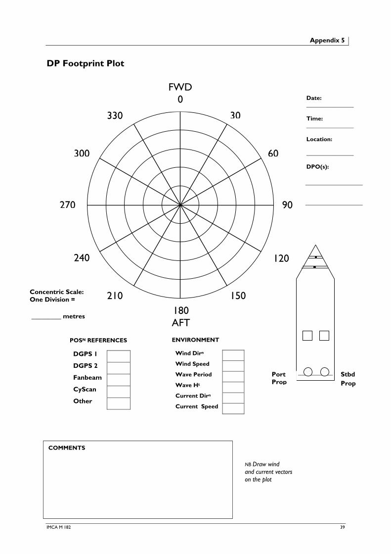
Appendix 5
DP Footprint Plot
FWD 0
180 AFT
210
240
270
150
120
300 60
30
90
330
Date: ________________ Time: ________________ Location: ________________ DPO(s):
POSN REFERENCES DGPS 1
DGPS 2
Fanbeam
CyScan
Other
ENVIRONMENT
Wind Dirn
Wind Speed
Wave Period
Wave Ht
Current Dirn
Current Speed
COMMENTS
NB Draw wind and current vectors on the plot
Concentric Scale: One Division = _________ metres
Port Prop
Stbd Prop
IMCA M 182 39

Guidance on Conducting DP Footprint Plots
A DP footprint plot is designed to record the observed movement of the DP vessel from its desired target location over a period of time. Thruster configuration is selected at the beginning of the plot. The environmental forces of wind and waves are known from visual observation. Current is estimated.
A DP footprint is polar in outline with the bow, head up, at 0 degrees and the desired or target position is at the centre of the circle.
1 Select a safe location away from structures, other vessels, etc.
2 Make entries on the lines in the top right hand corner, identifying when, where and by whom.
3 Indicate in the vessel outline which of the thrusters is selected and on line for the duration of the plot.
4 Complete the environment boxes, putting a value against all of the forces and directions. Draw arrows on the plotting chart to indicate force and direction. Note that values for current should preferably be from an independent current meter. If not available, estimates for current from other appropriate sources include surface current charts and the DP estimated current.
5 Indicate which of the position references are on line for the duration of the plot.
6 Select the concentric scale. One division could equal one metre, so that the total scale extends to 5 metres from the centre, or, if more vessel movement is expected, one division could equal 2 metres, hence increasing the total range to 10 metres from the centre.
7 Start plotting by marking with an X at regular intervals, say every 30 seconds, the observed position of the vessel in relation to the target position. The vessel’s position can be taken from the DP system display screen.
8 Continue plotting until sufficient information is gained about the vessel’s position keeping performance in the given environmental conditions. A completed plot will show the accuracy with which the vessel kept position. Plots can also show the occasions when the vessel is unable to keep position, i.e. when there is insufficient thruster force for the given environment. (This is a good check of the relevance of the calculated DP capability plots.)
DP footprint plots should be conducted whenever opportunities arise. Accumulated knowledge of the vessel’s position keeping performance and the expected vessel excursions are helpful when selecting separation distance, critical and allowable excursion limits.
NB A DP footprint is different to a DP capability plot. A DP capability plot shows by calculation maximum environmental conditions in which a DP vessel should not lose position.
Where the facility exists, the vessel’s footprint in DP can be captured by enabling the ‘snail trail’ and then performing a screen dump. It is recommended that this method is used as well as the hard copy DP footprint plot described above.
40 IMCA M 182

Appendix 6
Sample Arrival Checks Document
DP field arrival checks are to be carried out before the vessel comes within 500 metres of the first offshore installation on the voyage. The checks need only to be carried out once per voyage.
The purpose of these checks is to ensure satisfactory operation of the DP system. The checks require full functional checks of the operation of the thrusters, power generation, auto DP and joystick/manual controls. The checks also ensure that the DP system is set up correctly and that the manning is adequate.
Completed checklists should be kept on board the vessel in accordance with the company’s document control procedures.
Notes: Tick or circle YES or NO throughout the checklist. ‘YES’ indicates that the item is operating satisfactorily. An explanation should be given where ‘NO’ is given as an answer. These checks are to carried out by the DPOs on watch, signed and dated.
1 Main Engines
Port Main Engine YES NO Stbd Main Engine YES NO
Both main engines are required for DP class 2.
2 Power Generation
Aux DG 1 YES NO Aux DG 2 YES NO Aux DG 3 YES NO
Two aux DGs are required for DP class 2. Three aux DGs are required when the main crane is to be used. Comment
3 Main Stern Propulsion
Port Z-Drive Thrust YES NO Stbd Z-Drive Thrust YES NO
Port Z-Drive Rotation YES NO Stbd Z-Drive Rotation YES NO
Both z-drives are required for DP class 2. Comment
4 Bow Tunnel Thrusters
BTH 1 YES NO BTH 2 YES NO
Both bow tunnel thrusters are required for DP class 2. Comment
5 Thruster Control
IJS YES NO Manual YES NO
Test IJS and manual thruster controls in all axes to maximum thrust levels. Comment
6 DP Console
OS 1 YES NO OS 2 YES NO
Lamp test and full function test of DP control console Test position and heading movements in auto DP control. Test change over from auto DP to IJS and manual thruster control and back Comment
IMCA M 182 41

7 Position Reference Systems
DGPS 1 YES NO DGPS 2 YES NO DGPS 3 YES NO
Fanbeam YES NO HPR 400 YES NO Other YES NO
Test all PRS individually and in combination. Three PRS are required to be available for DP class 2, two of which are to be independent, e.g. 2 x DGPS plus 1 x Fanbeam or HiPAP is an acceptable combination Comment
8 Gyros
Gyro 1 Gyro 2 Gyro 3
Hdg
YES NO Hdg
YES NO Hdg
YES NO
Record gyro headings Comment
9 Wind Sensors
Anem 1 Anem 2 Speed
Dir’n
YES NO Speed
Dir’n
YES NO
Record wind speed and direction Comment
10 Motion Sensors
MRU 1 MRU 2
Pitch
Roll
YES NO Pitch
Roll
YES NO
Record pitch and roll values Comment
11 Heading and Position Settings
Hdg Wg = º Hdg Alarm = º Pos Wg = m Pos Alarm = m
Comment
12 Consequence Analysis Activated? YES NO
Consequence analyser is required for DP class 2.
13 DP Alarm Printer Active and Clear? YES NO
14 Machinery Alarm Printer Active and Clear? YES NO
Comment
15 Environment
Seastate
Current Speed and Direction
16 Offshore Location
Field Name Water Depth
42 IMCA M 182

17 DP Operators Enter the names of all DPOs who will operate the DP system during the voyage. DPO Name DP Qualification (full or limited)
Signed
Time and Date
Signed
Time and Date
IMCA M 182 43


Appendix 7
Sample DP Watchkeeping Handover Checklist
Time and Date : / / : / / : / /
General
Online computer A B A B A B
Auto-switch on
Consequence analysis Off Class 2 Off Class 2 Off Class 2
Alarm page clear
Vessel mode Auto Pos Follow Sub Auto Pos Follow Sub Auto Pos Follow Sub
Gain Low Med High Low Med High Low Med High
Position setpoint N N N
E E E
Vessel speed m/s m/s m/s
Limits pos/head m ° m ° m °
Rate of turn °/min °/min °/min
Posplot range m m m
References
Selected DGPS1 DGPS2 TW HIPAP DGPS1 DGPS2 TW HIPAP DGPS1 DGPS2 TW HIPAP
HIPAP Pole Up Down Up Down Up Down
Transponder no.s
Deployment
Divers In Out In Out In Out
Others
Follow Target
ROV In Out In Out In Out
TP no./location
Reaction radius m m m
Sensors
Gyros 1 2 3 1 2 3 1 2 3
Wind
Compare
Environment
Wind dir/speed (T) ° kts ° kts ° kts
Current dir/speed (T) ° kts ° kts ° kts
Thrusters
Online 1 2 3 4 5 1 2 3 4 5 1 2 3 4 5
Mode Var. 90/270 Var. 90/270 Var. 90/270
Setpoint/F.back
Rudder zero
Power
Generators online 1 2 3 4 5 6 1 2 3 4 5 6 1 2 3 4 5 6
Available 1 2 3 4 5 6 1 2 3 4 5 6 1 2 3 4 5 6
Clutched in 1 2 3 4 1 2 3 4 1 2 3 4
Available power kW kW kW
Maximum used kW kW kW
Communications
Field
Dive control
ROV
Deck/crane
Others
DPO Signature
IMCA M 182 45


Appendix 8
DP Incident Reporting
Background
IMCA (and its predecessor DPVOA) has been collecting DP incident reports provided by members and publishing them as annual reports since 1991. During this time, the format of the IMCA report has changed little – using the categorisation of ‘Loss of Position 1’ (LOP1) for major loss of position, ‘Loss of Position 2’ (LOP2) for minor loss of position and ‘Lost Time Incident’ (LTI) for downtime as a result of loss of redundancy but where loss of position has not occurred.
The IMCA Marine Division Management Committee reviewed the system in 2005 and concurred that, since the system at that time could be considered to be somewhat subjective and that there could be some confusion as to when an incident should be reported to IMCA or not, it would be better to replace the reporting categories with those set out below. The aim of the change of format is to help people who are reporting incidents to have a better idea whether to report the incident and in which category it would fall and also to help those reading the annual report as it provides a wider range of incident types.
New Categorisations
The following new categories of DP incidents have been proposed and agreed by the IMCA Marine Division Management Committee. These categories should be used in conjunction with the revised IMCA Station Keeping Incident Form. These new categorisations will be used to replace the ‘Loss of Position 1’ and ‘Loss of Position 2’ incident categorisation currently used in the IMCA annual DP incident reports.
1 DP Incident Loss of automatic DP control, loss of position or any other incident which has resulted in or should have resulted in a ‘Red Alert’ status.
2 DP Undesired Event Loss of position keeping stability or other event which is unexpected/uncontrolled and has resulted in or should have resulted in a ‘Yellow Alert’ status.
3 DP Downtime Position keeping problem or loss of redundancy which would not warrant either a ‘Red’ or ‘Yellow’ alert, but where loss of confidence in the DP has resulted in a stand-down from operational status for investigation, rectification, trials, etc.
4 DP Near-Miss Occurrence which has had a detrimental effect on DP performance, reliability or redundancy but has not escalated into ‘DP Incident’, ‘Undesired Event’ or ‘Downtime’, such as: ♦ crane or load interfering with Artemis line of sight; ♦ scintillation.
5 DP Hazard Observation Set of circumstances identified which have had the potential to escalate to ‘Near-Miss’ status or more serious, such as: ♦ Fanbeam laser target being placed in a position on handrails of a busy walkway where heavy traffic
of personnel wearing PPE with retro reflective tape is identified; ♦ crane lift being swung close to Artemis line of sight. This category should also capture relevant occurrences even when not operating in DP mode, such as: ♦ speed and latitude corrections supplied to all gyros from single DGPS by installation engineer; ♦ unexpected loss of essential DP components which would have had the potential to result in ‘DP
Incident’, ‘Undesired Event’ or ‘Downtime’ if vessel had been operating in DP mode.
IMCA M 182 47

Guidance for Completing the IMCA Station Keeping Incident Form
Incident Types:
1 DP incident 2 DP undesired event 3 DP downtime 4 DP near-miss 5 DP hazard observation
♦ Incident types 1 & 2 are likely to result in type 3. Identify the option on the IMCA Station Keeping Incident Form which represents the greatest potential for harm. All sections of the form should be completed.
♦ For incident types 1, 2 & 3, please indicate ‘Initiating Event’, ‘Main Cause’ and ‘Secondary Cause’ where appropriate on the IMCA Station Keeping Incident Form, e.g.:
i) ‘Initiating Event’ – Additional thrust required due to increasing environmental conditions
ii) ‘Main Cause’ – Stoppage of thrusters
iii) ‘Secondary Cause’ – Operator error
♦ Incident types 4 & 5 can be reported to IMCA by e-mail and should only require a short description of events.
DP incident report forms are available from IMCA – www.imca-int.com
48 IMCA M 182