NSUF Partner Facilities Working Group (PFWG) Meeting Meyer INL - NSUF partner 2017 PIE... · NSUF...
24
Overview of Capabilities at INL November 1, 2012 NSUF Partner Facilities Working Group (PFWG) Meeting May 24 & 25, 2017 Mitch Meyer
-
Upload
phungtuyen -
Category
Documents
-
view
212 -
download
0
Transcript of NSUF Partner Facilities Working Group (PFWG) Meeting Meyer INL - NSUF partner 2017 PIE... · NSUF...

Overview of Capabilities at INL
November 1, 2012
NSUF Partner Facilities Working Group (PFWG) Meeting May 24 & 25, 2017
Mitch Meyer
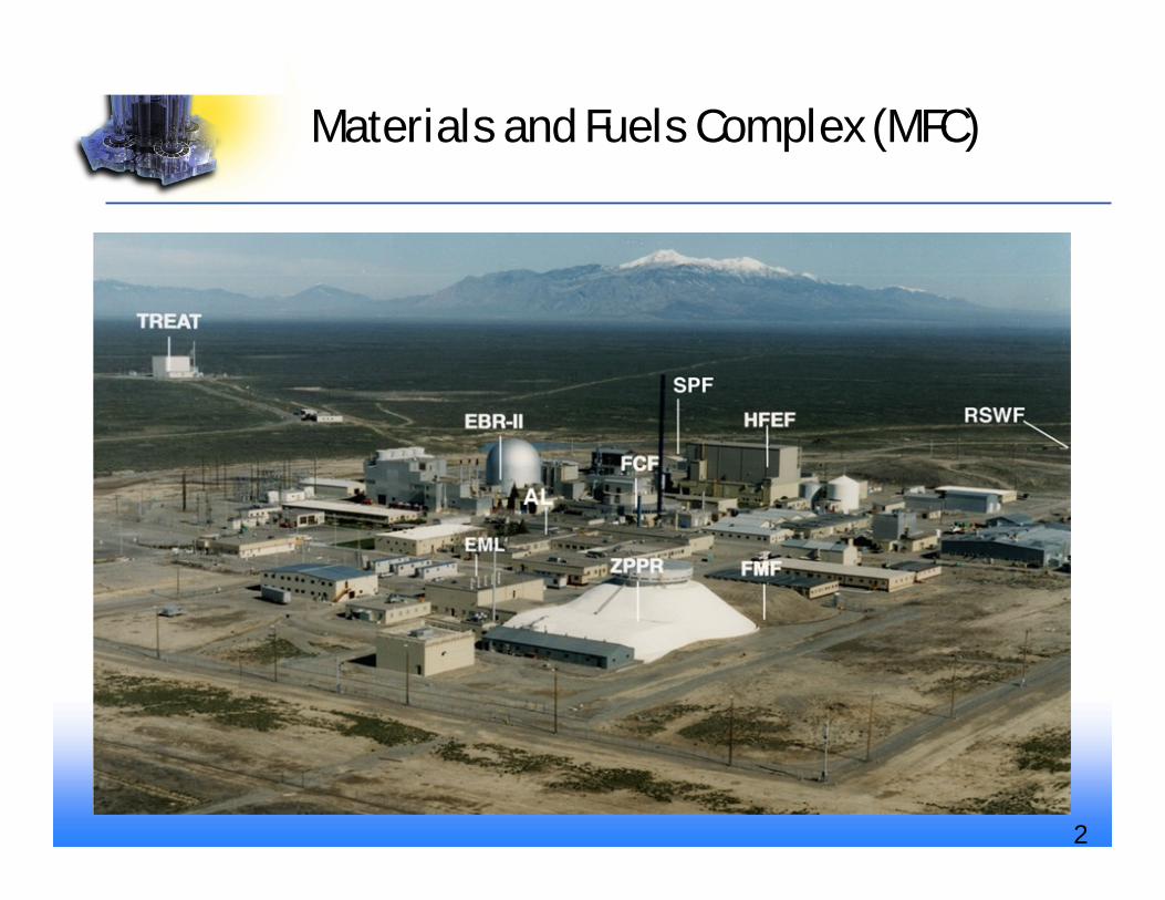
Materials and Fuels Complex (MFC)
2

Hot Fuel Examination Facility (HFEF)
• Large, versatile hot cell facility • Central INL engineering-scale PIE facility • Receipt of irradiated fuels and materials shipments • Disassembly, traditional nondestructive and destructive PIE • HFEF houses NRAD reactor • Large library of materials and fuels
6
Hot Fuel ExaminationFacility: The History in Brief
Purpose and Background
The purpose of this document is to describe for thelayman as well as for the interested industryrepresentative the evolution of the Hot FuelExamination Facility (HFEF) at the Materials andFuels Complex (MFC). Its current capabilities forcharacterizing spent nuclear fuels (SNF),experimental, surveillance and other irradiatedmaterials, are described. Pertinent hot cell systemsare described in detail along with a summary of theircurrent capabilities.
The History
The Hot Fuel Examination Facility was designed in the late 60s, constructed and made operational in the early 70s, to provide support to theLiquid Metal Fast Breeder Reactor community with post- and interim-irradiation examination capabilities. In the following 25 years HFEFhas supported dozens of sponsor organizations, domestic and foreign, in the performance of characterizations of hundreds of fuels andmaterials irradiation experiments.
Major irradiation programs that were supported required the handling of fuels and materials not just from Argonne National Laboratory’sExperimental Breeder Reactor II (EBRII), but also Fast Flux Test Facility, (FFTF), Transient Reactor Test Facility (TREAT), Sodium Loop SafetyFacility (SLSF), Advanced Test Reactor (ATR), Shippingport Light Water Breeder Reactor (LWBR), and most recently the Commercial LightWater Reactor (CLWR), Watts Bar-irradiated materials and Spent Nuclear Fuel Dry Cask Storage characterizations. Literally thousands ofirradiations tests have undergone examinations at HFEF
Since the first post- and interim-examination activities in 1975, HFEF has been upgraded and has evolved into the multi-program facility thatit is today. Major and minor facility modifications have contributed to the array of unique capabilities that HFEF offers to the irradiatedmaterials characterization community.
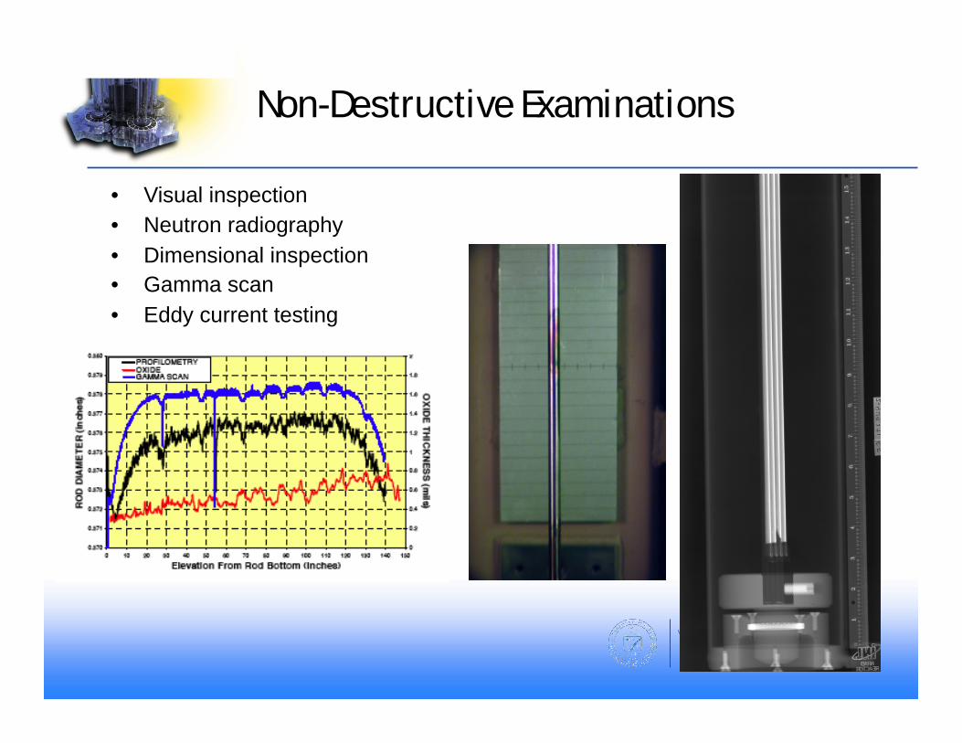
Non-Destructive Examinations
• Visual inspection • Neutron radiography • Dimensional inspection • Gamma scan • Eddy current testing
Destructive Examinations & Testing
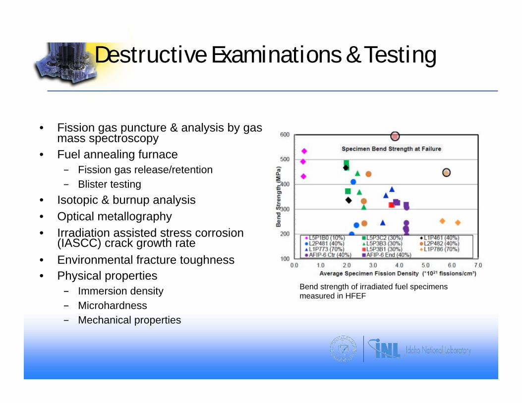
• Fission gas puncture & analysis by gas mass spectroscopy
• Fuel annealing furnace - Fission gas release/retention - Blister testing
• Isotopic & burnup analysis • Optical metallography • Irradiation assisted stress corrosion
(IASCC) crack growth rate • Environmental fracture toughness • Physical properties
- Immersion density - Microhardness - Mechanical properties
Bend strength of irradiated fuel specimens measured in HFEF

Analytical Laboratory (AL) • Analytical chemistry of
irradiated fuels and materials • 6 hot cells configured for
analytical chemistry sample preparation
• Connected to HFEF via pneumatic transfer system
• Wide range of analysis methods including ICP-MS, multi collector ICP-MS, gas mass spectrometry, optical emission systems, and TIMS (Thermal Ion Mass Spectroscopy), CNO
• X-ray diffraction • Unirradiated fuel thermal
property measurements • U, Pu isotopics
!

Thermal Property Measurement
• Differential Scanning Calorimetry - Netzsch DSC 404 - 25-1650°C
• Laser Flash Diffusivity - Netzsch HLFA 427 - 25-2800°C
• Simultaneous Thermal Analyzer (STA) - Netszsch STA 449 - 25-1650°C
• Dilatometer (DIL) - Netszsch DIL 402 PC - 25-1600°C
• U, Pu, TRU capability • Liquid metal and salt
Irradiation Assisted Stress Corrosion Cracking
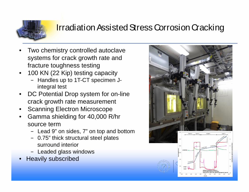
• Two chemistry controlled autoclave systems for crack growth rate and fracture toughness testing
• 100 KN (22 Kip) testing capacity - Handles up to 1T-CT specimen J-
integral test • DC Potential Drop system for on-line
crack growth rate measurement • Scanning Electron Microscope • Gamma shielding for 40,000 R/hr
source term - Lead 9” on sides, 7” on top and bottom - 0.75” thick structural steel plates
surround interior - Leaded glass windows
• Heavily subscribed

Electron Microscopy Laboratory
FEI Quanta Focused Ion Beam (FIB)
JEOL 2010Transmission Electron Microscope (TEM)
Transmission electron microscopy images of unirradiated (a and b)Ti3SiC2 and (c and d) Ti2AlC showing dislocation arrays and stacking faults. He, et al., J. Nucl. Mater. 468 (2016) 194.
Transmission Electron micrograph of phases formed in unirradiated Pu-30Zr alloy and corresponding diffraction patterns of the observed phases. This material is being used as a model system for coupling experiments and simulations. Aitkaliyeva et.al., under preparation, J. Nucl. Mater. (2016).
9
JEOL-7000F FEG-SEM
Capabilities are available for contact handled radiological materials, including transuranics
!

10
Irradiated Materials Characterization Laboratory
• Advanced post-irradiation analysis facility – 12,000 ft2 hazard category 2 nuclear laboratory – HC-2 designation allows analysis of multi-recycle fuel – Designed to house sensitive instrumentation – Initial capability: EPMA, dual beam FIB/SEM (x2), FEG-STEM, thermal analysis &
sample prep – Reconfigurable as instrumentation technology advances or analysis needs change
Shielding and Confinement for Electron Beam Instruments
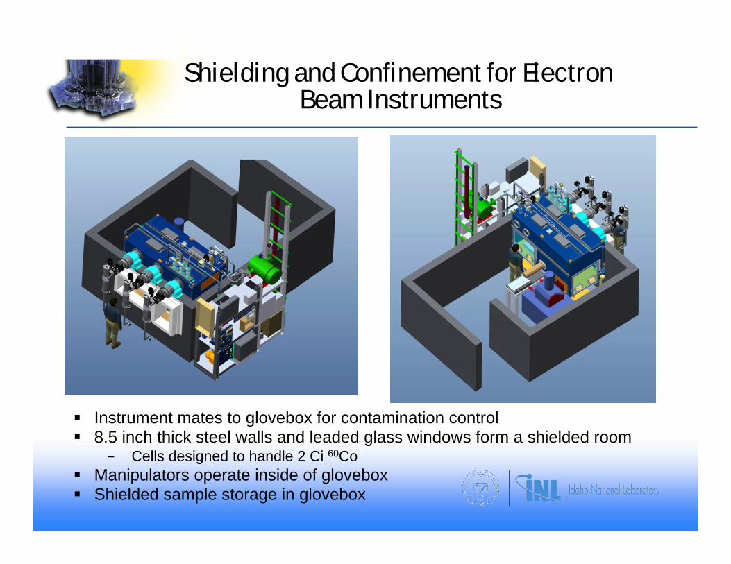
§ Instrument mates to glovebox for contamination control § 8.5 inch thick steel walls and leaded glass windows form a shielded room
- Cells designed to handle 2 Ci 60Co § Manipulators operate inside of glovebox § Shielded sample storage in glovebox

IMCL Instruments
§ Shielded Instruments - Electron Probe MicroAnalysis – CAMECA SX100 R - Dual beam FIB - FEI Quanta 3G - Dual beam FIB - FEI Helios PFIB - Transmission Electron Microscope - FEI Titan 200 ChemiSTEM - Thermal Property Characterization suite (shielded)
§ Unshielded instruments: - JEOL-7600 FEG-SEM (Fall 2017) - X-ray diffraction (Fall 2017)
Helios Plasma FIB
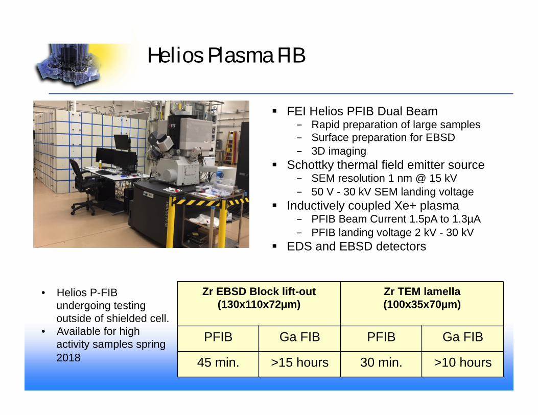
§ FEI Helios PFIB Dual Beam - Rapid preparation of large samples - Surface preparation for EBSD - 3D imaging
§ Schottky thermal field emitter source - SEM resolution 1 nm @ 15 kV - 50 V - 30 kV SEM landing voltage
§ Inductively coupled Xe+ plasma - PFIB Beam Current 1.5pA to 1.3µA - PFIB landing voltage 2 kV - 30 kV
§ EDS and EBSD detectors
Zr EBSD Block lift-out (130x110x72µm)
Zr TEM lamella (100x35x70µm)
PFIB Ga FIB PFIB Ga FIB
45 min. >15 hours 30 min. >10 hours
• Helios P-FIB undergoing testing outside of shielded cell.
• Available for high activity samples spring 2018

• The microstructure of high-burnup uranium-molybdenum monolithic fuel was characterized using scanning electron microscopy (SEM). The fission density of this material is ~9.5x10²¹ f/cm3.
• The micrograph at right shows the extensive network of fission gas (xenon and krypton) bubbles that forms during irradiation. These gases are the primary contributor to the 70% volume swelling exhibited by this fuel.
• It has become apparent that sample preparation using focused ion beam (FIB) techniques is necessary to present an accurate representation of microstructure in these materials.
FIB techniques reveal details about high-burnup microstructure
6 micrometers (millionths of a meter)
Cross section view of U-10Mo fuel with Zr barrier layer on both sides before and after irradiation (top), and the irradiated microstructure at high burnup (bottom).
14

Transmission Electron Microscope
§ FEI Titan Themis 200 ChemiSTEM - Accelerating voltage range of 80 to 200 KV - 0.16 nm resolution - X-FEG high brightness Schottky source - Four windowless silicon drift detectors.
- Very fast data acquisition - Detectors are interlocked to shutters to
shield in case of high gamma dose rate from the specimen.
- Piezo-electric specimen stage with single tilt, low background double tilt high angle single tilt-rotate tomography holders
- On axis bright field, dark field and high angle annular dark field STEM detectors with capability to display multiple image signals simultaneously
- 4k x 4k 16 bit CMOS camera
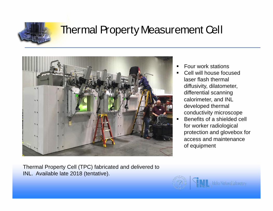
Thermal Property Measurement Cell
§ Four work stations § Cell will house focused
laser flash thermal diffusivity, dilatometer, differential scanning calorimeter, and INL developed thermal conductivity microscope
§ Benefits of a shielded cell for worker radiological protection and glovebox for access and maintenance of equipment
Thermal Property Cell (TPC) fabricated and delivered to INL. Available late 2018 (tentative).
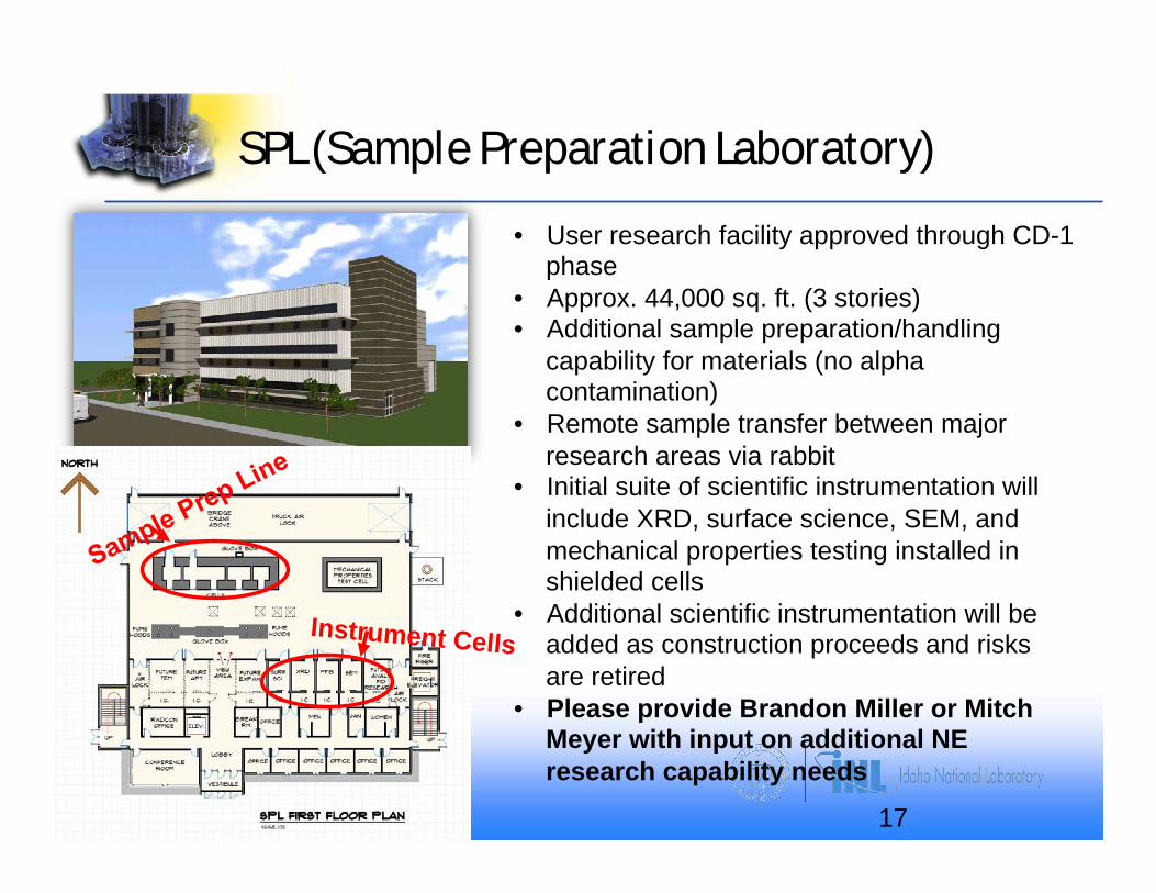
SPL (Sample Preparation Laboratory)
17
Instrument Cells
• User research facility approved through CD-1 phase
• Approx. 44,000 sq. ft. (3 stories) • Additional sample preparation/handling
capability for materials (no alpha contamination)
• Remote sample transfer between major research areas via rabbit
• Initial suite of scientific instrumentation will include XRD, surface science, SEM, and mechanical properties testing installed in shielded cells
• Additional scientific instrumentation will be added as construction proceeds and risks are retired
• Please provide Brandon Miller or Mitch Meyer with input on additional NE research capability needs

Fuel assembly – 3 m Fuel pellet – 1 cm (10-2 )
UO2 grain – 10 µm (10-5)
UO2 grain boundary – 2 nm (10-9)
REVIEW The high burn-up structure in nuclear fuel
DECEMBER 2010 | VOLUME 13 | NUMBER 12 26
of about 0.1 – 0.3 µm. The fission gas is removed from the fuel matrix,
and is retained in a high concentration of micron-sized intergranular
closed pores; reported values for the porosity fraction in the HBS can
exceed 20%6. The microstructure of the subdivided grains appears free
of extended defects. This restructuring (or recrystallization, according to
several authors, see section on formation of HBS) affects a thin region
of the fuel pellet, initially a few µm thick, extending inwards with
increasing burn-up (Fig. 57). The diameter of LWR fuel pellets is of the
order of ~9.6 – 9.7 mm. The HBS structure is also observed in Mixed
U-Pu OXide (MOX) fuel, in Pu-rich islands where fission density and
the corresponding local burn-up exceed the HBS formation threshold.
Additionally, grain subdivision morphology has been reported in U-Mo
alloy fuel8-10 and fast reactor U-Pu oxide, carbide and nitride fuels11-13.
The first observations of this restructuring process were reported in
the late 1950s, mainly in relation to applications for naval reactors14,15,
Fig. 2 Ceramography of a cross-section of an etched LWR UO2 pellet with an average burn-up of ~65 GWd/tHM showing the regions near the pellet rim. (a) Unrestructured fuel at the intermediate radial region; planar defects are visible as dark features within the grains. (b) HBS at the rim of the fuel pellet; at the far right of this image the interface region between fuel and cladding is visible.
(b)(a)
Fig. 3 Transmission Electron Microscopy (TEM) images showing the microstructure of: (a) unrestructured UO2 with 55 GWD/tHM; (b) UO2 with 82 GWd/tHM presenting a typical low-angle subgrains microstructure of HBS2,21. © 2000 American Nuclear Society.
(a)
Fig. 4 High magnification SEM fracture surface micrograph of LWR UO2 fuel with a local burn-up of around 160 GWd/tHM. The image shows in detail the morphology of HBS, characterized by sub-micron grains and micron-sized intergranular pores. Figure reproduced from30.
(b)
MT1312p24_33.indd 26 18/11/2010 10:48:37
Individual atoms – 3 Å (10-10)
Characterization capabilities span 10 orders of magnitude
Scale of Characterization Techniques

Microscopy
§ The history of microscopy has been the pursuit of learning more and
more about less and less. We have now reached the atomic scale in this pursuit.
§ Progress from this juncture will be measured by our ability to learn more information about increasingly greater volumes of materials.
§ The number of interesting materials challenges that can be addressed and the certainty of the information’s veracity grow geometrically as access to larger data structures increases.
§ The future of microscopy will be the pursuit of learning more and more about more and more.
Tom Kelly, Microsc. Microanal. 23, 34-45 (2017)
Idaho National Laboratory

Analytical Instrumentation
2 Multicollector Thermal Ionization Mass Spectrometers (TIMS) 2 Inductively Coupled Plasma – Mass Spectrometers (ICP-MS) 2 Inductively Coupled Plasma – Atomic Emission Spectrometers (ICP-AES) 1 Multi-Collector Inductively Coupled Plasma Mass Spectrometer Ultra Violet/Visible Spectrophotometer X-ray Diffractometer X-Ray Fluorimeter Thermal property measurement Liquid Scintillation Counter Alpha Counters Gamma Spectrometers Digital Scanning Coulometry Gas Mass Spectrometer Gas Chromatogram
21
• Micro-XRD • Electromagnetic Isotope Separator • Electron Probe Micro-analyzer (EPMA)

Shielded Sample Preparation Area (SSPA)
§ Shielded sample preparation cell (right cell) § Optical microscope (left cell) § Sample transfer cell – connectivity to HFEF and other
facilities with IMCL shielded container § Glovebox and hood line for preparation and
decontamination of lower activity samples

Electron Probe Microanalysis
§ Cameca SX100 R electron probe microanalysis system § System is internally shielded to protect electronics and detectors from fields up to
1.1×10¹¹ Bq (3 Ci of 137Cs) § Capable of elemental measurements from boron to curium § Accelerating voltage 5 to 50 kV § Regulated beam current up to 250 nA § Currently available for low-level radiological sample. High activity samples in
October 2017

Dual Beam Focused Ion Beams
FIB shielded cell houses both FEI Quanta and Helios Plasma FIBs
• Quanta FIB mated to containment box inside of shielded cell
• Currently available for low-level radiological materials. Available for high activity samples spring 2018