NSBA Keaschall Case Studies of Girder Erection · methods that are used when erecting steel...
11
Page 1 of 11 CASE STUDIES OF COMPLEX GIRDER ERECTION ANDREW KEASCHALL HOSSAM ABDOU BIOGRAPHY Andrew Keaschall is a graduate of the University of Illinois where he received both his bachelor’s and master’s degrees. After graduation, he joined Alfred Benesch and Company where he is now the Group Manager for the Structural Department. Andrew has worked on several high profile projects including the Wacker Drive Reconstruction in downtown Chicago and a new major bridge that will carry I-74 over the Mississippi River. Andrew also has a leading role in the Construction Engineering practice at Benesch where he assists Contractors in addressing some of their most pressing project challenges. Hossam Abdou is Sr. Vice President and the Chief Structural Engineer at Alfred Benesch and Company. He has practiced structural engineering for more than 27 years. He has a Ph.D. in structural engineering from the University of Michigan in Ann Arbor. Dr. Abdou specializes in the analysis, design and construction of complex bridges. Dr. Abdou initiated the construction engineering practice at Benesch and has extensive experience working with contractors demonstrating the ability to evaluate different construction means and methods based on constructability and cost effectiveness. SUMMARY This paper will discuss four case studies associated with girder erection of complex, long span plate girder bridges. The four bridges are located in four different geographic locations and erected by four different Contractors using four different methods of construction. Each method was selected to address constraints that were unique and specific to each project. This presentation will illustrate the challenges associated with the various methods of plate girder bridge erection and how these challenges were addressed. The first bridge is 1,980 feet long with a main span over the navigation channel of 490’. The Contractor elected to use strand jacking in order to minimize impacts to channel navigation below. The second bridge is 1,600 foot long with 335’ spans and is located in a river with deep water and piers extending well above the water surface. The construction method here involved the use of pier brackets and drop-in segments. The third case study highlights a curved flyover girder structure with span lengths of 250 feet. The presentation will cover methods to address plumbness of the girders during the crane pick and throughout the partially erected phases of the structure. The last case study is for a 2,100 foot long bridge over the Clinch River. The center spans of this structure are 378’ and over deep water. The method of construction for this bridge involved the use of a shoring tower that was mounted on a floating barge. Ballast tanks in the barge were used to address multiple load scenarios encountered during the various stages of erection.
Transcript of NSBA Keaschall Case Studies of Girder Erection · methods that are used when erecting steel...

Page 1 of 11
CASE STUDIES OF COMPLEX GIRDER
ERECTION
ANDREW KEASCHALL
HOSSAM ABDOU
BIOGRAPHY
Andrew Keaschall is a graduate of the University of Illinois where he received both his bachelor’s and master’s degrees. After graduation, he joined Alfred Benesch and Company where he is now the Group Manager for the Structural Department. Andrew has worked on several high profile projects including the Wacker Drive Reconstruction in downtown Chicago and a new major bridge that will carry I-74 over the Mississippi River. Andrew also has a leading role in the Construction Engineering practice at Benesch where he assists Contractors in addressing some of their most pressing project challenges.
Hossam Abdou is Sr. Vice President and the Chief Structural Engineer at Alfred Benesch and Company. He has practiced structural engineering for more than 27 years. He has a Ph.D. in structural engineering from the University of Michigan in Ann Arbor. Dr. Abdou specializes in the analysis, design and construction of complex bridges. Dr. Abdou initiated the construction engineering practice at Benesch and has extensive experience working with contractors demonstrating the ability to evaluate different construction means and methods based on constructability and cost effectiveness.
SUMMARY
This paper will discuss four case studies associated with girder erection of complex, long span plate girder bridges. The four bridges are located in four different geographic locations and erected by four different
Contractors using four different methods of construction. Each method was selected to address constraints that were unique and specific to each project. This presentation will illustrate the challenges associated with the various methods of plate girder bridge erection and how these challenges were addressed.
The first bridge is 1,980 feet long with a main span over the navigation channel of 490’. The Contractor elected to use strand jacking in order to minimize impacts to channel navigation below. The second bridge is 1,600 foot long with 335’ spans and is located in a river with deep water and piers extending well above the water surface. The construction method here involved the use of pier brackets and drop-in segments.
The third case study highlights a curved flyover girder structure with span lengths of 250 feet. The presentation will cover methods to address plumbness of the girders during the crane pick and throughout the partially erected phases of the structure. The last case study is for a 2,100 foot long bridge over the Clinch River. The center spans of this structure are 378’ and over deep water. The method of construction for this bridge involved the use of a shoring tower that was mounted on a floating barge. Ballast tanks in the barge were used to address multiple load scenarios encountered during the various stages of erection.

Page 2 of 11
CASE STUDIES OF COMPLEX GIRDER ERECTION
Introduction
It is no secret among structural engineers that steel bridges are in their most vulnerable state when they are being erected. A finished bridge enjoys the benefits of fully connected cross frames, and splices in addition to a rigid concrete deck. These elements provide redundancy and an overall capacity that is typically much greater than what conventional analysis methods predict. When a bridge is being constructed, the structural configuration of the bridge is constantly changing, and each stage must be analyzed to assess the structural stability and integrity. Long span, heavily skewed, and curved bridges make these temporary states of partial completion even more challenging. This paper will discuss four case studies where various methods of construction were used to erect bridges in four different locations, and by four different contractors. The purpose of this paper is not to go into great detail regarding any individual method of construction, but rather to illustrate a variety of different methods that are used when erecting steel I-girders, and how these methods were analyzed the approach to match the Contractor’s scheme.
I-270 Over the Chain of Rocks Canal
Project Details:
This structure consists of 10 girder lines with a total length of 1,980 feet including a main span of 490’ which carries I-270 over the navigation channel of the Chain of Rocks Canal. The Canal is a Mississippi River bypass route located at a bend in the River near St. Louis. The girder depths vary along the length of the structure with a maximum depth of 13’-3” at the piers adjacent to the navigation channel. In addition to the overall length and magnitude of the bridge, the main challenge during girder erection was to accommodate the Coast Guard requirement that
the navigation channel cannot be closed for more than 24 hours.
Approach Span Erection:
For the four approach spans leading up to the canal (two on each side), the contractor elected to use shoring towers to reduce the effective span length and use “conventional” erection methods. The challenge associated with the shoring towers was to accurately set the top elevation of the tower in order to accommodate both making the splices and then the deflection at the time of release. If the towers were too tall challenges would occur at the splice plates due to improper alignment of the webs. Figure 1 below illustrates how a shoring tower that is too high relative to the trailing tower would create a challenge for making the web splices. A top elevation that is too low, simply creates a scenario where the next support could be “too high”
Figure 1: Illustration of fit-up challenge at splice plate if shoring tower on the right is too high.
Release of the shoring towers was also a challenge due to the magnitude of girder deflections. In the spans adjacent to the main span, up to 21 inches of deflection had to be accounted for at the time of tower release. This required bolsters and special jacking details to facilitate lowering of the structure to release the tower. Figure 2 provides an illustration of the shoring towers used on the project.

Page 3 of 11
Figure 2: Shoring tower used for girder erection for approach spans on I-270 over the Chain of Rocks.
Navigation Span Erection:
In order to meet the limitations on closing the navigation channel to marine traffic, the contractor decided to pre-assemble the main span girder segments on a barge near the shore. The cross section was composed of 10 girder lines and the pre-assembled main span section consisted of 3 segments fully spliced together with a total length of 370 feet. The decision was made to lift two sections, each four girders wide (with a weight of 1.6 million pounds) and a center section which would only be two girder segments wide.
The two girder segment had to be analyzed for global buckling during the strand jacking lift. LUSAS finite element software was used to assess the stability of this section in this scenario. The initial factor of safety against buckling was found to be only 1.21 which the team was not comfortable with. Top lateral bracing was added which modified the buckling shape and increased the factor of safety to 4.3 (See Figure 3).
Figure 3 (below): Two girder buckling analysis showing the improved performance when the top
lateral bracing was installed.
Page 4 of 11
The strand jacking operation itself was to be conducted from the top of the previously erected girders on either side of the navigation channel. Strongback jacking beams were erected on each side as shown in figure 4 below. When erecting drop-in segments, it is important to check the length of the opening between the upper girders against the overall length of the pre-assembled girder below. Girder deflection and rotation along with chamfered web ends can contribute to conflicts if this is not taken into consideration.
Figure 4 illustrates plan details and a photo of the strand jacking assembly. High strength (270 ksi) post-tensioning strands were used to lift the girders from the barge nearly 60 feet below and make the connections at each end of the previously erected girders. Each strand lift took only one day and all Coast Guard requirements were met.
Figure 4: (Upper) Plan details showing strongback jacking beam and (lower) Strand jacks
ready to lift the segments below.
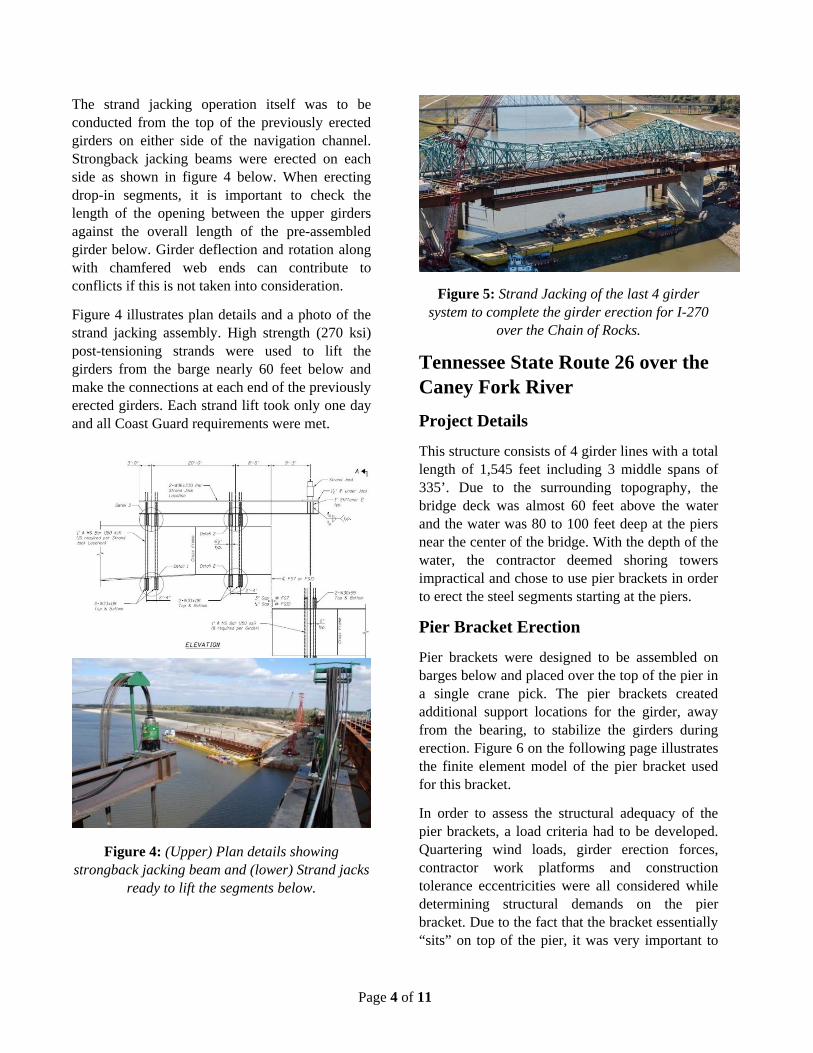
Figure 5: Strand Jacking of the last 4 girder system to complete the girder erection for I-270
over the Chain of Rocks.
Tennessee State Route 26 over the Caney Fork River
Project Details
This structure consists of 4 girder lines with a total length of 1,545 feet including 3 middle spans of 335’. Due to the surrounding topography, the bridge deck was almost 60 feet above the water and the water was 80 to 100 feet deep at the piers near the center of the bridge. With the depth of the water, the contractor deemed shoring towers impractical and chose to use pier brackets in order to erect the steel segments starting at the piers.
Pier Bracket Erection
Pier brackets were designed to be assembled on barges below and placed over the top of the pier in a single crane pick. The pier brackets created additional support locations for the girder, away from the bearing, to stabilize the girders during erection. Figure 6 on the following page illustrates the finite element model of the pier bracket used for this bracket.
In order to assess the structural adequacy of the pier brackets, a load criteria had to be developed. Quartering wind loads, girder erection forces, contractor work platforms and construction tolerance eccentricities were all considered while determining structural demands on the pier bracket. Due to the fact that the bracket essentially “sits” on top of the pier, it was very important to

Page 5 of 11
ensure the support conditions in the finite element model matched up with the structural behavior that would be expected in the field. Because the first girder would be erected as a single segment, pipe braces were used to achieve temporary stability while also providing resistance for a variety of different wind loading conditions.
Figure 6: Finite Element model of pier bracket.
Figure 7: Photo showing girder installation with the pier bracket in place.
After erecting all of the pier segments at piers 2 and 3, the midspan segments were pre-assembled on a barge below. The 200’ midspan segments (in tandem), were lifted via two cranes and spliced to the previously erected pier segments. During this operation, it was important to specify when the supports at the pier brackets must be released and the bolsters removed. This step had to happen so that the pier brackets did not take substantial load when the recently erected girders deflect in the new configuration.
After span 3 was erected, a pier bracket was relocated to pier 4. The process was then to be repeated at pier 4, with the midspan segments of span 4 being dropped in. The structural behavior was different in this situation as continuity had an impact on the girder deflections and rotations. The first tandem of midspan segments in span 4 were erected by connecting the upward deflected “high” splice first (near span 3) and then lowering the other end into place to connect to the girders on pier 4.
Figure 8: Erection of the first two girder segments of span.
After the first pair of span 4 midspan girders were erected, the second pair would have to be installed while accommodating the deflections of the previously erected segments. Figure 9 illustrates the deflected shape of the girder system prior to the second pair of span 4 girder segments being erected. For this step, the splices had to be made in a specific order, with reductions in crane load occurring after each splice was made in order to facilitate fit-up. After the splices adjacent to pier 3 were made, the crane near pier 3 released its load to allow the crane near pier 4 to control the location of the other end of the girder.

Page 6 of 11
Figure 9: (Left) Amplified deflected shape showing span 3 and two girders of span 4 erected. (Right) Deflections (inches) at the ends of the previously erected segments prior to placement of the girders in span 4.
During construction, it was determined that the pier bracket at pier 1 would have to support an unbalanced load in order to meet the schedule. The design and details of the pier bracket were retrofitted to be able to handle the unbalanced load scenario. Tie-downs were anchored into the pier in order to support the uplift that would occur when a segment was spliced to one end of the pier segments. Figure 10 shows the anchorage detail for the pier bracket and a photo of the unbalanced condition.
Figure 10: (Top) Plan details showing the anchorage to the pier cap. (Bottom) Unbalanced girder configuration at pier 1.
Elgin O’Hare Western Access Flyover Ramps
Project Details
This structure consists of a superelevated flyover ramp with a length of 2,100 feet and a 6 girder cross section. The structure consists of 3 units, two of which are curved, and span lengths of 245 feet. The challenges associated with the erection of this structure are primarily associated with handling curvature and torsional deformations associated with the 8’-3” deep I shaped plate girders.
Single Girder Erection
Due to the weight of the girders and crane availability, the girder segments were erected one at a time instead of in pairs, which is more typical of curved girder erection. The first girder segment to be erected was braced at two support points and a hold crane was maintained for stability prior to completing a second girder to create a stable configuration.
After all 6 girder lines were erected to the first splice, the next girder segment would extend from the shoring tower to the pier. The contractor was not going to modify the length of the spreader beam for each girder segment, so some “roll” was going to have to be accommodated in each pick. It was decided to use a spreader beam that was shorter than the ideal length such that the “roll”

Page 7 of 11
during the pick would always be inward. A rigging adjustment detail was developed to allow the ironworkers to apply a restoring moment to the girder that would create a “plumb” girder and facilitate making the splices. Figure 11 shows the plan detail of the rigging adjustment detail, and figure 12 shows a photo of its use in the field.
Figure 11 (Below): Details of rigging adjustment detail used to maintain girder plumbness during the pick.
Figure 12: Photo of the rigging adjustment detail in the field
Another factor to consider when erecting curved girder structures is the order the girders are erected. Due to staging constraints in one span, the contractor was forced to start with girder 3 and erect toward the outer girders before returning to erect girders 1 and 2 (the inside girders). After girders 3, 4 and 5 were erected, the girder system was “rolling” such that girders 4 and 5 were deflected incrementally more than girder 3 (as to be expected and shown in figure 13). When girder 6 was brought in, cross frame fit-up was difficult as the crane supported girder 6 was not able to fit-up properly with the cross frames attached to girder 5 (See figure 14). In order to accommodate the fit-up challenges, the cross frames near the supports, where there is not significant differential deflection, were made first. As stability was achieved via cross frame connections, the crane was able to gradually release load, allowing girder 6 to deflect and the midspan cross frames to be connected.
Figure 13: Finite element model of the deflected shape with girder lines 3, 4 and 5 erected. Deflections are shown in feet.

Page 8 of 11
Figure 14: Illustration (drawn to scale) showing the fit-up challenges of the outside girder relative to previously erected inside girders.
Tennessee State Route 33 over the Clinch River
Project Details:
This structure consists of a 4 girder cross section with a continuous length of 2,100 feet and several spans over water with a length of 378 feet. The body of water below was non-navigable, but the water was 70 to 80 feet deep and shoring towers were not practical. The contractor’s initial plan was to use multiple cranes, some serving as hold cranes, in an attempt to erect girder segments from one pier to the next in a continuous work period. Two girder tandem segments would be pre-erected on barges below in an effort to prepare for the process of getting from one pier to the next.
Shoring Towers in Water
While erecting the approach spans, it became clear that the initial plan to go from one pier to the next in a continuous work period would not work. The deep girders had splices with several hundred bolts and production rates simply wouldn’t allow for making enough splices to get from one span to the next. The idea was broached that if a crane on a barge could support girders as a hold crane, then shoring towers placed on a barge should serve the same purpose.
Placing shoring towers on a barge requires several different variables to be assessed. The initial structural evaluation is feasibility. For this particular erection plan, the largest total load on the shoring tower would be about 400 kips. To
achieve this much displacement, six 10x40’ sectional barges would require 3’ of draft in order to support the loads. This barge configuration was available to the contractor so the next step was to evaluate the staged loading conditions. With a 4 girder cross section, there were 8 stages of various load configurations on the tower. Four individual girders coming into the tower created four different loading scenarios and four separate load configurations were created when the next segment was erected.
The controlling unbalanced load case is illustrated in Figure 15. This condition would create a “listing” moment of 1,700 kip feet. This unbalanced load condition would result in a 2.2% list which was not acceptable for the 40 foot tall shoring tower. The second order effects of the load would create instabilities and lateral forces that could not practically be resisted on a barge.
Figure 15: Finite element model showing girder reactions for 3 girder lines erected. The shoring
tower is represented by the supports in the middle.
In order to mitigate the listing moment, the contractor was able to use barges with ballast compartments. This would allow for some control of the centroid of the weight within the barge and create the opportunity to provide a resisting moment to the unbalanced load associated with the girder configuration. With the ballast tanks, the barge could remain level throughout the various stages of erection and stability could be maintained. Figure 16 illustrates the load condition

Page 9 of 11
on the girders as well as the ballast configuration in the barges for the critical listing moment in the erection procedure.
Figure 16: Illustration showing girder reactions and ballast tank configuration at the controlling
unbalanced load.
Due to the relative uncertainty associated with using a barge mounted shoring tower to support a partially erected structure, two extreme event load cases were checked. The first load case was the event of a sinking barge. For this analysis, the shoring tower supports were simply removed from the model. The results were analyzed to determine stresses and deflections. While the downward deflections at the end were substantial, the stresses in the girder segments remained elastic and therefore the girders would have been recoverable in the event of a sinking barge.
The next extreme event load case was that of a flash flood. The topography in Tennessee is such that the water elevations in these areas can change dramatically with large rainfall events. The total displacement of the sectional barge system was about 750,000 lbs. In order to model this scenario, an applied force of 750 kips in the upward deflection was applied to the girder system at the location of the shoring tower. This would be the force required to “hold” the barges underwater until the water level subsided. For this load case, the upward deflection was over 5’, but the girders again remained elastic (See figure 17). This load
case was the controlling extreme event situation and, the girder displacement, coupled with the draft of the barges indicated that it would take a water level rise of almost 8 feet in order for this to occur.
The last step prior to implementing the erection plan was to establish protocol for maintaining a level barge deck during each stage of erection. This was controlled through field survey and the ballast tanks. This process was first used near the shore, where spud piles could be engaged if required and the contractor was able to successfully monitor the list.
Figure 17: Deflected shape showing contour plots for the girder system at the extreme event limit
state associated with flash flooding to submerge the barge

Page 10 of 11
Figure 18: Photos of barge mounted shoring tower
Conclusion
When constructing structural steel bridges, there are a myriad of different means and methods to erect the girders. Each bridge is unique and has its own unique challenges that have to be addressed. Long span bridges and curved girder structures must be looked at to find potential challenges that may not be evident on shorter or smaller bridges. The structural engineer responsible for the erection plan will often have to develop design criteria that are specific to that particular project and the method of construction that the contractor wishes to employ. The challenges of maintaining structural stability and facilitating an efficient erection plan must be respected and understood in order to develop a successful erection plan.
Acknowledgements
Illinois Department of Transportation
Illinois State Toll Highway Authority
Tennessee Department of Transportation
HDR Engineering
Walsh Construction
Massman Construction
Area Equipment Inc.
Kay and Kay Construction

Page 11 of 11
References
1) AASHTO LRFD Bridge Design Specifications 5th Edition, 2010. American Association of State Highway and Transportation Officials, Washington D.C.
2) Illinois Department of Transportation (IDOT) Bridge Manual, IDOT Bureau of Bridges and Structures, Springfield, IL.
3) AASHTO Guide Design Specifications for Bridge Temporary Works, 1st edition, 2008. American Association of State Highway and Transportation Officials, Washington D.C.
4) Yura, J., Helwig, T., Herman, R., and Zhou, C. (2008). Global Lateral Buckling of I-Shaped Girder Systems.” J. Struct. Eng