NS125 Specification for Low Voltage Overhead Mains€¦ · obtain authorisation from the Network...
32
NW000-S0070 UNCONTROLLED IF PRINTED Page 1 of 32 Network Standard NETWORK Document No Amendment No Approved By Approval Date Review Date : : : : : NW000-S0070 2 Head of AEP & S 01/12/2015 31/03/2019 (Review Date Changed - 06.02.2019) NW000-S0070 NS125 CONSTRUCTION OF LOW VOLTAGE OVERHEAD MAINS
Transcript of NS125 Specification for Low Voltage Overhead Mains€¦ · obtain authorisation from the Network...

NW000-S0070 UNCONTROLLED IF PRINTED Page 1 of 32
Network Standard
NETWORK
Document No Amendment No Approved By Approval Date Review Date
: : : : :
NW000-S0070 2 Head of AEP & S 01/12/2015 31/03/2019
(Review Date Changed - 06.02.2019)
NW000-S0070 NS125 CONSTRUCTION OF LOW VOLTAGE OVERHEAD MAINS

NS125 Construction of Low Voltage Overhead Mains Amendment No 2
NW000-S0070 UNCONTROLLED IF PRINTED Page 2 of 32
ISSUE
For issue to all Ausgrid and Accredited Service Providers’ staff involved with the construction of low voltage overhead lines, and is for reference by field, technical and engineering staff.
Ausgrid maintains a copy of this and other Network Standards together with updates and amendments on www.ausgrid.com.au.
Where this standard is issued as a controlled document replacing an earlier edition, remove and destroy the superseded document.
DISCLAIMER
As Ausgrid’s standards are subject to ongoing review, the information contained in this document may be amended by Ausgrid at any time. It is possible that conflict may exist between standard documents. In this event, the most recent standard shall prevail.
This document has been developed using information available from field and other sources and is suitable for most situations encountered in Ausgrid. Particular conditions, projects or localities may require special or different practices. It is the responsibility of the local manager, supervisor, assured quality contractor and the individuals involved to make sure that a safe system of work is employed and that statutory requirements are met.
Ausgrid disclaims any and all liability to any person or persons for any procedure, process or any other thing done or not done, as a result of this Standard.
All design work, and the associated supply of materials and equipment, must be undertaken in accordance with and consideration of relevant legislative and regulatory requirements, latest revision of Ausgrid’s Network Standards and specifications and Australian Standards. Designs submitted shall be declared as fit for purpose. Where the designer wishes to include a variation to a network standard or an alternative material or equipment to that currently approved the designer must obtain authorisation from the Network Standard owner before incorporating a variation to a Network Standard in a design.
External designers including those authorised as Accredited Service Providers will seek approval through the approved process as outlined in NS181 Approval of Materials and Equipment and Network Standard Variations. Seeking approval will ensure Network Standards are appropriately updated and that a consistent interpretation of the legislative framework is employed.
Notes: 1. Compliance with this Network Standard does not automatically satisfy the requirements of a Designer Safety Report. The designer must comply with the provisions of the Workplace Health and Safety Regulation 2011 (NSW - Part 6.2 Duties of designer of structure and person who commissions construction work) which requires the designer to provide a written safety report to the person who commissioned the design. This report must be provided to Ausgrid in all instances, including where the design was commissioned by or on behalf of a person who proposes to connect premises to Ausgrid’s network, and will form part of the Designer Safety Report which must also be presented to Ausgrid. Further information is provided in Network Standard (NS) 212 Integrated Support Requirements for Ausgrid Network Assets.
2. Where the procedural requirements of this document conflict with contestable project procedures, the contestable project procedures shall take precedent for the whole project or part thereof which is classified as contestable. Any external contact with Ausgrid for contestable works projects is to be made via the Ausgrid officer responsible for facilitating the contestable project. The Contestable Ausgrid officer will liaise with Ausgrid internal departments and specialists as necessary to fulfil the requirements of this standard. All other technical aspects of this document which are not procedural in nature shall apply to contestable works projects.
INTERPRETATION
In the event that any user of this Standard considers that any of its provisions is uncertain, ambiguous or otherwise in need of interpretation, the user should request Ausgrid to clarify the provision. Ausgrid’s interpretation shall then apply as though it was included in the Standard, and is final and binding. No correspondence will be entered into with any person disputing the meaning of the provision published in the Standard or the accuracy of Ausgrid’s interpretation.
KEYPOINTS
This standard has a summary of content labelled “KEYPOINTS FOR THIS STANDARD”. The inclusion or omission of items in this summary does not signify any specific importance or criticality to the items described. It is meant to simply provide the reader with a quick assessment of some of the major issues addressed by the standard. To fully appreciate the content and the requirements of the standard it must be read in its entirety.
AMENDMENTS TO THIS STANDARD
Where there are changes to this standard from the previously approved version, any previous shading is removed and the newly affected paragraphs are shaded with a grey background. Where the document changes exceed 25% of the document content, any grey background in the document is to be removed and the following words should be shown below the title block on the right hand side of the page in bold and italic, for example, Supersedes – document details (for example, “Supersedes Document Type (Category) Document No. Amendment No.”).

KEY POINTS OF THIS STANDARD
NW000-S0070 UNCONTROLLED IF PRINTED Page 3 of 32
Design Fittings and construction Other Scope and risks addressed
Tools and Forms Annexure A – Stockcodes
Annexure B – Construction Drawings
Tools and Forms Annexure B – LV ABC Checklist
Annexure C – Sample Compliance Checklist
This network standard describes the minimum requirements that Ausgrid has adopted for Low Voltage Overhead construction within its franchise. This standard is limited to the scope identified below and provides controls for associated risks as listed below:
Applies to all new LV overhead mains construction within Ausgrid’s Network.
Refer to NS220 Overhead Design Manual for overhead design requirements
Refer to NS124 Specifications for Overhead Service Connections up to 400 Amps for the requirements of low voltage overhead services
Where to for more information? Section 1, 2
Designs shall be done in accordance with NS220 Overhead Design Manual.
Selection of LVABC or bare mains will depend on the project.
Ausgrid will specify rating of all cable required for new construction.
Standard bare conductor sizes and LV ABC conductor sizes listed.
References to clearances are identified.
Façade mounted LVABC is not permitted.
General construction requirements for overhead lines include:
Importance of maintaining the integrity of LVABC insulation.
LVABC fittings described. Use of either paying-out or pulling-in
method to erect cable Pulling tension for LV ABC must not
exceed 4kN Techniques required for securing cable
to intermediate supports Avoiding tension jointing mid-span Vertical bonding requirements Phasing arrangements and standard
phase conductor location Refer to NS127 Specifications for Low
Voltage Cable Joints and Terminations for LV UGOH installation requirements
Requirements for erecting LV ABC through trees or near obstructions
Staying of poles with unbalanced loads Railway and waterway crossings Prevention of conductor clashing
Some specific requirements include:
Use of LV Suspended Services Construction of LV isolating points
using insulated fuse/link switch disconnectors
Maintenance and replacement of legacy assets including asset relocation.
Compliance with Ausgrid Electrical Safety Rules
Live Line work by authorised personnel
Use of approved products NS181 Approval of Materials and
Equipment and Network Standard Variations for procedure applying to approval for alternative products
Tools and Forms none
Where to for more information? Section 5, 6, 7
Where to for more information? Section 8 - 10
Where to for more information? Section 10 - 12

NS125 Construction of Low Voltage Overhead Mains Amendment No 2
NW000-S0070 UNCONTROLLED IF PRINTED Page 4 of 32
Network Standard NS125
Construction of Low Voltage Overhead Mains
Contents 1.0 PURPOSE ............................................................................................................................................. 8
2.0 SCOPE .................................................................................................................................................. 8
3.0 REFERENCES ...................................................................................................................................... 8 3.1 General....................................................................................................................................... 8 3.2 Ausgrid documents .................................................................................................................... 8 3.3 Other standards and documents ................................................................................................ 9 3.4 Acts and regulations ................................................................................................................... 9
4.0 DEFINITIONS ........................................................................................................................................ 9
5.0 DESIGN ............................................................................................................................................... 10 5.1 General..................................................................................................................................... 10 5.2 Selection of conductors ............................................................................................................ 10
6.0 CABLES ............................................................................................................................................... 11 6.1 Bare conductors ....................................................................................................................... 11 6.2 Low Voltage Aerial Bundled Cable (LV ABC) .......................................................................... 11 6.3 LV ABC stringing tension ......................................................................................................... 12 6.4 Façade-mounted aerial bundled cable ..................................................................................... 12
7.0 CLEARANCE CRITERIA ..................................................................................................................... 13 7.1 Ground and structure clearances ............................................................................................. 13 7.2 Vegetation clearances.............................................................................................................. 13
8.0 LV ABC IDENTIFICATION AND CONNECTION ................................................................................ 14 8.1 Identification ............................................................................................................................. 14 8.2 Connection ............................................................................................................................... 14 8.3 Insulation re-establishment ...................................................................................................... 14
9.0 LV ABC FITTINGS ............................................................................................................................... 14
10.0 CONSTRUCTION ................................................................................................................................ 18 10.1 Cable erection .......................................................................................................................... 18
10.1.1 Cable installation by paying-out ................................................................................... 18 10.1.2 Cable installation by pulling-in ...................................................................................... 18
10.2 Intermediate supports .............................................................................................................. 18 10.3 Midspan joints .......................................................................................................................... 18 10.4 Vertical bonding ....................................................................................................................... 18
10.4.1 Vertical bonding for bare conductors ........................................................................... 18 10.4.2 Vertical bonding for LV ABC ........................................................................................ 18
10.5 Phasing/arrangement of conductors ........................................................................................ 18 10.6 Prevention of conductor clashing ............................................................................................. 19 10.7 Multiple LV ABC circuits ........................................................................................................... 19 10.8 Underground to overhead connections (UGOH) ..................................................................... 19 10.9 Erecting ABC through trees or near obstructions .................................................................... 19 10.10 Staying of poles with unbalanced loads ................................................................................... 20
10.10.1 General .................................................................................................................... 20 10.10.2 Stay crossarms ........................................................................................................ 20
NS125 Construction of Low Voltage Overhead Mains Amendment No 2
NW000-S0070 UNCONTROLLED IF PRINTED Page 5 of 32
10.11 Stainless steel bolts and set-screws – lubrication of threads .................................................. 20 10.12 Like-for-like replacements ........................................................................................................ 20 10.13 LV suspended services ............................................................................................................ 20 10.14 Rail crossings ........................................................................................................................... 21 10.15 Waterway crossings ................................................................................................................. 21
11.0 FUSE/LINK SWITCH DISCONNECTORS .......................................................................................... 22 11.1 General..................................................................................................................................... 22 11.2 Installation of insulated fuse/link switch disconnectors ............................................................ 22
12.0 MAINTENANCE AND REPLACEMENT OF LEGACY ASSETS ......................................................... 23 12.1 General..................................................................................................................................... 23 12.2 Summary of content of Drawing No. 234378 ........................................................................... 23
13.0 STORES AND MATERIALS ................................................................................................................ 24
14.0 RECORDKEEPING ............................................................................................................................. 24
15.0 AUTHORITIES AND RESPONSIBILITIES .......................................................................................... 24 15.1 Ausgrid ..................................................................................................................................... 24 15.2 Accredited Service Provider (ASP) .......................................................................................... 24
16.0 DOCUMENT CONTROL...................................................................................................................... 25
ANNEXURE A – STOCKCODES .................................................................................................................... 26
TABLE A1 – STOCKCODES ........................................................................................................................... 26
ANNEXURE B – POLE TOP CONSTRUCTION DRAWINGS ........................................................................ 28
TABLE B1 - LV ABC CONSTRUCTION DRAWINGS ..................................................................................... 28
TABLE B2 – BARE OVERHEAD CONSTRUCTION DRAWINGS .................................................................. 28
TABLE B3 – TWIN AND TWIST DRAWINGS ................................................................................................. 29
TABLE B4 - LV ABC PIERCING CONNECTION ............................................................................................ 29
ANNEXURE C – LV ABC CHECKLIST ........................................................................................................... 30
ANNEXURE D – SAMPLE COMPLIANCE CHECKLIST ................................................................................ 31
NS125 Construction of Low Voltage Overhead Mains Amendment No 2
NW000-S0070 UNCONTROLLED IF PRINTED Page 6 of 32
31

NS125 Construction of Low Voltage Overhead Mains Amendment No 2
NW000-S0070 UNCONTROLLED IF PRINTED Page 7 of 32

NS125 Construction of Low Voltage Overhead Mains Amendment No 2
NW000-S0070 UNCONTROLLED IF PRINTED Page 8 of 32
1.0 PURPOSE This Network Standard describes the minimum requirements that Ausgrid has adopted for Low Voltage (LV) overhead construction within its franchise. Ausgrid will make all the necessary design decisions and requirements for the installation of LV overhead conductors.
LV overhead construction shall only be performed by an Accredited Service Provider (ASP) and in accordance with the requirements of ES4 Service Provider Authorisation.
Refer to the Policy for ASP/1 Premises Connections for details of Ausgrid’s overhead and underground mains policy in relation to connections.
The general guidelines for the form of construction for each development shall be determined by Ausgrid and shall be in accordance with the prevailing Policy of the time. The final interpretation and decision as to the type of construction to be used shall be Ausgrid’s notification of the type of construction shall be issued in the preliminary design brief.
2.0 SCOPE This Network Standard applies to all new Low Voltage (LV) overhead construction work within Ausgrid’s Network. It specifies the materials and construction types to be used. It does not specify the design requirements, which are detailed in NS220 Overhead Design Manual.
This standard does not apply to low voltage overhead services, which are detailed in NS124 Specification for Overhead Connections up to 400 Amps.
3.0 REFERENCES 3.1 General
All work covered in this document shall conform to all relevant Legislation, Standards, Codes of Practice and Network Standards. Current Network Standards are available on Ausgrid’s website at www.ausgrid.com.au.
3.2 Ausgrid documents • Bush Fire Risk Management Plan • Company Form (Governance) - Network Document Endorsement and Approval • Company Procedure (Governance) - Network Document Endorsement and Approval • Company Procedure (Network) - Production / Review of Network Standards • Customer Installation Safety Plan • Electrical Safety Rules • Electricity Network Safety Management System Manual • ES4 Service Provider Authorisation • NS104 Specification for Electrical Network Project Design Plans • NS109 Design Standards for Overhead Supply Developments and Distribution Centres • NS124 Specification for Overhead Service Connections up to 400 Amps • NS127 Specification for Low Voltage Cable Joints and Terminations • NS166 Line Inspection • NS181 Approval of Materials and Equipment and Network Standard Variations • NS212 Integrated Support Requirements for Ausgrid Network Assets • NS220 Overhead Design Manual • NS261 Requirement for Design Compliance Framework for Network Standards • Policy for ASP/1 Premises Connections • Public Electrical Safety Awareness Plan • Public Lighting Management Plan • Tree Safety Management Plan

NS125 Construction of Low Voltage Overhead Mains Amendment No 2
NW000-S0070 UNCONTROLLED IF PRINTED Page 9 of 32
3.3 Other standards and documents • AS 1222.1 Steel conductors and stays - Bare overhead - Galvanized (SG/GZ) • AS 1531 Conductors - Bare overhead – Aluminium and aluminium alloy • AS/NZS 3560.1 Electric cables – cross-linked polyethylene insulated - Aerial bundled - for
working voltages up to and including 0.6/1(1.2)kV – Aluminium conductors • AS 3607 Conductors - Bare overhead, aluminium and aluminium alloy - Steel reinforced • AS 3766 Mechanical fittings for low voltages aerial bundled cables • AS/NZS 4396 Connectors – Insulation Piercing – For 0.6/1kV Aerial Bundled Cables • AS 6947 Crossings of Waterways by Electricity Infrastructure • AS/NZS 7000 – Overhead Line Design – Detailed procedures • ENA Doc 001-2008 National Electricity Network Safety Code • ISSC 3 – Guideline for Managing Vegetation near Power Lines • Service and Installation Rules of NSW • Relevant Industry and WorkCover Guides and Codes of Practice
3.4 Acts and regulations • All pertinent Environmental Regulations and Acts • Electricity Safety Act 1945 • Electricity Supply (General) Regulation 2014 (NSW) • Electricity Supply (Safety and Network Management) Regulation 2014 • Electricity Supply (Safety Plans) Regulation 1997 • Electrical (Installation Safety) Regulation 1992 • Work Health and Safety Act 2011 and Regulation 2011
4.0 DEFINITIONS Accredited Service Provider (ASP)
An individual or entity accredited by the NSW Department of Planning and Environment, Energy, Water and Portfolio Strategy Division, in accordance with the Electricity Supply (Safety and Network Management) Regulation 2014 (NSW).
Aerial Bundled Cable (ABC)
A cable system used by Ausgrid for the low voltage overhead distribution system. The low voltage cable system consists of four compacted stranded hard-drawn aluminium conductors individually insulated with black cross-linked polyethylene (XLPE).
Bare Conductor A conductor not provided with insulation rated for the operating voltage of the line.
Customer The customer is defined as the individual or entity presenting to Ausgrid for business dealings related to the connection and supply of electricity.
Business Management System (BMS)
An Ausgrid internal integrated policy and procedure framework that contains the approved version of documents.
Document control Ausgrid employees who work with printed copies of document must check the BMS regularly to monitor version control. Documents are considered “UNCONTROLLED IF PRINTED”, as indicated in the footer.
Façade mounted Is the description used for the mounting of low voltage aerial bundled cable (as low voltage distribution mains) on to a façade of a commercial or retail premises.
High Voltage (HV) Distribution
All mains and apparatus operating at nominal voltages between 1000 V and 33 kV.

NS125 Construction of Low Voltage Overhead Mains Amendment No 2
NW000-S0070 UNCONTROLLED IF PRINTED Page 10 of 32
System
I.R. Meter An electrical device used for measuring insulation resistance (e.g. 500 V I.R. Meter for LV tests and 1000 V I.R. Meter for HV tests).
Low Voltage Distribution System
All mains and apparatus operating at nominal voltages above extra low voltage and up to and including 1000 V.
Network Standard A document, including Network Planning Standards, that describes the Company's minimum requirements for planning, design, construction, maintenance, technical specification, environmental, property and metering activities on the distribution and transmission network. These documents are stored in the Network Category of the BMS repository.
Phasing (Phased) Means a test to determine whether energised conductors of phase A, B, or C in a polyphase system may be satisfactorily connected together.
Review date The review date displayed in the header of the document is the future date for review of a document. The default period is three years from the date of approval however a review may be mandated at any time where a need is identified. Potential needs for a review include changes in legislation, organisational changes, restructures, occurrence of an incident or changes in technology or work practice and/or identification of efficiency improvements.
5.0 DESIGN 5.1 General
All low voltage overhead line design shall be done in accordance with the requirements of NS220 Overhead Design Manual.
5.2 Selection of conductors The design should aim to deliver the most cost effective long-term solution for the network. The choice between bare mains and LV ABC shall be based on the merits of the particular project, and shall include consideration of the following:
• The balance between span length, stringing tension and pole strength.
• The maximum fault loop impedance for LV ABC specified in section 10 of NS109 Design Standards for Overhead Supply Developments and Distribution Centre will limit the length of each distributor.
• The loop impedance as measured at a customer’s switchboard, and compliance with AS4741, to minimise the risk of customer shocks.
• Proximity to the sea or other bodies of salt water, where LV ABC provides superior corrosion performance.
• Vegetation management, noting that while LV ABC reduces the vegetation clearance window, it does not significantly reduce the vegetation maintenance costs. Low voltage spreaders may provide adequate mitigation of LV reliability issues generated by vegetation.
LV ABC will generally be the most cost effective solution for new overhead construction in urban areas.
Bare conductors may be the most cost effective solution in areas where lot size, block width or other environmental factors dictate span lengths in excess of 50 metres. Bare conductors will also normally be used when maintaining the existing bare network.

NS125 Construction of Low Voltage Overhead Mains Amendment No 2
NW000-S0070 UNCONTROLLED IF PRINTED Page 11 of 32
For works to be performed by Ausgrid, Distribution Management will provide a Pole Work Schedule or a Mains Design Drawing which provides information on the rating of any cable required for new mains construction.
For works to be performed by external parties, the Ausgrid Contestability group will provide a Design Information Package (DIP) which provides information on the rating of any cable required for new mains construction.
6.0 CABLES 6.1 Bare conductors
Bare conductors commonly used by Ausgrid for low voltage distribution are shown in Table 1.
Table 1 - Electrical and mechanical characteristics of bare conductors
Conductor Mercury Pluto Raisin Apple Cherry
Stockcode H13433 H13459 H13734 H13467 H13483
Number of strands/ wire diameter 7/4.50 19/3.75 3/4/2.50 6/1/3.00 6/4.75 +
7/1.6
Alloy type/grade AAC AAC ACSR/GZ ACSR/GZ ACSR/GZ
Cross sectional area (mm²) 111.3 209.8 34.36 49.5 120.4
Minimum breaking load (kN) 16.8 32.3 24.4 14.9 33.2
DC resistance at 20 °C (Ω/km) 0.258 0.137 1.59 0.677 0.271
Diameter of conductor (mm) (approx) 13.5 18.8 7.5 9.0 14.3
Mass (kg/m) (approx.) 0.305 0.578 0.193 0.171 0.404
Current rating Refer NS220 Clause 7.2
Modulus of elasticity (GPa) 56 56 136 79 76
Co-efficient of linear expansion (/°C x 10-6) 23 23 13.9 19.3 19.9
Note – other conductors may be used under certain circumstances, subject to formal approval in writing by Ausgrid.
6.2 Low Voltage Aerial Bundled Cable (LV ABC) The conductor used for LV ABC overhead lines shall comply with AS/NZS 3560.1 Electric cables - XLPE insulated - Aerial bundled - For working voltages up to and including 0.6/1(1.2) kV - Aluminium conductors. It consists of four compacted stranded hard-drawn aluminium conductors individually insulated with black cross-linked polyethylene (XLPE).
To prevent corrosion of the aluminium conductor it is essential that the XLPE insulation has no holes. Any damage to the insulation must be repaired with either mastic lined heatshrink materials or by taping with a vinyl-mastic insulating and sealing tape (Ausgrid stockcode: 69807).
Cut ends of the cable that are not terminated with an electrical connector must be individually sealed with a heatshrink cable end cap. Cable ends unable to be terminated by the end of the work day must be capped. The cut ends of the cable remaining on a drum must also be sealed to provide electrical insulation and to keep out moisture.

NS125 Construction of Low Voltage Overhead Mains Amendment No 2
NW000-S0070 UNCONTROLLED IF PRINTED Page 12 of 32
The standard LV ABC cable sizes used by Ausgrid are 95 mm² and 150 mm².
Table 2 - Electrical and mechanical characteristics of LV ABC
Conductor 95 mm² 150 mm²
Stockcode 67959 148080
Cross sectional area / conductor (mm²) 95 150
Number of wires in conductor 19 19
Minimum breaking load (kN) (4 core cable) 53.2 84.0
Minimum breaking load of conductor (kN) 13.3 21.0
Highest everyday tension (kN) 9.58 15.1
Maximum working tension (kN) 14.9 23.5
DC resistance at 20 °C (Ω/km) 0.320 0.206
Diameter of conductor (mm) (approx) 11.4 14.2
Mass (kg/m) (approx) 1.280 1.890
Current rating Refer NS220 Clause 7.2
Modulus of elasticity (GPa) 56 56
Co-efficient of linear expansion (/°C x 10-6) 23 23
Minimum bending radius (installed) – core (mm) 90 110
Minimum bending radius (installed) – cable (mm) 320 390
CAUTION
LV ABC, being an insulated system, does not have the same characteristics as bare conductor and can fail catastrophically in the event of a thermal overload. LV ABC circuits must not be loaded beyond their design ratings, and must not have higher rated fuses installed to avoid or postpone rectification works. Where an LV ABC distributor is loaded to near or above its current rating, urgent action must be taken to relieve the distributor, either through load transfers to other distributors or increased rating of the distributor.
6.3 LV ABC stringing tension Designers and constructors should note that LV ABC stringing tensions above 8% UTS make the separation of individual cores more difficult. This makes the connection of IPCs more difficult for the sections under tension, such as when connecting services. This does not necessarily prohibit the use of higher stringing tensions where required by the design.
6.4 Façade-mounted aerial bundled cable New installations of façade-mounted aerial bundled cable, or extensions of existing façade-mounted aerial bundled cable, are not permitted.

NS125 Construction of Low Voltage Overhead Mains Amendment No 2
NW000-S0070 UNCONTROLLED IF PRINTED Page 13 of 32
7.0 CLEARANCE CRITERIA 7.1 Ground and structure clearances
The clearances required between overhead low voltage mains and structures, ground and other circuits are detailed in NS220 Overhead Design Manual and Drawing No. 515297.
The clearances required are generally greater than those detailed in AS/NZS7000 to account for variations in the ground profile over time, and the movement of poles. The increased clearance is not intended to account for variations, deficiencies or errors during construction, and the clearances from NS220 Overhead Design Manual shall apply.
The clearances specified are the minimum clearances that must be maintained after all possible conductor movements are taken into account, including sag and blow-out movements due to current loading, temperature and wind. Fault currents are not required to be accounted for in this calculation.
Design spacings for conductors of different circuits, including unattached crossings, attached crossings, and conductors on same supports (shared spans) must comply with Drawing No. 515297.
The design clearance requirements as specified in this Network Standard, including Drawing No. 515297, must be achieved for new construction and for replacement construction. Particular attention must also be given during pole replacement design and construction to ensure that the required clearances are achieved.
7.2 Vegetation clearances Vegetation clearances from low voltage overhead lines must comply with the requirements of ISSC3 – Guideline for Managing Vegetation near Power Lines.
Prior to energising any new low voltage overhead line, vegetation clearances must be in accordance with the requirements of ISSC3.
The safety clearances specified in ISSC3 are to be applied for spans up to and including 300 metres in length. For spans greater than 300 metres but less than 400 metres, an additional 0.5 metres is to be added to the applicable clearance for up to 300 metres, and an additional 2 metres for each 100 metres thereafter until the easement limit is reached.
Vegetation clearance work must be carried out in accordance with Ausgrid’s Electrical Safety Rules and Tree Safety Management Plan.

NS125 Construction of Low Voltage Overhead Mains Amendment No 2
NW000-S0070 UNCONTROLLED IF PRINTED Page 14 of 32
8.0 LV ABC IDENTIFICATION AND CONNECTION 8.1 Identification
Only approved testing methods must be used to determine the correct phasing of conductors.
Where the ends of the LV ABC are accessible, the end caps may be removed and the probes applied directly to the conductor. Where testing is required in the middle of a run of LV ABC, a reusable insulated test point (piercing G-clamp) shall be used, and is the only method permitted for gaining access to the conductor for testing.
Non-contact testers shall not be used for identification of cables.
8.2 Connection No attempt shall be made to use IPCs to cover holes made by G-Clamps. IPCs are single use components, and have not been designed or approved for sealing holes left by other piercing connectors. Water ingress can occur through even the smallest puncture in the insulation, causing irreparable damage. See below for the correct method of reinstating the insulation on LV ABC cables.
8.3 Insulation re-establishment If an end cap is removed, a new heatshrink end cap must be installed.
If a G-Clamp is used, when removing the G-Clamp the residual hole must be carefully sealed with a single layer of vinyl-backed mastic tape (described in the table 3 in Section 9 for G-clamp fittings) to restore the insulation and prevent moisture ingress. Electrical tape is not suitable for reinstating the insulation or moisture barrier, and IPCs shall never be used to cover holes made by G-Clamps.
9.0 LV ABC FITTINGS Below is a description of the type of fittings used on the LV ABC network. Images are indicative only, and stockcodes for approved items are found in Annexure A.
Table 3 - LV ABC Fittings
Bimetallic compression lugs
Bi-metallic compression lugs are to be used to connect LV bare aluminium and LV ABC onto bare copper tails or terminals. LV ABC lugs must be either pre-insulated or supplied with a mastic-lined heatshrink sleeve.
Sleeves
Sleeves must not be used midspan during construction. They may only be used to connect individual cores of LV ABC midspan during maintenance and repair.
Sleeves for use with LV ABC are pre-filled with jointing compound and are supplied pre-insulated. Midspan joints in LV ABC must be staggered. Also see Clause 10.3 for midspan joints.
All mid-span joints shall use full tension sleeves,

NS125 Construction of Low Voltage Overhead Mains Amendment No 2
NW000-S0070 UNCONTROLLED IF PRINTED Page 15 of 32
and joints not under tension shall use non-tension sleeves.
Compression Die Types
Compression fittings must be installed using the appropriate crimp die and number of crimps as printed on the lug or sleeve. If not printed on the lug or sleeve the compression fittings must be returned.
Suspension clamp
Suspension clamps are used to support LV ABC cables at line poles where the angle of deviation is less than 30°. Suspension clamps shall comply with AS 3766.
Re-usable stringing roller
The stringing roller serves as a reusable physical support for the cable during stringing and shall be used only on 95mm² LV ABC under the following circumstances.
• Line deviation is less than 30° and
• Span lengths involved are less than 70 metres
Termination bracket
Strain clamps are used at terminations or angles where the deviation is greater than 60°. The clamp grips the cable bundle so that total mechanical strain is shared equally by all conductors. Strain clamps shall comply with AS 3766.

NS125 Construction of Low Voltage Overhead Mains Amendment No 2
NW000-S0070 UNCONTROLLED IF PRINTED Page 16 of 32
Hook bracket
Hook brackets are used to support suspension clamps and suspension clamp yoke brackets. Hook brackets shall comply with AS 3766.
Yoke bracket
Yoke brackets are used when the angles of deviation are between 30° and 60°, so that two suspension clamps can be installed. Yoke brackets shall comply with AS 3766.
Insulated link switch disconnector
A Fuse/Link Switch Disconnector can be installed either as a link switch or as a fuse switch, and the carrier accepts either link blades or fuses. The units can be opened or closed while the circuit is under load. Insulated Link Switch Disconnectors shall comply with AS/NZS 3947.3 Supp 1.

NS125 Construction of Low Voltage Overhead Mains Amendment No 2
NW000-S0070 UNCONTROLLED IF PRINTED Page 17 of 32
G-clamps
G-Clamps are used where lamp testing is required in the middle of a run of LV ABC and is the only method permitted for gaining access to the conductor for testing. When removing a G-Clamp, the residual hole must be carefully sealed with a single layer of vinyl-backed mastic tape to restore the insulation and prevent moisture ingress. Refer to the section entitled “vinyl-backed mastic tape” in this table for more information.
Insulation Piercing Connectors
Insulation Piercing Connectors (IPC) are used to make connection between two covered conductors and shall comply with AS/NZS 4396.
Before connection between two conductors is carried out, it must be verified that both conductor sizes are with the ranges printed on the IPC.
The branch conductor of an IPC shall be inserted fully until it stops before tightening the bolts. If the IPC has a transparent window, the end of the conductor must be observed sitting flush with the window.
The tightening of the shear-head bolts must be done using the approved ratchet ring spanner or an approved battery powered impact driver with hexagonal sockets. When using impact drivers on IPCs, batteries shall be fully charged and it is important that IPCs with double shear-bolts are alternatively tightened. Care must be taken to go from bolt to bolt at least 3 or 4 times. Under no circumstances shall a conventional drill or hammer drill be used to tighten IPCs in Ausgrid’s Network.
A pull test must be carried out after tightening the bolts on both sides of the connector to verify the integrity of the connection
Vinyl-backed mastic tape
Vinyl-backed mastic tape is used to restore the insulation and prevent moisture ingress of LV ABC. Stockcode 69807 is supplied in 101mm wide by 3m long rolls, and must be cut to size.

NS125 Construction of Low Voltage Overhead Mains Amendment No 2
NW000-S0070 UNCONTROLLED IF PRINTED Page 18 of 32
10.0 CONSTRUCTION 10.1 Cable erection
LV cable may be erected using either the paying-out or pulling-in method. Paying-out involves running the cable along the ground at the base of the poles before lifting the cable into place at the top of the poles. Pulling-in involves pulling the cable from one pole to the next, off of a drum setup at the end of the run, with the aid of temporarily installed rollers at the top of each pole. The pulling-in method is preferred.
10.1.1 Cable installation by paying-out If cable is to be installed by the paying-out method, great care must be exercised to ensure that the cable, and in particular the cable insulation, is not damaged. For this reason the pulling-in method is preferred.
10.1.2 Cable installation by pulling-in For LV ABC the pulling tension must not exceed 4 kN.
10.2 Intermediate supports After tensioning between strain points the cable should be secured to the intermediate poles in descending order of line angle deviation (ie. the poles with the largest angle of deviation should be completed first).
10.3 Midspan joints Tension jointing of LV ABC conductors midspan is not allowed during erection. At erection, wherever practicable, the LV ABC conductors must be joined at the non-tension bond position of a pole top. Midspan tension joints are only allowed for maintenance and repair works. Where used, midspan joints must be staggered and no more than 2 sets of midspan joints are allowable in any span to facilitate a piece in of conductor.
10.4 Vertical bonding
10.4.1 Vertical bonding for bare conductors Where vertical bonds are installed for parallel circuits of bare conductors, they shall be insulated and loop 150 mm below the bottom circuit to allow for the placement of temporary line covers.
10.4.2 Vertical bonding for LV ABC Vertical bonding must be installed with parallel LV ABC cables of the same circuit at intervals not exceeding 100 metres and at:
• substations • links • terminations, and • tee connections
10.5 Phasing/arrangement of conductors All cable installations must be correctly phased at all points that may be used to connect to surrounding LV systems.
Phases are identified by using approved test equipment and procedures at LV ABC open points and substation fuses. Cable end caps may be removed for lamping purposes but a new end cap must be fitted immediately after phasing is completed.
ABC cables are to be arranged so that A phase is the conductor that has only one identifying rib, B phase is the conductor that has two ribs, C phase is the conductor that has three ribs and the Neutral is the multi ribbed conductor.
Note: G-clamps are provided to allow lineworkers to pierce the insulation to carry out lamping.

NS125 Construction of Low Voltage Overhead Mains Amendment No 2
NW000-S0070 UNCONTROLLED IF PRINTED Page 19 of 32
Where open wire construction is used, it shall be arranged so that the neutral conductor is located nearest to the property line, with A phase between it and the pole. C phase conductor is to be the furthest away from neutral and B phase is to be between C phase and the pole.
Figure 1 – Phasing/arrangement of bare conductors
10.6 Prevention of conductor clashing • Generally, LV overhead mains shall be designed to prevent the clashing of conductors in
accordance with NS220 Overhead Design Manual and AS/NZS 7000 – Overhead Line Design – Detailed procedures, without the use of spreaders. However where clashing is likely the designer shall determine:
• which spans are to be fitted with spreaders, • how many spreaders are required, and • the location on each span where the spreaders are to be installed.
The likelihood of clashing can increase with longer spans, smaller conductors, lower stringing tensions, uneven tensions, and reduced phase separation.
LV spreaders shall also be installed in bush fire prone areas as defined in NS166 Line Inspection Annexure D – Installation of Spreaders on Low Voltage Overhead Mains in Bush Fire Prone Areas.
10.7 Multiple LV ABC circuits Where two LV ABC circuits are installed on the same span – either as parallel cables of the same circuit or as different circuits – a minimum vertical separation of 300 mm shall be maintained between each bundle at all points in the span. For the location of each attachment point on the structure, refer to the drawings in Annexure B.
10.8 Underground to overhead connections (UGOH) LV underground to overhead connections (UGOHs) are detailed in NS127 Specification for Low Voltage Cable Joints and Terminations and labelled in accordance with NS158 Labelling of Mains and Apparatus.
LV UGOHs shall not be constructed on concrete or steel poles which also carry subtransmission (i.e. 33kV, 66kV or 132kV) mains. This is due to the transferred voltage and earth potential rise hazards associated with faults on the subtransmission mains which may affect the LV mains.
10.9 Erecting ABC through trees or near obstructions When erecting ABC through trees, consideration must be given to:
C B A N R
oad

NS125 Construction of Low Voltage Overhead Mains Amendment No 2
NW000-S0070 UNCONTROLLED IF PRINTED Page 20 of 32
• the risk of abrasion of the ABC by trees, • sag variations and the effect of wind loading, • the effect of wind loading on trees or branches bearing on the ABC, and • the danger of trees facilitating unauthorised access through climbing (particularly by children). Whether a particular branch will bear onto the ABC system under the effects of foliage or wind can only be judged by taking into account the individual circumstances and whether the branch can deflect enough to be a risk.
• The clearances from vegetation shall be in accordance with Section 13 of NS220 Overhead Design Manual and ISSC 3 – Guideline for Managing Vegetation near Power Lines.
10.10 Staying of poles with unbalanced loads
10.10.1 General Stays should be avoided in urban areas where larger poles can accommodate increased loads. In rural areas stays may provide a more economical alternative, if space permits.
Where poles need stays due to unbalanced loads which would exceed the permissible design load limits of the pole, they must be stayed in accordance with NS220 Overhead Design Manual Section 10, prior to attaching the unbalanced loads to the pole.
Also refer to Ausgrid Drawing No. 61501.
10.10.2 Stay crossarms An LV crossarm which is subjected to unbalanced loads that would exceed the permissible design load limits of the crossarm, must be stayed in accordance with Ausgrid drawing 228823 prior to attaching the unbalanced load to the crossarm.
10.11 Stainless steel bolts and set-screws – lubrication of threads Before installation of each stainless steel bolt or set-screw, the thread shall be lubricated with specially formulated anti-seize grease containing nickel (e.g. Loctite Nickel Anti-Seize, or equivalent: Ausgrid stockcode is 177212).
Where there is a possibility that the lubricating grease may be in contact with an electrical insulating medium (e.g. heatshrink), care shall be taken to prevent contact between them.
10.12 Like-for-like replacements Provided the rating is still adequate for the present mechanical load, maintenance on overhead lines shall be like-for-like replacements so that overhead constructions maintain the same load and tension of the OH conductors and do not cause any boundary crossing issues.
New constructions shall be built to the current standards.
10.13 LV suspended services Suspended services may be used where consumer poles cannot be used for a three-block spacing, for narrow frontage blocks, or to avoid property crossings.
When pole positions are adjacent to the building alignment such that a suspended service would cross property and LV ABC has been used in the street, construct a midspan attached service instead (see Figure 2) or a ‘flying fox’ (suspended open wire service) where open wire construction exists. The midspan attached service has limited application and can only be installed using an elevating work platform.
Where permitted, these services must be installed in accordance with clause 3.2.4 of the Service Rules and the in-span take off requirements of NS124 Specification for Overhead Service Connections up to 400 Amps.

NS125 Construction of Low Voltage Overhead Mains Amendment No 2
NW000-S0070 UNCONTROLLED IF PRINTED Page 21 of 32
Figure 2 - Midspan service take-off
10.14 Rail crossings An easement must be obtained from the appropriate railway authority.
All new overhead rail crossings should allow for all poles to be located off rail property.
Poles must be located in the road reserve either side of a rail crossing, and in accordance with the requirements of the relevant railway authority.
Where new works on existing crossings permit, the opportunity to relocate poles should be considered.
10.15 Waterway crossings Where a section of line crosses a navigable waterway it must be designed and managed in accordance with the Crossings of NSW Navigable Waters: Electricity Industry Code.
Also refer to NS220 Clause 13.6.

NS125 Construction of Low Voltage Overhead Mains Amendment No 2
NW000-S0070 UNCONTROLLED IF PRINTED Page 22 of 32
11.0 FUSE/LINK SWITCH DISCONNECTORS 11.1 General
Construct LV isolating points using insulated fuse/link switch disconnectors. The fuse/link switch disconnector for use with LV ABC is insulated as shown in Figure 3. The fuse/link switch disconnector for use with LV bare mains is not insulated as set out in drawing 513971.
Figure 3 - Insulated link switch disconnector
Note: The insulated link switch disconnector is not suitable for mounting on a building façade.
A Fuse/Link Switch Disconnector can be installed either as a link switch or as a fuse switch.
Each unit includes:
• a pole mounting bracket, • a set of three 630A link blades and • a link storage kit.
11.2 Installation of insulated fuse/link switch disconnectors Mount the unit on a pole at least 4 metres above the ground, in such a position that the lower cover can be opened or removed with a standard operating stick. Make sure the unit is level so water cannot run into it. The units are supplied with a pole mounting bracket. Two M12 x 90mm coach screws are to be used to attach it.
Join the supply and load neutrals above the switch unit using a pre-insulated sleeve.
Ensure that the supply is connected to the terminals marked SUPPLY, and the load is connected to the terminals marked LOAD. This is very important: the unit cannot break its rated current if you connect it backwards.
Take care to ensure that moisture cannot get to the conductor strands after installation by doing the following:
• Butt the insulation firmly against the terminal blocks. • Include a drip-loop in the conductor near the termination.

NS125 Construction of Low Voltage Overhead Mains Amendment No 2
NW000-S0070 UNCONTROLLED IF PRINTED Page 23 of 32
12.0 MAINTENANCE AND REPLACEMENT OF LEGACY ASSETS 12.1 General
The standards provided in this section are only to be used for maintenance and replacements of legacy non-ABC assets (including asset relocation).
Drawing No. 234378 – Standard construction LV through termination 1 – 11 (A) for maintenance and legacy replacements only, has been produced for this purpose.
12.2 Summary of content of Drawing No. 234378 Existing drawings show the replacement of existing covered bonds in LV through terminations. Drawing No. 234378 has been created for maintenance work only (replace like for like) and addresses the covered bond issue in this instance by providing the following information:
(a) The current rating of the bonds must equal or exceed the mains’ rating (if mixed mains, the rating must equal or exceed that of the highest rated mains).
(b) Whenever flexible UV stable conduit is used for covering the bonds a diagonal weephole must be cut at its lowest point to allow water drainage.
When bonding bare copper mains (Cu) use either:
(i) Insulated Cu conductors (70mm², 90mm², 120mm²) matching the bare mains, or
(ii) Suitable bare Cu (mains tails can be used) in flexible UV stable conduit, with C or D split bolt connectors.
(d) When bonding bare aluminium (Al) mains use either:
(i) Aluminium bare conductors (mains tails can be used) in flexible UV stable conduit with PG clamps, or
(ii) Aerial Bundled Cables (ABC) with Insulation Piercing Connectors (IPC) as follows:
• For Al mains up to 50mm² (i.e. Libra or Fluorine – 7/3.0) use minimum ABC95. • For Al mains up to 77mm² (i.e. Mars or Helium – 7/3.75) use minimum ABC150. • For Al mains up to 110mm² (i.e. Mercury or Hydrogen – 7/4.50) use minimum
double ABC95. • For Al mains above 110mm² use minimum double ABC150.
(e) When bonding bare mixed mains (Cu and Al) use either:
(i) Cu, insulated (70mm², 90mm², 120mm²) or bare conductors (mains tails can be used) in flexible UV stable conduit. Use C or D type split bolt connectors on the Cu side and bi-metallic PG clamps on the Al side, installed in a position that the Cu conductor is always located below the Al one.
(ii) Tinned Cu, insulated (70mm², 90mm², 120mm²) or bare conductors in flexible UV stable conduit. (if conduit is used, holes must be cut at the lowest point of it to allow water to drain). Use C or D type split bolt connectors on the Cu side and a bi-metallic non-tension sleeve for the Al conductor.
(iii) Aerial Bundled Cables (95 or 150 depending on the rating) with appropriate IPCs (bi-metallic on the bare Cu – ABC side, same metal on the bare Al – ABC side).
(f) Where there is an underslung link/fuse or a link box, use ABC of appropriate cross section for the bond from the mains to the switch.
Stockcodes:
• UV Stable Flexible Conduit 13mm (ID) Grey Plastic 176565 • UV Stable Flexible Conduit 16mm (ID) Grey Plastic 176564 • UV Stable Flexible Conduit 20mm (ID) Grey Plastic 176566

NS125 Construction of Low Voltage Overhead Mains Amendment No 2
NW000-S0070 UNCONTROLLED IF PRINTED Page 24 of 32
13.0 STORES AND MATERIALS Accredited Service Providers (ASP) and Contractors must only use products approved by Ausgrid for use on the network. Ausgrid should be contacted regarding approved products. Alternative products may be submitted to Ausgrid for approval in accordance with the requirements of NS181 Approval of Materials and Equipment and Network Standard Variations. A fee for the approval of alternative products for use on the network will be negotiated.
Detail of materials and the condition of purchase may be obtained directly from the Manager – Customer Services – Logistics, on phone (02) 9394 6001 or Fax (02) 9394 6030.
Vendor held materials are available for collection 24 to 48 hours after the placement of an order at:
Somersby Warehouse Lot 11, 33 Kangoo Rd Cnr Wella Way Somersby, NSW 2250
All materials used for network projects must be new.
14.0 RECORDKEEPING The table below identifies the types of records relating to the process, their storage location and retention period.
Table 4 – Recordkeeping
Type of Record Storage Location Retention Period*
Approved copy of the network standard
BMS Network sub process Standard – Company
Unlimited
Draft Copies of the network standard during amendment/creation
TRIM Work Folder for Network Standards (Trim ref. 2014/21250/67)
Unlimited
Working documents (emails, memos, impact assessment reports, etc.)
TRIM Work Folder for Network Standards (Trim ref. 2014/21250/67)
Unlimited
* The following retention periods are subject to change eg if the records are required for legal matters or legislative changes. Before disposal, retention periods should be checked and authorised by the Records Manager.
15.0 AUTHORITIES AND RESPONSIBILITIES 15.1 Ausgrid
For this network standard the authorities and responsibilities of Ausgrid employees and managers in relation to content, management and document control of this network standard can be obtained from the Company Procedure (Network) – Production/Review of Network Standards. The responsibilities of persons for the design or construction work detailed in this network standard are identified throughout this standard in the context of the requirements to which they apply.
15.2 Accredited Service Provider (ASP) During the course of supply negotiations the Accredited Service Provider (ASP) shall provide all information to allow Ausgrid to determine the most appropriate method of supply. Ausgrid will

NS125 Construction of Low Voltage Overhead Mains Amendment No 2
NW000-S0070 UNCONTROLLED IF PRINTED Page 25 of 32
prepare and provide design information sufficient to enable design and construction drawings to be completed.
16.0 DOCUMENT CONTROL Content Coordinator : Manger - Transmission and Distribution Mains Engineering
Distribution Coordinator : Senior Engineer – Guidelines, Polices and Standards

NS125 Construction of Low Voltage Overhead Mains Amendment No 2
NW000-S0070 UNCONTROLLED IF PRINTED Page 26 of 32
Annexure A – Stockcodes Table A1 – Stockcodes
Item Stockcode LV ABC, 4 x 95 mm² 67959 LV ABC, 4 x 150 mm² 148080 Bolt and nut, M10 x 25 mm SS 44966 Bolt and nut, M12 x 40 mm SS 45146 Bracket hook 66621 Bracket, termination 66571 Cable end cap, heatshrink 62117 Cable end cap, push on for 25 mm² LVABC H109447 Cable end cap, push on for 95 and 150 mm² LV ABC H77222 Cable pulling stocking, 4 x 95 mm² 43430 Cable pulling stocking, 4 x 150 mm² 152058 Cable stripping tool, 95 mm² 137703 Cable stripping tool, 150 mm² 152033 Clamp, strain, 4 x 95 mm², 4 x 150 mm2 63222 Clamp, strain, 2 x 10 mm² /16 mm² service 128736 Clamp, strain, 2 x 25 mm² /35 mm² service 148056 Clamp, suspension, 4 x 95 mm2 63057 Clamp, suspension, 4 x 150 mm2 148072 Clamp, suspension, yoke bracket 66100 Clamp, suspension, breakaway 4 x 95 mm² 150961 Clamp, suspension, breakaway 4 x 150 mm² 150979 Comealong, 4 x 95 mm² and 4 x 150 mm² 4945 Compression lug bi-metallic, with heatshrink sleeve 95 mm² 58743 Compression lug bi-metallic, pre-insulated 150 mm² 150441 Connectors (IPC): 150-95/240-95 AL bare open wire 73569 150-70/150-70 AL 143867 150-70/35-6 CU 143883 150-70/2 x 35-6 CU 143909 150-50/120-70 CU bare open wire 148387 95-35/120-70 CU bare open wire 73577 95-35/95-35 AL 73551 95-35/35-6 CU 73593 95-16/6-1.5 CU 73585 Conductors: 120 mm2 annealed tinned copper PVC insulated 64196 95 mm2 annealed tinned copper PVC insulated 64204 70 mm2 annealed tinned copper XLPE insulated 67868 25 mm2 twisted twin AL XLPE insulated service cable 148098 16 mm2 twisted twin CU XLPE service cable 18598 10 mm2 twisted twin CU XLPE service cable 90035 Copper bar, 40 mm x 6.3 mm 41111

NS125 Construction of Low Voltage Overhead Mains Amendment No 2
NW000-S0070 UNCONTROLLED IF PRINTED Page 27 of 32
Item Stockcode Roller, stringing 51490 Sleeve full-tension, pre-insulated, 95 mm2 73361 Sleeve full-tension, pre-insulated, 150 mm² 150987 Sleeve, non-tension, pre-insulated, 95 mm² H19073 Sleeve, non-tension, pre-insulated, 150 mm² Sleeve, heatshrink zipper Swivel, 8 kN 90902 Tape, insulating, vinyl-mastic 69807 Washer, M10 SS 49411 Washer, M12 SS 49429 Washer, spring 10 mm 50120 Washer, spring 12 mm 143859 Wedge, core separation, 4 x 95 mm² or smaller 66951 Clamp, suspension 4 x 95mm² ABC 180491 Closing tool, for SCLV ABC suspension clamp 180492 Roller assembly to suit SCLV ABC 180493

NS125 Construction of Low Voltage Overhead Mains Amendment No 2
NW000-S0070 UNCONTROLLED IF PRINTED Page 28 of 32
Annexure B – Pole top construction drawings Table B1 - LV ABC construction drawings
Description Construction No. Drawing No.
LV ABC Intermediate Construction for 30° Maximum Angle 1-70 513981
LV ABC Termination Construction 1-71 513982
LV Open Wire to ABC Through Termination Construction 1-72 513983
LV ABC Intermediate Construction for 30° – 60° Maximum Angle
1-73 514012
LV ABC Through Termination Construction 1-74 514013
LV ABC Corner Pole Construction 60° – 150° Angle 1-75 514014
LV ABC Through Mains Corner Construction 1-76 514015
LV ABC Through Termination Construction with Tee-off 1-77 514016
LV ABC Intermediate Construction with Tee-off 1-78 514017
LV ABC Through Termination Construction with Links 1-79 514052
LV ABC intermediate construction on 500mm standoff bracket for 0° to 30° deviation angle
1-80 206544
LV ABC Intermediate Construction on 500mm Standoff Bracket for 30° – 60° Maximum Angle
1-83 206546
LV Horizontal Pin Construction with LV ABC Tee Off Construction
1-84 206624
LV Open wire to ABC Through Termination Construction with Links
1-89 206623
LV ABC Parallel Circuit Bonding Arrangements - 186336
Table B2 – Bare overhead construction drawings Description Construction No. Drawing No.
LV Horizontal Pin Construction 1-1 513900
LV Offset Arm Arrangement 1-2 513901
LV Angle Arrangement 1-3 513902
LV Termination Arrangement 1-10 513903
LV Through Termination Arrangement 1-11 513904
LV Corner Pole Termination Arrangement 1-12 513940
LV Corner Pole Through Mains Construction 1-13 513905
LV Corner Pole (Tee-off) Termination Arrangement 1-14 513906
LV Railway Termination Construction 1-15 513945
LV Through Mains with Links 1-50 513971
LV Horizontal Pin Construction and Underground Cable with Heatshrink Termination and Links or Fuses
1-103 514069
LV Termination Construction and Underground Cable with Heatshrink Termination and Links or Fuses
1-107 514071
HV, LV and communications crossarm details 228823
LV through termination for maintenance and legacy replacements only
1-11(A) 234378
NS125 Construction of Low Voltage Overhead Mains Amendment No 2
NW000-S0070 UNCONTROLLED IF PRINTED Page 29 of 32
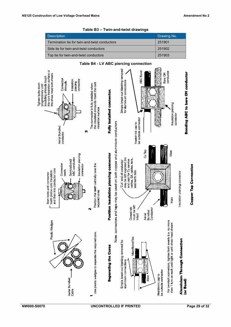
Table B3 – Twin-and-twist drawings Description Drawing No.
Termination tie for twin-and-twist conductors 251901
Side tie for twin-and-twist conductors 251902
Top tie for twin-and-twist conductors 251903
Table B4 - LV ABC piercing connection

NS125 Construction of Low Voltage Overhead Mains Amendment No 2
NW000-S0070 UNCONTROLLED IF PRINTED Page 30 of 32
Annexure C – LV ABC checklist Table C1 – LV ABC checklist
Insulated Fuse/Link Switch Disconnectors Yes No 1 Have the locations of the LV isolation points been identified from system/network
diagrams? 2 Has it been established if a minimum clearance of 4 metres above ground can be
achieved? 3 Has the supply end of the line been distinguished from the load end of the line? 4 Have the supply and load neutrals above the switching unit been joined using a
pre-insulated sleeve? 5 Has the supply end of the line been connected to the supply end of the link box? 6 Has the load end of the line been connected to the load end of the link box? 7 Has a drip loop been included in the conductor near the terminal? 8 Has the insulation been butted firmly against the terminal blocks? 9 Has the base of the link box been closed? 10 Has it been established that all necessary tools and equipment are available? Street Lighting 1 Has the system/network diagrams been checked to ensure that the street lighting
supply is maintained outside the LV ABC zone? 2 Have the existing lamps being fed formerly by the mains being replaced by ABC
been converted to PEC(s)? 3 Has the PEC been tested to ensure the lamp(s) is working? Clearances 1 Have all the minimum clearances of LV ABC from structures been met? 2 Have all the minimum clearances of LV ABC from ground been met? Lugs 1 Has the lug been pre-filled with jointing compound? 2 Has the lug been pre-insulated?
Accredited Service Provider: .................................................... Signature: ................................................................ Date:....................................................................... .

NS125 Construction of Low Voltage Overhead Mains Amendment No 2
NW000-S0070 UNCONTROLLED IF PRINTED Page 31 of 32
Annexure D – Sample compliance checklist

NS125 Construction of Low Voltage Overhead Mains Amendment No 2
NW000-S0070 UNCONTROLLED IF PRINTED Page 32 of 32