
ns Mounting Instructions Cel-Fi SOLO &ERH D Quick Start...
2
Cel-Fi ™ SOLO Quick Start Guide Box Contents: • Quick Start Guide • Cel-Fi SOLO Unit • Mounting Bracket • AC Adapter • Whip Antenna • Patch Antenna Specifications Cel-Fi ™ SOLO Quick Start Guide Box Contents: • Quick Start Guide • Cel-Fi SOLO Unit • Mounting Bracket • AC Adapter • Whip Antenna • Patch Antenna Mounting Instructions Determine Cel-Fi SOLO location. (Refer to Installation section). Determine mounting hole locations. 2 1 In each marked spot, use a 3/16” drill bit to drill guide holes for the anchors. Install anchors (Drywall). 3 Install mounting brackets. 4 Attach the Cel-Fi SOLO to the wall mounted bracket. REQUIRED HARDWARE Mounting Bracket Screws (4) Drywall Anchors (4) NOTE: This package comes equipped with screws and drywall anchors for mounting in standard drywall. Before you install the mounts, make sure there are no wires or other objects, or metal plates, behind the drywall that may interfere with the inserts, screws, mount, or mounted units. Additional Antenna Options Review the latest authorized antennas at: www.cel-fi.com/antennas Cel-Fi Indoor Omni Donor Antenna A52-V32-100 Cel-Fi Wideband Panel Antenna A11-V43-100 Cel-Fi LPDA Antenna A32-V32-100 Cel-Fi Wideband Directional Antenna A62-V44-100 Mounting Instructions Determine Cel-Fi SOLO location. (Refer to Installation section). Determine mounting hole locations. 2 1 In each marked spot, use a 3/16” drill bit to drill guide holes for the anchors. Install anchors (Drywall). 3 Install mounting brackets. 4 Attach the Cel-Fi SOLO to the wall mounted bracket. REQUIRED HARDWARE Mounting Bracket Screws (4) Drywall Anchors (4) NOTE: This package comes equipped with screws and drywall anchors for mounting in standard drywall. Before you install the mounts, make sure there are no wires or other objects, or metal plates, behind the drywall that may interfere with the inserts, screws, mount, or mounted units. Additional Antenna Options Review the latest authorized antennas at: www.cel-fi.com/antennas Cel-Fi Indoor Omni Donor Antenna A52-V32-100 Cel-Fi Wideband Panel Antenna A11-V43-100 Cel-Fi LPDA Antenna A32-V32-100 Cel-Fi Wideband Directional Antenna A62-V44-100 qsg-solo_eng_19-0212 Specifications &ERH Downlink (DL) Frequency(MHz) 2110 - 2170 Uplink (UL) Frequency 1920 - 1980 Per channel signal bandwidth (MHz) 20 Duplex separation (MHz) 190 Technology HSPA & LTE &ERH Downlink (DL) Frequency (MHz) 1805 - 1880 Uplink (UL) Frequency 1710 - 1785 Per channel signal bandwidth (MHz) 20 Duplex separation (MHz) 95 Technology HSPA & LTE &ERH Downlink (DL) Frequency (MHz) 2620 - 2690 Uplink (UL) Frequency 2500 - 2570 Per channel signal bandwidth (MHz) 20 Duplex separation (MHz) 120 Technology LTE &ERH Downlink (DL) Frequency (MHz) 925 - 960 Uplink (UL) Frequency 880 - 915 Per channel signal bandwidth (MHz) 15 Duplex separation (MHz) 45 Technology HSPA & LTE &ERH Downlink (DL) Frequency (MHz) 791 - 821 Uplink (UL) Frequency 832 - 862 Per channel signal bandwidth (MHz) 20 Duplex separation (MHz) -41 Technology LTE Airlink Supported Carriers - LTE 5, 10, 15, 20 MHz Supported Carriers - HSPA /W-CDMA 3.84 MHz Power Downlink Power - All Bands 20 dBm Uplink Power - Bands 1, 3, 7 24 dBm Uplink Power - Bands 8, 20 22 dBm Environmental Operating Temperature 0 - 40 º C Relative Humidity Non-condensing 0 - 95 RoHS (EU and China) Yes CE Yes IP Rating 20 Mechanical LxWxH (mm) 80 x 158 x 163 Weight Cooling Convection IP Rating 20 Surface Temp Max 44 º C Radio Performance Noise Figure 7dB Return Loss -8dB Antenna Ports Frequency 698MHz – 2700MHz Impedance 50 Ohms Connector SMA Female Port Isolation 110dB Specifications qsg-solo_eng_19-0212 Specifications &ERH Downlink (DL) Frequency(MHz) 2110 - 2170 Uplink (UL) Frequency 1920 - 1980 Per channel signal bandwidth (MHz) 20 Duplex separation (MHz) 190 Technology HSPA & LTE &ERH Downlink (DL) Frequency (MHz) 1805 - 1880 Uplink (UL) Frequency 1710 - 1785 Per channel signal bandwidth (MHz) 20 Duplex separation (MHz) 95 Technology HSPA & LTE &ERH Downlink (DL) Frequency (MHz) 2620 - 2690 Uplink (UL) Frequency 2500 - 2570 Per channel signal bandwidth (MHz) 20 Duplex separation (MHz) 120 Technology LTE &ERH Downlink (DL) Frequency (MHz) 925 - 960 Uplink (UL) Frequency 880 - 915 Per channel signal bandwidth (MHz) 15 Duplex separation (MHz) 45 Technology HSPA & LTE &ERH Downlink (DL) Frequency (MHz) 791 - 821 Uplink (UL) Frequency 832 - 862 Per channel signal bandwidth (MHz) 20 Duplex separation (MHz) -41 Technology LTE Airlink Supported Carriers - LTE 5, 10, 15, 20 MHz Supported Carriers - HSPA /W-CDMA 3.84 MHz Power Downlink Power - All Bands 20 dBm Uplink Power - Bands 1, 3, 7 24 dBm Uplink Power - Bands 8, 20 22 dBm Environmental Operating Temperature 0 - 40 º C Relative Humidity Non-condensing 0 - 95 RoHS (EU and China) Yes CE Yes IP Rating 20 Mechanical LxWxH (mm) 80 x 158 x 163 Weight Cooling Convection IP Rating 20 Surface Temp Max 44 º C Radio Performance Noise Figure 7dB Return Loss -8dB Antenna Ports Frequency 698MHz – 2700MHz Impedance 50 Ohms Connector SMA Female Port Isolation 110dB Specifications
Transcript of ns Mounting Instructions Cel-Fi SOLO &ERH D Quick Start...

Cel-Fi™ SOLOQuick Start Guide
Box Contents: • Quick Start Guide • Cel-Fi SOLO Unit• Mounting Bracket
• AC Adapter• Whip Antenna• Patch Antenna
Specifications
Cel-Fi™ SOLOQuick Start Guide
Box Contents: • Quick Start Guide • Cel-Fi SOLO Unit• Mounting Bracket
• AC Adapter• Whip Antenna• Patch Antenna
Mounting Instructions
Determine Cel-Fi SOLO location. (Refer to Installation section).
Determine mounting hole locations.
2
1In each marked spot, use a 3/16” drill bit to drill guide holes for the anchors. Install anchors (Drywall).
3 Install mounting brackets.
4 Attach the Cel-Fi SOLO to the wall mounted bracket.
REQUIRED HARDWAREMounting Bracket
Screws (4)Drywall Anchors (4)
NOTE: This package comes equipped with screws and drywall anchors for mounting in standard drywall. Before you install the mounts, make sure there are no wires or other objects, or metal plates, behind the drywall that may interfere with the inserts, screws, mount, or mounted units.
Additional Antenna OptionsReview the latest authorized antennas at: www.cel-fi.com/antennas
Cel-Fi Indoor OmniDonor AntennaA52-V32-100
Cel-Fi WidebandPanel AntennaA11-V43-100
Cel-Fi LPDA AntennaA32-V32-100
Cel-Fi WidebandDirectional AntennaA62-V44-100
qsg-solo_eng_19-0212
Specifications
Downlink (DL) Frequency(MHz) 2110 - 2170Uplink (UL) Frequency 1920 - 1980 Per channel signal bandwidth (MHz) 20Duplex separation (MHz) 190Technology HSPA & LTE
Downlink (DL) Frequency (MHz) 1805 - 1880Uplink (UL) Frequency 1710 - 1785Per channel signal bandwidth (MHz) 20Duplex separation (MHz) 95Technology HSPA & LTE
Downlink (DL) Frequency (MHz) 2620 - 2690Uplink (UL) Frequency 2500 - 2570Per channel signal bandwidth (MHz) 20Duplex separation (MHz) 120Technology LTE
Downlink (DL) Frequency (MHz) 925 - 960Uplink (UL) Frequency 880 - 915Per channel signal bandwidth (MHz) 15Duplex separation (MHz) 45Technology HSPA & LTE
Downlink (DL) Frequency (MHz) 791 - 821Uplink (UL) Frequency 832 - 862Per channel signal bandwidth (MHz) 20Duplex separation (MHz) -41Technology LTE
AirlinkSupported Carriers - LTE 5, 10, 15, 20 MHz
Supported Carriers - HSPA /W-CDMA
3.84 MHz
PowerDownlink Power - All Bands
20 dBm
Uplink Power - Bands 1, 3, 7
24 dBm
Uplink Power - Bands 8, 20
22 dBm
EnvironmentalOperating Temperature 0 - 40 º CRelative Humidity Non-condensing
0 - 95
RoHS (EU and China) Yes
CE YesIP Rating 20
MechanicalLxWxH (mm) 80 x 158 x 163WeightCooling ConvectionIP Rating 20Surface Temp Max 44 º C
Radio PerformanceNoise Figure 7dBReturn Loss -8dB
Antenna PortsFrequency 698MHz – 2700MHzImpedance 50 OhmsConnector SMA FemalePort Isolation 110dB
Specifications
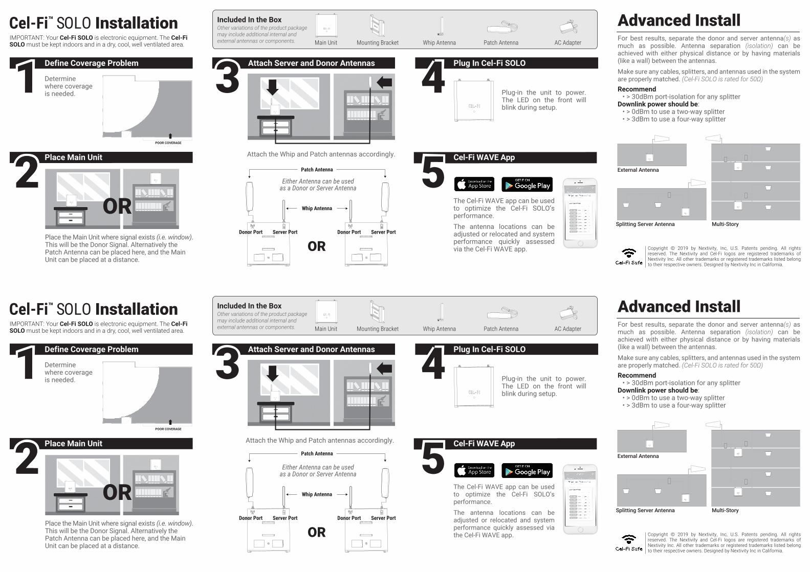
IMPORTANT: Your Cel-Fi SOLO is electronic equipment. The Cel-Fi SOLO must be kept indoors and in a dry, cool, well ventilated area.
Plug-in the unit to power. The LED on the front will blink during setup.
Attach the Whip and Patch antennas accordingly.
Determine where coverage is needed.
POOR COVERAGE
AC Adapter
Included In the BoxOther variations of the product package may include additional internal and external antennas or components. Whip Antenna Patch AntennaMounting BracketMain Unit
Attach Server and Donor AntennasDefine Coverage Problem Plug In Cel-Fi SOLO
Cel-Fi™ SOLO InstallationFor best results, separate the donor and server antenna(s) as much as possible. Antenna separation (isolation) can be achieved with either physical distance or by having materials (like a wall) between the antennas.
Make sure any cables, splitters, and antennas used in the system are properly matched. (Cel-Fi SOLO is rated for 50Ω)Recommend • > 30dBm port-isolation for any splitterDownlink power should be: • > 0dBm to use a two-way splitter • > 3dBm to use a four-way splitter
Advanced Install
Copyright © 2019 by Nextivity, Inc, U.S. Patents pending. All rights reserved. The Nextivity and Cel-Fi logos are registered trademarks of Nextivity Inc. All other trademarks or registered trademarks listed belong to their respective owners. Designed by Nextivity Inc in California.
11 33 44
The Cel-Fi WAVE app can be used to optimize the Cel-Fi SOLO’s performance. The antenna locations can be adjusted or relocated and system performance quickly assessed via the Cel-Fi WAVE app.
Cel-Fi WAVE App55Place the Main Unit where signal exists (i.e. window). This will be the Donor Signal. Alternatively the Patch Antenna can be placed here, and the Main Unit can be placed at a distance.
OR
Place Main Unit222
IMPORTANT: Your Cel-Fi SOLO is electronic equipment. The Cel-Fi SOLO must be kept indoors and in a dry, cool, well ventilated area.
Plug-in the unit to power. The LED on the front will blink during setup.
Attach the Whip and Patch antennas accordingly.
Determine where coverage is needed.
POOR COVERAGE
AC Adapter
Included In the BoxOther variations of the product package may include additional internal and external antennas or components. Whip Antenna Patch AntennaMounting BracketMain Unit
Attach Server and Donor AntennasDefine Coverage Problem Plug In Cel-Fi SOLO
Cel-Fi™ SOLO InstallationFor best results, separate the donor and server antenna(s) as much as possible. Antenna separation (isolation) can be achieved with either physical distance or by having materials (like a wall) between the antennas.
Make sure any cables, splitters, and antennas used in the system are properly matched. (Cel-Fi SOLO is rated for 50Ω)Recommend • > 30dBm port-isolation for any splitterDownlink power should be: • > 0dBm to use a two-way splitter • > 3dBm to use a four-way splitter
Advanced Install
External Antenna
Splitting Server Antenna Multi-Story
Copyright © 2019 by Nextivity, Inc, U.S. Patents pending. All rights reserved. The Nextivity and Cel-Fi logos are registered trademarks of Nextivity Inc. All other trademarks or registered trademarks listed belong to their respective owners. Designed by Nextivity Inc in California.
11 33 44
The Cel-Fi WAVE app can be used to optimize the Cel-Fi SOLO’s performance.
The antenna locations can be adjusted or relocated and system performance quickly assessed via the Cel-Fi WAVE app.
Cel-Fi WAVE App55OR
Place Main Unit222Place the Main Unit where signal exists (i.e. window). This will be the Donor Signal. Alternatively the Patch Antenna can be placed here, and the Main Unit can be placed at a distance.
External Antenna
Splitting Server Antenna Multi-Story
OR
Whip Antenna
Patch Antenna
Donor Port Server Port
Either Antenna can be usedas a Donor or Server Antenna
Donor Port Server Port
OR
Whip Antenna
Patch Antenna
Donor Port Server Port
Either Antenna can be usedas a Donor or Server Antenna
Donor Port Server Port


![documents must be submitted before May 1, 2014. The ... · erh %hnywxqirxw ;svowliix sr teki y -j ]sy evi wmrkpi erh leziqsvi xler sri nsf sv evi qevvmih erh ]sy erh ]syv wtsywi fsxl](https://static.fdocuments.us/doc/165x107/5f767a7a5d7f841ee44870af/documents-must-be-submitted-before-may-1-2014-the-erh-hnywxqirxw-svowliix.jpg)


