NREL/CP-540-44833 Oil Dilution on Light-Duty Diesel Engine Operation · · 2013-09-26Oil Dilution...
11
Conference Paper NREL/CP-540-44833 August 2009 Impacts of Biodiesel Fuel Blends Oil Dilution on Light-Duty Diesel Engine Operation M.J. Thornton, T.L. Alleman, J. Luecke, and R.L. McCormick Presented at the 2009 SAE International Powertrains, Fuels, and Lubricants Meeting Florence, Italy June 15−17, 2009
Transcript of NREL/CP-540-44833 Oil Dilution on Light-Duty Diesel Engine Operation · · 2013-09-26Oil Dilution...

Conference Paper NREL/CP-540-44833 August 2009
Impacts of Biodiesel Fuel Blends Oil Dilution on Light-Duty Diesel Engine Operation M.J. Thornton, T.L. Alleman, J. Luecke, and R.L. McCormick Presented at the 2009 SAE International Powertrains, Fuels, and Lubricants Meeting Florence, Italy June 15−17, 2009

NOTICE
The submitted manuscript has been offered by an employee of the Alliance for Sustainable Energy, LLC (ASE), a contractor of the US Government under Contract No. DE-AC36-08-GO28308. Accordingly, the US Government and ASE retain a nonexclusive royalty-free license to publish or reproduce the published form of this contribution, or allow others to do so, for US Government purposes.
This report was prepared as an account of work sponsored by an agency of the United States government. Neither the United States government nor any agency thereof, nor any of their employees, makes any warranty, express or implied, or assumes any legal liability or responsibility for the accuracy, completeness, or usefulness of any information, apparatus, product, or process disclosed, or represents that its use would not infringe privately owned rights. Reference herein to any specific commercial product, process, or service by trade name, trademark, manufacturer, or otherwise does not necessarily constitute or imply its endorsement, recommendation, or favoring by the United States government or any agency thereof. The views and opinions of authors expressed herein do not necessarily state or reflect those of the United States government or any agency thereof.
Available electronically at http://www.osti.gov/bridge
Available for a processing fee to U.S. Department of Energy and its contractors, in paper, from:
U.S. Department of Energy Office of Scientific and Technical Information P.O. Box 62 Oak Ridge, TN 37831-0062 phone: 865.576.8401 fax: 865.576.5728 email: mailto:[email protected]
Available for sale to the public, in paper, from: U.S. Department of Commerce National Technical Information Service 5285 Port Royal Road Springfield, VA 22161 phone: 800.553.6847 fax: 703.605.6900 email: [email protected] online ordering: http://www.ntis.gov/ordering.htm
Printed on paper containing at least 50% wastepaper, including 20% postconsumer waste

Impacts of Biodiesel Fuel Blends Oil Dilution on Light-Duty Diesel Engine Operation
Matthew J. Thornton, Teresa L. Alleman, Jon Luecke, and Robert L. McCormick National Renewable Energy Laboratory
ABSTRACT
Increasing interest in biofuels—specifically, biodiesel as a pathway to energy diversity and security—has necessitated the need for research on the performance and utilization of these fuels and fuel blends in current and future vehicle fleets. One critical research area is related to achieving a full understanding of the impact of biodiesel fuel blends on advanced emission control systems. In addition, the use of biodiesel fuel blends can degrade diesel engine oil performance and impact oil drain interval requirements.
There is limited information related to the impact of biodiesel fuel blends on oil dilution. This paper assesses the oil dilution impacts on an engine operating in conjunction with a diesel particle filter (DPF), oxides of nitrogen (NOx) storage, a selective catalytic reduction (SCR) emission control system, and a 20% biodiesel (soy-derived) fuel blend. The main focus was on the biodiesel oil dilution levels observed during an accelerated aging protocol and an assessment of the potential impacts on the engine and emissions control systems. For the NOx storage system (which requires a late in-cylinder fuel injection for regeneration), biodiesel oil dilution levels ranged from 5%10%. For the SCR system (which used a urea solution as a reductant and late in-cylinder fuel injection for diesel particle filter regeneration), biodiesel oil dilution ranged from <4%8%. These observations were made over typical oil drain intervals. Despite these observed biodiesel oil dilution levels, there were no observed impacts on the performance of the engine or the emission control systems.
INTRODUCTION
Biodiesel fuel blends are one option currently being researched as a pathway to energy diversity and reduced petroleum dependence in the transportation sector. One of the key factors related to the success of biodiesel fuel blends is their compatibility with vehicle components such as fuel systems, combustion parts, and advanced emission control systems. However, one way that biodiesel fuel blends can create potential problems affecting vehicle operation is through accelerated dilution of the oil by the fuel. This is particularly important for vehicles utilizing advanced emissions control systems that require late in-cylinder fuel injection. Excessive oil dilution has the potential to lead to several problems, such as reduced oil performance and durability (e.g., decreased viscosity or the development of oil sludge) and catalyst poisoning. At a minimum, oil dilution could impact the interval requirements for oil changes, the effectiveness of additive packages, and sump capacity. Acceptable oil dilution limits for original equipment manufacturers (OEMs) range up to 50% [1], but most OEMs want limits to be much lower.
Biodiesel is a renewable fuel derived from vegetable oil, animal fat, or waste cooking oil, and it consists of the methyl esters of fatty acids. It is typically used as a diesel blending component at levels up to 20% by volume. Life-cycle analysis indicates that the use of biodiesel can help displace imported petroleum in the United States, and resource assessments have indicated that biodiesel has the potential to displace 5% or more of petroleum diesel over the next decade [2, 3]. However, because biodiesel has a relatively higher
A similar paper is published as SAE 2009-01-1790.
1

distillation temperature and boiling point, when it is present in post-injected fuel it tends to dilute the oil on a level disproportionate to its blend ratio in the fuel [4, 5, 6]. This leads to a concern about oil dilution.
Current research at the National Renewable Energy Laboratory (NREL) on the impacts of biodiesel on emission control systems has provided an opportunity to also evaluate the impact of biodiesel fuel blends on oil dilution and its associated impacts on the performance of the engine and emission control system. As a corollary to a larger research project at NREL on biodiesel impacts on selective catalytic reduction (SCR) with urea and oxides of nitrogen (NOx) adsorber catalyst (NAC) systems [7, 8], researchers assessed biodiesel’s impacts on oil dilution. The purpose of this paper is to document the oil dilution observed in this research project and assess any potential engine or emission control system impacts.
HARDWARE DESCRIPTION
The following sections provide an overview of the hardware components used during the project. The test vehicle and test engines were procured by the U.S. Department of Energy in direct support of this project. All the catalyst hardware, as well as the urea dosing system, was supplied by the Manufacturers of Emissions Controls Association (MECA).
ENGINE HARDWARE The engine used for this project in the test cell as well as in the vehicle was a 4-cylinder 2.15 L high-speed direct injection (HSDI) diesel engine. The original engine calibration complied with Euro 4 emission standards. The engine utilized a conventional high-pressure exhaust gas recirculation (EGR) loop, a second-generation common-rail fuel injection system (1600 bar maximum injection pressure, solenoid injectors) with all actuators electrically controlled. Table 1 lists the main parameters of the test engine.
Table 1: Engine specifications
Engine Power 113 kW at 4000 rpm
Peak Torque 360 Nm at 2000 rpm
Maximum Engine Speed 4700 rpm
Maximum BMEP 21 bar
Cylinder Arrangement 4-Cylinder Inline
Firing Order 1 – 3 – 4 – 2
Valve Train 4 Valve DOHC
Bore to Stroke Ratio 1.0034
Displacement 2.15 L
Compression Ratio 18:1
Fuel Injection System 2nd Generation Common Rail
The test vehicle was a conventional four-door sedan vehicle in the 1,700 kg class. It met the Euro 4 emission standards and was equipped with a catalyzed diesel
particle filter (DPF) as a standard feature. Table 2 lists the relevant vehicle features.
Table 2: Vehicle specifications
Criterion Unit Value Vehicle Mass kg 1,700 Air Drag Coefficient - 0.29 Frontal Surface Area m2 2.20 Transmission Gear Ratio 1st 4.99
2nd 2.82 3rd 1.78 4th 1.25 5th 1.00 6th 0.82
Axle 2.65 Tires Rear 205 / 55 R 16 91 H
Front 205 / 55 R 16 91 H
CATALYST SPECIFICATIONS Two emission control systems (ECS) were developed and tested separately as part of this project. These included an NAC/DPF system and a SCR/DPF system. The NAC was located in a close-coupled position, directly after the turbine exit with minimal distance to the catalyst to allow for rapid heat-up of this NOx treatment unit; the DPF was located under the floor. The SCR catalyst was also located under the floor and was followed by the DPF in the same can, with a close-coupled diesel oxidation catalyst (DOC). All the piping between the DOC exit and the SCR inlet was made of dual-wall exhaust pipe to increase heat preservation during operation. MECA provided all the ECS components. Table 3 lists all the catalyst specifications for this project.
Table 3: Catalyst specifications for each component
Component System Volume
[L]
Cell Density [cpsi]
PGM loading [g/ft3]
NAC System
DOC 0.8 400 150
DPF 3.3 300 60
NAC 4.1 400 120
SCR System
DOC 1.23 400 150
DPF 4.1 300 60
SCR Fe-ZSM-5 4.43 300 N/A
FUEL AND OIL SPECIFICATIONS An ultra-low-sulfur diesel fuel (ULSD), also referred to as the base fuel, was used to blend the 20% by volume soy-derived methyl ester. Table 4 lists the fuel specifications for each tested fuel type. The effects on the fuel specifications as a result of the increased amount of methyl ester become particularly noticeable in the heating value, the cetane number, and the oxygen content. The base lube oil used for this study was CJ-4 oil.
2

Table 4: Fuel specifications
Specification Unit ASTM
Method ULSD B20
Net Heating Value
MJ/kg D240 42.53 41.52
Cetane Number
- D6890 41.4 45.6
Density at 15°C
kg/m3 D4052 847.5 852.9
Viscosity at 40°C
mm2/sec D445 2.429 2.685
Carbon wt% D5291 87.04 85.01
Oxygen wt% By
difference 0.00 2.29
Hydrogen wt% D5291 12.96 12.70
LATE IN-CYLINDER FUEL INJECTION EVENTS
Oil dilution in diesel engines will occur over time with normal operation, leading to oil degradation and the need for oil replacement. With increased use of advanced emission control devices, oil dilution impacts can also increase as a result of late in-cylinder fuel injection events used in conjunction with some of these devices [4, 6]. The late injection events are used as a regeneration strategy for DPFs as well as NACs. These late injection events increase the opportunity for unburned fuel to reach the cylinder walls and in turn enter the lubricating oil. With conventional diesel fuel it can boil out of the lube oil, minimizing long-term dilution effects. However, this effect is accentuated with biodiesel because of its high boiling point relative to petroleum diesel, which can lead to a disproportionate amount of fuel being retained in the lube oil. Three main late injection events are associated with DPF and NAC operation that can accentuate the oil dilution problem. These include lean-rich modulation used for NAC regeneration, desulfurization used to liberate the NAC from accumulated fuel-borne sulfur, and DPF regeneration used to burn off accumulated soot from the DPF substrate.
LEAN-RICH MODULATION NAC regeneration is a key component of meeting NOx emission standards with an NAC system. A short pulse of rich exhaust gas desorbs the NOx emissions and subsequently reduces them, following the well-known chemistry of the three-way catalyst, described in more detail in the next section. These events occur quite frequently (e.g., every one to two minutes). The goal is to obtain the required rich exhaust conditions with a diesel engine that typically operates under lean conditions. Lean-rich modulation through late in-cylinder fuel injection is used to achieve
the rich exhaust conditions required by the NAC, but this also has the potential to lead to increased oil dilution.
Desulfurization The basic principle of NAC is the adsorption of NO2 during the lean operating phases of the engine. The NO2 is adsorbed by alkaline earth oxides forming nitrates such as Ba (NO3)2. The nitrates become unstable and release the NO and NO2 at high temperature (thermal release of NOx) or during rich exhaust conditions. The rich exhaust conditions allow the three-way-catalyst mechanism to be used to reduce the released NOx into N2 and CO2. In addition to their desired functions, NACs exhibit the undesired function of adsorbing SO3
-2 and forming BaSO4, which is a considerably more stable compound requiring high temperatures and stoichiometric operating conditions to be released. This release or desulfurization has to occur relatively frequently to avoid catalyst deactivation. The frequency of this event depends on the fuel sulfur level as well as the contribution of the engine lubricating oil. The rich operation required to create these high-temperature desulfurization conditions also requires late in-cylinder fuel injection, and that in turn creates an opportunity for increased oil dilution.
DPF REGENERATION DPF regeneration is occasionally required in order to oxidize the accumulated soot that collects on the DPF during normal engine operation. As with NAC regeneration and NAC desulfurization, late in-cylinder fuel injection is used to create the high temperatures over the DPF required to burn or oxidize the accumulated soot. This provides another opportunity for increased oil dilution, and it would be the case for both NAC systems and SCR systems.
AGING TEST CYCLE
Both systems were aged to an equivalent of 120,000 miles, or full useful life, and the oil was sampled at regular intervals during this aging. In order to simulate the appropriate aging conditions, the engine and ECS were exposed to an equivalent useful lifetime of fuel in the engine dynamometer test cell. To keep the aging time at a reasonable level, the aging duration for each ECS was set to be accomplished in approximately 700 hours. The following assumptions were used regarding fuel consumption for the system:
Highway Fuel Economy Test (HFET) fuel economy of 55 mpg
Urban Dynamometer Driving Schedule (UDDS) cycle fuel economy of 33 mpg
Split of ¾ HFET and ¼ UDDS
These assumptions resulted in an average fuel economy of 49.5 mpg. At 120,000 miles, this equates to 2,424 gallons or 7,708 kg of fuel. Given the 700 hours of aging time, an average fuel consumption of approximately 11
3
kg/hr was established. Three operating phases were established to reflect real in-use operating modes:
1. NAC operation using the systems efficiency control algorithms to determine the frequency of regeneration events
2. DPF regeneration (300 for full useful life, 20 minutes each)
3. Desulfurization (25 for full useful life for the NAC system only, 20 minutes each)
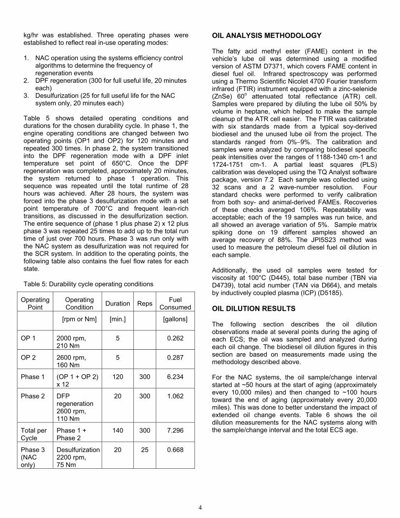
Table 5 shows detailed operating conditions and durations for the chosen durability cycle. In phase 1, the engine operating conditions are changed between two operating points (OP1 and OP2) for 120 minutes and repeated 300 times. In phase 2, the system transitioned into the DPF regeneration mode with a DPF inlet temperature set point of 650°C. Once the DPF regeneration was completed, approximately 20 minutes, the system returned to phase 1 operation. This sequence was repeated until the total runtime of 28 hours was achieved. After 28 hours, the system was forced into the phase 3 desulfurization mode with a set point temperature of 700°C and frequent lean-rich transitions, as discussed in the desulfurization section. The entire sequence of (phase 1 plus phase 2) x 12 plus phase 3 was repeated 25 times to add up to the total run time of just over 700 hours. Phase 3 was run only with the NAC system as desulfurization was not required for the SCR system. In addition to the operating points, the following table also contains the fuel flow rates for each state.
Table 5: Durability cycle operating conditions
Operating Point
Operating Condition
Duration Reps Fuel
Consumed
[rpm or Nm] [min.] [gallons]
OP 1 2000 rpm, 210 Nm
5 0.262
OP 2 2600 rpm, 160 Nm
5 0.287
Phase 1 (OP 1 + OP 2) x 12
120 300 6.234
Phase 2 DFP regeneration 2600 rpm, 110 Nm
20 300 1.062
Total per Cycle
Phase 1 + Phase 2
140 300 7.296
Phase 3 (NAC only)
Desulfurization 2200 rpm, 75 Nm
20 25 0.668
OIL ANALYSIS METHODOLOGY
The fatty acid methyl ester (FAME) content in the vehicle’s lube oil was determined using a modified version of ASTM D7371, which covers FAME content in diesel fuel oil. Infrared spectroscopy was performed using a Thermo Scientific Nicolet 4700 Fourier transform infrared (FTIR) instrument equipped with a zinc-selenide (ZnSe) 60o attenuated total reflectance (ATR) cell. Samples were prepared by diluting the lube oil 50% by volume in heptane, which helped to make the sample cleanup of the ATR cell easier. The FTIR was calibrated with six standards made from a typical soy-derived biodiesel and the unused lube oil from the project. The standards ranged from 0%9%. The calibration and samples were analyzed by comparing biodiesel specific peak intensities over the ranges of 1188-1340 cm-1 and 1724-1751 cm-1. A partial least squares (PLS) calibration was developed using the TQ Analyst software package, version 7.2 Each sample was collected using 32 scans and a 2 wave-number resolution. Four standard checks were performed to verify calibration from both soy- and animal-derived FAMEs. Recoveries of these checks averaged 106%. Repeatability was acceptable; each of the 19 samples was run twice, and all showed an average variation of 5%. Sample matrix spiking done on 19 different samples showed an average recovery of 88%. The JPI5S23 method was used to measure the petroleum diesel fuel oil dilution in each sample.
Additionally, the used oil samples were tested for viscosity at 100°C (D445), total base number (TBN via D4739), total acid number (TAN via D664), and metals by inductively coupled plasma (ICP) (D5185).
OIL DILUTION RESULTS
The following section describes the oil dilution observations made at several points during the aging of each ECS; the oil was sampled and analyzed during each oil change. The biodiesel oil dilution figures in this section are based on measurements made using the methodology described above.
For the NAC systems, the oil sample/change interval started at ~50 hours at the start of aging (approximately every 10,000 miles) and then changed to ~100 hours toward the end of aging (approximately every 20,000 miles). This was done to better understand the impact of extended oil change events. Table 6 shows the oil dilution measurements for the NAC systems along with the sample/change interval and the total ECS age.
4

Table 6: Oil dilution measurements for the NAC system Viscosity decreased with increasing oil age and
Sample #
Oil Age (hours)
System Age
(hours)
Biodiesel Oil
Dilution (%)
Diesel Oil
Dilution (%)
1 48 48 4.7 2.9
2 92 140 6.6 3.4
3 65 205 5.2 4.2
4 90 295 5.7 _
5 67 362 5.3 2.0
6 65 427 6.8 3.0
7 65 492 5.9 2.7
8 100 592 8.3 3.5
9 158 750 10.1 4.1
increasing diesel fuel dilution, but it never went below 11 cSt. TBN decreased sharply with oil age, getting as low as 2.44 mg KOH/g for 150-hour oil, while TAN increased slightly to 2.26 mg/KOH/g. Iron in the oil increased with age, reaching a level of 55 ppm at 150 hours. Lead was below detection except for samples exceeding 100 hours in age, where it was 3 ppm.
For the SCR systems, the oil sample/change interval started at ~50 hours and remained at that interval for the entire aging process (approximately every 10,000 miles). Table 7 shows the oil dilution measurements for the SCR systems along with the oil sample/change interval and the total ECS age.
Table 7 shows that the biodiesel oil dilution levels for the SCR systems range from less than 4% to 8%. As shown in Figure 2, the biodiesel oil dilution levels for the SCR system, relative to oil age, are similar to those associated with the NAC system. This result was observed despite the fact that the SCR system was exposed to far fewer late in-cylinder fuel injection events. The SCR system was exposed to only 16 to 27 late in-cylinder fuel injection events, depending on the oil change sample/interval. These events were associated with the DPF regeneration. It appears that oil age, and not late in-cylinder fuel injection events, is the driving factor in determining biodiesel oil dilution levels.
Used oil age never exceeded 80 hours for the SCR As Table 6 shows, biodiesel oil dilution levels for the NAC system ranged from less than 5% to 10%; the highest measurements were associated with longer oil change intervals that occurred at the end of the aging. Each oil sample was exposed to numerous late in-cylinder fuel injection events for NAC and DPF regeneration and NAC desulfurization. NAC regeneration events were the most frequent, ranging from 605 to 2,010 events per oil change. The DPF regeneration events ranged from 21 to 65 per oil change event, and the desulfurization events occurred only a few times per oil change. Figure 1 shows the number of late in-cylinder fuel injection events by category. A comparison of this figure with Table 6 shows that biodiesel oil dilution levels track with the frequency of
system. Viscosity was approximately constant for the used oils, at about 13.9 cSt. TBN decreased slightly with oil age, reaching a low value of 4.54 mg/KOH/g at 75 hours, while TAN was essentially constant at about 2 mg/KOH/g. Iron in the oil increased with oil age but never exceeded 12 ppm; other wear metals were below detection limits.
The main observations are a significant reduction in TBN for the lubricant in both systems and a higher level of iron in used lubricant for the NAC system. The researchers anticipate that biodiesel in the lubricant will oxidize to produce acids, causing a reduction in TBN. Biodiesel content in the oil increases with oil age for both the NAC system and the SCR system. Figure 3 shows late in-cylinder injection events, but also with oil age. that the rate of TBN decrease with oil age is identical for
0
500
1000
1500
2000
2500
3000
0
10
20
30
40
50
60
70
NA
C
DP
F a
nd
De
sulf # DPF regeneration
# Desulfurization
# NAC regenartion
the SCR and NAC systems, indicating that the main factor affecting TBN loss is simply lubricant age, not biodiesel content. TAN never exceeds TBN, indicating that even up to 150 hours the lubricant service interval had not been exceeded.
Oil sample intervals (hours)
Figure 1: Late in-cylinder fuel injection events by category as a function of ECS age
5

Table 7: Oil dilution measurements for SCR system EMISSIONS IMPACTS
Sample #
Oil Age (hours)
System Age
(hours)
Biodiesel Oil
Dilution (%)
Diesel Oil
Dilution (%)
1 65 65 8.0 4.6
2 76 141 7.6 4.0
3 54 195 6.5 3.1
4 65 260 7.0 3.3
5 59 319 4.1 1.6
6 63 382 4.7 1.8
7 58 440 4.1 1.6
8 64 504 3.7 1.0
9 64 568 3.6 1.0
10 45 613 3.7 1.4
At two points, during and after the completion of the durability testing with each ECS, the components were installed in the project vehicle and underwent emissions testing. All of the following vehicle tests were conducted at EPA’s National Vehicle and Fuel Emissions Laboratory. The vehicle was tested using a 48-inchdiameter, single-roll, electric chassis dynamometer. The tests showed that Tier 2 Bin 5 emission levels could be met with the NAC ECS. However, the performance of the SCR system degraded to a point at which Tier 2 Bin 5 limits could not be met. Figure 4 and Table 8 show the system performance in the course of the aging process for both ECS.
12
Tier2 Bin5 50k Tier2 Bin5 120k
NAC DPF : 0hr Composite FTP 75 NAC DPF : Full Useful Life Composite FTP 75 SCR DPF : 0hr Composite FTP 75 SCR DPF : Full Useful Life Composite FTP 75 P
M [
mg
/mil
e]
10
8
6
4
2
0 0.00 0.05 0.10 0.15 0.20 0.25
NOx [g/mile]
Figure 2: Lubricant biodiesel content as a function of lubricant age
Figure 3: TBN and TAN as a function of lubricant age for both systems
0.16
0.14
0.12
0.10
0.08
0.06
0.04
0.02
0.00
NM
HC
[g
/mil
e]
0.0 0.5 1.0 1.5 2.0 2.5 3.0 3.5 4.0 4.5 CO [g/mile]
Figure 4: Emission results with new and useful life aged components
Although the desired NOx and NMHC emission levels for the SCR system were not met, the researchers believe that this was the result of degradation of the SCR catalyst from thermal shock due to hydrocarbon (HC) adsorption and loss of cold start performance, and not a result of fuel or fuel oil dilution impacts. The Tier 2 Bin 5 emission levels could be met with the SCR system for PM and CO.
Table 8: Emission results with new and useful life aged components, FTP 75 (g/mi)
System NOx PM CO NMHC
NAC 0 hr 0.031 0.0012 0.163 0.149
NAC 700 hr 0.061 0.0016 0.690 0.072
SCR 0 hr 0.044 0.0005 0.247 0.019
SCR 700 hr 0.230 0.0004 1.212 0.145
6

ENGINE COMPONENT IMPACTS
After the completion of the durability tests for the NAC and the SCR system, the engine had undergone an accelerated aging schedule representative of twice its useful life, or approximately 240,000 miles. At the conclusion of the project, the engine was disassembled and each component was carefully analyzed. All moving parts such as bearings, pistons, and piston rings were inspected and measured. None of the components of the engine, including the injectors, showed signs of excessive wear or other signs of deterioration as a result of the extended biodiesel operation. The flow characteristics of the injectors remained comparable to levels noted before the start of the durability study. Figure 5 shows several engine components after the disassembly.
The cylinder bore in the upper left corner of Figure 5 shows the honing pattern, which indicates that there was no loss in oil control for this engine. The main bearing shown below the cylinder bore showed no sign of deterioration or wear. This component is prone to wear caused by oil dilution and the resulting loss in lubricity of the engine oil. On the main journal as well as one cam, shown on the right side of the figure, no visible signs of wear were detected.
CONCLUSION
The completed project included an evaluation of two emission control systems tested in conjunction with a biodiesel blend fuel. The focus of this paper was on the biodiesel oil dilution levels observed for both systems utilizing a 20% biodiesel blend. For the NAC system (which requires a late in-cylinder fuel injection for regeneration), the biodiesel oil dilution level ranged from 5%10% for oil samples ranging in age from ~50 to ~150 hours. For the SCR system (which used a urea solution as a reductant and required only late in-cylinder fuel injection for DPF regeneration), biodiesel oil dilution ranged from <4%8% for oil samples ranging in age from ~50 to ~75 hours. The rate of biodiesel accumulation in the oil as a function of oil age was similar for both ECS, despite the fact that the SCR system saw fewer late in-cylinder fuel injection events. There were no obvious biodiesel specific effects on used lube oil properties, and most changes appeared to be consistent with normal lube oil aging. Based on a comparison of TBN and TAN, oil service life was never exceeded in these tests. Despite these biodiesel oil dilution levels, no impacts were observed on the performance of the engine or the emission control systems.
Figure 5: Selected engine components
7

Durability tests with both emission control systems [8] demonstrated that the NAC system provides sustainable conversion efficiencies over its useful life. However, the SCR system did experience performance degradation, which was attributed to the deactivation of the iron-zeolite through thermal shock.
Finally, no biodiesel-related wear and engine mechanics deterioration were found after the hardware was exposed to an accelerated aging protocol of twice the engine’s useful life.
ACKNOWLEDGMENTS
The authors express their gratitude to all the team members who supported the project and contributed to all the technical discussions.
This work was supported jointly by the U.S. Department of Energy (DOE) Office of Vehicle Technologies and by the National Biodiesel Board (NBB). Special thanks to Kevin Stork and Dennis Smith of DOE and to Steve Howell at the NBB.
The authors also acknowledge Joe Kubsh and Rasto Brezny of MECA and team members for the in-kind contributions of all exhaust ECS hardware, Charles Schenk of the U.S. EPA for providing access to the chassis dynamometer for the vehicle tests, and Harsha Nanjundaswamy and Marek Tatur of FEV Incorporated for managing the testing program.
REFERENCES
1. R. Kotrba, “Understanding the Post-Injection Problem,” Biodiesel Magazine, Vol. 5, No. 5, May 2008.
2. John Sheehan, Vince Camobreco, James Duffield, Michael Graboski, and Housein Shapouri, An Overview of Biodiesel and Petroleum Diesel Life Cycles, NREL/TP-580-24772, May 1998.
3. K. S. Tyson, J. Bozell, R. Wallace, E. Petersen, and L. Moens, Biomass Oil Analysis: Research Needs and Recommendations. NREL/TP-510-34796. Golden, CO: National Renewable Energy Laboratory, June 2004.
4. Andrea Morgan, Howard Fang, and Bhandary Kirtan, “Biodiesel on Fuel Dilution of Engine Oil,” SAE 2007-01-4036.
5. Cathy C. Devlin, Charles Passut, Tze-Chi Jao, and Bob Campbell, “Biodiesel Fuel Effect on Diesel Engine Lubrication,” SAE 2008-01-2375.
6. Howard Fang, Shawn Whitacre, Elaine Yamaguchi, and Maarten Boons, “Biodiesel Impact on Wear Protection of Engine Oils,” SAE 2007-01-4141.
7. Marek Tatur, Harsha Nanjundaswamy, Dean Tomazic, and Matthew Thornton, “Biodiesel Effects on U.S. Light-Duty Tier 2 Engine and Emission Control Systems,” SAE 2008-01-0080.
8. Marek Tatur, Harsha Nanjundaswamy, Dean Tomazic, and Matthew Thornton, “Biodiesel Effects on U.S. Light-Duty Tier 2 Engine and Emission Control Systems-Part 2,” SAE 2009-01-0281.
CONTACT
Matthew Thornton, Senior Engineer, National Renewable Energy Laboratory (NREL), [email protected].
DEFINITIONS, ACRONYMS, ABBREVIATIONS
ATR: attenuated total reflectance Ba: Barium BMEP: brake mean effective pressure B20: biodiesel with 20% renewable fuels content CO: carbon monoxide CO2: carbon dioxide cpsi: cells per square inch DOC: diesel oxidation catalyst DOE: U.S. Department of Energy DOHC: double overhead camshaft DPF: diesel particle filter ECS: emission control system EGR: exhaust gas recirculation EPA: Environmental Protection Agency EURO: European FAME: fatty acid methyl ester FTIR: Fourier transform infrared (spectroscopy) FTP: Federal Test Procedure HC: hydrocarbon HFET: Highway Fuel Economy Test HSDI: high-speed direct injection MECA: Manufactures of Emission Controls Association NAC: NOxadsorber catalyst NMHC: non-methane hydrocarbons NO: nitric oxide NO2: nitrogen dioxide NOx: oxides of nitrogen NREL: National Renewable Energy Laboratory O2 oxygen OEM: original equipment manufacturer PM: particulate matter PGM: platinum group metal RPM: revolutions per minute (engine speed) SCR: selective catalytic reduction TAN: total acid number TBN: total base number THC: total hydrocarbon UDDS: Urban Dynamometer Driving Schedule ULSD: ultra-low-sulfur diesel (here, the base fuel)
8

F1147-E(10/2008)
REPORT DOCUMENTATION PAGE Form Approved OMB No. 0704-0188
The public reporting burden for this collection of information is estimated to average 1 hour per response, including the time for reviewing instructions, searching existing data sources, gathering and maintaining the data needed, and completing and reviewing the collection of information. Send comments regarding this burden estimate or any other aspect of this collection of information, including suggestions for reducing the burden, to Department of Defense, Executive Services and Communications Directorate (0704-0188). Respondents should be aware that notwithstanding any other provision of law, no person shall be subject to any penalty for failing to comply with a collection of information if it does not display a currently valid OMB control number. PLEASE DO NOT RETURN YOUR FORM TO THE ABOVE ORGANIZATION. 1. REPORT DATE (DD-MM-YYYY)
August 2009 2. REPORT TYPE
Conference Paper 3. DATES COVERED (From - To)
4. TITLE AND SUBTITLE
Impacts of Biodiesel Fuel Blends Oil Dilution on Light-Duty Diesel Engine Operation
5a. CONTRACT NUMBER DE-AC36-08-GO28308
5b. GRANT NUMBER
5c. PROGRAM ELEMENT NUMBER
6. AUTHOR(S) M.J. Thornton, T.L. Alleman, J. Luecke, and R.L. McCormick
5d. PROJECT NUMBER NREL/CP-540-44833
5e. TASK NUMBER FC089400
5f. WORK UNIT NUMBER
7. PERFORMING ORGANIZATION NAME(S) AND ADDRESS(ES) National Renewable Energy Laboratory 1617 Cole Blvd. Golden, CO 80401-3393
8. PERFORMING ORGANIZATION REPORT NUMBER NREL/CP-540-44833
9. SPONSORING/MONITORING AGENCY NAME(S) AND ADDRESS(ES)
10. SPONSOR/MONITOR'S ACRONYM(S) NREL
11. SPONSORING/MONITORING AGENCY REPORT NUMBER
12. DISTRIBUTION AVAILABILITY STATEMENT National Technical Information Service U.S. Department of Commerce 5285 Port Royal Road Springfield, VA 22161
13. SUPPLEMENTARY NOTES
14. ABSTRACT (Maximum 200 Words) This paper assesses the oil dilution impacts on an engine operating in conjunction with a diesel particle filter (DPF), oxides of nitrogen (NOx) storage, a selective catalytic reduction (SCR) emission control system, and a 20% soy-based biodiesel fuel blend. The focus was on biodiesel oil dilution levels observed during an accelerated aging protocol and an assessment of the potential impacts on the engine and emissions control systems. For the NOx storage system, which requires a late in-cylinder fuel injection for regeneration, biodiesel oil dilution levels ranged from 5% to 10%. For the SCR system, which used a urea solution as a reductant and late in-cylinder fuel injection for DPF regeneration, biodiesel oil dilution ranged from <4% to 8%, as observed over typical oil drain intervals. Despite observed biodiesel oil dilution levels, no impacts were observed on engine performance or emission control systems.
15. SUBJECT TERMS biodiesel fuel; diesel engine; fuel oil dilution; diesel emissions; diesel particle filter; selective catalytic reduction; emission control system
16. SECURITY CLASSIFICATION OF: 17. LIMITATION OF ABSTRACT
UL
18. NUMBER OF PAGES
19a. NAME OF RESPONSIBLE PERSON a. REPORT
Unclassified b. ABSTRACT Unclassified
c. THIS PAGE Unclassified 19b. TELEPHONE NUMBER (Include area code)
Standard Form 298 (Rev. 8/98) Prescribed by ANSI Std. Z39.18