NPS/003/039 Technical Specification for Substation DC ...Electrical and Environmental Standards ......
18
Document reference NPS/003/039 Document Type Code of Practice Version:- 1.0 Date of Issue:- April 2016 Page 1 of 18 CAUTION! - This document may be out of date if printed NPS/003/039 – Technical Specification for Substation DC Disconnection Schemes 1. Purpose The purpose of this document is to detail the technical requirements of substation tripping battery DC Disconnection Schemes to be installed at specified sites in order to meet the requirements stated in ENA Engineering Recommendation G91 Substation Black Start Resilience. The baseline requirement set out in ENA ER G91 is for primary and supply point substations to be designed so that they are resilient for a minimum period of 72 hours from the inception of a Black Start event. During this time substation protection, control and SCADA functions shall be available such that the site can be safely energised and subsequently used to restore customer supplies. At specified sites, 72 hours resilience of the closing and tripping batteries shall be achieved by disconnecting the batteries by an appropriately rated device and re-energised prior to the restoration of supplies. SCADA batteries shall be reinforced to provide 72 hours continuous supply to control functions. 2. Scope As specified in ENA ER G91, 72 hour resilience is required at all substations with a secondary voltage of 11kV and above, other than those supplying a single customer. Technical documents referenced within this specification refer to the latest versions of the relevant International Standards, British Standard Specifications and all relevant Energy Networks Association Technical Specifications (ENA TS) current at the time. The scope of this document is limited to the technical specification of tripping battery DC Disconnection Schemes. It includes a requirement for suppliers to provide periodic inspection and maintenance information. Suppliers are requested to consider and include any project specific requirements as detailed in Appendix 2: Addendum to Supplier Requirements. The following appendices form part of this technical specification: Appendix 1: Technical Specification Conformance Declaration Appendix 2: Addendum to Supplier Requirements Appendix 3: Pre-Commission Testing, Routine Inspection and Maintenance Requirements
Transcript of NPS/003/039 Technical Specification for Substation DC ...Electrical and Environmental Standards ......

Document reference NPS/003/039 Document Type Code of Practice
Version:- 1.0 Date of Issue:- April 2016 Page 1 of 18
CAUTION! - This document may be out of date if printed
NPS/003/039 – Technical Specification for Substation DC Disconnection Schemes
1. Purpose
The purpose of this document is to detail the technical requirements of substation tripping battery DC Disconnection Schemes to be installed at specified sites in order to meet the requirements stated in ENA Engineering Recommendation G91 Substation Black Start Resilience.
The baseline requirement set out in ENA ER G91 is for primary and supply point substations to be designed so that they are resilient for a minimum period of 72 hours from the inception of a Black Start event. During this time substation protection, control and SCADA functions shall be available such that the site can be safely energised and subsequently used to restore customer supplies.
At specified sites, 72 hours resilience of the closing and tripping batteries shall be achieved by disconnecting the batteries by an appropriately rated device and re-energised prior to the restoration of supplies. SCADA batteries shall be reinforced to provide 72 hours continuous supply to control functions.
2. Scope
As specified in ENA ER G91, 72 hour resilience is required at all substations with a secondary voltage of 11kV and above, other than those supplying a single customer.
Technical documents referenced within this specification refer to the latest versions of the relevant International Standards, British Standard Specifications and all relevant Energy Networks Association Technical Specifications (ENA TS) current at the time.
The scope of this document is limited to the technical specification of tripping battery DC Disconnection Schemes. It includes a requirement for suppliers to provide periodic inspection and maintenance information.
Suppliers are requested to consider and include any project specific requirements as detailed in Appendix 2: Addendum to Supplier Requirements.
The following appendices form part of this technical specification:
Appendix 1: Technical Specification Conformance Declaration Appendix 2: Addendum to Supplier Requirements Appendix 3: Pre-Commission Testing, Routine Inspection and Maintenance Requirements
Document reference NPS/003/039 Document Type Code of Practice
Version:- 1.0 Date of Issue:- April 2016 Page 2 of 18
CAUTION! - This document may be out of date if printed
Contents
1. Purpose ................................................................................................................................................................... 1
2. Scope ...................................................................................................................................................................... 1
3. Technical Requirements .......................................................................................................................................... 3
3.1. General .................................................................................................................................................................... 3
3.2. DC Disconnection Scheme Specification ................................................................................................................. 3
3.3. Functionality ............................................................................................................................................................ 5
4. References .............................................................................................................................................................. 7
4.1. External Documentation ......................................................................................................................................... 7
4.2. Internal documentation .......................................................................................................................................... 7
5. Definitions ............................................................................................................................................................... 7
6. Authority for issue ................................................................................................................................................... 8
6.1. CDS Assurance ......................................................................................................................................................... 8
6.2. Author ..................................................................................................................................................................... 8
6.3. Technical Assurance ................................................................................................................................................ 8
6.4. Approval .................................................................................................................... Error! Bookmark not defined.
6.5. Authorisation ........................................................................................................................................................... 8
Appendix 1 - Technical Specification Conformance Declaration ...................................................................................... 9
Appendix 2 – Addendum to Suppliers Requirements ..................................................................................................... 18
Appendix 3 - Pre-commission testing, Routine Inspection and Maintenance requirements ........................................... 18
Document reference NPS/003/039 Document Type Code of Practice
Version:- 1.0 Date of Issue:- April 2016 Page 3 of 18
CAUTION! - This document may be out of date if printed
3. Technical Requirements
3.1. General
The purpose of the DC disconnection scheme is to conserve the tripping/closing battery charge indefinitely whilst still maintaining supervision and control for 72 hours by sizing SCADA batteries appropriately. Following a widespread loss of supply, tripping batteries would be conserved by disconnecting the substation load by opening an appropriately rated DC contactor via SCADA.
The DC disconnection scheme will normally be set to remote operation, but shall have the functionality for local operation to facilitate maintenance. An isolating switch in parallel with the DC contactor shall allow the DC disconnection scheme to be bypassed.
3.2. DC Disconnection Scheme Specification
3.2.1. Electrical and Environmental Standards
Components that make up the DC disconnection scheme shall be resilient to extremes of temperature and humidity, electromagnetic interference and fluctuations in DC supply and shall broadly meet the requirements stated in ENA TS 48-5 Issue 4 2015 Environmental test requirements for protection and control equipment and systems.
Equipment supplied shall comply with the specification in Appendix 1 and any project specific requirements stated in Appendix 2.
The technical specification of the system must be declared using the table in Appendix 1.
3.2.2. Relays
The scheme control relays shall be of protection standard and shall meet the immunity test requirements for measuring relays and protection equipment in relation to continuous and transient, conducted and radiated disturbances, including electrostatic discharges as specified in BS EN 60255-26:2013 Measuring relays and protection equipment - Electromagnetic compatibility requirements.
The relays shall also meet the electromagnetic compatibility requirements to ensure that the disturbances generated by the equipment installed in a substation environment do not exceed the level specified in BS EN 60255-26:2013.
Users shall be protected against electric shock hazards by use of good constructional and engineering practice. Protection against contact with accessible hazardous live parts shall be provided. The testing of the equipment with regard to protection against electric shock shall be conducted as type tests and routine tests as defined in BS EN 60255-27:2014 Measuring relays and protection equipment - Product safety requirements.
The unit will withstand disturbances in the auxiliary supply, under normal operating conditions, without de-energising as required by BS EN 60255-26:2013.
With the exception of the 230V AC supply supervision relay, the relays shall be operated by the SCADA 24V DC supply.
The scheme shall specify relays with the minimum functional capability stated in table 1.

Document reference NPS/003/039 Document Type Code of Practice
Version:- 1.0 Date of Issue:- April 2016 Page 4 of 18
CAUTION! - This document may be out of date if printed
Function Operating
voltage Specification Rating
Contactor close & contactor open relays
24/27V High integrity auxiliary relay: Self-reset mechanism with 4 heavy duty changeover contacts
Contact rating 10A continuous with ability to break 300W DC at 100V when L/R = 40ms.
Contactor status repeat relays & contactor interpose relays
24/27V
High integrity auxiliary relay: Self-reset mechanism with 4 standard duty changeover contacts
Contact rating 10A continuous with ability to break 100W DC at 100V when L/R = 40ms.
24V DC supply supervision relay
24/27V
Light duty repeat relay with operating current < 10mA at nominal voltage. Self-reset mechanism with at least 2 make and 2 break contacts.
Contact rating at least 2A continuous with ability to break 50W DC resistive at 125V.
230V AC supply supervision relay
230V Single phase under and over voltage. 1 x SPDT.
Relay output 8A.
Table 1 Relay Minimum Functional Capability
3.2.3. Battery Disconnect Contactor
The battery disconnect DC contactor is to be driven from the SCADA 24V DC supply.
The contactor shall be of single pole single throw design, with magnetically latching double breaking main contacts such that the contacts remain in the last energised state without the need for power.
To assist the breaking of arcs, the contactor shall be fitted with magnetic blow-out coils to give a rated fault current breaking capacity of at least 300A at 120V D.C.
The battery disconnect contactor shall have a minimum thermal current rating of 150A DC.
The contactor open/close handle shall allow the fitting of a padlock or Northern Powergrid ‘think ring’ in both open and closed positions.
3.2.4. Contactor Manual Bypass Switch
The manual bypass switch shall have a rated fault current breaking capacity of at least 300A at 120V D.C. and shall have a minimum thermal current rating of 150A DC.
The manual bypass switch handle shall allow the fitting of a padlock or Northern Powergrid ‘think ring’ in both the normal and bypass position.
3.2.5. Selector Switch
A selector switch shall facilitate maintenance of the DC disconnection scheme by allowing local control of the unit.
The selector switch shall be lockable in the ‘Local’ or ‘Remote’ position.
3.2.6. Panel wiring
The +24V DC supplies to the contactor, control system and panel indication shall be protected with GEC RS20P ‘red spot’ type fuses to BS EN 60269-1:2007 Low-voltage fuses - General requirements.
The panel wiring shall be tri-rated singles to BS 6231:2006 Electric cables. Single core PVC insulated flexible cables of rated voltage 600/1000V for switchgear and controlgear wiring.

Document reference NPS/003/039 Document Type Code of Practice
Version:- 1.0 Date of Issue:- April 2016 Page 5 of 18
CAUTION! - This document may be out of date if printed
The insulation between all circuits on the system directly connected to the 110V DC system shall withstand 2 kV A.C. (RMS) at 50 Hz for one minute between the appropriate terminal and earth and between all terminals of electrically separated circuits. The resistance measured at 500V DC after this test shall not be less than 20 mΩ between any terminal and earth or between terminals of electrically separate circuits.
3.2.7. Housing
The DC disconnection scheme housing shall meet the following requirements:
The housing shall be available as a stand-alone cabinet or integrated into a battery charger cubicle if procured as part of the same contract.
The unit shall have a permanent schematic diagram fixed to the front.
Stand-alone equipment shall be housed in lockable, wall mounted sheet steel cabinet. Equipment integrated into a battery charger cubicle shall be capable of being mounted on steel channels which run across an open trench as specified in NPS/003/016 – Technical Specification for 48V and 110V Battery and Charger Systems.
The requirements stated below shall be met by both stand-alone and battery charger integrated variations.
The housing shall comply with the requirements of ENATS 50-18 Application of Ancillary Electrical Equipment.
The housing shall be so designed and constructed as to provide minimum ingress protection to classification IP32 in accordance with BS EN 60529:1992 Degrees of protection provided by enclosures (IP code).
The housing door shall be fitted with a handle which can be secured in the closed position by means of a padlock having a nominal hasp diameter of 8 mm.
Internal wiring shall be ENA TS 50-18 compliant and where this is taken through steel panels shall be suitably and sufficiently protected.
Suitable provision shall be made for earthing of the unit.
Connecting links and terminations shall be suitably shrouded to limit and reduce the amount of exposed current carrying conductor.
The housing shall be polyester powder coated with a light colour, preferably grey on the outside and white on the inside.
As a minimum, two 20 mm access holes shall be provided, in the side of the cabinet or within the floor of the cubicle, to facilitate external input and output wiring connections.
3.3. Functionality
The unit shall interface with SCADA and provide the following functionality:
receive remote open and close commands from SCADA;
provide remote and local indication of the DC contactor and bypass isolator status,
loss of LVAC supply to the battery charger, and
provide remote and local indication of the health of the DC disconnection scheme (watchdog).
The DC contactor control function shall be fitted with a ‘Local’ / ‘Remote’ selector switch, allowing the equipment to be controllable both remotely and locally.
The DC contactor control function shall be designed such that if it fails, the contactor remains in its pre-failure state.
The DC contactor control function shall operate from the 24V SCADA battery and shall impose minimal standing load on the SCADA battery.
The voltage detection function shall indicate loss of the LVAC supply to the battery charger.
The DC contactor control function shall be self-monitoring, with any defect being alarmed locally and remotely via SCADA.

Document reference NPS/003/039 Document Type Code of Practice
Version:- 1.0 Date of Issue:- April 2016 Page 6 of 18
CAUTION! - This document may be out of date if printed
To test or maintain the DC disconnection system whilst maintaining DC supplies to the substation, an appropriately rated locally operated by-pass isolator shall be fitted in parallel with the DC contactor.
The contactor open/close handle and the bypass isolator handle shall allow the fitting of a padlock or Northern Powergrid ‘think ring’ in both positions.
Remote Operation
The DC contactor shall open on receipt of a remote SCADA command when selected to remote operation and the LVAC supply to the battery charger is not healthy as measured by the voltage detection function.
The DC contactor shall close on receipt of a remote SCADA command when selected to remote operation or shall automatically close when the incoming voltage at the LVAC board supplying the battery charger is restored to nominal voltage (this function is disabled when selected to local operation).
Local Operation
Prior to maintenance/testing of the DC disconnection scheme, the selector switch shall be set to ‘Local’.
In local operation the bypass switch may be closed; the status of the by-pass isolator shall be indicated locally (by switch position) and remotely via SCADA.
The DC contactor may then be opened or closed via local manual control for testing/maintenance whilst maintaining DC supplies.

Document reference NPS/003/039 Document Type Code of Practice
Version:- 1.0 Date of Issue:- April 2016 Page 7 of 18
CAUTION! - This document may be out of date if printed
4. References
4.1. External Documentation
Reference Title
ENA ER G91 Substation Black Start Resilience.
ENA TS 48-5 Issue 4 2015
Environmental test requirements for protection and control equipment and systems
ENA TS 50-18 Issue 4 2013
Application of Ancillary Electrical Equipment.
BS EN 60255-26:2013 Measuring relays and protection equipment. Electromagnetic compatibility requirements.
BS EN 60255-27:2014 Measuring relays and protection equipment. Product safety requirements.
BS 6231:2006
Electric cables. Single core PVC insulated flexible cables of rated voltage 600/1000 V for switchgear and controlgear wiring
BS EN 60269-1:2007 Low-voltage fuses. General requirements
BS EN 60529:1992 Degrees of protection provided by enclosures (IP code)
4.2. Internal documentation
Reference Title
NPS/003/016 Technical Specification for 48V and 110V Battery and Charger Systems
5. Definitions
Reference Definition
Black Start The process of recovering from a shutdown of the entire GB electricity network

Document reference NPS/003/039 Document Type Code of Practice
Version:- 1.0 Date of Issue:- April 2016 Page 8 of 18
CAUTION! - This document may be out of date if printed
6. Authority for issue
6.1. CDS Assurance
I sign to confirm that I have completed and checked this document and I am satisfied with its content and submit it for approval and authorisation.
Sign Date
Lynn Donald CDS Administrator Lynn Donald 11/04/16
6.2. Author
I sign to confirm that I have completed and checked this document and I am satisfied with its content and submit it for approval and authorisation.
Review Period - This document should be reviewed within the following time period.
Standard CDS review of 3 years Non Standard Review Period & Reason
Yes Period: Reason:
Sign Date
Joseph Helm Senior Policy and Standards Engineer Joseph Helm 14/04/16
6.3. Technical Assurance
I sign to confirm that I am satisfied with all aspects of the content and preparation of this document and submit it for approval and authorisation.
Sign Date
David Blackledge Senior Policy and Standards Engineer David Blackledge 14/04/16
6.4. Authorisation
Authorisation is granted for publication of this document.
Sign Date
Mark Nicholson Head of System Strategy Mark Nicholson 12/04/16
Document reference NPS/003/039 Document Type Code of Practice
Version:- 1.0 Date of Issue:- March 2016 Page 9 of 18
CAUTION! - This document may be out of date if printed
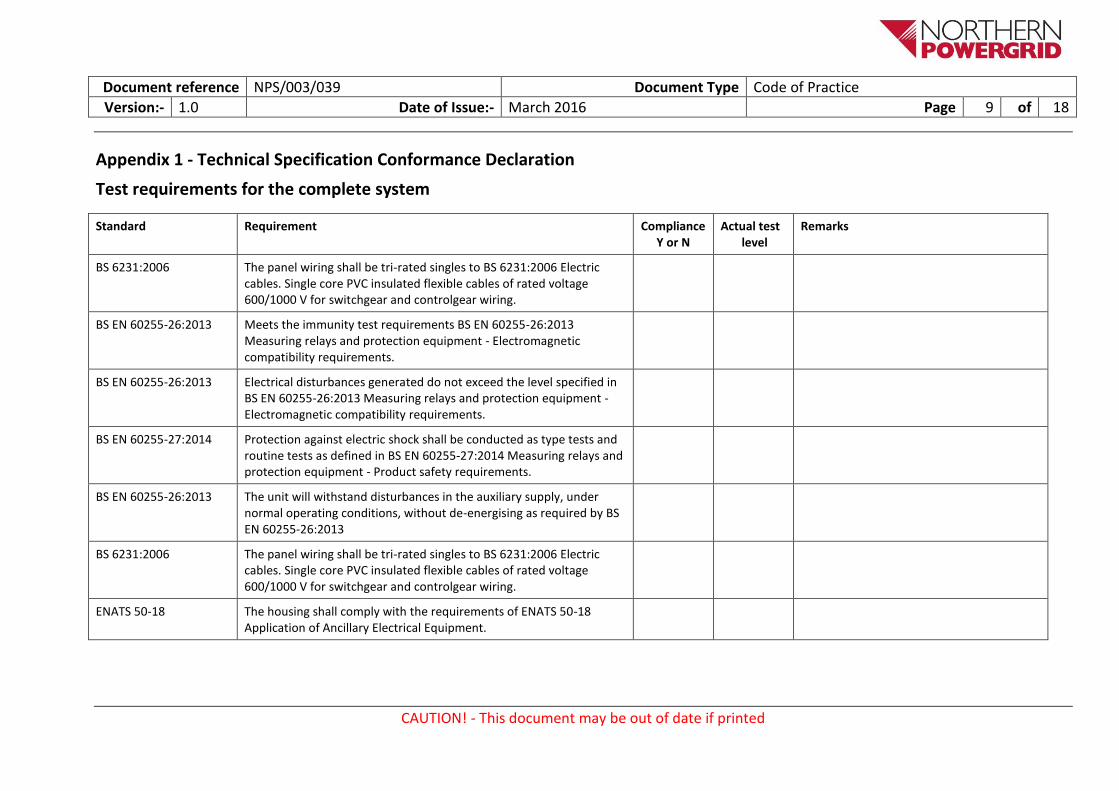
Appendix 1 - Technical Specification Conformance Declaration
Test requirements for the complete system
Standard Requirement Compliance Y or N
Actual test level
Remarks
BS 6231:2006 The panel wiring shall be tri-rated singles to BS 6231:2006 Electric cables. Single core PVC insulated flexible cables of rated voltage 600/1000 V for switchgear and controlgear wiring.
BS EN 60255-26:2013 Meets the immunity test requirements BS EN 60255-26:2013 Measuring relays and protection equipment - Electromagnetic compatibility requirements.
BS EN 60255-26:2013 Electrical disturbances generated do not exceed the level specified in BS EN 60255-26:2013 Measuring relays and protection equipment - Electromagnetic compatibility requirements.
BS EN 60255-27:2014 Protection against electric shock shall be conducted as type tests and routine tests as defined in BS EN 60255-27:2014 Measuring relays and protection equipment - Product safety requirements.
BS EN 60255-26:2013 The unit will withstand disturbances in the auxiliary supply, under normal operating conditions, without de-energising as required by BS EN 60255-26:2013
BS 6231:2006 The panel wiring shall be tri-rated singles to BS 6231:2006 Electric cables. Single core PVC insulated flexible cables of rated voltage 600/1000 V for switchgear and controlgear wiring.
ENATS 50-18 The housing shall comply with the requirements of ENATS 50-18 Application of Ancillary Electrical Equipment.

Document reference NPS/003/039 Document Type Code of Practice
Version:- 1.0 Date of Issue:- March 2016 Page 10 of 18
CAUTION! - This document may be out of date if printed
Standard Requirement Compliance Y or N
Actual test level
Remarks
BS EN 60529 The housing shall be so designed and constructed as to provide minimum ingress protection to classification IP32 in accordance with BS EN 60529.
ENA TS 50-18 Internal wiring shall be ENA TS 50-18 compliant and where this is taken through steel panels shall be suitably and sufficiently protected.

Document reference NPS/003/039 Document Type Code of Practice
Version:- 1.0 Date of Issue:- March 2016 Page 11 of 18
CAUTION! - This document may be out of date if printed
Environmental test requirements for protection and control equipment and systems
Table A.1 — Atmospheric environment requirements
ENA Technical Specification 48-5 Clause
Preferred Standard/Procedure
Specified test level Compliance Y or N
Actual test level
Remarks
5.1 - Temperature cold heat
BS EN 60068-2-1 -10 °C, 96 hours, operate OR -25 °C , 16 hours, operate
-25 °C, 96 hours, storage OR -40 °C, 16 hours, storage
5.1 - Temperature dry heat
BS EN 60068-2-2 +55 °C, 96 hours, operate OR +70 °C, 16 hours, operate
+70 °C, 96 hours, storage
5.2 - Relative humidity BS EN 60068-2-78 93%, 40 °C, 56 days OR
5.2 - Relative humidity (alternative)
BS EN 60068-2-30 93%, 40 °C, 6 off 24 hour cycles of +25 to +55 °C
5.3 – Enclosure BS EN 60529 IP50
Relay components shall be protected to IP50 (dust protected) but the external cabinet shall protect the system to IP32.

Document reference NPS/003/039 Document Type Code of Practice
Version:- 1.0 Date of Issue:- March 2016 Page 12 of 18
CAUTION! - This document may be out of date if printed
Table A.2 — Mechanical environment requirements
ENA Technical Specification 48-5 Clause
Preferred Standard/Procedure
Specified test level Compliance Y or N
Actual test level
Remarks
6.1 – Vibration BS EN 60068-21-1 Response Class 1
Endurance Class 1
6.2 – Shock BS EN 60068-21-2 Response Class 1
Withstand Class 1
6.2 – Bump BS EN 60068-21-2 Class 1
6.3 – Seismic BS EN 60068-21-3 Class 1

Document reference NPS/003/039 Document Type Code of Practice
Version:- 1.0 Date of Issue:- March 2016 Page 13 of 18
CAUTION! - This document may be out of date if printed
Table A.3 — Electrical environmental requirements
ENA Technical Specification 48-5 Clause
Preferred Standard/Procedure
Specified test level Compliance Y or N
Actual test level
Remarks
7.1 - DC supply voltage - 24 V DC
BS EN 60255-1 Table 1, remain within claimed accuracy from 19 to 32 V with >35 V continuous withstand
7.1 - DC supply voltage dips, short interruptions and voltage variations immunity test
BS EN 60255-26 2, 5 & 10 ms interruption, no affect
>10 ms interruption, no maloperation with any reset
15% a.c. ripple
7.1 - DC supply voltage –General
ENA TS 48-5 Ramp up and down over 1 minute, or similar
7.1 - DC Supply voltage -low burden trip relays
ENA TS 48-4 Capacitive Discharge
7.1 - DC supply voltage -high burden trip relays
ENA TS 48-4 Capacitive Discharge
7.2 - AC supply voltage
BS EN 60255-6 Min. and max. declared
Document reference NPS/003/039 Document Type Code of Practice
Version:- 1.0 Date of Issue:- March 2016 Page 14 of 18
CAUTION! - This document may be out of date if printed
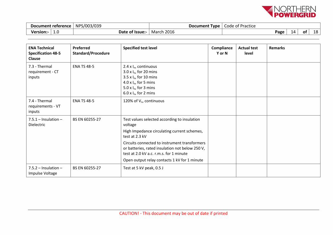
ENA Technical Specification 48-5 Clause
Preferred Standard/Procedure
Specified test level Compliance Y or N
Actual test level
Remarks
7.3 - Thermal requirement - CT inputs
ENA TS 48-5 2.4 x In, continuous 3.0 x In, for 20 mins 3.5 x In, for 10 mins 4.0 x In, for 5 mins 5.0 x In, for 3 mins 6.0 x In, for 2 mins
7.4 - Thermal requirements - VT inputs
ENA TS 48-5 120% of Vn, continuous
7.5.1 – Insulation – Dielectric
BS EN 60255-27 Test values selected according to insulation voltage
High Impedance circulating current schemes, test at 2.3 kV
Circuits connected to instrument transformers or batteries, rated insulation not below 250 V, test at 2.0 kV a.c. r.m.s. for 1 minute
Open output relay contacts 1 kV for 1 minute
7.5.2 – Insulation – Impulse Voltage
BS EN 60255-27 Test at 5 kV peak, 0.5 J
Document reference NPS/003/039 Document Type Code of Practice
Version:- 1.0 Date of Issue:- March 2016 Page 15 of 18
CAUTION! - This document may be out of date if printed
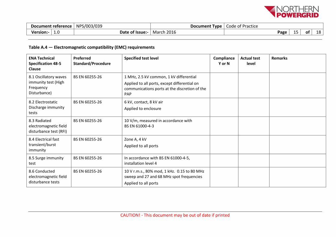
Table A.4 — Electromagnetic compatibility (EMC) requirements
ENA Technical Specification 48-5 Clause
Preferred Standard/Procedure
Specified test level Compliance Y or N
Actual test level
Remarks
8.1 Oscillatory waves immunity test (High Frequency Disturbance)
BS EN 60255-26 1 MHz, 2.5 kV common, 1 kV differential
Applied to all ports, except differential on communications ports at the discretion of the PAP
8.2 Electrostatic Discharge immunity tests
BS EN 60255-26 6 kV, contact, 8 kV air
Applied to enclosure
8.3 Radiated electromagnetic field disturbance test (RFI)
BS EN 60255-26 10 V/m, measured in accordance with BS EN 61000-4-3
8.4 Electrical fast transient/burst immunity
BS EN 60255-26 Zone A, 4 kV
Applied to all ports
8.5 Surge immunity test
BS EN 60255-26 In accordance with BS EN 61000-4-5, installation level 4
8.6 Conducted electromagnetic field disturbance tests
BS EN 60255-26 10 V r.m.s., 80% mod, 1 kHz. 0.15 to 80 MHz sweep and 27 and 68 MHz spot frequencies
Applied to all ports

Document reference NPS/003/039 Document Type Code of Practice
Version:- 1.0 Date of Issue:- March 2016 Page 16 of 18
CAUTION! - This document may be out of date if printed
ENA Technical Specification 48-5 Clause
Preferred Standard/Procedure
Specified test level Compliance Y or N
Actual test level
Remarks
8.7.1 Power frequency magnetic field immunity test
BS EN 61000-4-8 1 000 A/m for 1 sec and 100 A/m for 1 min
Applied to enclosure
8.7.2 Power frequency – General
BS EN 61000-4-16
BS EN 60255-26
Test Level 4, 300 V, 50 Hz common mode
Zone A
8.8 Pulse magnetic field immunity test
BS EN 61000-4-9 6.4/16 µs magnetic pulse, 1 000 A/m
Applied to enclosure
8.9 Damped oscillatory magnetic field immunity test
BS EN 61000-4-10 0.1 and 1.0 MHz, 100 A/m
Applied to enclosure
8.10 Teleprotection equipment of power systems
BS EN 60834-1 &
BS EN 60834-2
Only applicable for teleprotection equipment

Document reference NPS/003/039 Document Type Code of Practice
Version:- 1.0 Date of Issue:- March 2016 Page 17 of 18
CAUTION! - This document may be out of date if printed
ENA Technical Specification 48-5 Clause
Preferred Standard/Procedure
Specified test level Compliance Y or N
Actual test level
Remarks
8.11 Conducted and radiated emission
BS EN 60255-26 Zone A, Conducted, power supply:
0.15 to 0.5 MHz, 79 dB (µV) quasi peak, 66 dB (µV) average
0.5 to 30 MHz, 71dB (µV) quasi peak, 60 dB (µV) average
Radiated, Enclosure at 10 m:
30 to 230 MHz, 40 dB (µV/m) quasi peak,
230 to 1 000 MHz, 47 dB (µV/m) quasi peak
1 Hz to 3 GHz, 56 dB (µV/m) average
3 GHz to 6 GHz, 60 dB (µV/m) average

Document reference NPS/003/039 Document Type Code of Practice
Version:- 1.0 Date of Issue:- March 2016 Page 18 of 18
CAUTION! - This document may be out of date if printed
Appendix 2 – Addendum to Suppliers Requirements Project specific installation and protection requirements will be provided by Primary Engineering Projects for inclusion in this appendix.
Appendix 3 - Pre-commission testing, Routine Inspection and Maintenance requirements
Tenderers shall provide details of the recommended pre-commission testing and inspection required. Details of the Test Voltage Levels, duration, pass/fail criteria, etc. shall be provided. Tenderers shall state any maximum voltage that may be applied or any other limitations that may apply. Tenderers shall provide information regarding detailed and periodic inspection and maintenance requirements to be undertaken during the lifetime of their product.