NPED041 - Network Handover Document Web viewItem Serial Number Part Number Telecom SAP...
25
Document No: NPED041 Version Number 4.0 Publication Date: April 2013 Review Date: Max plus 1 year Type: Handover Template Security Classification: Unclassified Handover ID: NIHXXX (to be assigned by NPE) NPED041 – NETWORK HANDOVER DOCUMENT TEMPLATE Author Network Lab Manager Approver Quality Systems Manager April 2013
Transcript of NPED041 - Network Handover Document Web viewItem Serial Number Part Number Telecom SAP...

Document No: NPED041Version Number 4.0Publication Date: April 2013Review Date: Max plus 1 yearType: Handover TemplateSecurity Classification: UnclassifiedHandover ID: NIHXXX (to be assigned by NPE)
NPED041 – NETWORK HANDOVER DOCUMENT TEMPLATE
AuthorNetwork Lab Manager
Approver Quality Systems Manager
April 2013

Copyright 2023 Telecom New Zealand LimitedAll rights reservedNo part of this publication may be reproduced, stored in a retrieval system, or transmitted in any form or by any means, electronic, mechanical, photocopying, recording or otherwise without the prior written permission of Telecom New Zealand Limited.This document is the property of Telecom New Zealand Limited and may not be disclosed to a third party, other than to any wholly owned subsidiary of Telecom Corporation of New Zealand Limited, or copied without consent.
April 2013 NPED041 2

Table of Contents1. OVERVIEW..........................................................................................51.1. Introduction.........................................................................................................51.1.1 Objectives of Document.......................................................................................51.1.2 Document Background.........................................................................................51.1.3 Instructions for completing this document...........................................................51.1.4 Intended Audience...............................................................................................51.1.5 Related Reference Material..................................................................................51.2. General Installation.............................................................................................61.2.1 General Hardware Information.............................................................................61.3. Application Versions............................................................................................61.4. Non EDS Supported Server..................................................................................61.4.1 Hardware Support................................................................................................61.4.2 OS Support...........................................................................................................71.5. Operating System Support..................................................................................71.6. Application Software Support..............................................................................71.6.1 Software Support Responsibility...........................................................................71.6.2 Application Software Support Contact Details......................................................81.7. Licenses...............................................................................................................81.7.1 Application Licenses.............................................................................................81.7.2 Other Licenses......................................................................................................81.8. Server Network Diagram.....................................................................................81.9. Diagram Detailing Physical Interface Location and Name....................................81.10. Backups...............................................................................................................81.11. Server Addressing...............................................................................................91.12. Server Connections..............................................................................................91.13. Static Routes.......................................................................................................91.14. Application Traffic Flows......................................................................................92. Equipment Installation......................................................102.1. Inventory...........................................................................................................102.2. Node Details......................................................................................................112.3. Management Details..........................................................................................112.3.1 Interface Details.................................................................................................112.3.2 Service Addresses..............................................................................................112.4. Routes and Filters..............................................................................................122.5. Base Configuration............................................................................................122.6. Node Backups....................................................................................................12
April 2013 NPED041 3

2.7. Network Diagram...............................................................................................123. Service Details.................................................................133.1. Service overview...............................................................................................133.2. Service Details...................................................................................................133.2.1 SAM XML Scripts.................................................................................................133.2.2 SAM Templates...................................................................................................133.2.3 Service Pipes......................................................................................................133.2.4 Service VLANs....................................................................................................133.2.5 Service VRFs.......................................................................................................133.2.6 AWS Profiles.......................................................................................................133.2.7 Configuration......................................................................................................133.2.8 MOPS..................................................................................................................133.2.9 Design Document...............................................................................................133.2.10 ERX User Names.................................................................................................133.2.11 ERX User Profiles................................................................................................133.2.12 IP Address Allocations........................................................................................133.2.13 Working configuration........................................................................................143.2.14 Service Verification Tests...................................................................................143.2.15 Test Scripts........................................................................................................14APPENDIX A.............................................................................15A.1 <INSERT NETWORK INTERCONNECTION DIAGRAM HERE>.......................................15A.2 FOR INTERNAL LAB USE ONLY.................................................................................15APPENDIX B : Glossary.............................................................16APPENDIX C: Read Me Document – Change History..................................18
April 2013 NPED041 4

1. OVERVIEW
1.1. Introduction
1.1.1 Objectives of Document
The objectives of this Document are to:Provide a basic template for projects needing to provide handover of NPE Network documentation to the NPE.
1.1.2 Document Background
Background details related to this document, common to all NPE Quality Management Systems Documentation is summarised in NPED002 sections 1.1.2 to 1.1.6 e.g. information on Application/Document Access/Related Reference Material etc.
1.1.3 Instructions for completing this document
This template is a guide only for the basic information that needs to be supplied for handover as a result project implementation into the NPE Network environments. Depending on the Complexity of the deployment additional information may be requested by the NPE management team.
Please don’t amend this document by deleting sections which don’t apply to your projects handover. If you do the integrity of the section numbering of the document are lost
Please don’t embed any supported documents or configuration files into this document. Please supply these documents separately noting the reference to these documents in the appropriate section.
1.1.4 Intended Audience
All users of the NPE Network environments.
1.1.5 Related Reference Material
Although the following documents provide related reference material, they may or may not be referenced directly in this document:
<List details of any Documents referenced in completing this template.>
Document No. Document Title. Document Location.
Comments.
April 2013 NPED041 5

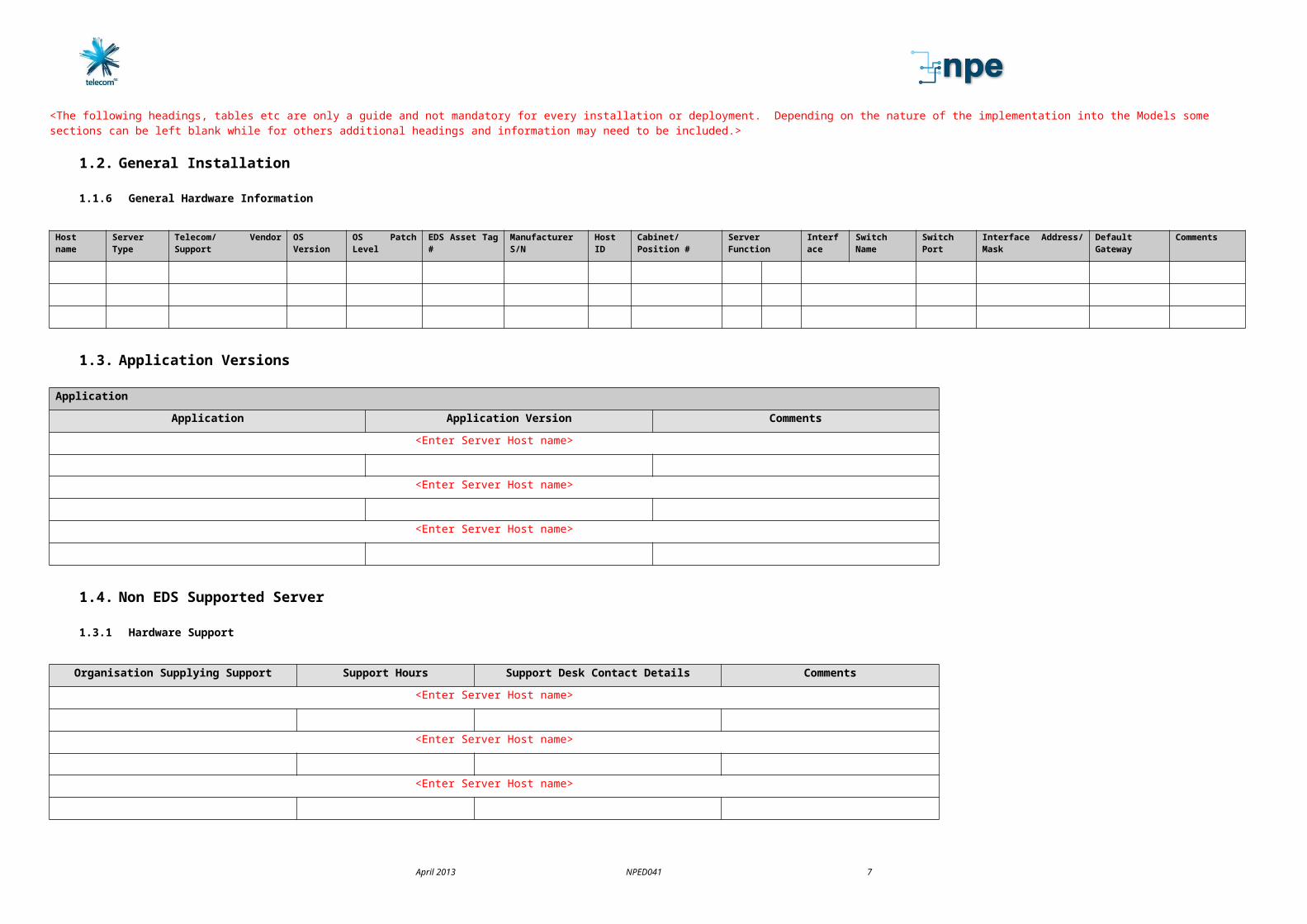
<The following headings, tables etc are only a guide and not mandatory for every installation or deployment. Depending on the nature of the implementation into the Models some sections can be left blank while for others additional headings and information may need to be included.>
1.2. General Installation
1.1.6 General Hardware Information
Host name Server Type Telecom/ Vendor Support OS Version OS Patch Level EDS Asset Tag # Manufacturer S/N Host ID Cabinet/ Position # Server Function Interface
Switch Name Switch Port Interface Address/ Mask Default Gateway
Comments
1.3. Application Versions
ApplicationApplication Application Version Comments
<Enter Server Host name>
<Enter Server Host name>
<Enter Server Host name>
1.4. Non EDS Supported Server
1.3.1 Hardware Support
Organisation Supplying Support Support Hours Support Desk Contact Details Comments<Enter Server Host name>
<Enter Server Host name>
<Enter Server Host name>
April 2013 NPED041 6
1.3.2 OS Support
Organisation Supplying Support
Support Hours Support Desk Contact Details
Comments
<Enter Server Host name>
<Enter Server Host name>
<Enter Server Host name>
1.5. Operating System Support
Organisation Supplying Support
Support Hours Support Desk Contact Details
Comments
<Enter Server Host name>
<Enter Server Host name>
<Enter Server Host name>
Additional details of support Agreements for Non EDS supported servers<Please supply any additional information in relation to support for the servers>
1.6. Application Software Support
1.5.1 Software Support Responsibility
Organisation responsible for providing supportOperating System
Data Bases Application Backups Comments
<Enter Server Host name>
<Enter Server Host name>
<Enter Server Host name>
April 2013 NPED041 7

1.5.2 Application Software Support Contact Details
Organisation Support Hours Support Desk Contact Details
Comments
1.7.Licenses1.6.1 Application Licenses
Application License Type Details of acquiring renewal of Temporary Licenses
<Enter Server Host name>
<Enter Server Host name>
1.6.2 Other Licenses
<Detail any other Licenses associated with the server>
1.8. Server Network Diagram
<Insert Diagram here, N.B a soft copy of the diagram must be supplied in Visio 2003 format>
1.9. Diagram Detailing Physical Interface Location and Name
<Insert a diagram here showing the front/ rear view of the server detailing interface names. These names must be the same as used in the connection details.>
1.10. Backups
<If it is the responsibility of NIL management to maintain system backups then provide details of the backup procedures for the server/s or the name, number and location of the documentation that details the backup procedure.>
1.11.Server Addressing
Interface Address Mask Comment
April 2013 NPED041 8

<Enter Server Host name>
<Enter Server Host name>
1.12. Server Connections
Server Physical Port Name
Interface Name
Speed/Duplex System Name
Switch name & Interface
Comment
<Enter Server Host name>
<Enter Server Host name>
1.13. Static Routes
Destination Mask Gateway Comments/Usage<Enter Server Host name>
<Enter Server Host name>
1.14. Application Traffic Flows
Source Destination Service Comments
April 2013 NPED041 9

2. Equipment Installation
2.1. Inventory
<List all hardware that has been installed into the NIL to support the project infrastructure. This includes cards etc that have been added to existing infrastructure. It includes CLNE, switches routers DSL routers etc.>
Item Serial Number Part Number Telecom SAP Location/Position in Chassis<Node Device Name>
<Node Device Name>
<Node Device Name>
April 2013 NPED041 10

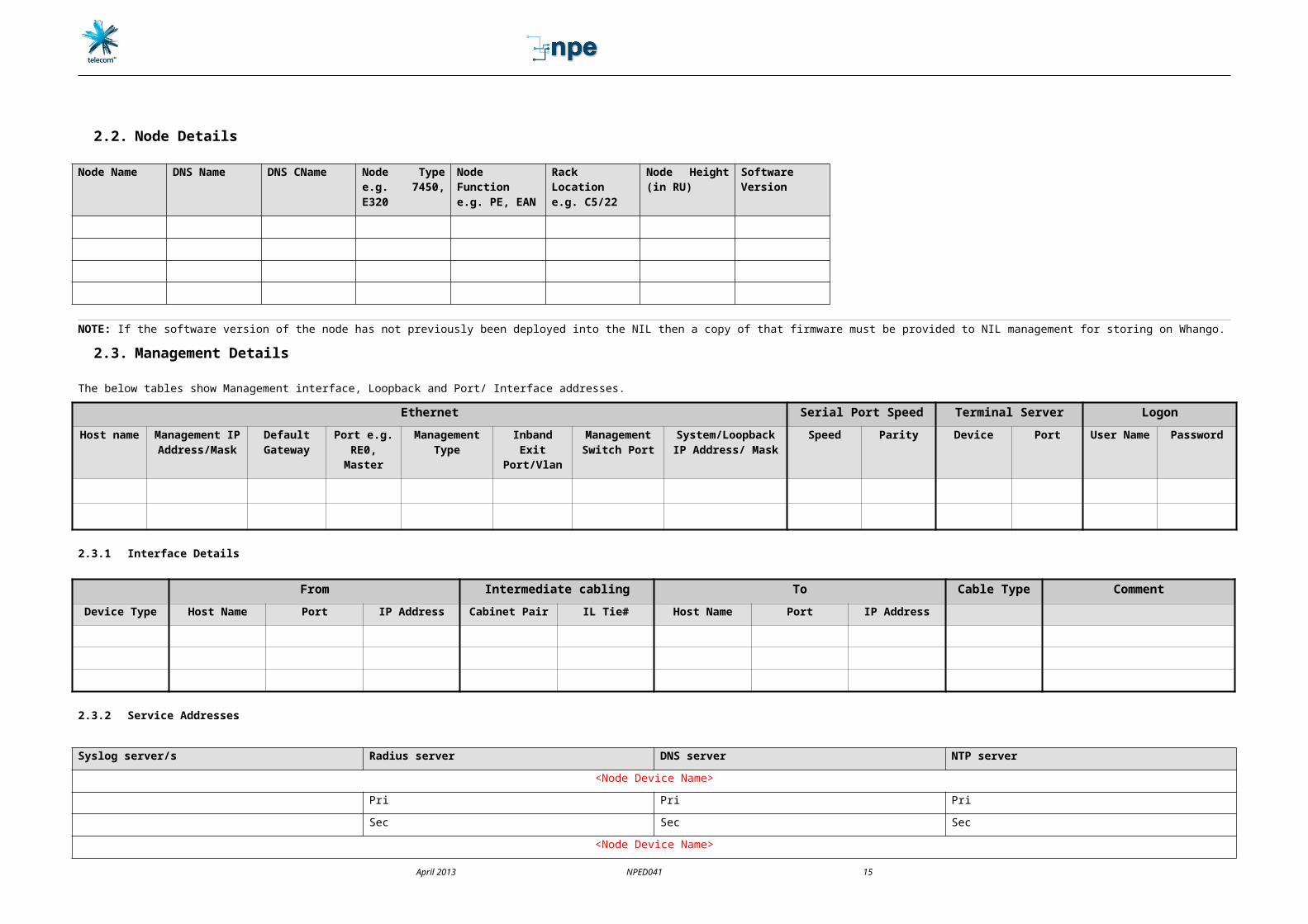
2.2. Node Details
Node Name DNS Name DNS CName Node Type e.g. 7450, E320
Node Function e.g. PE, EAN
Rack Location e.g. C5/22
Node Height (in RU)
Software Version
NOTE: If the software version of the node has not previously been deployed into the NIL then a copy of that firmware must be provided to NIL management for storing on Whango.2.3. Management Details
The below tables show Management interface, Loopback and Port/ Interface addresses.Ethernet Serial Port Speed Terminal Server Logon
Host name
Management IP
Address/Mask
Default Gateway
Port e.g. RE0,
Master
Management Type
Inband Exit
Port/Vlan
Management Switch
Port
System/Loopback IP Address/ Mask
Speed Parity Device Port User Name
Password
2.3.1 Interface Details
From Intermediate cabling To Cable Type CommentDevice Type Host Name Port IP Address Cabinet Pair IL Tie# Host Name Port IP Address
2.3.2 Service Addresses
Syslog server/s Radius server DNS server NTP server<Node Device Name>
Pri Pri PriSec Sec Sec
<Node Device Name>Pri Pri PriSec Sec Sec
April 2013 NPED041 11

2.4. Routes and Filters
<Node Device Name>Static Routes Function
Management Filters Function
<Node Device Name>Static Routes Function
Management Filters Function
2.5. Base Configuration<A soft copy of each Nodes base configuration must be supplied><Insert file name of attached configuration files>
2.6. Node BackupsList Management devices that perform Node backups.
Backup Device Name Backup frequency<Node Device Name>
<Node Device Name>
2.7. Network Diagram
Below is the Network interconnection diagram including touch points into the existing Lab infrastructure. See Appendix xxx for a copy of the Network Diagram.<NOTE: a soft copy in Visio 2003 format must also be provided>
April 2013 NPED041 12

3. Service Details3.1. Service overview
<Provide an overview of the service including a logical diagram showing all the nodes that the service traverses>
3.2. Service Details3.2.1 SAM XML Scripts
<Provide full details of any SAM XML scripts that support the service>3.2.2 SAM Templates
<Provide full details of any SAM Templates that support the service>3.2.3 Service Pipes
<Provide full details of any Epipe ranges, VRF’s etc that have been permanently allocated to the service>
3.2.4 Service VLANs<Provide full details of any VRF’s etc that have been permanently allocated to the service. E.g. traffic and management>
3.2.5 Service VRFs<Provide full details of any Epipe ranges, VRF’s etc that have been permanently allocated to the service>
3.2.6 AWS Profiles<Provide full details of any AWS Profiles, Service Spectrum Profiles. Queues etc that support the service N.B. The actual production Names must be provided. Not those used during testing>
3.2.7 Configuration<Provide full base/ initial configuration details for ALL node, CLNE, switches etc that are required to provision the service. Where script generation tools are used to generate configuration for the likes of CLNE details of the location of these tools must be given. If the tools are new then full details on the use and support must be provided. Also any existing tools must be updated with the service parameters and these parameters included in this documentation>
3.2.8 MOPSAll MOPS supporting this service are referenced in Appendix C.
3.2.9 Design DocumentThe detailed service design is referenced in Appendix C.
3.2.10ERX User Names<Provide full details of any user names that have been provisioned/ configured to support the service>
3.2.11ERX User Profiles<Provide full details of any user profiles that have been provisioned/configured to support the service>
3.2.12 IP Address Allocations<Provide full details of any IP address allocations or pools that have been reserved for this service>
3.2.13Working configurationAt least one working instance of the service must be left in the Model environment.
April 2013 NPED041 13

3.2.14Service Verification Tests
<Provide full details of tests that can be performed to verify that the provisioned service is functioning correctly>
3.2.15Test Scripts< Provide full details of any instrumentation test scripts that were used to verify the service>
April 2013 NPED041 14
APPENDIX A
A.1 <INSERT NETWORK INTERCONNECTION DIAGRAM HERE>
A.2 FOR INTERNAL LAB USE ONLY
Ensure the following systems have been updated:
System Completed/Verified by
NIH number allocatedNagios updated.Rancid updated.DNS updated.IP management Spreadsheets.Equipment Reservation Spreadsheet.Radius.Internal IP address spreadsheet.Interconnectivity Diagram updated.Handover accepted notificationMgt system updated e.g. SAMRack LayoutLabelling on all cables satisfactoryNode Backup’s workingManagement Switch ports configuredNode ports, service config’s etc correctly labelledEquipment back fill received.
April 2013 NPED041 15

APPENDIX B : GlossaryTerm Description Authoriser The person, people or group who will authorise both
the Test Plan and the test finalisationCabling Permanent wiring between items of equipment (as
opposed to Patching – see below)Desktop Zone Physical security zone for connecting laptops and
desktopsGen-I The name of the Telecom Company retailing IS servicesIDN Telecom’s Internal Data NetworkWellington Innovation Centre (WIC)
The Lab situated in Telecom Central, Willis Street, Wellington
Key Stakeholder A person whose decision-making will be affected by the outcome of the project that is the subject of the testing – see also Stakeholder
Legacy Model Any model environment that is actively being retired from the Network
Live Network See Network – used to distinguish the Telecom Network from the Lab simulated network
Mobile Model The model held at Central ExchangeModel See Model NetworkModel Environment Group of Model networks managed by the same model
management team.Model Management Network Provides connections to the management interfaces on
model equipment with in the model environment.Model network Grouping of equipment that models a function/service
of Telecom’s production network but is not connected to the live network.
National Test Lab (TNTL) The lab situated at the Central Exchange Featherston St Wellington that now contains the majority of the operations of the relocated NIL
Network (the) The Telecom Network systems that carry customer generated telecommunication traffic of any type i.e. voice, video, data, signalling etc
Network Security Design and Voice (NSDV)
Telecom group who Design and approve IDN and production data and voice connectivity solutions.
NGB Next Generation BusinessNGN Next Generation NetworkNIL Previous lab environment (Network Integration Lab) at
Tory St Wellington, that has been vacatedNPE The Non Production Environments Team who are
charged with governance over all test environmentsOwner The person responsible for the project, equipment,
document etcPass Phrase A secret phrase which is used to verify the username
presented when connecting/logging in to a device.Patch (contractor) Maintenance and Local Provisioning Patches managed
by service deliveryPatching Non-permanent wiring between items of equipment (as
opposed to Cabling – see above)PTTN Protecting The Telecom Network – refer Doc No 4501PTTL Protecting The Telecom Lab
April 2013 NPED041 16

QA Quality Assurance QAS, QMS Quality Management SystemQC Quality Control – see Quality AssuranceResource Request See “Lab Resource Request”Root See super userSecurity Breach Any event which breaches this policy.Security Threat Any thing that threatens the security of the Labs
network or may lead to a breach of this policy. Service Performance Group A catchall phrase for the group of positions called
Technology Service managers who role is to act as caretaker for the Network
Stakeholder A person who has an interest in, or is affected by, the outcome of the project/testing – see also Key Stakeholder
Sudo rights Sudo is a security mechanism on Unix and Linux box’s which allows the administrator to give users super user rights to specific commands with out giving users full ‘root’ access.
Super User Account This is the account on a device which has complete control over the device including control over user accounts and security.
Syslog Linux/windows log file management systemTelecom Telecom New Zealand Limited and, where applicable,
its related companiesTemplate See “Lab Resource Request” templateTest Environment The NPE operations, including the premises occupied
by NIL and its related operations (eg Central Exchange)Test Environment Admin Network
Administration network used by the Lab management to manage the Lab.
Lab Resident A person whose regular place of work is on Test Environment premises
Lab Resource Request The required form for requesting use of the Labs (NIF001).
Lab User Any person who uses the Lab equipment roomsTest Plan The Test Plan for a specific project, or part of a project,
based on business accepted testing principles.
April 2013 NPED041 17

APPENDIX C: Read Me Document – Change HistoryVersion Description Date1.0 First issue of this document Feb 122.0-3.0 Updated Not recorded4.0 Second issue of this document – Note included
name change of document so clear Network Handover only, new document for IS Handover NPED0042 being introduced.
Apr 13
April 2013 NPED041 18