NPC FULL-BRIDGE TOPOLOGIES FOR … 5, issue 2 dec 2015 ijraet npc full-bridge topologies for...
9
Volume 5, Issue 2 DEC 2015 IJRAET NPC FULL-BRIDGE TOPOLOGIES FOR TRANSFORMERLESS PHOTOVOLTAIC GRID-TIED INVERTERS WITH AN LPF SAMIKERI MAHESH KUMAR M.tech (Power Systems) Anurag Group of Institutions, Hyderabad, Telangana, India B.SOUJANYA YADAV Assistent Professor Anurag Group of Institutions, Hyderabad, Telangana, India. ABSTRACT - Transformer less electrical converter topologies have attracted additional attentions in electrical phenomenon (PV) generation system since they feature high potency and low value. so as to satisfy the security demand for transformer-less grid-tied PV inverters, the escape current needs to be tackled rigorously. Neutral purpose clamped (NPC) topology is an efficient thanks to eliminate the escape current. during this paper, 2 kinds of basic shift cells, the positive neutral purpose clamped cell and also the negative neutral purpose clamped cell, area unit projected to make office topologies, with a scientific technique of topology generation given. Transformers less electrical converter topologies have attracted additional attentions in electrical phenomenon (PV) generation system since they feature high potency and low value. so as to satisfy the security demand for transformer less grid-tied PV inverters, the escape current needs to be tackled rigorously. A family of single-phase transformer less full bridge topologies with low-leakage current for PV grid tied office inverters comes as well as the present oH5 and a few new topologies. a unique positive–negative office (PN-NPC) topology is analyzed very well with operational modes and modulation strategy given. the ability losses area unit compared among the oH5, the full-bridge electrical converter with dc bypass (FB-DCBP) topology, and also the projected PN-NPC topologies. A universal epitome for these 3 NPC-type topologies mentioned is made to judge the topologies at conversion potency and also the escape current characteristic. The PN-NPC topology projected exhibits similar escape current with the FB- DCBP, that is not up to that of the oH5 topology, and options higher potency than each the oH5 and also the FB-DCBP topologies with fuzzy logic controller. I. INTRODUCTION The initial investment and generation cost of PV genera-tion system are still too high compared with other renew able energy sources; thus, the efficiency improvement of grid tied inverters is a significant effort to shorten the payback time and gain the economic benefits faster [1]–[6]. Transformer less grid-tied inverters, such as a full- bridge topology as shown in Fig. 1, have many advantages, e.g., higher efficiency, lower cost smaller size, and weight. vBN may induce a leakage current i Leakage flowing through the loop consisting of the parasitic capacitors (CPV1 and CPV2 ), the filters, the bridge, and the utility grid [7], [8] In an isolated topology, the loop for the leakage current is broken by the transformer, and the leakage current is very low But in a transformer-less topology, the leakage current may be too high to induce serious safety [9] and radiated interference issues [8], [10]. Fig 1: Leakage current in a transformer-less grid-tied PV inverter. However, the common-mode voltage of vAN and therefore, the leakage current must be limited within a reasonable margin. The instantaneous common-mode voltage vCM in the full bridge topology shown in Fig. 1 is represented as follows [7] [10]–[12]: v େ = 0.5(v +v ) (1) where v and v are voltages from mid-point A and B of the bridge leg to terminal N, respectively. In order to eliminate the leakage current, the common- mode voltage vCM must be kept constant during all operation modes and many solutions have been proposed [7], [8], [10]–[22] as follows: 1) Bipolar sinusoidal pulse width modulated (SPWM) full bridge type inverter topologies. The common-mode voltage of this inverter is kept constant during all operating modes [7], [13]. Thus, it features excellent leakage-current characteristics. However, both of the current ripples across the filter inductors and the switching losses are large. Therefore, the unipolar SPWM full-bridge inverters are attractive for its excellent differential mode
Transcript of NPC FULL-BRIDGE TOPOLOGIES FOR … 5, issue 2 dec 2015 ijraet npc full-bridge topologies for...

Volume 5, Issue 2 DEC 2015
IJRAET
NPC FULL-BRIDGE TOPOLOGIES FOR TRANSFORMERLESS PHOTOVOLTAIC GRID-TIED
INVERTERS WITH AN LPF
SAMIKERI MAHESH KUMAR M.tech (Power Systems)
Anurag Group of Institutions, Hyderabad, Telangana, India
B.SOUJANYA YADAV Assistent Professor
Anurag Group of Institutions, Hyderabad, Telangana, India.
ABSTRACT - Transformer less electrical converter topologies have attracted additional attentions in electrical phenomenon (PV) generation system since they feature high potency and low value. so as to satisfy the security demand for transformer-less grid-tied PV inverters, the escape current needs to be tackled rigorously. Neutral purpose clamped (NPC) topology is an efficient thanks to eliminate the escape current. during this paper, 2 kinds of basic shift cells, the positive neutral purpose clamped cell and also the negative neutral purpose clamped cell, area unit projected to make office topologies, with a scientific technique of topology generation given. Transformers less electrical converter topologies have attracted additional attentions in electrical phenomenon (PV) generation system since they feature high potency and low value. so as to satisfy the security demand for transformer less grid-tied PV inverters, the escape current needs to be tackled rigorously. A family of single-phase transformer less full bridge topologies with low-leakage current for PV grid tied office inverters comes as well as the present oH5 and a few new topologies. a unique positive–negative office (PN-NPC) topology is analyzed very well with operational modes and modulation strategy given. the ability losses area unit compared among the oH5, the full-bridge electrical converter with dc bypass (FB-DCBP) topology, and also the projected PN-NPC topologies. A universal epitome for these 3 NPC-type topologies mentioned is made to judge the topologies at conversion potency and also the escape current characteristic. The PN-NPC topology projected exhibits similar escape current with the FB-DCBP, that is not up to that of the oH5 topology, and options higher potency than each the oH5 and also the FB-DCBP topologies with fuzzy logic controller.
I. INTRODUCTION The initial investment and generation cost of
PV genera-tion system are still too high compared with other renew able energy sources; thus, the efficiency improvement of grid tied inverters is a significant effort to shorten the payback time and gain the economic benefits faster [1]–[6]. Transformer less grid-tied inverters, such as a full-bridge topology as shown in Fig. 1, have many advantages, e.g., higher efficiency, lower cost smaller size, and weight. vBN may induce a leakage current i
Leakage flowing through the loop consisting of the parasitic capacitors (CPV1 and CPV2 ), the filters, the bridge, and the utility grid [7], [8] In an isolated topology, the loop for the leakage current is broken by the transformer, and the leakage current is very low But in a transformer-less topology, the leakage current may be too high to induce serious safety [9] and radiated interference issues [8], [10].
Fig 1: Leakage current in a transformer-less grid-tied PV inverter.
However, the common-mode voltage of vAN and therefore, the leakage current must be limited within a reasonable margin. The instantaneous common-mode voltage vCM in the full bridge topology shown in Fig. 1 is represented as follows [7] [10]–[12]:
v = 0.5(v + v ) (1) where v and v are voltages from mid-point A and B of the bridge leg to terminal N, respectively. In order to eliminate the leakage current, the common-mode voltage vCM must be kept constant during all operation modes and many solutions have been proposed [7], [8], [10]–[22] as follows: 1) Bipolar sinusoidal pulse width modulated (SPWM) full bridge type inverter topologies. The common-mode voltage of this inverter is kept constant during all operating modes [7], [13]. Thus, it features excellent leakage-current characteristics. However, both of the current ripples across the filter inductors and the switching losses are large. Therefore, the unipolar SPWM full-bridge inverters are attractive for its excellent differential mode
Gurmeet
Typewritten Text
211

Volume 5, Issue 2 DEC 2015
IJRAET
characteristics such as higher dc-voltage utilization, smaller inductor current ripple and higher power efficiency. 2) Improved unipolar SPWM full-bridge inverters. The conventional unipolar SPWM full-bridge inverter is shown in Fig. 1. In the active modes, the common-mode voltage v is equal to 0.5U .
In the freewheeling modes, v is equal to U or zero depending on the leg mid points (point A and B) connected to the positive or negative terminal of the input. Therefore, the common-mode volt age of conventional unipolar SPWM full-bridge inverter varies at switching frequency, which leads to high-leakage current [7], [13]. To solve this problem, new freewheeling paths need to be built, and they should separate the PV array from the utility grid in freewheeling modes [10]. A solution named highly efficient and reliable inverter concept (HERIC) topology is proposed in [14]. In the freewheeling modes of HERIC inverter, the inductor current flowing through S5 and S6 ; thus, PV array is disconnected from the utility grid. And two extended HERIC topologies are proposed in [15] and [16], respectively. The disconnection can also be located on the dc side of the inverter, such as the H5 topology [17]. Although these topologies mentioned earlier feature the simple circuit structure, the common mode voltage depends on both of the parasitic parameters of the leakage current loop and the voltage amplitude of the utility grid [18], which is not good for the leakage current reduction. To eliminate the leakage current completely, the common mode voltage v should be clamped to half of the input voltage in the freewheeling mode to keep v always constant [12], [19].
As a result, v varies in the dead time, which still induces leakage current [18]. Full-bridge inverter with dc bypass (FB-DCBP) topology proposed in [7] is another solution, as given in Fig. 2(b). It exhibits no dead-time issue mentioned, and the leakage current suppression effect only depends on the turn-on speed of the independent diodes. But FB-DCBP suffers more conduction losses from the inductor current flowing through four switches in the active mode. On the other hand, many power converters, such as dc– dc converters, voltage-source inverters, current-source inverters and multilevel inverters, have been investigated from the basic switching cells to constructing the topology [23]–[28]. Both of the oH5 topology and the FB-DCBP topology can be regarded as the transformerless gird-tied inverters with the same feature of neutral point clamped (NPC). However, these topologies have not
yet been analyzed from the view of topological relationships and switching cells.
In this paper, a systematic method is proposed to generate transformerless grid-tied NPC inverter topologies from two basic switching cells based on the arrangement of the freewheeling routes. And a family of novel NPC inverters is derived with high efficiency and excellent leakage current performance. The paper is organized as follows. In Section II, an NPC switching cell concept is proposed with two basic cells, a positive neutral point clamped cell (P-NPCC) and a negative neutral point clamped cell (N-NPCC), respectively. A family of NPC topologies is generated from the two basic switching cells in Section III. In Section IV, one of the new topologies is analyzed in detail with operational principle, modulation strategy, and power loss com parison with oH5 and FB-DCBP given. Experimental results are presented in Section V, and Section VI concludes the paper.
(a)
(b)
Fig. 2. Some of existing transformer less full-bridge inverter topologies. (a) oH5 [18]. (b) FB-DCBP [7].
Gurmeet
Typewritten Text
212

Volume 5, Issue 2 DEC 2015
IJRAET
Fig 3 Two basic NPC switching cells . (a) P-NPCC. (b) N-NPCC.
II. IDEA OF THE NPCC Based on the survey and analysis in Section
I, the principles of leakage current elimination can be summarized as fol lows: 1) disconnect the PV array from the utility grid in the freewheeling modes with a switch; and 2) let the common mode voltage equal to half of the input voltage in the freewheeling modes with another switch. As a result, two basic NPC switching cells are found with two extra switches mentioned earlier combined with the original power switch to be used to build inverters instead of the original power switch. These two basic NPC switching cells, as shown in Fig.3, are defined as P-NPCC which the clamp switch S3 connected to the mid-point of the bridge with its collector, and N-NPCC which the clamp switch S3 connected to the mid-point of the bridge with its emitter. There are three terminals in both of P-NPCC and N-NPCC: (P+ ) or (N+ ), (P−) or (N−), and (O1 ) or (O2 ). To build a NPC inverter topology with cells mentioned, the following rules should be followed. Rule 2: The P-NPCC has its (P+ ) and (P−) to be connected to the positive terminal of PV array and output filter inductor, respectively. On the other hand, the N-NPCC has its (N−) and (N+ ) to be connected to the negative terminal of PV array and output filter inductor, respectively. Rule 3: One NPCC at least should appear in each bridge leg. Because we have to have three switches to separate grid from the PV array and still maintain the inductor current a loop during freewheeling mode. NPC TRANSFORMERLESS FULL-BRIDGE TOPOLOGIES DERIVED FROM NPCC A. FAMILY OF NOVEL NPC FULL-BRIDGE INVERTERS
The universal topology structure of a single-phase transformerless full-bridge inverter is shown in Fig. 4, where “AU,” “AL,” “BU,” and “BL” are four leg switch modules of the full bridge inverter, respectively. Conventional single-phase full-bridge inverter topology employs single power switch in each switch module. If there is only one P-NPCC or one N-NPCC employed in the inverter, the purpose of disconnecting both the positive and negative terminals of PV array from the utility grid during the freewheeling period can not be achieved. Therefore,
two NPCCs should be employed in phase A and phase B, respectively, the rest still employ the original power switches.
Fig. 4. Universal topology structure of single-phase transformerless full bridge inverter.
As a result, a family of novel single-phase transformer-less full-bridge NPC inverters is generated, as shown in Fig. 5. Fig. 5(a) shows the topology in which modules “AU” and “BL” employ P-NPCC and N-NPCC, respectively. Thus, this topology is named as PN-NPC inverter topology. Fig. 5(b) shows the topology in which modules “AL” and “BU” employ N NPCC and P-NPCC, respectively. So this topology is named as NP-NPC inverter topology. With the same principle, the dual P-NPCC (DP-NPC) and dual N-NPCC (DN-NPC) topologies are shown in Fig. 5(c) and (d), respectively.
Fig. 5. A family of transformer less full-bridge NPC inverter topologies. (a) PN-NPC. (b) NP-NPC. (c) DP-NPC. (d) DN-NPC.
B. OH5 TOPOLOGY GENERATION In Fig. 5(c) and (d), circuit structures of
phase A and phase B are the same. Thus, some of the power switches could be merged. Take the topology shown in Fig. 5(c) as an example for analysis. During the positive half period of the utility grid, SP11 is turned ON in the active mode, while SP21 turned OFF, as shown in Fig. 6(a).
Gurmeet
Typewritten Text
213

Volume 5, Issue 2 DEC 2015
IJRAET
Fig. 6. Modulation strategies for DP-NPC. (a) Primary modulation according to the NPCC switching principle. (b) Improved modulation.
v(P ) = Uv(P ) = v(O) = 0.5U (2)
Due to the blocking of anti-paralleled diodes of S v(P ) and S v(P ) , the topology can still operate normally. Similarly, during the negative half period of the utility grid, SP and SP can be turned ON in the active mode. Dur ing the freewheeling, SP and SP are turned OFF, while SP13 and SP23 over the whole utility grid cycle. Therefore, v(P ) = v(P ) is achieved. According to the analysis above, with the improved modulation strategy shown in Fig. 6(b), the potential of terminals (P )and (P ) are maintained at the same value whether in the active or freewheeling modes. That means terminals (P )and (P )can be connected directly. The redundant switches are removed to simplify the circuit and as a result, the oH5 topology is generated, as shown in Fig. 8(a). To prevent input split capacitor Cdc1 from shortcircuit, there must be a dead time between the drive signals of SP1 and SP2 . Moreover, if the improved modulation strategy shown in Fig. 7 is applied to DN-NPC topology, (N1 ) and (N2 ) can be connected directly. Then, another circuit structure of the oH5 topology is derived, as shown in Fig. 8(b), with the redundant power switches removed.
Fig. 7. Modulation strategies for DN-NPC. Rule 1: Terminal (O1 ) and (O2 ) should be connected to the
neutral point of the input split capacitors and the potential
(a)
(b)
Fig. 8. oH5 topology proposed in [18]. (a) circuit A. (b) circuit B. v(O1) = v(O2) = 0.5UPV . where U is the voltage of PV array. C. FB-DCBP Topology Generated
Fig. 9(a) shows the case where four NPCCs employed as all of the four switch modules. There are two P-NPCCs in “AU” and “BU”, and two N-NPCCs in “AL” and “BL”, respectively. According to the analysis in Section III-B, with an improved modulation strategy, the potentials of terminals (P ) and (P ), (N1 ) and (N2 ) are equal, respectively. Thus, (P ) and (P2 ), (N1 ) and (N2 ) can be connected directly. After the redundant switches are removed, a new topology is obtained, as shown in Fig. 9(b). Where SP 1 and SN 1 are turned ON in the active modes, while SP 1 and SN 1 are turned OFF in the freewheeling modes. Therefore, disconnection of PV array from utility grid during the freewheeling period is realized. Then, SN22 is turned ON during the positive half-period of the utility grid, and SN12 is turned ON during the negative half-period of the utility grid. As a result, the potentials of terminals (P), (N), (A), and (B) are equal during the free wheeling period. If common-mode voltage vCM is higher than that of the terminal (O) in the freewheeling modes, the clamping current flows through the anti paralleled diode of SN 3 and the common-mode voltage vCM is clamped to the half of input voltage. On the other hand, the clamping current flows through the anti paralleled diode of SP 3 when the common-mode voltage vCM lower than
Gurmeet
Typewritten Text
214
Volume 5, Issue 2 DEC 2015
IJRAET
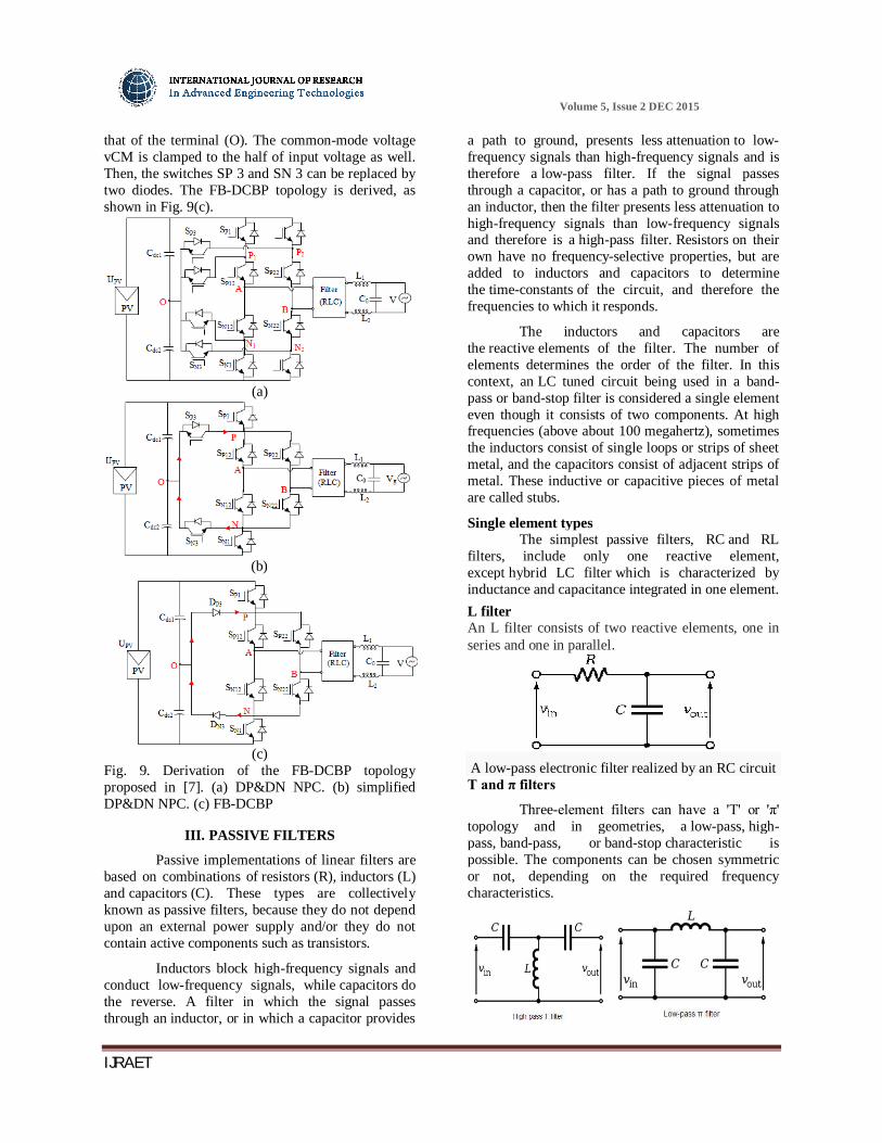
that of the terminal (O). The common-mode voltage vCM is clamped to the half of input voltage as well. Then, the switches SP 3 and SN 3 can be replaced by two diodes. The FB-DCBP topology is derived, as shown in Fig. 9(c).
(a)
(b)
(c)
Fig. 9. Derivation of the FB-DCBP topology proposed in [7]. (a) DP&DN NPC. (b) simplified DP&DN NPC. (c) FB-DCBP
III. PASSIVE FILTERS
Passive implementations of linear filters are based on combinations of resistors (R), inductors (L) and capacitors (C). These types are collectively known as passive filters, because they do not depend upon an external power supply and/or they do not contain active components such as transistors.
Inductors block high-frequency signals and conduct low-frequency signals, while capacitors do the reverse. A filter in which the signal passes through an inductor, or in which a capacitor provides
a path to ground, presents less attenuation to low-frequency signals than high-frequency signals and is therefore a low-pass filter. If the signal passes through a capacitor, or has a path to ground through an inductor, then the filter presents less attenuation to high-frequency signals than low-frequency signals and therefore is a high-pass filter. Resistors on their own have no frequency-selective properties, but are added to inductors and capacitors to determine the time-constants of the circuit, and therefore the frequencies to which it responds.
The inductors and capacitors are the reactive elements of the filter. The number of elements determines the order of the filter. In this context, an LC tuned circuit being used in a band-pass or band-stop filter is considered a single element even though it consists of two components. At high frequencies (above about 100 megahertz), sometimes the inductors consist of single loops or strips of sheet metal, and the capacitors consist of adjacent strips of metal. These inductive or capacitive pieces of metal are called stubs.
Single element types The simplest passive filters, RC and RL
filters, include only one reactive element, except hybrid LC filter which is characterized by inductance and capacitance integrated in one element. L filter An L filter consists of two reactive elements, one in series and one in parallel.
A low-pass electronic filter realized by an RC circuit T and π filters
Three-element filters can have a 'T' or 'π' topology and in geometries, a low-pass, high-pass, band-pass, or band-stop characteristic is possible. The components can be chosen symmetric or not, depending on the required frequency characteristics.
Gurmeet
Typewritten Text
215

Volume 5, Issue 2 DEC 2015
IJRAET
The high-pass T filter in the illustration has very low impedance at high frequencies, and very high impedance at low frequencies. That means that it can be inserted in a transmission line, resulting in the high frequencies being passed and low frequencies being reflected. Likewise, for the illustrated low-pass π filter, the circuit can be connected to a transmission line, transmitting low frequencies and reflecting high frequencies. Using m-derived filter sections with correct termination impedances, the input impedance can be reasonably constant in the pass band.
IV. ANALYSIS ON THE PN-NPC TOPOLOGY AND COMPARISON WITH OTHER NPC
TOPOLOGIES
To analyze the operation principle, the proposed PN-NPC topology is redrawn in Fig. 10.
Fig.10: proposed PN-NPC topology
Fg.11: waveforms of the gate drive signals for the proposed topology
A. OPERATION MODE ANALYSIS
Grid-tied PV systems usually operate with unity power factor. The waveforms of the gate drive signals for the proposed topology are shown in Fig. 11 In Fig. 11, vr is the output signal of inductor current regulator, also named as modulation signal. vgs1 to vgs8 represent the gate drive signals of power switches S1 –S8 , respectively. There are four
operation modes in each period of utility grid, as shown in Fig. 12. In Fig. 12, 푉 is the voltage between terminal A and terminal N, and 푉 the voltage between terminal B and terminal N. 푉 is the differential-mode voltage of the topology, 푉 =푉 − 푉 . 1) Mode I is the active mode in the positive half-period of the utility grid, as shown in Fig. 12(a). S1 , S2 , S5 and S6 are turned ON, and the other switches are turned OFF. 푉 = 푈 and 푉 = 0 ; thus, 푉 = 푈 , and the common mode voltage
푉 = (푉 + 푉 )2 = 0.5푈
2) Mode II is the freewheeling mode in the positive half period of the utility grid, as shown in Fig. 12(b). S2 and S5 are turned ON, the other switches are turned OFF. The inductor current flows through the ant paralleled diode of S7 and S8 . 푉 = 0.5푈 and푉 = 0.5푈 ; thus, 푉 = 0 , and the common-mode voltage
푉 = (푉 + 푉 )2 = 0.5푈
3) Mode III is the active mode in the negative half-period of the utility grid, as shown in Fig. 12(c). S3 , S4, S7, and S8 are turned ON, the other switches are turned OFF. Although S7 and S8 are turned ON, there is no inductor current flowing through these two switches. 푉 = 0 and 푉 = 푈 ; thus, 푉 = −푈 , and the common-mode voltage
푉 = (푉 + 푉 )2 = 0.5푈
Fig. 12. Equivalent circuits of operation modes (a) Active mode in the positive half period. (b) Freewheeling mode in the positive half period. (c) Active mode in the negative half period. (d) Freewheeling mode in the negative half period.
Gurmeet
Typewritten Text
216
Volume 5, Issue 2 DEC 2015
IJRAET
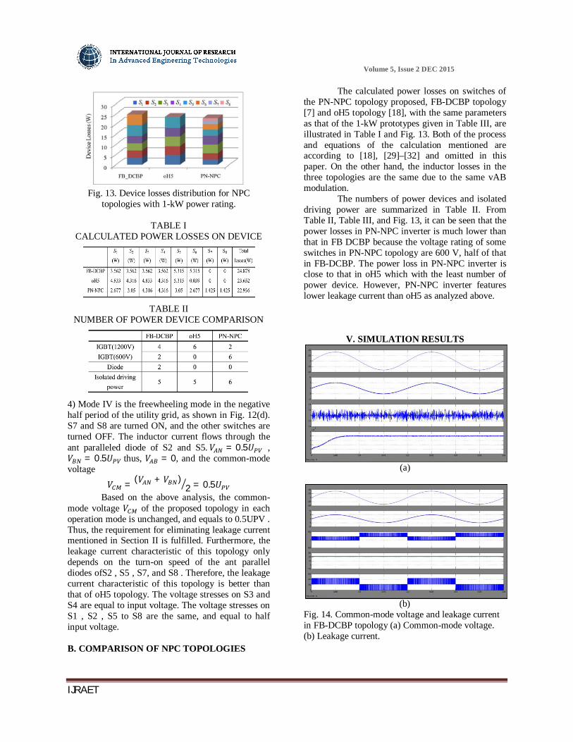
Fig. 13. Device losses distribution for NPC
topologies with 1-kW power rating.
TABLE I CALCULATED POWER LOSSES ON DEVICE
TABLE II
NUMBER OF POWER DEVICE COMPARISON
4) Mode IV is the freewheeling mode in the negative half period of the utility grid, as shown in Fig. 12(d). S7 and S8 are turned ON, and the other switches are turned OFF. The inductor current flows through the ant paralleled diode of S2 and S5. 푉 = 0.5푈 , 푉 = 0.5푈 thus, 푉 = 0, and the common-mode voltage
푉 = (푉 + 푉 )2 = 0.5푈
Based on the above analysis, the common-mode voltage 푉 of the proposed topology in each operation mode is unchanged, and equals to 0.5UPV . Thus, the requirement for eliminating leakage current mentioned in Section II is fulfilled. Furthermore, the leakage current characteristic of this topology only depends on the turn-on speed of the ant parallel diodes ofS2 , S5 , S7, and S8 . Therefore, the leakage current characteristic of this topology is better than that of oH5 topology. The voltage stresses on S3 and S4 are equal to input voltage. The voltage stresses on S1 , S2 , S5 to S8 are the same, and equal to half input voltage. B. COMPARISON OF NPC TOPOLOGIES
The calculated power losses on switches of the PN-NPC topology proposed, FB-DCBP topology [7] and oH5 topology [18], with the same parameters as that of the 1-kW prototypes given in Table III, are illustrated in Table I and Fig. 13. Both of the process and equations of the calculation mentioned are according to [18], [29]–[32] and omitted in this paper. On the other hand, the inductor losses in the three topologies are the same due to the same vAB modulation.
The numbers of power devices and isolated driving power are summarized in Table II. From Table II, Table III, and Fig. 13, it can be seen that the power losses in PN-NPC inverter is much lower than that in FB DCBP because the voltage rating of some switches in PN-NPC topology are 600 V, half of that in FB-DCBP. The power loss in PN-NPC inverter is close to that in oH5 which with the least number of power device. However, PN-NPC inverter features lower leakage current than oH5 as analyzed above.
V. SIMULATION RESULTS
(a)
(b) Fig. 14. Common-mode voltage and leakage current in FB-DCBP topology (a) Common-mode voltage. (b) Leakage current.
Gurmeet
Typewritten Text
217

Volume 5, Issue 2 DEC 2015
IJRAET
(a)
(b)
Fig. 15. Common-mode voltage and leakage current in oH5 topology. (a) Common-mode voltage. (b) Leakage current.
(a)
(b)
Fig. 16. Common-mode voltage and leakage current in PN-NPC topology. (a) Common-mode voltage. (b) Leakage current
CONCLUSION
The PN-NPC topology projected has the subsequent benefits with fuzzy logic and evaluated by experimental results. In this paper, 2 basic change cells, the P-NPCC, and therefore the N-NPCC are projected for the grid-tied electrical converter topology generation to create agency topologies. a scientific methodology of the topology generation has been projected. A family of single part transformer-less full-bridge agency electrical converter topologies with low discharge current supported the essential change cell comes. 1) The common-mode voltage is clamped to a continuing level, that the discharge current are often well suppressed effectively. 2) the superb differential mode characteristic is achieved just like the isolated full-bridge electrical converter with uniploar SPWM. 3) The PN-NPC topology options the simplest conversion potency compared to it of oH5 and FBDCBP. The projected agency topologies even have the aptitude of injecting reactive power, that could be a major advantage of future PV inverters. Therefore, the projected agency topology family is a pretty answer for transformerless grid-tied PV applications.
REFERENCES [1] S. B. Kjaer, J. K. Pederson, and F. Blaabjerg, “A review of single-phase grid-connected inverters for photovoltaic modules,” IEEE Trans. Ind. Appl., vol.41, no. 5, pp. 1292–1306, Sep./Oct. 2005. [2] F. Blaabjerg, Z. Chen, and S. B. Kjaer, “Power electronics as efficient interface in dispersed power generation systems,” IEEE Trans. Power Electron., vol. 19, no. 5, pp. 1184–1194, Sep. 2004. [3] B. Sahan, A. N. Vergara, N. Henze, A. Engler, and P. Zacharias, “A single stage PV module integrated converter based on a low-power current source inverter,” IEEE Trans. Ind. Electron., vol. 55, no. 7, pp. 2602–2609, Jul. 2008. [4] M. Calais, J. Myrzik, T. Spooner, and V. G. Agelidis, “Inverters for single phase grid connected photovoltaic systems—An overview,” in Proc. IEEE Power Electron. Spec. Conf., 2002, vol. 2, pp. 1995–2000. [5] F. Blaabjerg, Z. Chen, and S. B. Kjaer, “Power electronics as efficient interface in dispersed power generation systems,” IEEE Trans. Power Electron., vol. 19, no. 5, pp. 1184–1194, Sep. 2004. [6] Q. Li and P. Wolfs, “A review of the single phase photovoltaic module integrated converter topologies with three different dc link configuration,” IEEE Trans. Power Electron., vol. 23, no. 3, pp. 1320–1333, May. 2008.
Gurmeet
Typewritten Text
218

Volume 5, Issue 2 DEC 2015
IJRAET
[7] R. Gonzalez, J. Lopez, P. Sanchis, and L. Marroyo, “Transformerless inverter for single-phase photovoltaic systems,” IEEE Trans. Power Electron., vol. 22, no. 2, pp. 693–697, Mar. 2007. [8] O. Lopez, F. D. Freijedo, A. G. Yepes, P. Fernandez-Comesana, J. Malvar, R. Teodorescu, and J. Doval-Gandoy, “Eliminating ground current in a transformerless photovoltaic application,” IEEE Trans. Energy Convers., vol. 25, no. 1, pp. 140–147, Mar. 2010. [9] Automatic disconnection device between a generator and the public low voltage grid. VDE Standard 0126-1-1-2006, 2008. [10] H. Xiao and S. Xie, “Leakage current analytical model and application in single-phase transformerless photovoltaic grid-connected inverter,” IEEE Trans. Electromagn. Compat., vol. 52, no. 4, pp. 902–913, Nov. 2010. [11] R. Gonzalez, E. Gubia, J. Lopez, and L. Marroyo, “Transformerless single phase multilevel-based photovoltaic inverter,” IEEE Trans. Ind. Electron., vol. 55, no. 7, pp. 2694–2702, Jul. 2008. [12] H. Xiao and S. Xie, “Transformerless split-inductor neutral point clamped three-level PV grid-connected inverter,” IEEE Trans. Power Electron., vol. 27, no. 4, pp. 1799–1808, Apr. 2012. [13] S. V. Araujo, P. Zacharias, and R. Mallwitz, “Highly efficient single-phase transformerless inverters for grid-connected photovoltaic systems,” IEEE Trans. Ind. Electron., vol. 57, no. 9, pp. 3118–3128, Sep. 2010. [14] S. Heribert, S. Christoph, and K. Jurgen, “Inverter for transforming a DC voltage into an AC current or an AC voltage,” Europe Patent 1 369 985 (A2), May 13, 2003. [15] W. Yu, J. Lai, H. Qian, and C. Hutchens, “High-efficiency mosfet inverter with H6-type configuration for photovoltaic nonisolated ac-module applications,” IEEE Trans. Power Electron., vol. 26, no. 4, pp. 1253–1260,Apr.2011.
SAMIKERI MAHESH KUMAR Completed B.Tech in Electrical & Electronics Engineering in 2012 from Progressive Engineering College Affiliated to JNTUH, Hyderabad and M.Tech in Power Systems in 2015(Perusing) from Anurag Group of Institutions(Formerly Known as
CVSR College of Engineering). Area of interest includes Power systems. E-mail id: [email protected]
B.SOUJANYA YADAV Presently working as Assistent Professor in Anurag Group of Institutions, Hyderabad, Telangana India. He received the B.Tech degree in Electrical & Electronics Engineering from Aurora Engineering College, Hyderabad in 2010. And then completed his P.G in Electrical & Electronics Engineering as Power Systems is specialization at Srinidhi Institute of Science and Technology, Hyderabad in 2012 . His area of interest includes are Renewable Energy Sources(solar), multilevel inverters. He is the life time student member of ISTE. E-mail ID: [email protected]
Gurmeet
Typewritten Text
219


![Triangular Multicarrier SPWM Technique for Nine Level ... · Nabae at el proposed a three-level neutral point clamped (NPC) Inverter [7]. Later, several multilevel topologies have](https://static.fdocuments.us/doc/165x107/5f03ab717e708231d40a3109/triangular-multicarrier-spwm-technique-for-nine-level-nabae-at-el-proposed-a.jpg)