Novitool Aero Press Stand Safety and Operation...
20
Novitool ® Aero ® Press Stand Safety and Operation Manual www.flexco.com www.flexco.com Splicing Press Efficiency in the Fabrication Workshop IMPROPER OR UNSAFE use of this tool can result in serious bodily injury! is manual contains important information about product function and safety. Please read and understand this manual BEFORE operating the tool. Please keep this manual available for other users and owners before they use the tool. is manual should be stored in a safe place. WARNING
Transcript of Novitool Aero Press Stand Safety and Operation...

Novitool® Aero® Press Stand Safety and Operation Manual
www.flexco.comwww.flexco.com
Splicing Press Efficiency in the Fabrication Workshop
IMPROPER OR UNSAFE use of this tool can result in serious bodily injury! This manual contains important information about product function and safety. Please read and understand this manual BEFORE operating the tool. Please keep this manual available for other users and owners before they use the tool. This manual should be stored in a safe place.
WARNING

www.flexco.com
—2—
Table of Contents
Main Components Aero® Press Stand ........................................................ 3
Description ..................................................................................................... 4
Specifications.................................................................................................. 4
Tools Required for Assembly of the Aero® Stand ...................................... 4
General Safety Rules ...................................................................................... 5
Aero® Stand Assembly ................................................................................... 7
Installing the Aero® Press into the Aero Press Stand ..............................16
Operation of the Aero® Press Stand ..........................................................18
Disclaimer The Aero Press Stand has been tested successfully with the Aero® 625, 925, and 1225, along with the Aero 900, 1200, and 1500 models. It is intended for use only with Aero splicing presses manufactured by Flexco and only in these three specific models.

—3—
Main Components Aero® Press Stand
No. Item Code Description Qty No. Item No. Description Qty1 09463 AERO-STD-CW-G3-COLUMN-ASSY 1 14 Q1753 FOOT LEVELING M16 42 09461 AERO-STD-CW-G3-TOPBEAM-ASSY 1 15 08320 AERO-STAND-LOCATING-POST 13 08313 AERO-STAND-BASE 1 16 G1991 SCRW HHCS FLG M8X20 ZN 124 08312 AERO-STAND-CRADLE 1 17 G2027 BOLT HEX FLNG M12X100 ZN 25 GQ865 LIFT-BAR-G2-G3 1 18 C1726 HEX NUT M12-1.75 ZN 26 G2040 SPACER 6MMX16MM ZN 2 19 GQ861 ADAPTER ELEV BRACKET 27 G2037 SCREW SHCS M6X30 ZN 2 20 GQ916 SCRW SHCS M8X20 ZP 48 G2039 NUT NYLOK FLNG M6 ZN 2 21 G2034 PIN-DENTENT-8MMX100 29 G2036 SCRW SHCS M8X35 ZN 5 22 G2026 SCRW HHCS FLG M8X20 ZN 410 G2038 NUT NYLOK FLNG M8 ZN 5 23 GQ875 WHEEL 211 GQ860 CHANNEL LB INTERFACE 2 24 G2050 SCREW HEX FLG M10X20 ZN 112 GR102 PIN DENTENT 9.5MMX75MM ZN 2 25 09203 NUT-T-M8-JEV-508RPS 413 08314 AERO-STAND-CROSSSUPORT 1
22
16
18
16
24
15
14
25
19
4
3
1
2
5
13
17
21
8
10
11
7
9
6
12
23
20

www.flexco.com
—4—
Specifications
DescriptionWith the Aero® Press Stand, you are in possession of a quality Novitool® product from Flexco. The carefully developed and built machine gives you the option of the highest quality conveyor belting fabrication. With the Aero Stand, you can now easily position the the Aero 625, 925, and 1225 as well as the Aero 900, 1200, or 1500 press for fabrication convenience and time savings.
The stand is manufactured from heavy gauge sheet metal to assure stability for continuous press use.
The design allows for the Aero presses to be loaded quickly and conveniently. The lower beam of the Aero is fixed into the stationary cradle of the press stand. The upper beam is connected into the press using cable interface. One person can operate it easily, where movement of the upper half of the press is assisted with counterweights.
Follow the detailed instructions on page 17 to learn how to off load the pressure in the top beam of the press.
Tools Required for Assembly of the Aero® Stand• Ratchet with metric socket set• Metric open end wrench set• Metric hex key set• Adjustable wrench• Channel lock or pliers• Drift punch• Hammer
Aero® Stand Ordering Information
Item Code 09458
Description AERO-STD-CW-G3-625-1225
Dimensions Assembled55" x 44" x 76"(1399 x 1116 x 1930 mm)
Dimensions Working62-74" x 44" x 76"(1583-1883 x 1116 x 1930 mm)
Shipping Weight 365 lbs (165.6 kg)
Carton Dimensions65.5" x 22" x 15"(1664 x 559 x 381 mm)
The Identification plate of the Aero Press Stand is located on the inside of the column assembly door.

Aero Stand Assembly
—5—
Signal words:“DANGER” indicates an imminently hazardous situation which, if not avoided, will result in death or serious injury. This signal word is limited to the most extreme situations.“WARNING” indicates a potentially hazardous situation which, if not avoided, could result in death or serious injury.“CAUTION” indicates a potentially hazardous situation which, if not avoided, may result in minor or moderate injury. It may also be used to alert against unsafe practices.
Safety Symbol
!
This international safety symbol is used to identify and call attention to specific safety matters.
Safety InformationTo Avoid Severe Personal Injury or Property Damage, read carefully and understand the following Safety Precautions.
1. WORK AREA
! CAUTIONKeep your work area clean and well lit.
2. PERSONAL SAFETY
! WARNINGUse safety equipment. Always wear eye protection, gloves, non-skid safety shoes, and adhere to other safety standards of the facility where operating the Aero® Press and Stand.Stay alert, watch what you are doing and use common sense when operating a machine. Do not use machine while tired or under the influence of drugs, alcohol, or medication. A moment of inattention while operating machines may result in serious personal injury.Do not wear loose clothing or jewelry. Keep your hair, clothing, and gloves away from moving parts. Loose clothes, jewelry, or long hair can be caught in moving parts.Abide by all instructions and warning labels.This equipment is not to be used by children or persons with reduced physical, sensory or mental capabilities, or lack of experience and knowledge of the equipment.
General Safety Rules – Save These Instructions–
3. TOOL USE AND CARE
! CAUTIONCheck for misalignment or binding of moving parts, breakage of parts, and any other condition that may affect the tool’s operation. If damaged, have the tool serviced before using. Poorly maintained tools cause many accidents.

www.flexco.com
—6—
5. AERO STAND SAFETY
! DANGERRead and understand the Aero Press operations manual before using the press in the Aero Stand.
! CAUTIONAvoid pinch points during the assembly and in operation. Exercise caution when moving weights or lifting and positioning of components.
Exercise care to avoid unbalanced component conditions during assembly.
Do not cut or kink the lifting cables during handling, assembly, or operation of the Aero Stand.
! WARNINGTwo persons are required for assembly of the Aero Stand. Portions of the process are difficult for one person to perform without risk of injury.
Ensure that Aero Press is secure in stand prior to operation.
Do not move the press stand to a different location while the press is installed.
Do not exceed weight capacity of the Aero Stand cradle. The Aero Stand design is for use only with Aero presses 625, 925, and 1225, and may also accommodate 900, 1200, and 1500.
Ensure that the weight pins are installed securely in the proper position before operating the stand.
Ensure that the vertical column door is closed and latched during operation of the stand.
Avoid raising/lowering of the upper beam with excessive speed.
General Safety Rules -Save These Instructions-
4. SERVICE AND MAINTENANCE
! CAUTIONWhen servicing a tool, use only original replacement parts. Use of unauthorized parts or failure to follow Maintenance Instructions, may create a risk of injury.
Do not wipe plastic parts with solvent. Solvents such as gasoline, thinner, benzene, carbon tetrachloride, and alcohol may damage and crack plastic parts. Do not wipe them with such solvents. Wipe plastic parts with a soft cloth lightly dampened with soapy water and dry thoroughly.
! WARNINGOnly qualified repair personnel must perform tool service. Service or maintenance performed by unqualified personnel could result in a risk of injury.
NEVER use a tool, which is defective or operating abnormally. If the tool appears to be operating unusually, making strange noises, or otherwise appears defective, stop using it immediately and arrange for repairs
Maintain tools with care. Keep machine parts clean. Properly serviced tools are less likely to bind or clutter material and are easier to control.

—7—
www.flexco.com
Aero Stand AssemblyA
With column assembly laying on the floor, open door and remove packing material. Confirm that pins in weight mechanism are to Aero 1225 location. Ensure that all four weights are located to the top and fastened into place with the toggle clamp.
A1
A2
625/1200925/15001225
Ensure jam nuts are positioned onto the threaded shafts of the leveling feet (as shown) before installation. Install two leveling feet (item # 14) into Aero Stand base (item # 3). Ensure leveling feet are fully engaged through mounts.

www.flexco.com
B1
B1
—8—
Aero Stand Assembly
A4
Ensure jam nuts are positioned onto the threaded shafts of the leveling feet (as shown) before installation. Install two leveling feet (item # 14) into cross support assembly (item # 3). Ensure leveling feet are fully engaged through the mounts.
A3
Using six M8 × 20 mm screws (item # 16) assemble base (item # 3) to column assembly (item # 1). Note: Install all screws intially loose, tightening after all are installed.

—9—
Aero Stand Assembly
A6
Using two M12 × 100 mm bolts (item # 17) and two M12 nuts (item # 18) assemble cross support assembly (item # 3) into column assembly (item # 1).
With the weight latch engaged, manually support the weights (position A), remove the pins and lower the weights, taking care to avoid pinch points. Support the remaining (Aero 900) weight (Position A), disengage the weight latch and lower the Aero 900 weight. Avoid pinch points within the weight path!
A5
Weight LatchAERO 900
625/1200
925/1500
1225
A

www.flexco.com
—10—
Aero Stand Assembly
A8
A7
Using six M8 × 20 mm screws (item # 16) assemble cradle (item # 4) to column assembly (item # 1) Note: Install all screws intially loose, tightening after all are installed.
Raise the Aero 900 weight and engage the weight latch. Raise the Aero 625/1200, 925/1500 and 1225 weights and secure them in the uppermost position with the pins. Avoid pinch points within the weight path!
AERO 900
625/1200
925/1500
1225

—11—
Aero Stand Assembly
A10
For use with Aero 900, 1200, or 1500, install locating post (item # 15) into cradle (item # 4) using one M10 × 20 mm screw (item # 24), inserted from below. Position A for Aero 1200 and 1500. Position B for the Aero 900. Post is keyed for proper orientation.
Using four M8 × 30 mm screw (item # 22), install top beam assembly (item # 2) to column assembly (item # 1). Note: Install all screws initially loose, tightening after all are installed.
A9
A
B

www.flexco.com
—12—
Aero Stand Assembly
Inside the column assembly, ensure that the weights are secured with the weight latch. Follow the cables from the pulley located in the top beam from the back side of the Aero Stand assembly for proper positioning. Fix the cables to the weight system using the provided quick link clevises. The cable that runs through the center groove of the pulley should be fastened to the center eyebolt. Follow with the left groove to the left eybolt and right groove to right eyebolt. Take care not to cut, kink, or twist cables. After the cables are installed, ensure that the quick link nuts are secured to close the link.
A11Remove socket head screw and washer. Install wheel (Item # 23). NOTE: during screw torque, use wheel as wrenching device to avoid rotation of the left hand threaded shaft nut. Perform on both sides.
A12
AERO 900
625/1200925/15001225

—13—
Aero Stand Assembly
A14
Install lifting bar (item #5) to the three cables hanging from the top beam assembly using three M8 × 35 mm screws (item # 9) and three M8 nuts (item # 10).
Use two M6 × 30 mm screws (item # 7), two M6 nuts (item # 8), and two 6 mm spacers (item # 6) to secure the umbilical cable extension into the lifting interface.
A13
When using Aero stand for Aero 925 and Aero 1225, reposition lifting bar channel interfaces to each end of the lifting bar.

www.flexco.com
—14—
Aero Stand Assembly
A15Place adapter brackets (Item #19) on Aero® stand cradle. One at the front of the cradle and the other at approximate position of end of press (15a). See photos for positioning of Aero 625 (15b), Aero 925 (15c), and Aero 1225 (15d).
15e
15a
Install M8 x 100 detent pins (Item #21) through holes in adapter bracket tabs on underside of cradle (15e).
15b 15c
15d
Aero 625
Aero1225
Aero 925
Ply 130™ ply separator
—15—
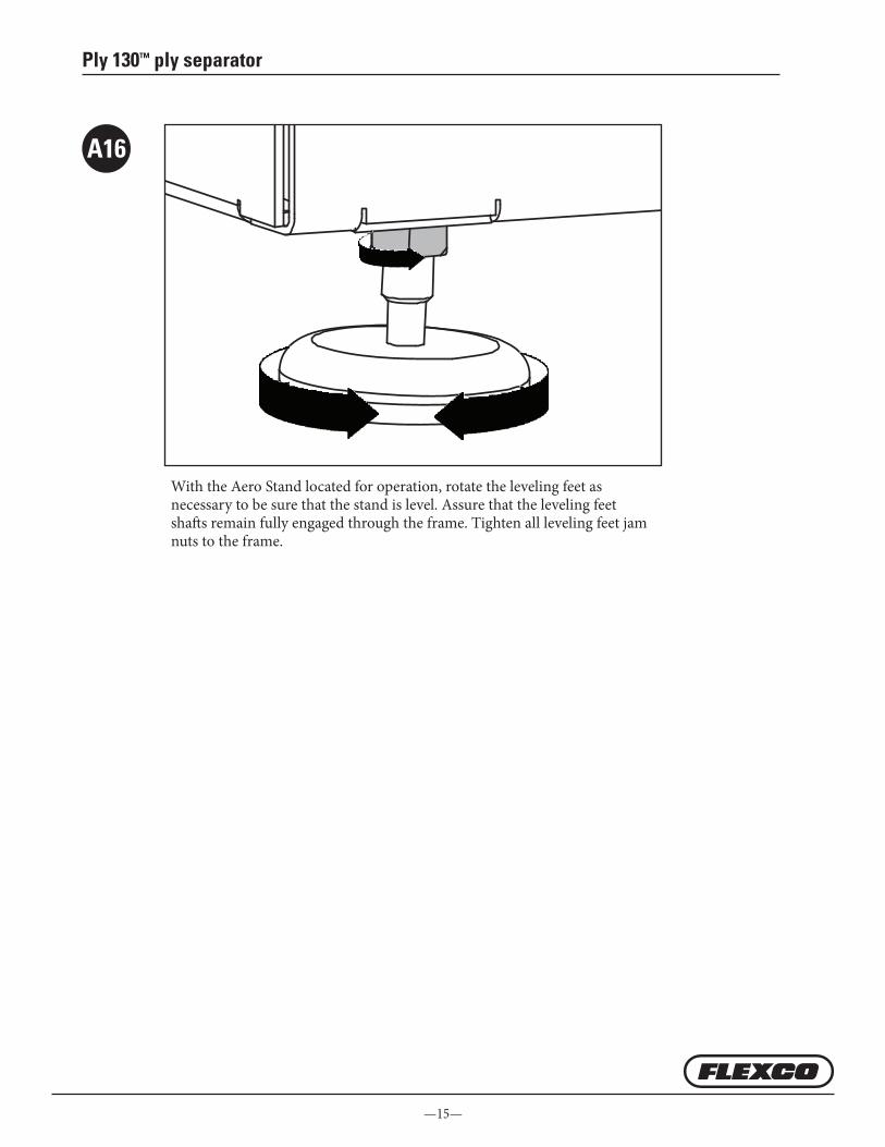
With the Aero Stand located for operation, rotate the leveling feet as necessary to be sure that the stand is level. Assure that the leveling feet shafts remain fully engaged through the frame. Tighten all leveling feet jam nuts to the frame.
A16

www.flexco.com
—16—
B
B1
B2
Installing the Aero Press into the Aero Press Stand
2a 2b
Insert four M8 t-nuts (item # 25) into bottom beam of press extrusion. Screw four M8 x 20 socket screws (item # 20) into the t-nuts to engage the adapter bracket as shown. Install screws (2a and 2b).
Place Aero® Press bottom beam on cradle within the adapter brackets (1a). Place the Aero Press top beam in place and pin to lifting bar using pins. (item # 12) (1b) In weight cabinet, pin the appropriate counterweight for the press placed in the stand. Elevate Aero top beam to determine the ‘suspended’ position, relocate press base if necessary. To lift top press beam the pawl on both sides of the stand beam are to be located in the up position (1c).
1a
1b
1c
—17—
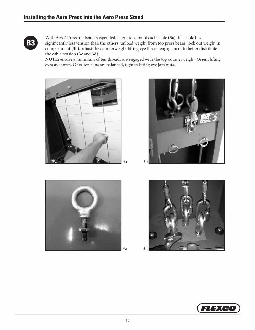
B3
Installing the Aero Press into the Aero Press Stand
With Aero® Press top beam suspended, check tension of each cable (3a). If a cable has significantly less tension than the others, unload weight from top press beam, lock out weight in compartment (3b), adjust the counterweight lifting eye thread engagement to better distribute the cable tension (3c and 3d). NOTE: ensure a minimum of ten threads are engaged with the top counterweight. Orient lifting eyes as shown. Once tensions are balanced, tighten lifting eye jam nuts.
3c 3d
3a 3b
www.flexco.com
—18—
OperationC
The Aero® 625, 925 and 1225 air bladders are located in the upper press beam. It is necessary to “off-load” the counterweight system,
to achieve appropriate set-down of the top beam on the belt to be spliced.
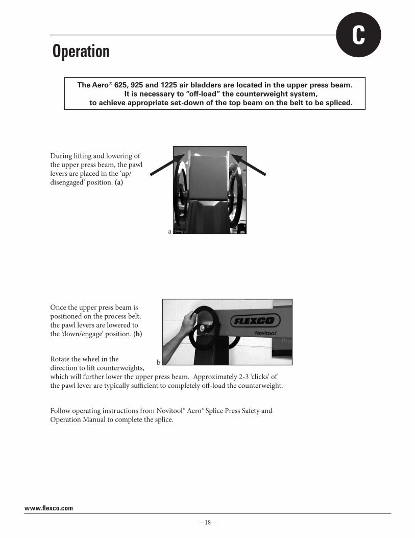
During lifting and lowering of the upper press beam, the pawl levers are placed in the ‘up/disengaged’ position. (a)
a
Once the upper press beam is positioned on the process belt, the pawl levers are lowered to the ‘down/engage’ position. (b)
Rotate the wheel in the direction to lift counterweights, which will further lower the upper press beam. Approximately 2-3 ‘clicks’ of the pawl lever are typically sufficient to completely off-load the counterweight.
Follow operating instructions from Novitool® Aero® Splice Press Safety and Operation Manual to complete the splice.
b

—19—
Operation
Once the splice process is complete, unfasten the press connector bolts.To off-load the top press beam: Grasp the off-load wheel, (c)
Rotate the off-load wheel in the counterweight ‘lift’ direction until the pawl lever is released, (d)
Rotate the pawl lever to the ‘up/disengaged’ position (both pawl levers up), (e)
Lift top press beam with lifting arm attached (f)
d
e
f
! WARNINGDo not use the pawl system to service counterweights.
Use counterweight latch system in cabinet, as well as supplemental lock out methods—blocking/clamping of weights.
c

2525 Wisconsin Avenue • Downers Grove, IL 60515-4200 • USA Tel: (630) 971-0150 • Fax: (630) 971-1180 • E-mail: [email protected]
Visit www.flexco.com for other Flexco locations and products.
©2018 Flexible Steel Lacing Company. 07/25/18. For reorder: X4378