November 2021 - Openreach
36
© British Telecommunications plc Registered Office 81 Newgate Street LONDON EC1A 7AJ Registered in England no.1800000 SIN 517 Issue 3 November 2021 Suppliers’ Information Note For The Openreach Network Single Order Generic Ethernet Access (SOGEA) over VDSL2 and G.fast Service & Interface Description Each SIN is the copyright of British Telecommunications plc. Reproduction of the SIN is permitted only in its entirety, to disseminate information on the BT Network within your organisation. You must not edit or amend any SIN or reproduce extracts. You must not remove BT trademarks, notices, headings or copyright markings. This document does not form a part of any contract with BT customers or suppliers. Users of this document should not rely solely on the information in this document, but should carry out their own tests to satisfy themselves that terminal equipment will work with the BT network. BT reserves the right to amend or replace any or all of the information in this document. BT shall have no liability in contract, tort or otherwise for any loss or damage, howsoever arising from use of, or reliance upon, the information in this document by any person. Due to technological limitations, a very small percentage of customer interfaces may not comply with some of the individual characteristics, which may be defined in this document. Publication of this Suppliers’ Information Note does not give or imply any licence to any intellectual property rights belonging to British Telecommunications plc or others. It is your sole responsibility to obtain any licences, permissions or consents which may be necessary if you choose to act on the information supplied in the SIN. This SIN is available in Portable Document Format (pdf) from: https://www.openreach.co.uk/orpg/home/helpandsupport/sins/sins.do Enquiries relating to this document should be directed to: [email protected]
Transcript of November 2021 - Openreach
© British Telecommunications plc
Registered Office 81 Newgate Street LONDON EC1A 7AJ
Registered in England no.1800000
SIN 517 Issue 3
November 2021
Suppliers’ Information Note
For The Openreach Network
Single Order Generic Ethernet Access (SOGEA) over VDSL2 and G.fast
Service & Interface Description
Each SIN is the copyright of British Telecommunications plc. Reproduction of the SIN is permitted only in its entirety, to disseminate information on the BT Network within your organisation. You must not edit or amend any SIN or reproduce extracts. You must not remove BT trademarks, notices, headings or copyright markings.
This document does not form a part of any contract with BT customers or suppliers.
Users of this document should not rely solely on the information in this document, but should carry out their own tests to satisfy themselves that terminal equipment will work with the BT network.
BT reserves the right to amend or replace any or all of the information in this document.
BT shall have no liability in contract, tort or otherwise for any loss or damage, howsoever arising from use of, or reliance upon, the information in this document by any person.
Due to technological limitations, a very small percentage of customer interfaces may not comply with some of the individual characteristics, which may be defined in this document.
Publication of this Suppliers’ Information Note does not give or imply any licence to any intellectual property rights belonging to British Telecommunications plc or others. It is your sole responsibility to obtain any licences, permissions or consents which may be necessary if you choose to act on the information supplied in the SIN.
This SIN is available in Portable Document Format (pdf) from: https://www.openreach.co.uk/orpg/home/helpandsupport/sins/sins.do Enquiries relating to this document should be directed to: [email protected]
© British Telecommunications plc
Registered Office 81 Newgate Street LONDON EC1A 7AJ
Registered in England no.1800000
Contents
1. SERVICE OUTLINE .................................................................................................................................. 4
1.1 GENERAL ....................................................................................................................................................... 4 1.2 SOGEA NETWORK ARCHITECTURE ............................................................................................................... 4 1.3 THE COPPER PAIR ASSOCIATED TO A SOGEA SERVICE .................................................................................. 5 1.4 CONDITIONS ON THE LINE FROM THE COPPER EXCHANGE .............................................................................. 6 1.5 THE GEA SERVICE TEST AND RAISING A TROUBLE REPORT ........................................................................... 6 1.6 TEST OK ........................................................................................................................................................ 7 1.7 RECOMMENDATIONS FOR IP OR ATA VOICE SERVICES .................................................................................. 7
2. SOGEA OVER VDSL2 INTERFACE DESCRIPTIONS........................................................................ 7
2.1 GEA CABLELINK ........................................................................................................................................... 7 2.1.1 Physical connection ............................................................................................................................. 7 2.1.2 Ethernet Frame Size ............................................................................................................................ 7 2.1.3 VLAN Tagging Options at the GEA Cablelink for SOGEA ................................................................. 7 2.1.4 Ethertype .............................................................................................................................................. 8 2.1.5 Downstream Priority Marking............................................................................................................. 8 2.1.6 Downstream Shaping ........................................................................................................................... 8 2.1.7 Intermediate Agent / DHCP Relay Agent ............................................................................................ 8 2.1.8 Ethernet OAM ...................................................................................................................................... 8 2.1.9 Transparency ....................................................................................................................................... 8 2.1.10 Frame Duplication .......................................................................................................................... 9
2.2 USER NETWORK INTERFACE – GENERAL ....................................................................................................... 9 2.2.1 VDSL2 Rates ........................................................................................................................................ 9 2.2.2 Dynamic Line Management ................................................................................................................. 9 2.2.3 Upstream Shaping ............................................................................................................................... 9 2.2.4 Upstream Priority Marking ................................................................................................................. 9 2.2.5 Modem UNI Port Loopback Testing .................................................................................................... 9
2.3 OPENREACH PROVIDED MODEM PRODUCT VARIANT .................................................................................... 9 2.4 CP PROVIDED MODEM PRODUCT VARIANT ................................................................................................... 9
2.4.1 Physical Network Termination .......................................................................................................... 10 2.4.2 Street Access Physical Realisation .................................................................................................... 14
3. CPE REQUIREMENTS FOR SOGEA OVER VDSL2 ......................................................................... 14
3.1 SCOPE .......................................................................................................................................................... 14 3.2 REQUIREMENTS............................................................................................................................................ 15
3.2.1 Physical Connection .......................................................................................................................... 15 3.2.2 VDSL2 Physical Layer ....................................................................................................................... 15 3.2.3 Ethernet Layer ................................................................................................................................... 15 3.2.4 WAN VLAN Layer .............................................................................................................................. 15 3.2.5 Ethernet OAM .................................................................................................................................... 15 3.2.6 CPE VDSL2 Filter Requirements ...................................................................................................... 15 3.2.7 Supplementary Information ............................................................................................................... 15 3.2.8 Analogue Telephony Adaptor ............................................................................................................ 16 3.2.9 SOGEA/SOGfast Faceplate ............................................................................................................... 16
4. SOGEA OVER G.FAST INTERFACE DESCRIPTIONS .................................................................... 16
4.1 GEA CABLELINK ......................................................................................................................................... 16 4.1.1 Physical connection ........................................................................................................................... 16 4.1.2 Ethernet Frame Size .......................................................................................................................... 16 4.1.3 VLAN Tagging Options at the GEA Cablelink for SOGEA over Gfast .............................................. 16 4.1.4 Ethertype ............................................................................................................................................ 17 4.1.5 Downstream Priority Marking........................................................................................................... 17 4.1.6 Downstream Shaping ......................................................................................................................... 17 4.1.7 Intermediate Agent / DHCP Relay Agent .......................................................................................... 17

© British Telecommunications plc
Registered Office 81 Newgate Street LONDON EC1A 7AJ
Registered in England no.1800000
4.1.8 Ethernet OAM .................................................................................................................................... 17 4.1.9 Transparency ..................................................................................................................................... 18 4.1.10 Frame Duplication ........................................................................................................................ 18
4.2 USER NETWORK INTERFACE – GENERAL ..................................................................................................... 18 4.2.1 G.fast Rates ........................................................................................................................................ 18 4.2.2 Dynamic Line Management ............................................................................................................... 18 4.2.3 Upstream Shaping ............................................................................................................................. 18 4.2.4 Upstream Priority Marking ............................................................................................................... 18 4.2.5 Modem UNI Port Loopback Testing .................................................................................................. 18
4.3 OPENREACH PROVIDED MODEM PRODUCT VARIANT .................................................................................. 18 4.4 CP PROVIDED MODEM PRODUCT VARIANT ................................................................................................. 18
4.4.1 Physical Network Termination .......................................................................................................... 19 4.4.2 Street Access Physical Realisation .................................................................................................... 20
5. CPE REQUIREMENTS FOR SOGEA OVER G.FAST ....................................................................... 20
5.1 SCOPE .......................................................................................................................................................... 20 5.2 REQUIREMENTS............................................................................................................................................ 20
5.2.1 Physical Connection .......................................................................................................................... 20 5.2.2 G.fast Physical Layer......................................................................................................................... 20 5.2.3 Ethernet Layer ................................................................................................................................... 20 5.2.4 WAN VLAN Layer .............................................................................................................................. 20 5.2.5 Ethernet OAM Check variable request/response ............................................................................... 20 5.2.6 CPE G.fast Filter Requirements ........................................................................................................ 20 5.2.7 Supplementary Information ............................................................................................................... 21 5.2.8 Analogue Telephony Adaptor ............................................................................................................ 21 5.2.9 SOGEA/SOGfast VoIP Faceplate ...................................................................................................... 21
6. REFERENCES .......................................................................................................................................... 21
7. ABBREVIATIONS ................................................................................................................................... 23
8. HISTORY PLEASE UPDATE FROM V2.0 ......................................................................................... 24
© British Telecommunications plc
Registered Office 81 Newgate Street LONDON EC1A 7AJ
Registered in England no.1800000
1. Service Outline
1.1 General The information contained in this SIN relates to the launch of SOGEA and the associated changes to engineering policy and practice. It should be noted that the information contained within this SIN might be subject to change. Please check with the https://www.openreach.co.uk/orpg/home/helpandsupport/sins/sins.do site to ensure you have the latest version of this document. Single Order GEA (SOGEA) is a data-only NGA fibre to the cabinet product that is self-contained, hides complexity by including the copper bearer, and can be conveniently purchased through a single order. SOGEA:
• is an addition to the Openreach product portfolio;
• uses the same Ethernet characteristics as currently available from GEA-FTTC products;
• is supplied with its own copper bearer that would terminate in the DSLAM/exchange and not with MPF or WLR equipment;
• is available as a new provide or migration from/to existing products or product combinations;
• accommodates the industry geographic number port process in the order and provision process;
• requires any voice service to be provided entirely by a service provider (e.g. a VoIP service)
• is delivered using VDSL2 or G.fast technology SOGEA is generally expected to be a self-install (PCP-only) provision with CPE Enablement (i.e. CP provided modem/router with either an optional internal or an external ATA). If voice reinjection is required, then an NTE5C with a SOGEA VoIP faceplate must be fitted. The service will not be supported if an Openreach modem is connected in the customer premise. Appointed install options will also be available, including installation of NTE5C and faceplate where required, but will require a CP modem-router. This SIN refers extensively to Openreach SIN498 (GEA-FTTC Service and Interface Specification) [1] and SIN527 (Generic Ethernet Access G.fast (GEA-G.fast) Service and Interface Description)[4].
1.2 SOGEA Network Architecture
The following diagrams show a typical Openreach deployment of SOGEA up to the NTE. This relies on exchange based copper test access.

© British Telecommunications plc
Registered Office 81 Newgate Street LONDON EC1A 7AJ
Registered in England no.1800000
Please note the type of NTE and faceplate may vary (see later). Working service will also require a CP’s own modem-router, not shown here.
1.3 The copper pair associated to a SOGEA service
The copper D-side pair forms part of the working circuit that runs the SOGEA service.
For Day1 product launch,the copper E-side will provide the connectivity back to the exchange for copper test access where needed. Openreach will test the whole circuit from the test head in the exchange to the NTE.
The SOGEA copper pair will have the same specification as detailed in SIN-349 Section 3 entitled ‘MPF Specification’.
SIN-349 Section 5 entitled ‘MPF Section 5 MPF Path Facility Operation’ also applies to SOGEA where the service is ‘out of sync’, and on appointed provision and repair, where a PQT test is run on the full copper circuit. Any DC voltage from the exchange is covered in the next section.

© British Telecommunications plc
Registered Office 81 Newgate Street LONDON EC1A 7AJ
Registered in England no.1800000
1.4 Conditions on the line from the copper exchange With the exception of a temporary parallel running period, there is no dial tone from the exchange on SOGEA lines. A temporary parallel running period can only apply to a migration from a working WLR3-PSTN/LLU-MPF service to SOGEA Any other conditions from the exchange will depend upon the test access solution, tabled as follows:
1.5 The GEA Service Test and raising a trouble report
The GEA Service Test sources multiple parameters and assesses them in real time to determine if there is an anomaly on the service.
Common symptoms of a trouble report, as experienced by customers, are slow speed and modem retrains. However, identical symptoms can also appear intermittently when there is Internet congestion or if the Internet applications require more stability than the current DLM policy provides.
Hence many reports of speed or line stability issues are not actually faults but temporary issues which naturally occur on a contended DSL network.
The GEA Service Test will diagnose a service as faulty if the service test algorithms identify a problem that is most likely to be occurring on the Openreach network. This will allow a GEA1 fault to be accepted by Openreach. If the test can’t diagnose a fault, it may be that DLM has managed the line speed down to achieve the required stability, this is not a fault.
© British Telecommunications plc
Registered Office 81 Newgate Street LONDON EC1A 7AJ
Registered in England no.1800000
Please note current speed, speed relative to previous speeds, and speed relative to eMLC estimates can be impacted by many conditions and it is not a reliable guide that the symptoms are likely to be capable of resolution within the Openreach domain.
1.6 Test OK
Where the GEA Service Test indicates a potential problem with the line, as in the situations described above, the CP can raise a GEA1 fault.
However, in the event that the GEA Service Test returns a PASS result (MFL = OK), but you would still like us to investigate a particular issue on the line; you may raise a GEA3 Visit Assure trouble report. A Visit Assure enables you to appoint an engineer visit to the customer premises to perform further diagnostic activities on the line.
1.7 Recommendations for IP or ATA voice services
SOGEA is a broadband only data product from Openreach. For CPs who choose to host over-IP or ATA based over-the-top voice services, Openreach recommends:
• A choice of ‘Stable’ DLM policy which has the lowest tolerance to errors and retrains;
• avoiding CPE self re-boots on a regular basis;
• a voice codec with a high tolerance of packet loss.
• setting voice packet priority according to 2.1.5
2. SOGEA over VDSL2 Interface Descriptions
This section defines the interface descriptions for SOGEA over VDSL2.
2.1 GEA Cablelink
2.1.1 Physical connection
Requirements as defined in SIN498.
2.1.2 Ethernet Frame Size
Requirements as defined in SIN498.
2.1.3 VLAN Tagging Options at the GEA Cablelink for SOGEA
2.1.3.1 Openreach Added Tags
Requirements as defined in SIN498.
2.1.3.2 CP Added Tags
© British Telecommunications plc
Registered Office 81 Newgate Street LONDON EC1A 7AJ
Registered in England no.1800000
Requirements as defined in SIN498.
2.1.4 Ethertype
Requirements as defined in SIN498.
2.1.5 Downstream Priority Marking
As SIN498 but with the following additional strong recommendation:
The CP should mark downstream voice traffic with PCP code marking 4. This will ensure that, at the VDSL2 port on the street DSLAM, the downstream voice frames are given strict priority over multi-cast packets and other Internet data sent with priority markings of 0 to 3. CPs are also advised to consider that voice frames marked at priority 4 are treated identically to other Internet data sent as priority 4 at the VDSL2 port and the relative rates may have a bearing on the quality of voice services delivered.
2.1.5.1 Per EU / Intra EU frame drop prioritisation
As SIN498 but with the following additional strong recommendation:
In order to ensure that voice frames receive prioritised rate marking, CPs should ensure that frames with PCP code markings of 1 to 4 do not exceed the VDSL2 line rate or the prioritised rate, whichever is lower.
2.1.6 Downstream Shaping
Requirements as defined in SIN498.
2.1.7 Intermediate Agent / DHCP Relay Agent
Requirements as defined in SIN498.
2.1.7.1 Inverted DHCP/PPPoE
Requirements as defined in SIN498.
2.1.8 Ethernet OAM
Requirements as defined in SIN498.
2.1.9 Transparency
Requirements as defined in SIN498.
© British Telecommunications plc
Registered Office 81 Newgate Street LONDON EC1A 7AJ
Registered in England no.1800000
2.1.10 Frame Duplication
Requirements as defined in SIN498.
2.2 User Network Interface – General
2.2.1 VDSL2 Rates
Requirements as defined in SIN498
2.2.2 Dynamic Line Management
Requirements as defined in SIN498.
2.2.3 Upstream Shaping
Requirements as defined in SIN498.
2.2.4 Upstream Priority Marking
The following requirement supersedes the corresponding section in SIN498:
The SOGEA service will NOT be supported over an Openreach provided modem.
Furthermore, the GEA service does not recognise PCP priority code markings upstream. Therefore the CP should ensure that their CPE gives strict priority to upstream voice frames.
Any VLAN tags added to upstream packets shall be treated as payload by the SOGEA service.
2.2.5 Modem UNI Port Loopback Testing
Requirements as defined in SIN498.
2.3 Openreach Provided Modem Product Variant
Not Applicable to SOGEA.
2.4 CP Provided Modem Product Variant
Requirements as defined in SIN498.
Note that support of analogue telephony devices over SOGEA will require a CP’s ATA to be provided with the modem/router, so that analogue telephony devices can be plugged directly into the ATA. In cases where additional devices on home extension wiring need to be fed by the ATA, a special cable is needed to connect the ATA to the voice re-injection socket on the NTE5C SOGEA faceplate (see section 4.4.1). This SOGEA faceplate isolates the voice reinjection voltage from the Openreach network and is required to give reliable service from the ATA on analogue devices.
© British Telecommunications plc
Registered Office 81 Newgate Street LONDON EC1A 7AJ
Registered in England no.1800000
If the customer does not intend to use their extension wiring, then there is no requirement for voice reinjection and hence no need for an SOGEA VoIP faceplate but a standard VDSL2/Gfast SSFP (service Specific Face Plate) is still recommended where home wiring is present.
Non-isolated voice reinjection must not be applied to the Openreach network. This can cause damage to the Openreach network and may put the service at risk of degradation and failure. This is a specific violation of the SOGEA/SOGfast terms and conditions.
2.4.1 Physical Network Termination
Openreach provides a metallic line with a line-box known as a Network Terminating Equipment (NTE). The physical interface is a standard telephone socket on the line box as described in SIN-351 [2] or an RJ45 socket or both, depending on the type of front plate installed.
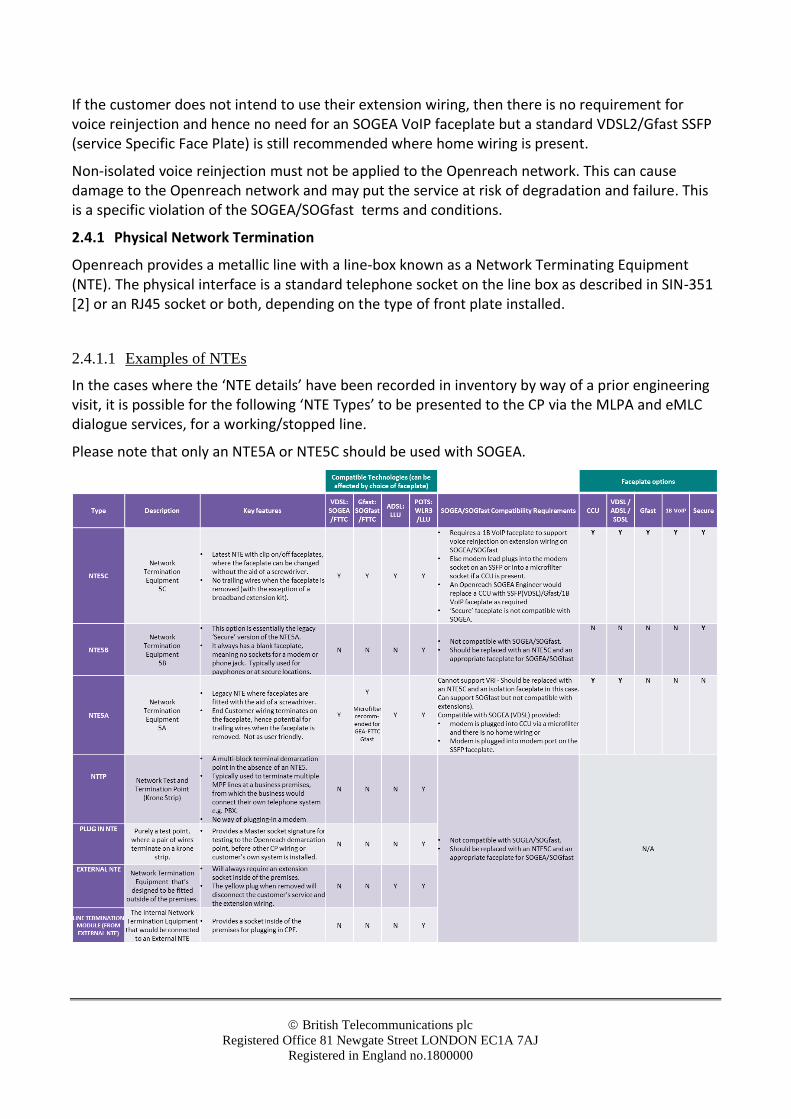
2.4.1.1 Examples of NTEs
In the cases where the ‘NTE details’ have been recorded in inventory by way of a prior engineering visit, it is possible for the following ‘NTE Types’ to be presented to the CP via the MLPA and eMLC dialogue services, for a working/stopped line.
Please note that only an NTE5A or NTE5C should be used with SOGEA.
© British Telecommunications plc
Registered Office 81 Newgate Street LONDON EC1A 7AJ
Registered in England no.1800000
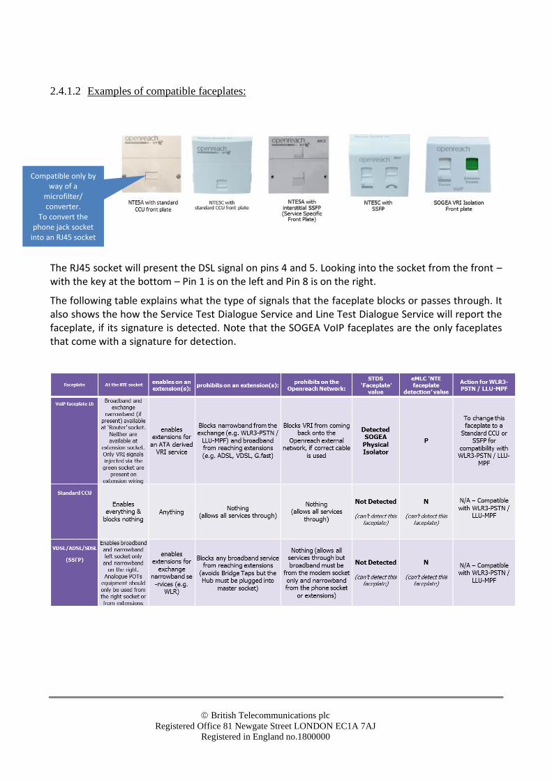
2.4.1.2 Examples of compatible faceplates:
The RJ45 socket will present the DSL signal on pins 4 and 5. Looking into the socket from the front – with the key at the bottom – Pin 1 is on the left and Pin 8 is on the right.
The following table explains what the type of signals that the faceplate blocks or passes through. It also shows the how the Service Test Dialogue Service and Line Test Dialogue Service will report the faceplate, if its signature is detected. Note that the SOGEA VoIP faceplates are the only faceplates that come with a signature for detection.
Compatible only by way of a
microfilter/ converter.
To convert the phone jack socket
into an RJ45 socket

© British Telecommunications plc
Registered Office 81 Newgate Street LONDON EC1A 7AJ
Registered in England no.1800000
2.4.1.3 Typical deployment scenarios without the use of extensions:
2.4.1.3.1 SOGEA without voice over IP (hence no requirement for an ATA (Analogue Telephone Adapter):
Here are two deployment examples, where the customer is using SOGEA without voice over IP (nor ATA voice service over the top of the SOGEA broadband service).
2.4.1.3.2 SOGEA with IP/ATA voice ‘over the top’ VoIP
Here are two more deployment examples (again without the use of extensions), where the CP has chosen to host over IP or ATA voice service ‘over the top’ of the SOGEA broadband service.
2.4.1.4 Typical deployment scenarios with the use of extensions (Voice Re-Injection):
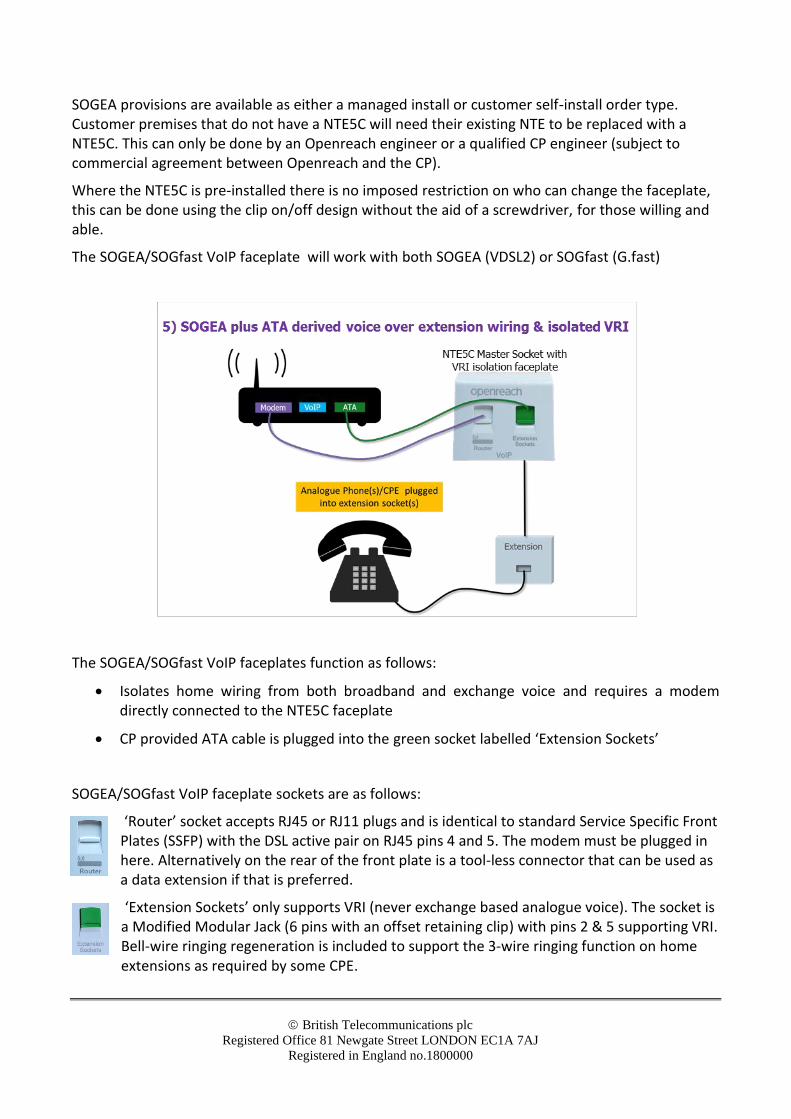
Where the CP has identified that voice reinjection around a customer’s existing home wiring is required, the customer’s NTE must be fitted with a VoIP faceplate to avoid harm to the Openreach network and Customer Experience issues. A SOGEA/SOGfast VoIP faceplate can only be fitted to the new style NTE5C Master Socket back plate.
© British Telecommunications plc
Registered Office 81 Newgate Street LONDON EC1A 7AJ
Registered in England no.1800000
SOGEA provisions are available as either a managed install or customer self-install order type. Customer premises that do not have a NTE5C will need their existing NTE to be replaced with a NTE5C. This can only be done by an Openreach engineer or a qualified CP engineer (subject to commercial agreement between Openreach and the CP).
Where the NTE5C is pre-installed there is no imposed restriction on who can change the faceplate, this can be done using the clip on/off design without the aid of a screwdriver, for those willing and able.
The SOGEA/SOGfast VoIP faceplate will work with both SOGEA (VDSL2) or SOGfast (G.fast)
The SOGEA/SOGfast VoIP faceplates function as follows:
• Isolates home wiring from both broadband and exchange voice and requires a modem directly connected to the NTE5C faceplate
• CP provided ATA cable is plugged into the green socket labelled ‘Extension Sockets’
SOGEA/SOGfast VoIP faceplate sockets are as follows:
‘Router’ socket accepts RJ45 or RJ11 plugs and is identical to standard Service Specific Front Plates (SSFP) with the DSL active pair on RJ45 pins 4 and 5. The modem must be plugged in here. Alternatively on the rear of the front plate is a tool-less connector that can be used as a data extension if that is preferred.
‘Extension Sockets’ only supports VRI (never exchange based analogue voice). The socket is a Modified Modular Jack (6 pins with an offset retaining clip) with pins 2 & 5 supporting VRI. Bell-wire ringing regeneration is included to support the 3-wire ringing function on home extensions as required by some CPE.
© British Telecommunications plc
Registered Office 81 Newgate Street LONDON EC1A 7AJ
Registered in England no.1800000
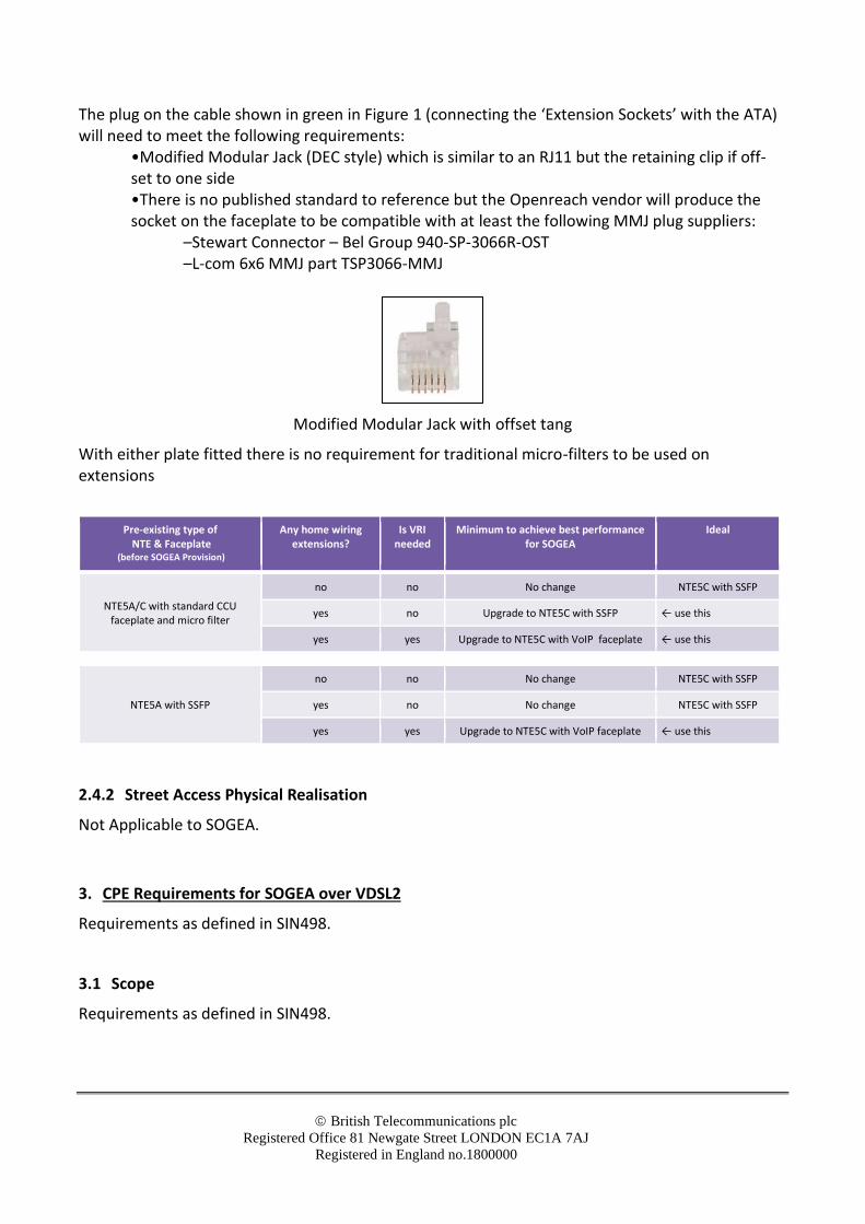
The plug on the cable shown in green in Figure 1 (connecting the ‘Extension Sockets’ with the ATA) will need to meet the following requirements:
•Modified Modular Jack (DEC style) which is similar to an RJ11 but the retaining clip if off-set to one side •There is no published standard to reference but the Openreach vendor will produce the socket on the faceplate to be compatible with at least the following MMJ plug suppliers:
–Stewart Connector – Bel Group 940-SP-3066R-OST –L-com 6x6 MMJ part TSP3066-MMJ
Modified Modular Jack with offset tang
With either plate fitted there is no requirement for traditional micro-filters to be used on extensions
Pre-existing type of NTE & Faceplate
(before SOGEA Provision)
Any home wiring extensions?
Is VRI needed
Minimum to achieve best performance for SOGEA
Ideal
NTE5A/C with standard CCU faceplate and micro filter
no no No change NTE5C with SSFP
yes no Upgrade to NTE5C with SSFP ← use this
yes yes Upgrade to NTE5C with VoIP faceplate ← use this
NTE5A with SSFP
no no No change NTE5C with SSFP
yes no No change NTE5C with SSFP
yes yes Upgrade to NTE5C with VoIP faceplate ← use this
2.4.2 Street Access Physical Realisation
Not Applicable to SOGEA.
3. CPE Requirements for SOGEA over VDSL2
Requirements as defined in SIN498.
3.1 Scope
Requirements as defined in SIN498.
© British Telecommunications plc
Registered Office 81 Newgate Street LONDON EC1A 7AJ
Registered in England no.1800000
3.2 Requirements
Requirements as defined in SIN498.
3.2.1 Physical Connection
Requirements for VDSL2 modem as defined in SIN498. The ATA will require a BT plug to enable it to be connected to the POTS port on the faceplate.
3.2.2 VDSL2 Physical Layer
Requirements as defined in SIN498.
3.2.3 Ethernet Layer
Requirements as defined in SIN498.
3.2.4 WAN VLAN Layer
Requirements as defined in SIN498.
3.2.5 Ethernet OAM
Requirements as defined in SIN498.
3.2.6 CPE VDSL2 Filter Requirements
3.2.6.1 Centralised CPE VDSL2 filter device requirements
Not applicable to SOGEA
3.2.6.2 Distributed CPE VDSL2 Filter Requirements
Requirements as defined in SIN498.
3.2.6.3 Additional Notes About CPE Filters
Requirements as defined in SIN498.
3.2.7 Supplementary Information
Requirements as defined in SIN498.

© British Telecommunications plc
Registered Office 81 Newgate Street LONDON EC1A 7AJ
Registered in England no.1800000
3.2.8 Analogue Telephony Adaptor
If the CP’s equipment contains an ATA and there is any intention or likelihood to connect the ATA to the home wiring to drive additional telephony devices, a SOGEA VoIP faceplate must be fitted as defined in section 2.4.1. This is in order to prevent unexpected and potentially harmful voltages from being passed from the ATA/home wiring to the Openreach network. Openreach is concerned that floating voltages or voltages positive with respect to earth may have a harmful effect on its network.
If the ATA/home wiring is not isolated by use of one of the SOGEA faceplates, problems may occur that prevent the ATA from functioning correctly e.g. off/on–hook detection.
Openreach may deploy test mechanisms to detect and report the use of non-isolated ATA equipment – refer to the SOGEA contract for further information.
3.2.9 SOGEA/SOGfast Faceplate
SOGEA/SOGfast faceplates may contain passive electrical signatures that will allow Openreach to determine which type of faceplate is attached to the circuit. These circuits do not change the electrical properties of the line as defined in SIN349 [3].
CPs should note that the SOGEA VoIP faceplate must be removed and replaced with an appropriate alternative if the service is changed to include standard WLR or MPF. With the SOGEA switched faceplate the is the option to switch into the mode suitable for exchange based voice, and note the telephone will need to be plugged into an extension socket.
NOTE: The NTE5C back-plate contains the standard termination/ringing components across the A/B pair of a 470k Ohm resistor in series with a 1.8µF capacitor, with the bellwire ringing signal being generated at the union between the resistor and capacitor.
4. SOGEA over G.fast Interface Descriptions
This section defines the interface descriptions for SOGEA over G.fast.
4.1 GEA Cablelink
4.1.1 Physical connection
Requirements as defined in SIN527.
4.1.2 Ethernet Frame Size
Requirements as defined in SIN527.
4.1.3 VLAN Tagging Options at the GEA Cablelink for SOGEA over Gfast
4.1.3.1 Openreach Added Tags
Requirements as defined in SIN527.
© British Telecommunications plc
Registered Office 81 Newgate Street LONDON EC1A 7AJ
Registered in England no.1800000
4.1.3.2 CP Added Tags
Requirements as defined in SIN527.
4.1.4 Ethertype
Requirements as defined in SIN527.
4.1.5 Downstream Priority Marking
As SIN527 but with the following additional strong recommendation:
The CP should mark downstream voice traffic with PCP code marking 4. This will ensure that, at the G.fast port on the street DSLAM, the downstream voice frames are given strict priority over multi-cast packets and other Internet data sent with priority markings of 0 to 3. CPs are also advised to consider that voice frames marked at priority 4 are treated at the G.fast port identically to other Internet data sent as priority 4, and the relative rates may have a bearing on the quality of voice services delivered.
4.1.5.1 Per EU / Intra EU frame drop prioritisation
As SIN527 but with the following additional strong recommendation:
In order to ensure that voice frames receive prioritised rate marking, CPs should ensure that frames with PCP code markings of 1 to 4 do not exceed the G.fast line rate or the prioritised rate, whichever is lower.
4.1.6 Downstream Shaping
Requirements as defined in SIN527.
4.1.7 Intermediate Agent / DHCP Relay Agent
Requirements as defined in SIN527.
4.1.7.1 Inverted DHCP/PPPoE
Requirements as defined in SIN527.
4.1.8 Ethernet OAM
Requirements as defined in SIN527. Check variable request/response.
© British Telecommunications plc
Registered Office 81 Newgate Street LONDON EC1A 7AJ
Registered in England no.1800000
4.1.9 Transparency
Requirements as defined in SIN527.
4.1.10 Frame Duplication
Requirements as defined in SIN527.
4.2 User Network Interface – General
4.2.1 G.fast Rates
Requirements as defined in SIN527
4.2.2 Dynamic Line Management
Requirements as defined in SIN527.
4.2.3 Upstream Shaping
Requirements as defined in SIN527.
4.2.4 Upstream Priority Marking
The following requirement supersedes the corresponding section in SIN527:
The SOGfast service will NOT be supported over an Openreach provided modem. Furthermore, the GEA service does not recognise PCP priority code markings upstream. Therefore the CP should ensure that their CPE gives strict priority to upstream voice frames.
Any VLAN tags added to upstream packets shall be treated as payload by the SOGfast service.
4.2.5 Modem UNI Port Loopback Testing
Requirements as defined in SIN527.
4.3 Openreach Provided Modem Product Variant
As per SIN527. CP needs to provide a suitable router/hub.
4.4 CP Provided Modem Product Variant
Requirements as defined in SIN527.
© British Telecommunications plc
Registered Office 81 Newgate Street LONDON EC1A 7AJ
Registered in England no.1800000
Note that support of analogue telephony devices over SOGfast will require either an internal or an external ATA to be included with the modem/router so that the analogue telephony devices can be plugged directly into the ATA. In cases where additional devices on home extension wiring need to be fed by the ATA, a special interface cable is needed to connect the ATA to the voice re-injection socket on the NTE5C VoIPfaceplate will be required. This faceplate isolates the voice reinjection from the Openreach network and is required to give reliable analogue voice service from the ATA.
4.4.1 Physical Network Termination
Requirements as defined under this same topic in the VDSL2 section, with the following exceptions:
4.4.1.1 Examples of compatible faceplates:
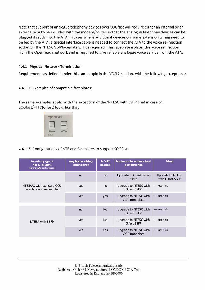
The same examples apply, with the exception of the ‘NTE5C with SSFP’ that in case of SOGfast/FTTC(G.fast) looks like this:
4.4.1.2 Configurations of NTE and faceplates to support SOGfast
Pre-existing type of NTE & Faceplate
(before SOGfast Provision)
Any home wiring extensions?
Is VRI needed
Minimum to achieve best performance
Ideal
NTE5A/C with standard CCU
faceplate and micro filter
no no Upgrade to G.fast micro filter
Upgrade to NTE5C with G.fast SSFP
yes no Upgrade to NTE5C with
G.fast SSFP
← use this
yes yes Upgrade to NTE5C with VoIP front plate
← use this
NTE5A with SSFP
no No Upgrade to NTE5C with G.fast SSFP
← use this
yes No Upgrade to NTE5C with G.fast SSFP
← use this
yes Yes Upgrade to NTE5C with VoIP front plate
← use this
© British Telecommunications plc
Registered Office 81 Newgate Street LONDON EC1A 7AJ
Registered in England no.1800000
4.4.2 Street Access Physical Realisation
Not Applicable to SOGEA.
5. CPE Requirements for SOGEA over G.fast
Requirements as defined in SIN527.
5.1 Scope
Requirements as defined in SIN527.
5.2 Requirements
Requirements as defined in SIN527.
5.2.1 Physical Connection
Requirements for G.fast modem as defined in SIN527.
5.2.2 G.fast Physical Layer
Requirements as defined in SIN527.
5.2.3 Ethernet Layer
Requirements as defined in SIN527.
5.2.4 WAN VLAN Layer
Requirements as defined in SIN527.
5.2.5 Ethernet OAM Check variable request/response
Requirements as defined in SIN527.
5.2.6 CPE G.fast Filter Requirements
5.2.6.1 Centralised CPE G.fast filter device requirements
Requirements as defined in SIN527.
© British Telecommunications plc
Registered Office 81 Newgate Street LONDON EC1A 7AJ
Registered in England no.1800000
5.2.6.2 Distributed CPE G.fast Filter Requirements
Requirements as defined in SIN527.
5.2.6.3 Additional Notes About CPE Filters
Requirements as defined in SIN527.
5.2.7 Supplementary Information
Requirements as defined in SIN527.
5.2.8 Analogue Telephony Adaptor
If the CP equipment contains an ATA and there is any intention or likelihood to connect the ATA to the home wiring to drive additional telephony devices, a VoIP faceplate must be fitted as defined in section 4.4.1. This is in order to prevent unexpected and potentially harmful voltages from being passed from the ATA/home wiring to the Openreach network. Openreach is concerned that floating voltages or voltages positive with respect to earth may have a harmful effect on its network.
If the ATA/home wiring is not isolated by use of one of the VoIP faceplates, problems may occur that prevent the ATA from functioning correctly e.g. off/on–hook detection.
Openreach may deploy test mechanisms to detect and report the use of non-isolated ATA equipment – refer to the SOGfast contract for further information.
5.2.9 SOGEA/SOGfast VoIP Faceplate
SOGEA/SOGfast VoIP faceplates contain a passive electrical signature that will allow Openreach to determine that this type of faceplate is attached to the circuit. These circuits do not change the electrical properties of the line as defined in SIN349 [3].
CPs should note that the SOGEA/SOGfast VoIP faceplate must be removed and replaced with an appropriate alternative if the service is changed to include standard WLR or MPF.
NOTE: The NTE5C back plate contains the standard termination/ringing components across the A/B pair of a 470k Ohm resistor in series with a 1.8µF capacitor, with the bellwire ringing signal being generated at the union between the resistor and capacitor.
6. References
[1] SIN498 Generic Ethernet Access Fibre to the Cabinet (GEA-FTTC) Service and Interface Description
[2] SIN351 BT Public Switched Telephone Network (PSTN): Technical Characteristics Of The Single Analogue Line Interface
[3] SIN349 BT Metallic Path Facility, Interface Description

© British Telecommunications plc
Registered Office 81 Newgate Street LONDON EC1A 7AJ
Registered in England no.1800000
[4] SIN527 Generic Ethernet Access G.fast (GEA-G.fast) Service and Interface Description
For information on where to obtain these referenced documents, please see the document sources list at https://www.openreach.co.uk/orpg/home/helpandsupport/sins/sins.do
© British Telecommunications plc
Registered Office 81 Newgate Street LONDON EC1A 7AJ
Registered in England no.1800000
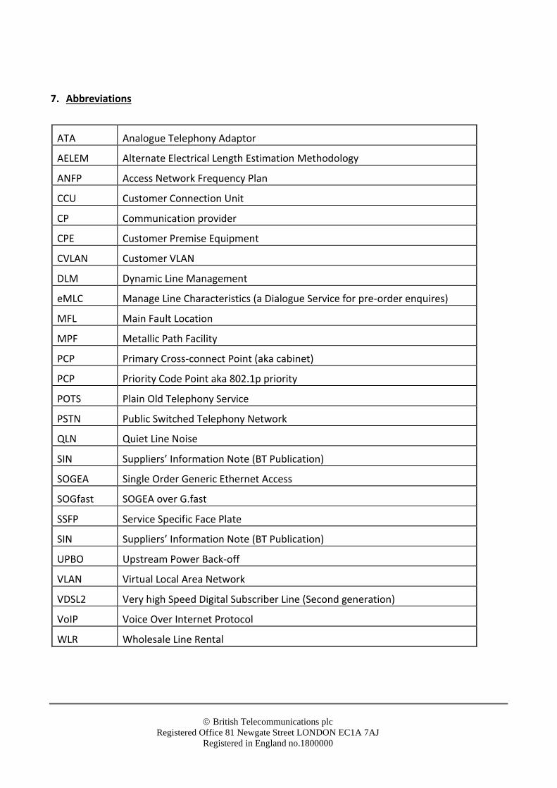
7. Abbreviations
ATA Analogue Telephony Adaptor
AELEM Alternate Electrical Length Estimation Methodology
ANFP Access Network Frequency Plan
CCU Customer Connection Unit
CP Communication provider
CPE Customer Premise Equipment
CVLAN Customer VLAN
DLM Dynamic Line Management
eMLC Manage Line Characteristics (a Dialogue Service for pre-order enquires)
MFL Main Fault Location
MPF Metallic Path Facility
PCP Primary Cross-connect Point (aka cabinet)
PCP Priority Code Point aka 802.1p priority
POTS Plain Old Telephony Service
PSTN Public Switched Telephony Network
QLN Quiet Line Noise
SIN Suppliers’ Information Note (BT Publication)
SOGEA Single Order Generic Ethernet Access
SOGfast SOGEA over G.fast
SSFP Service Specific Face Plate
SIN Suppliers’ Information Note (BT Publication)
UPBO Upstream Power Back-off
VLAN Virtual Local Area Network
VDSL2 Very high Speed Digital Subscriber Line (Second generation)
VoIP Voice Over Internet Protocol
WLR Wholesale Line Rental

© British Telecommunications plc
Registered Office 81 Newgate Street LONDON EC1A 7AJ
Registered in England no.1800000
8. History PLEASE UPDATE FROM V2.0
Issue Date Changes
Issue 1 March 2020 First version of SIN
Issue 3 30/11/2020 Updated following change to Openreach template
Issue 3 02/11/2021 Annual Review – no changes required – issue remains unchanged.
© British Telecommunications plc
Registered Office 81 Newgate Street LONDON EC1A 7AJ
Registered in England no.1800000
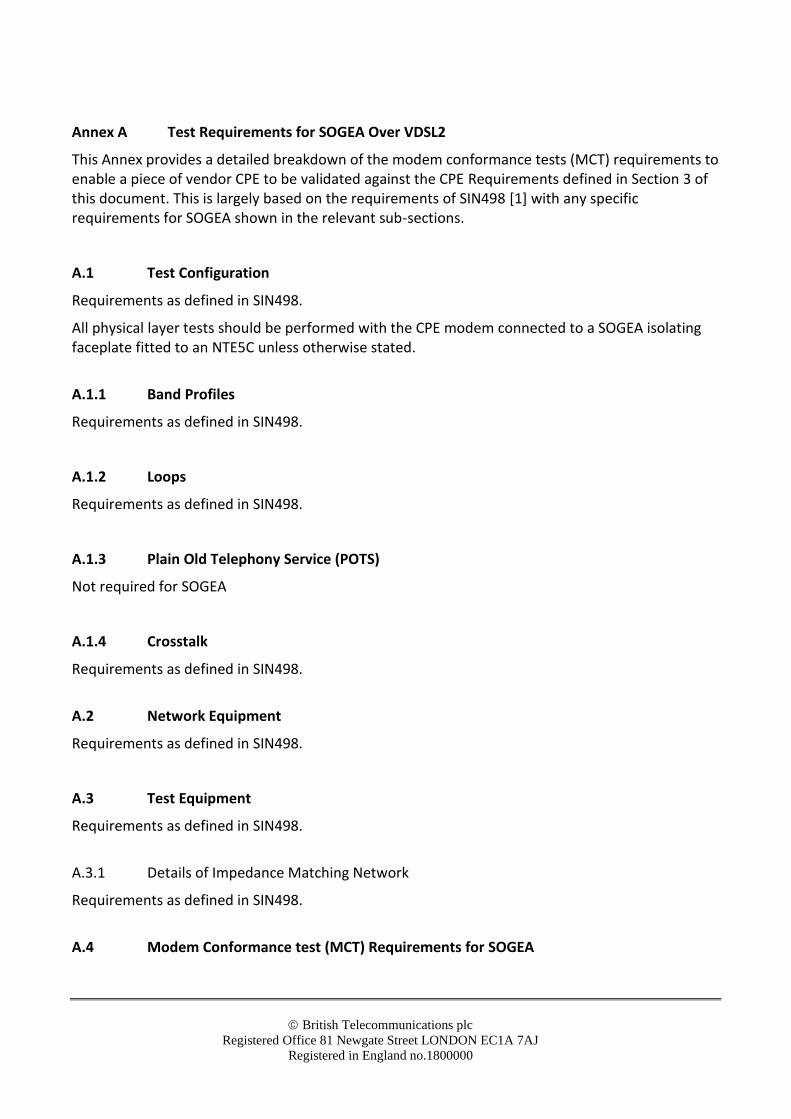
Annex A Test Requirements for SOGEA Over VDSL2
This Annex provides a detailed breakdown of the modem conformance tests (MCT) requirements to enable a piece of vendor CPE to be validated against the CPE Requirements defined in Section 3 of this document. This is largely based on the requirements of SIN498 [1] with any specific requirements for SOGEA shown in the relevant sub-sections.
A.1 Test Configuration
Requirements as defined in SIN498.
All physical layer tests should be performed with the CPE modem connected to a SOGEA isolating faceplate fitted to an NTE5C unless otherwise stated.
A.1.1 Band Profiles
Requirements as defined in SIN498.
A.1.2 Loops
Requirements as defined in SIN498.
A.1.3 Plain Old Telephony Service (POTS)
Not required for SOGEA
A.1.4 Crosstalk
Requirements as defined in SIN498.
A.2 Network Equipment
Requirements as defined in SIN498.
A.3 Test Equipment
Requirements as defined in SIN498.
A.3.1 Details of Impedance Matching Network
Requirements as defined in SIN498.
A.4 Modem Conformance test (MCT) Requirements for SOGEA
© British Telecommunications plc
Registered Office 81 Newgate Street LONDON EC1A 7AJ
Registered in England no.1800000
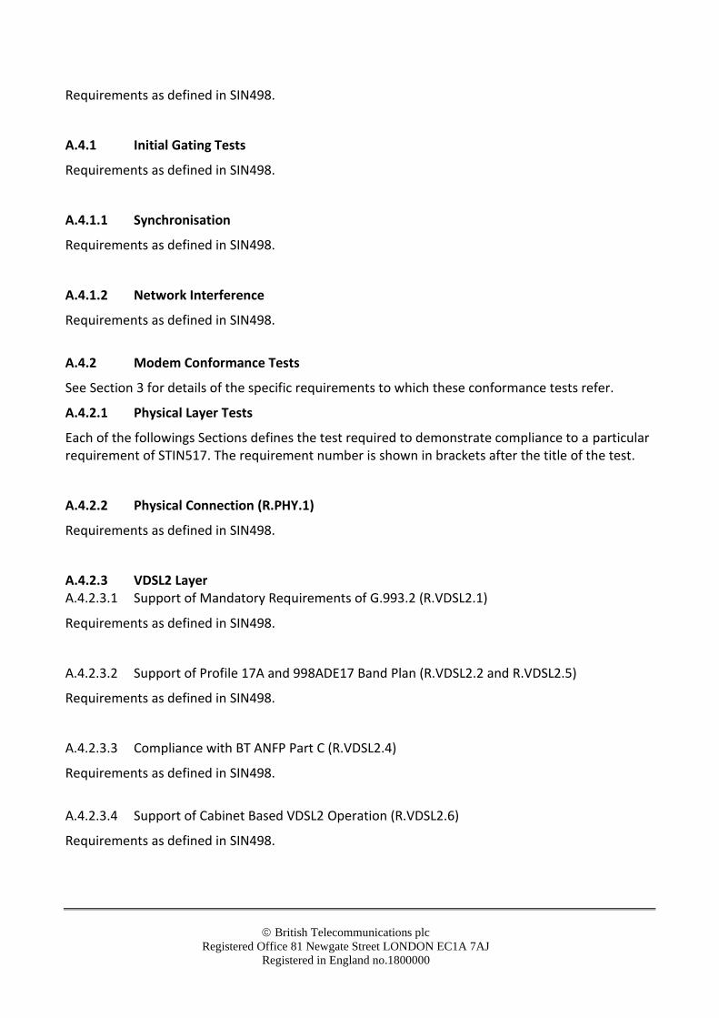
Requirements as defined in SIN498.
A.4.1 Initial Gating Tests
Requirements as defined in SIN498.
A.4.1.1 Synchronisation
Requirements as defined in SIN498.
A.4.1.2 Network Interference
Requirements as defined in SIN498.
A.4.2 Modem Conformance Tests
See Section 3 for details of the specific requirements to which these conformance tests refer.
A.4.2.1 Physical Layer Tests
Each of the followings Sections defines the test required to demonstrate compliance to a particular requirement of STIN517. The requirement number is shown in brackets after the title of the test.
A.4.2.2 Physical Connection (R.PHY.1)
Requirements as defined in SIN498.
A.4.2.3 VDSL2 Layer A.4.2.3.1 Support of Mandatory Requirements of G.993.2 (R.VDSL2.1)
Requirements as defined in SIN498.
A.4.2.3.2 Support of Profile 17A and 998ADE17 Band Plan (R.VDSL2.2 and R.VDSL2.5)
Requirements as defined in SIN498.
A.4.2.3.3 Compliance with BT ANFP Part C (R.VDSL2.4)
Requirements as defined in SIN498.
A.4.2.3.4 Support of Cabinet Based VDSL2 Operation (R.VDSL2.6)
Requirements as defined in SIN498.
© British Telecommunications plc
Registered Office 81 Newgate Street LONDON EC1A 7AJ
Registered in England no.1800000
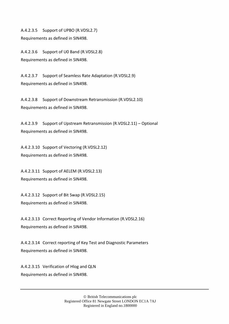
A.4.2.3.5 Support of UPBO (R.VDSL2.7)
Requirements as defined in SIN498.
A.4.2.3.6 Support of U0 Band (R.VDSL2.8)
Requirements as defined in SIN498.
A.4.2.3.7 Support of Seamless Rate Adaptation (R.VDSL2.9)
Requirements as defined in SIN498.
A.4.2.3.8 Support of Downstream Retransmission (R.VDSL2.10)
Requirements as defined in SIN498.
A.4.2.3.9 Support of Upstream Retransmission (R.VDSL2.11) – Optional
Requirements as defined in SIN498.
A.4.2.3.10 Support of Vectoring (R.VDSL2.12)
Requirements as defined in SIN498.
A.4.2.3.11 Support of AELEM (R.VDSL2.13)
Requirements as defined in SIN498.
A.4.2.3.12 Support of Bit Swap (R.VDSL2.15)
Requirements as defined in SIN498.
A.4.2.3.13 Correct Reporting of Vendor Information (R.VDSL2.16)
Requirements as defined in SIN498.
A.4.2.3.14 Correct reporting of Key Test and Diagnostic Parameters
Requirements as defined in SIN498.
A.4.2.3.15 Verification of Hlog and QLN
Requirements as defined in SIN498.
© British Telecommunications plc
Registered Office 81 Newgate Street LONDON EC1A 7AJ
Registered in England no.1800000
A.4.2.4 Ethernet Layer A.4.2.4.1 Ethernet Frame Size (R.ETH.1)
Requirements as defined in SIN498.
A.4.2.5 WAN/VLAN Layer A.4.2.5.1 Support of IEEE 802.1Q VLAN Encapsulation (R.WAN.1)
Requirements as defined in SIN498.
A.4.2.5.2 Ingress Frames Encapsulated Within IEEE 802.1Q VLAN (R.WAN.2)
Requirements as defined in SIN498.
A.4.2.5.3 Simultaneous Support of Multicast and Unicast over the same VLAN (R.WAN.3)
Requirements as defined in SIN498.
A.4.2.5.4 Ethertype Field of Ethernet Frame Set to 0x8100 on Ingress to Openreach UNI (R.WAN.4)
Requirements as defined in SIN498.
A.4.2.5.5 CVLAN Canonical Format Indicator Set to 0 on Ingress to Openreach UNI (R.WAN.5)
Requirements as defined in SIN498.
A.4.2.5.6 VLAN ID Set to 101 (R.WAN.6)
Requirements as defined in SIN498.
A.4.2.5.7 IGMP Reports Encoded Correctly (R.WAN.7)
Requirements as defined in SIN498.
A.4.2.5.8 Multicast Frames Detected and Processed Correctly (R.WAN.9)
Requirements as defined in SIN498.
A.4.2.6 OAM Layer A.4.2.6.1 Support of Loop Back Messages (R.OAM.2)
© British Telecommunications plc
Registered Office 81 Newgate Street LONDON EC1A 7AJ
Registered in England no.1800000
Requirements as defined in SIN498.
A.4.2.6.2 Support of 802.3AH Loopback (R.OAM.3)
Requirements as defined in SIN498.
A.4.2.6.3 Support of ‘Dying Gasp’ (R.OAM.4)
Requirements as defined in SIN498.
A.4.2.6.4 Correct Reporting of Key test and Diagnostic Parameters (R.VDSL2.17)
Requirements as defined in SIN498.
A.4.2.7 CPE Filters
R.FILTER.1 Centralised Splitters
Not Applicable to SOGEA
R.FILTER.2 Distributed Splitters (i.e. micro-filters)
Requirements as defined in SIN498.
A.4.3 SOGEA Testing A.4.3.1 Transmission Performance Testing
In addition to the tests defined above, the transmission performance of the CPE will also need to be measured against the current Live GEA reference models. This will involve the modem performance being evaluated with the DSLAM configured to implement both fast and retransmission profiles.
A.4.3.1.1 Deployment Scenario 1 - CPE plugged directly into NTE5C
Description – This test gives an indication of how a SOGEA CPE would perform if connected to the Openreach GEA network as part of a SSFP based deployment scenario (i.e. no home wiring). It is also used to record a bench-mark of the CPE modem’s performance against the current (i.e. LIVE) network firmware which can then be used to check whether the transmission performance of the CPE modem is adversely affected by future network upgrades. Testing should be performed using both FAST and RETRANSMISSION operation.
Test Description (FAST) –
1. Configure DSLAM to implement an ESEL value of 30dB and the default band profile
(O2_0_6_36_1_6_18_1).
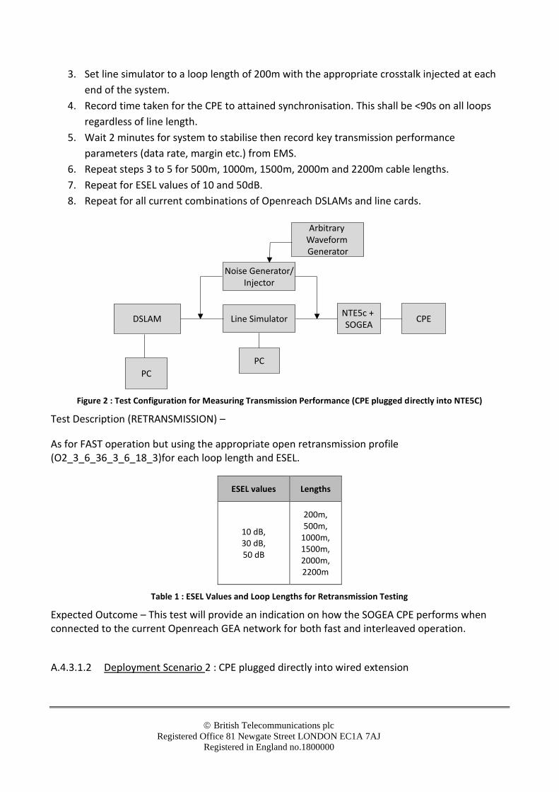
2. Connect CPE to DSLAM using the test setup shown in Figure 2.
© British Telecommunications plc
Registered Office 81 Newgate Street LONDON EC1A 7AJ
Registered in England no.1800000
3. Set line simulator to a loop length of 200m with the appropriate crosstalk injected at each
end of the system.
4. Record time taken for the CPE to attained synchronisation. This shall be <90s on all loops
regardless of line length.
5. Wait 2 minutes for system to stabilise then record key transmission performance
parameters (data rate, margin etc.) from EMS.
6. Repeat steps 3 to 5 for 500m, 1000m, 1500m, 2000m and 2200m cable lengths.
7. Repeat for ESEL values of 10 and 50dB.
8. Repeat for all current combinations of Openreach DSLAMs and line cards.
Figure 2 : Test Configuration for Measuring Transmission Performance (CPE plugged directly into NTE5C)
Test Description (RETRANSMISSION) –
As for FAST operation but using the appropriate open retransmission profile (O2_3_6_36_3_6_18_3)for each loop length and ESEL.
ESEL values Lengths
10 dB, 30 dB, 50 dB
200m, 500m,
1000m, 1500m, 2000m, 2200m
Table 1 : ESEL Values and Loop Lengths for Retransmission Testing
Expected Outcome – This test will provide an indication on how the SOGEA CPE performs when connected to the current Openreach GEA network for both fast and interleaved operation.
A.4.3.1.2 Deployment Scenario 2 : CPE plugged directly into wired extension
DSLAM
PC
Line Simulator
PC
Noise Generator/Injector
NTE5c + SOGEA
CPE
Arbitrary Waveform Generator
© British Telecommunications plc
Registered Office 81 Newgate Street LONDON EC1A 7AJ
Registered in England no.1800000
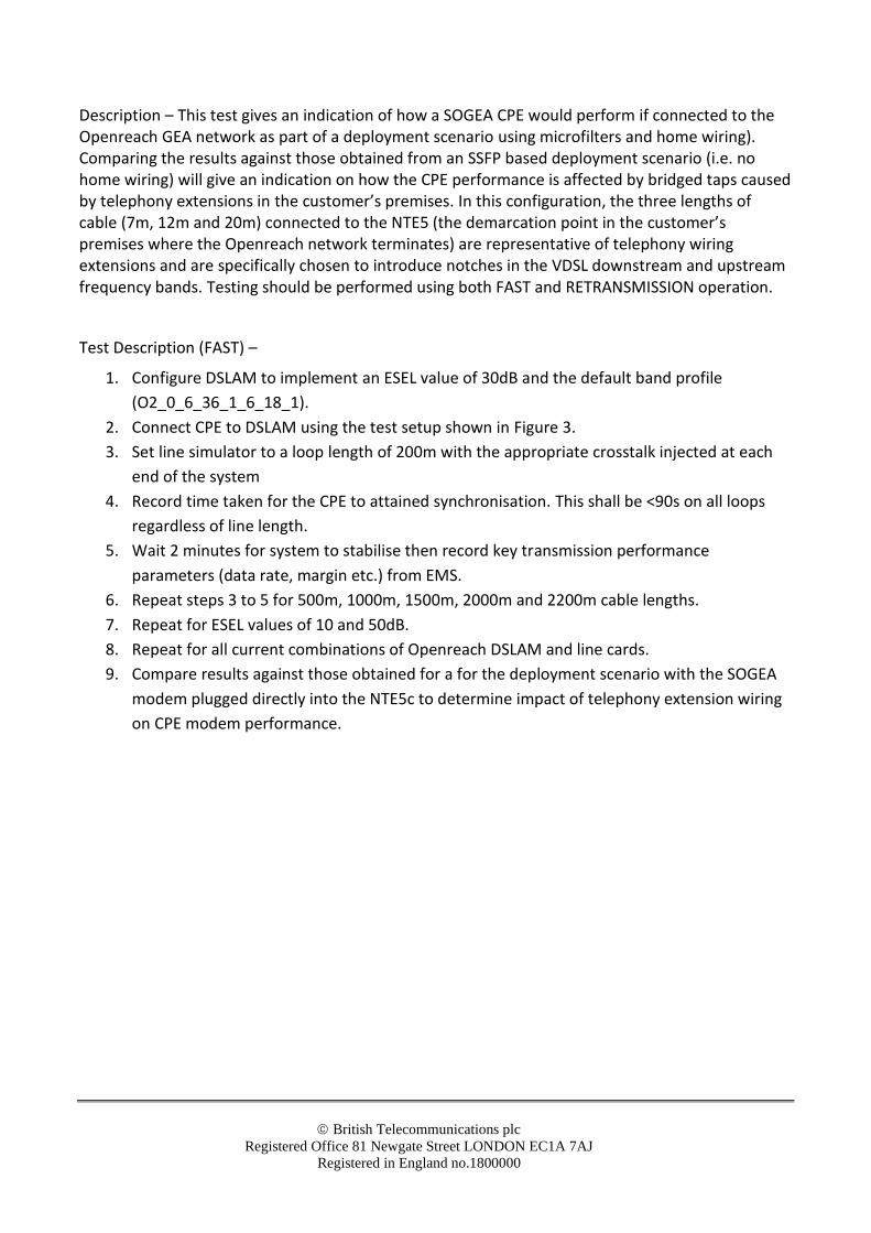
Description – This test gives an indication of how a SOGEA CPE would perform if connected to the Openreach GEA network as part of a deployment scenario using microfilters and home wiring). Comparing the results against those obtained from an SSFP based deployment scenario (i.e. no home wiring) will give an indication on how the CPE performance is affected by bridged taps caused by telephony extensions in the customer’s premises. In this configuration, the three lengths of cable (7m, 12m and 20m) connected to the NTE5 (the demarcation point in the customer’s premises where the Openreach network terminates) are representative of telephony wiring extensions and are specifically chosen to introduce notches in the VDSL downstream and upstream frequency bands. Testing should be performed using both FAST and RETRANSMISSION operation.
Test Description (FAST) –
1. Configure DSLAM to implement an ESEL value of 30dB and the default band profile
(O2_0_6_36_1_6_18_1).
2. Connect CPE to DSLAM using the test setup shown in Figure 3.
3. Set line simulator to a loop length of 200m with the appropriate crosstalk injected at each
end of the system
4. Record time taken for the CPE to attained synchronisation. This shall be <90s on all loops
regardless of line length.
5. Wait 2 minutes for system to stabilise then record key transmission performance
parameters (data rate, margin etc.) from EMS.
6. Repeat steps 3 to 5 for 500m, 1000m, 1500m, 2000m and 2200m cable lengths.
7. Repeat for ESEL values of 10 and 50dB.
8. Repeat for all current combinations of Openreach DSLAM and line cards.
9. Compare results against those obtained for a for the deployment scenario with the SOGEA
modem plugged directly into the NTE5c to determine impact of telephony extension wiring
on CPE modem performance.

© British Telecommunications plc
Registered Office 81 Newgate Street LONDON EC1A 7AJ
Registered in England no.1800000
Figure 3 : Test Configuration for Measuring Transmission Performance (CPE plugged directly into wired extension)
Test Description (RETRANSMISSION) –
As for FAST operation but using the open retransmission profile O2_3_6_36_3_6_18_3.
Expected Outcome – This test will provide an indication on how the SOGEA CPE performs when connected to the current Openreach GEA network for both fast and retransmission operation.
A.4.3.2 Verification of ‘Router Only’ Functionality
Requirements as defined in SIN498.
Annex B Test Requirements for SOGEA Over ADSL2
Not Applicable for SOGEA
Annex C Test Requirements for SOGEA Over G.fast (SOGfast)
This Annex provides a detailed breakdown of the modem conformance tests (MCT) requirements to enable a piece of vendor CPE to be validated against the CPE Requirements defined in Section 5 of this document. This is largely based on the requirements of SIN527 [4] with any specific requirements for SOGfast shown in the relevant sub-sections.
DSLAM
PC
Line Simulator
PC
Noise Generator/Injector
NTE5c +SOGEA
CPE
12m
20m
7m
Internal wiring (e.g. CW1308)
uF
uF
uF
uF Micro-filter + extension socket
Arbitrary Waveform Generator

© British Telecommunications plc
Registered Office 81 Newgate Street LONDON EC1A 7AJ
Registered in England no.1800000
C.1 Test Configuration
Requirements as defined in SIN527.
All physical layer tests should be performed with the CPE modem connected to a SOGfast isolating faceplate fitted to an NTE5C unless otherwise stated.
C.1.1 Band Profile
Requirements as defined in SIN527.
C.1.2 Loops
Requirements as defined in SIN527.
C.1.3 Plain Old Telephony Service (POTS)
Not Required for SOGfast
C.1.4 Crosstalk
Requirements as defined in SIN527.
C.2 Network Equipment
Requirements as defined in SIN527.
C.3 Test Equipment
Requirements as defined in SIN257.
C.3.1 Details of Impedance Matching Network
Requirement as defined in SIN 527.
C.4 Modem Conformance test (MCT) Requirements for SOGfast
Requirements as defined in SIN527.
C.4.1 Initial Gating Tests
Requirements as defined in SIN527.
C.4.1.1 Synchronisation
© British Telecommunications plc
Registered Office 81 Newgate Street LONDON EC1A 7AJ
Registered in England no.1800000
Requirements as defined in SIN527.
C.4.1.2 Network Interference
Requirements as defined in SIN527
C.4.2 Modem Conformance Tests
See Section 5 for details of the specific requirements to which these conformance tests refer.
C.4.2.1 Physical Layer Tests
Each of the following Sections defines the test required to demonstrate compliance to a particular requirement of SIN517. The requirement number is shown in brackets after the title of the test.
C.4.2.2 Physical Connection (R.PHY.1)
Requirements as defined in SIN527.
C.4.2.3 G.fast Layer
C.4.2.3.1 Support of Mandatory Requirements of G.9700 and G.9701 (R.FAST.1)
Requirements as defined in SIN527.
C.4.2.3.2 Support of Profile 106a and Profile 106b (R.FAST.3)
Requirements as defined in SIN527.
C.4.2.3.3 Compliance with BT ANFP Part F (R.FAST.4)
Requirements as defined in SIN527.
C.4.2.3.4 Support of Cabinet Based Cabinet Based G.fast Operation (R.FAST.5)
Requirements as defined in SIN527.
C.4.2.3.5 Support of UPBO (R.FAST.4 and R.FAST.25)
Requirements as defined in SIN527.
C.4.2.3.6 Support of Spectral Compatibility with VDSL2 services (R.FAST.6)
Requirements as defined in SIN527.
C.4.2.3.7 Support of Seamless Rate Adaption (R.FAST.10)
Requirements as defined in SIN527.

© British Telecommunications plc
Registered Office 81 Newgate Street LONDON EC1A 7AJ
Registered in England no.1800000
C.4.2.3.8 Support of Downstream and Upstream Retransmission (R.FAST.8)
Requirements as defined in SIN527.
C.4.2.3.9 Support of Vectoring (R.FAST.9)
Requirements as defined in SIN527.
C.4.2.3.10 Support of Fast Rate Adaption (R.FAST.11)
Requirements as defined in SIN527.
C.4.2.3.11 Support of Bit Swap (R.FAST.27)
Requirements as defined in SIN527.
C.4.2.3.12 Correct reporting of Vendor Information (R.FAST.21)
Requirements as defined in SIN527.
C.4.2.3.13 Support of RFI and IAR notching (R.FAST.24)
Requirements as defined in SIN527.
C.4.2.3.14 Verification of Hlog and QLN
Requirements as defined in SIN527.
C.4.2.4 Ethernet Layer
C.4.2.4.1 Ethernet Frame Size (R.ETH.1)
Requirements as defined in SIN527.
C.4.2.5 WAN/VLAN Layer
C.4.2.5.1 Ingress Frames Encapsulated Within IEEE.802.1Q VLAN (R.WAN.2)
Requirements as defined in SIN527.
C.4.2.5.2 Simultaneous Support of Multicast and Unicast over the same VLAN (R.WAN.3)
Requirements as defined in SIN527.
C.4.2.5.3 Ethertype Field of Ethernet Frame Set to 0x8100 on Ingress to Openreach UNI (R.WAN.4)
Requirements as defined in SIN527.
C.4.2.5.4 CVLAN Canonical Format Indicator Set to 0 on Ingress to Openreach UNI (R.WAN.5)
Requirements as defined in SIN527.
C.4.2.5.5 VLAN ID Set to 101 (R.WAN.6)
Requirements as defined in SIN527.
C.4.2.5.6 IGMP Reports Encoded Correctly (R.WAN.7)
© British Telecommunications plc
Registered Office 81 Newgate Street LONDON EC1A 7AJ
Registered in England no.1800000
Requirements as defined in SIN527.
C.4.2.5.7 Multicast Frames Detected and Processed Correctly (R.WAN.8)
Requirements as defined in SIN527.
C.4.2.6 OAM Layer
C.4.2.6.1 Support of ‘Dying Gasp’ (R.OAM.1)
Requirements as defined in SIN527.
C.4.2.6.2 Support of ‘Passive Mode’ (R.OAM.2)
Requirements as defined in SIN527.
C.4.2.6.3 Support of 802.3AH Loopback (R.OAM.3)
Requirements as defined in SIN527.
C.4.2.6.4 Support of Loop Back Messages (R.OAM.8)
Requirements as defined in SIN527.
C.4.2.7 CPE Filters
R.FILTER.1 Centralised Splitters
Not Applicable to SOGfast
R.FILTER.2 Distributed Splitters (i.e. micro-filters)
Not Applicable to SOGfast
-END-