November 2017, Volume 4, Issue 11 JETIR (ISSN 2349 5162 ...
10
November 2017, Volume 4, Issue 11 JETIR (ISSN-2349-5162) JETIR1711065 Journal of Emerging Technologies and Innovative Research (JETIR) www.jetir.org 344 FIVE-LEG AC-DC-AC CONVERTER-FED INDUCTION MOTOR DRIVE BASED ON ANFIS CONTROLLER G.venkatapathi 1 , S.Sridhar 2 1 M.Tech student, Electrical Engineering, JNTUA College ofEngineering, Anantapuramu, India. 2 Asst.professor, Electrical Engineering at JNTUA College of Engineering, Anantapuramu, India. Abstract—AC-DC-AC converter-fed induction motor drive is for the most part acknowledged by back-to-back three-phase converters. Be that as it may, fault in a single semiconductor switch will make it inoperative. To empower proceeded with controllable operation if there should arise an occurrence of the issues happening in the converter, the five-leg converter with a shared leg between the grid and load sides is a conceivable arrangement. Be that as it may, this topology represents an inherent two-objective control issue since its grid and load sides ought to be controlled all the while. In this paper, new control scheme in view of the FCS-MPC combined with intrinsic characteristics for the five-leg converter is existed for autonomous control of the rectifier and inverter subsystem with the shared leg over current imperative. Another novel ANFIS control is proposed in this paper and with a specific end goal to give a total assessment of the proposed ANFIS control scheme, the traditional MPC control plot is directed for comparison. Simulation results about are given to approve the adequacy of the proposed scheme. I. INTRODUCTION THE induction motor (IM) has turned out to be one of the primary actuators for modern applications on account of its cost,reliability,roughness,straightforwardness,productivity,and simplicity of fabricate. The back-to-back three-phase converters help to accomplish superior from an IM [1], particularly in the high- control regenerative drives. In any case, this converter is delicate to control switch fault. In AC-DC-AC converters, these disappointments can happen at the frontend rectifier or at the output inverter. To enhance the reliability quality of the IM drives, fault tolerant plans for AC-DC-AC converter must be actualized. One of the option plans is to include equipment repetition into the systems. Be that as it may, it is a costive, weight and space devouring arrangement [2]. In this way, another healing arrangements actualized by real time fault identification and converter reconfiguration has a steady improvement amid the previous decade, known as nonredundant fault tolerant structures. On account of the nonredundant fault working structures, the converter can be produced either with a DC-bus midpoint association[3] or with a common leg imparted to another motor drive [4] or rectifier [5] to supply the motor drive. The DC-bus mid- point association strategy will definitely cause the capacitor voltage variance and additional endeavors must be paid to adjust for this change, while the shared leg case, this issue is kept away from. With shared-leg topology, the disappointment of one leg in the input rectifier or one leg in the inverter can be viably overseen. As an outcome, a few papers in view of pulse width modulation (PWM) procedures were distributed [5]. A PWM procedure for applications in which the loadfrequency was equivalent to the gridfrequency (e.g., UPS applications) was proposed to accomplish conceivable control of this topology. Be that as it may, this technique lost the value of variable frequency in inverter since the gridfrequency was constantly steady. Two leg-to-leg rather than three leg-toneutral regulated voltages were proposed in [5] to control the rectifier/inverter autonomously. Be that as it may, since some leg-to-leg regulation examples had no comparable leg-to- impartial exchanging designs in the five leg converter, the estimated calculation received in choosing exchanging examples would prompt a ton of current ripples. The high common modevoltage which prompted current symphonious misfortunes was appeared. All the more imperatively, the possibly overcurrent in the common leg was not considered in these papers. As a conceivable arrangement, a model prescient control plot for the synchronous control of the rectifier and inverter is considered in this paper. Limited control-set model prescient control (FCS-MPC) was as of late proposed as a successful plan in superior control of the power converters, for example, factor speed engine drives [6], grid converter,back-back converter and other power electronic converter setup. No paper to the best of creators' input has any past endeavor to use FCS-MPC in conjunction with a five-leg AC-DC-AC converter-sustained acceptance engine. In this paper, the model of the five-leg AC-DC-AC converter is broke down, and a control scheme in view of FCS- MPC is proposed for elite control of a five-leg converter-nourished induction motor. Indeed, with an extremely adaptable structure of cost work in FCS-MPC, it is conceivable to include the limitation (e.g., shared-leg overcurrent) and other control targets. A FCS-MPC with bring down figuring load created from the innate normal for the five-leg converter is proposed for pragmatic usage. Fig.1. AC-DC-AC converter-fed motor drive with reconfiguration The voltage restriction of the fiveleg AC-DC-AC converter is examined and the speeds extend for free control of the rectifier and motor is given. II. MODELING OF THE FIVE-LEG AC-DC-AC DRIVE Without loss of simplification, it is accepted that all through the paper, when the switch faults happen in the phase l3 of the inverter, the comparing motorphase that lost the supply is associated with the leg g3 of the rectifier for faulttolerant operation, as appeared in Fig.1. In five-leg AC-DC-AC drive framework
Transcript of November 2017, Volume 4, Issue 11 JETIR (ISSN 2349 5162 ...

November 2017, Volume 4, Issue 11 JETIR (ISSN-2349-5162)
JETIR1711065 Journal of Emerging Technologies and Innovative Research (JETIR) www.jetir.org 344
FIVE-LEG AC-DC-AC CONVERTER-FED INDUCTION
MOTOR DRIVE BASED ON ANFIS CONTROLLER
G.venkatapathi1, S.Sridhar
2
1M.Tech student, Electrical Engineering, JNTUA College ofEngineering, Anantapuramu, India.
2Asst.professor, Electrical Engineering at JNTUA College of Engineering, Anantapuramu, India.
Abstract—AC-DC-AC converter-fed induction motor drive is for
the most part acknowledged by back-to-back three-phase
converters. Be that as it may, fault in a single semiconductor
switch will make it inoperative. To empower proceeded with
controllable operation if there should arise an occurrence of the
issues happening in the converter, the five-leg converter with a
shared leg between the grid and load sides is a conceivable
arrangement. Be that as it may, this topology represents an
inherent two-objective control issue since its grid and load sides
ought to be controlled all the while. In this paper, new control
scheme in view of the FCS-MPC combined with intrinsic
characteristics for the five-leg converter is existed for autonomous
control of the rectifier and inverter subsystem with the shared leg
over current imperative. Another novel ANFIS control is
proposed in this paper and with a specific end goal to give a total
assessment of the proposed ANFIS control scheme, the traditional
MPC control plot is directed for comparison. Simulation results
about are given to approve the adequacy of the proposed scheme.
I. INTRODUCTION
THE induction motor (IM) has turned out to be one of the
primary actuators for modern applications on account of its
cost,reliability,roughness,straightforwardness,productivity,and
simplicity of fabricate. The back-to-back three-phase converters
help to accomplish superior from an IM [1], particularly in the high-
control regenerative drives. In any case, this converter is delicate to
control switch fault. In AC-DC-AC converters, these
disappointments can happen at the frontend rectifier or at the output
inverter. To enhance the reliability quality of the IM drives, fault
tolerant plans for AC-DC-AC converter must be actualized. One of
the option plans is to include equipment repetition into the systems.
Be that as it may, it is a costive, weight and space devouring
arrangement [2]. In this way, another healing arrangements
actualized by real time fault identification and converter
reconfiguration has a steady improvement amid the previous
decade, known as nonredundant fault tolerant structures.
On account of the nonredundant fault working structures,
the converter can be produced either with a DC-bus midpoint
association[3] or with a common leg imparted to another motor
drive [4] or rectifier [5] to supply the motor drive. The DC-bus mid-
point association strategy will definitely cause the capacitor voltage
variance and additional endeavors must be paid to adjust for this
change, while the shared leg case, this issue is kept away from.
With shared-leg topology, the disappointment of one leg in the
input rectifier or one leg in the inverter can be viably overseen. As
an outcome, a few papers in view of pulse width modulation
(PWM) procedures were distributed [5]. A PWM procedure for
applications in which the loadfrequency was equivalent to the
gridfrequency (e.g., UPS applications) was proposed to accomplish
conceivable control of this topology. Be that as it may, this
technique lost the value of variable frequency in inverter since the
gridfrequency was constantly steady. Two leg-to-leg rather than
three leg-toneutral regulated voltages were proposed in [5] to
control the rectifier/inverter autonomously. Be that as it may, since
some leg-to-leg regulation examples had no comparable leg-to-
impartial exchanging designs in the five leg converter, the estimated
calculation received in choosing exchanging examples would
prompt a ton of current ripples. The high common modevoltage
which prompted current symphonious misfortunes was appeared.
All the more imperatively, the possibly overcurrent in the common
leg was not considered in these papers. As a conceivable
arrangement, a model prescient control plot for the synchronous
control of the rectifier and inverter is considered in this paper.
Limited control-set model prescient control (FCS-MPC) was as of
late proposed as a successful plan in superior control of the power
converters, for example, factor speed engine drives [6], grid
converter,back-back converter and other power electronic converter
setup. No paper to the best of creators' input has any past endeavor
to use FCS-MPC in conjunction with a five-leg AC-DC-AC
converter-sustained acceptance engine.
In this paper, the model of the five-leg AC-DC-AC
converter is broke down, and a control scheme in view of FCS-
MPC is proposed for elite control of a five-leg converter-nourished
induction motor. Indeed, with an extremely adaptable structure of
cost work in FCS-MPC, it is conceivable to include the limitation
(e.g., shared-leg overcurrent) and other control targets. A FCS-MPC
with bring down figuring load created from the innate normal for
the five-leg converter is proposed for pragmatic usage.
Fig.1. AC-DC-AC converter-fed motor drive with reconfiguration
The voltage restriction of the fiveleg AC-DC-AC converter is
examined and the speeds extend for free control of the rectifier and
motor is given.
II. MODELING OF THE FIVE-LEG AC-DC-AC DRIVE
Without loss of simplification, it is accepted that all
through the paper, when the switch faults happen in the phase l3 of
the inverter, the comparing motorphase that lost the supply is
associated with the leg g3 of the rectifier for faulttolerant operation,
as appeared in Fig.1. In five-leg AC-DC-AC drive framework

November 2017, Volume 4, Issue 11 JETIR (ISSN-2349-5162)
JETIR1711065 Journal of Emerging Technologies and Innovative Research (JETIR) www.jetir.org 345
considered in this paper (Fig.1), one side of the converter is
associated with a three-phase adjusted sinusoidal source, and the
opposite side of the converter is associated with a three-phase
acceptance machine. The leg g3 is shared by the two sides.
Keeping in mind the end goal to determine the proposed
control plot, the five-leg back-back converter is considered as a
three-phase dynamic front-end rectifier and a three-phase inverter.
The dynamic frontend rectifier essentially works as a boost chopper
(frequently called a boost rectifier) with AC voltage at the input,
however dc voltage at the output, keeping up sinusoidal line
current. The threephase inverter gets dc voltage and proselytes it to
ac voltage for the engine drive. The point by point model of each
part will be explained in the accompanying content.
A. Five-Leg Converter Model
In this paper, the converter is considered for execution by
perfect switches (i.e., with no dead time and no voltage drop).
Subsequently, exchanging conditions of any converter legs can be
composed as takes after:
{
( ) (1)
B. Three-Phase Active Front-End Rectifier Model
The continuous-time model of a three-phase active front-
endrectifier can be expressed by the following equation: ( )
( )
( )
( ) (2)
Where is the input current vector, is the grid
voltage vector, is thevoltage vector generated by the
active front-end rectifier, is the equivalent series resistance, is
the filter inductance.The predicted grid current is calculated by the
following discrete-time equation
( ) (
) ( )
( )
( )
(3)
Which is obtained from the discretizing (2) for a sampling timeTs .
Since the control variables of the rectifier is the activeand reactive
power.
Considering the input voltage and current vectors in
orthogonalcoordinates, the predicted instantaneous input active
andreactive power are given with
( ) { ( ) ( )} (4)
( ) { ( ) ( )} (5)
For a high sampling frequency in this paper, with regard tothe grid
fundamental frequency, it can be assumed that ( ) ( ).
C. Induction Motor Model
The dynamic model of an induction motor viewing
fromthe stator reference frame can be given as follows:
(6)
(7)
(8)
(9)
(10)
Where and ( ) refer to shared and stator (rotor)inductance,
while ( ) represent the stator (rotor) current, ( ) and
( )denote stator (rotor) resistance and stator(rotor) flux, and
denote torque and number of the pole pairs, and represent the
stator voltage and rotor electrical speed. Since the measured
variables are stator currents and rotor speed, all the other quantities
are either estimated or predicted. As the stator flux is not
measurable, stator flux isestimated from rotor flux by substituting in (9) to (8)
(11)
Wherethe denote the leakage factor. The can be obtainedby
substituting in (6) to (8)
(12)
Where ⁄ is the rotor time constant. Since the
controlvariable of the induction motor drive is stator flux and
torque,these values should be predicted at sampling time instant
k+1.The stator flux can be predicted by discretizing (7)
( ) ( ) ( ) ( ) (13)
The torque can be predicted by
( )
{ ( )
( )} (14)
Where the predicted stator current can be obtained fromequation
(6)-(9)
( ) (
) ( )
{
((
( ) ) ( )
( ))} (15)
Where ⁄ is the rotor coupling factor, refers to the equivalent resistance, denotes the
equivalent time constant.
Fig.2. Control block diagram of the FCS-MPC
III. FCS-MPC CONTROL SCHEME
In FCS-MPC, the control goals are characterized as the
cost work, making the FCS-MPC plot with a superb capacity to
manage the multi-input multi-output (MIMO) framework. It can
treat the five-leg AC-DC-AC converter as one
system. The inward circles of rectifier and inverter
subsystems are controlled by one cost work. The order dc link
voltage is contrasted and the genuine and the mistake motion
through a PI controller is used to create the dynamic power charge
while the summon speed is contrasted and the real also, the

November 2017, Volume 4, Issue 11 JETIR (ISSN-2349-5162)
JETIR1711065 Journal of Emerging Technologies and Innovative Research (JETIR) www.jetir.org 346
mistake motion through a PI controller is used to create the torque
summon. The entire control square of the proposed scheme is given
in Fig. 2. In standard FCS-MPC, all attainable inputvoltage vectors
comparing to the conceivable exchanging states are assessed, and
the one with the most reduced cost work esteem will be connected
in the following testing time frame. Be that as it may, a five-leg
converter has 32 exchanging states. An entire assessment of the
standard FCS-MPC requires 32 sets variable forecast and cost work
advancement. With the substantial calculation trouble, the testing
frequency is constrained, which prompt huge output current
willripple.
To take care of this problem, a FCS-MPC with bring down
computational weight must be actualized. At long last, by assessing
the cost capacities at two differentcommon leg expresses, the ideal
exchanging condition of the five-leg converter framework can be
resolved.
A. Cost Function Design
As per the switching condition of the shared leg, the cost
elements of the rectifier and the inverter should be figured twice.
Every assessment requires 8 sets variable forecast and cost work
streamlining (four sets for rectifier and four sets for inverter). Along
these lines, with regards to the dynamic front-end rectifier
subsystem, the cost work, intended to control the dynamic and
receptive power, can be given by
| ( ) |
| ( ) |
(16)
* +
Where and are, separately, the future references of dynamic
power and receptive power at skyline k+1, PN is the greatest output
energy of the rectifier. With regards to the enlistment engine drive
subsystem, the cost work, intended to control the stator motion and
torque, can be given by
| ( ) |
|| | | ( )| |
| | (17)
* + Where is a measuring factor which finds the relative significance
of the torque and stator motion, and |
|are the future references
of torque, and transition at skyline k+1, separately. and| → |are
the greatness of the appraised torque and stator motion. The factor
can be set to 1 if the relative significance of torque and motion is
the same [7]. Since the voltage vectors of the two subsystems are
free to each other, the cost capacity of the entire framework can be
given as takes after
( ) (18)
Where J0 is the ideal cost work on account of sharedleg condition
of 0, while J1 is the ideal cost work on account of the common leg
condition of 1. is a measuring factor which speaks to the relative
significance of the rectifier and the inverter, and subscript 0/1
demonstrates switch condition of the common leg. Regularly, the
measuring factor is set to
(19)
The last ideal changing blend connected to the fiveleg converter can
be created by assessing the cost work J0 and J1 .The flowchart of
the plan is given in Fig.3. SG,iand SL,i * + shows exchanging
condition of the sharedleg) are the ideal changing states expected to
be connected to the rectifier and inverter.
B. Condition for Independent Control
In five-leg AC-DC-AC converter, the principal input
voltage and output voltage can be controlled freely, given that the
estimation of the dc-link voltage is satisfactory. Be that as it may, as
one leg of the inverter imparted to the rectifier, exchanging systems
must give sinusoidal voltage to both inverter and rectifier at the
shared leg. In a fault tolerant system, the most vital issue is to
accomplish a steady and worthy (likely corrupted) execution. On
the off chance that the dc-link voltage is not expanded, the
restriction of voltage will bring about the corrupted speed
customizable range. The most extreme customizable speed is
indicated as takes after.
On account of FCS-MPC, just a single real voltage vector
is connected in an exchanging period. Finding the momentary
voltage from the reference voltage is unimaginable. Thus, the
crucial voltages are approximated. On account of the rectifier, the
major voltage with receptive power controlled can be approximated
by the virtual motion (VF).
∫ (20)
When all is said in done, the parasitic wonders and quantization
mistake prompt disparity between the recreated voltages and the
acknowledged voltages. The basic of this blunder may prompt
wrong outcomes. In this manner, low pass channel (LPF) is used to
dispense with this blunder. The high pass channel (HPF) is utilized
to make up for the phase move and plentifulness constriction of the
LPF. The exchange capacity can be given as
( )
( ) (21)
Where k1 and k2 are the cutoff frequency of LPF and HPF,
individually. Consequently, the essential input voltage can be given
a
(22)
On account of the inverter, the basic output voltage can be given as
(23)
As the frequency of the inputvoltage is settled, at that point
adequacy of the essential input voltage is settled. Along these lines,
the biggest amplitude of output voltage for inverter can be given as
takes after
(24)
Where Vmax = √ is the biggest sufficiency of dc-link voltage
accessible, Vgm and Vlm is the biggest amplitude of dc-connect
voltage accessible for rectifier and inverter, separately. Join with
(23), the greatest speed movable range for freely control of the five-
leg AC-DC-AC converter-encouraged engine drive can be indicated
as takes after.
| | (25)
Where is the speed confinement for free control of the
converter.
C. Overcurrent Constraint
During a few transients, the five-leg converter streams can
be impressively high, particularly in the shared leg, which would
harm the converter. It is alluring to confine these streams in the
five-leg converter. In the traditional technique, the overcurrent
security is accomplished by limiting the network and load current
independently (i.e., the current of each side is compelled to half of
the permitted converter current). For this situation, the output
current ability is restricted. If there should be an occurrence of the
FCS-MPC plot, this inquiry can be stayed away from. This can be
executed by including an extra nonlinear term in the cost work. This
nonlinear term produces a high esteem when the streams surpass as
far as possible and equivalent to zero when the ebbs and flows

November 2017, Volume 4, Issue 11 JETIR (ISSN-2349-5162)
JETIR1711065 Journal of Emerging Technologies and Innovative Research (JETIR) www.jetir.org 347
inside the cutoff points. Along these lines, the cost work (16)(17)
can be revamped as
| ( ) |
| ( ) |
(| ( )| )
(26)
| ( ) |
|| | | ( )| |
| | (| ( )|
) (27)
Where is a high esteem and f (.) is a legitimate capacity, when
the condition is valid, the estimation of the capacity is 1, while the
condition is false, the estimation of the capacity is 0. The
anticipated transient current of the shared leg can be given
( ) ( ) ( ) (28)
In a drive framework, the execution of the inverter offers need to
rectifier framework. In this manner, with regards to the shared leg
current imperative, it ought to be added to the rectifier cost work
| ( ) |
| ( ) |
[ (| ( )| )
(| ( )| )]
(29)
IV.CONVENTIONAL PWM CONTROL SCHEME
Keeping in mind the end goal to give a total assessment of
the proposed control plot, the customary PWM scheme is led for
correlation. The acknowledgment of PWM control scheme depends
on the voltage-arranged control (VOC) plot for the rectifier and
field-situated control (FOC) scheme for the engine with PWM
procedure. Among the few PWM approaches examined in the
writing for five-leg approach, it appears that the proposed strategy
in [4] delivers less present sounds and gives full dc-bus usage. The
entire PWM scheme is delineated in Fig.4. For a reasonable
examination, the PWM control scheme is actualized with
decoupling term in the engine drive and rectifier to enhance the
elements. Keeping in mind the end goal to give the most ideal
control execution, the PI current controller is tuned legitimately to
give the most ideal control execution and the output of the PI
controllers is tweaked utilizing PWM to shape the five-leg
exchanging states.
V. AN ADAPTIVE NEURO-FUZZY INFERENCE SYSTEM
A adaptive neuro-fuzzy derivation framework or versatile
system based fuzzy deduction framework (ANFIS) is a sort of
counterfeit neural system that depends on Takagi–Sugeno fuzzy
induction framework. The strategy was produced in the mid 1990s.
Since it coordinates both neural systems and fuzzy rationale
standards, it can possibly catch the advantages of both in a solitary
structure. Its induction framework compares to an arrangement of
fuzzy IF–THEN decides that have learning capacity to inexact
nonlinear capacities. Thus, ANFIS is thought to be an all inclusive
estimator. For utilizing the ANFIS as a part of a more productive
and ideal way, one can utilize the best parameters acquired by
hereditary calculation. ANFIS: Artificial Neuro-Fuzzy Inference
Systems
ANFIS are a class of adaptive networks that are functionally
equivalent to fuzzy inference systems.
ANFIS represent Sugeno e Tsukamoto fuzzy models.
ANFIS uses a hybrid learning algorithm.
In the field of artificial intelligence neuro-fuzzy alludes to mixes of
fake neural systems and fuzzy rationale. Neuro-fuzzy hybridization
brings about a half and half astute framework that synergizes these
two procedures by joining the human-like thinking style of fuzzy
frameworks with the learning and connectionist structure of neural
systems. Neuro-fuzzy hybridization is generally named as Fuzzy
Neural Network (FNN) or Neuro-Fuzzy System (NFS) in the
writing. Neuro-fuzzy framework (the more mainstream term is
utilized from this time forward) fuses the human-like thinking style
of fuzzy frameworks using fuzzy sets and a semantic model
comprising of an arrangement of IF-THEN fuzzy standards. The
primary quality of neuro-fuzzy frameworks is that they are
widespread approximates with the capacity to request interpretable
IF-THEN principles.
The quality of neuro-fuzzy frameworks includes two conflicting
necessities in fuzzy displaying: interpretability versus exactness.
Practically speaking, one of the two properties wins. The neuro-
fuzzy in fuzzy demonstrating research field is separated into two
zones: semantic fuzzy displaying that is centered on interpretability,
for the most part the Mamdani model; and exact fuzzy
demonstrating that is centered around exactness, primarily the
Takagi-Sugeno-Kang (TSK) model.
Albeit by and large thought to be the acknowledgment of a fuzzy
framework through connectionist arranges, this term is additionally
used to depict some different designs including: Deriving fuzzy
rules from trained RBF networks.
Representing fuzzification, fuzzy inference
and defuzzification through multi-layers feed-
forward connectionist networks.
It must be pointed out that interpretability of the Mamdani-type
neuro-fuzzy systems can be lost. To improve the interpretability of
neuro-fuzzy systems, certain measures must be taken, wherein
important aspects of interpretability of neuro-fuzzy systems are also
discussed.
A recent research line addresses the data stream mining case, where
neuro-fuzzy systems are sequentially updated with new incoming
samples on demand and on-the-fly. Thereby, system updates do not
only include a recursive adaptation of model parameters, but also a
dynamic evolution and pruning of model in order to handle concept
drift and dynamically changing system behavior adequately and to
keep the systems/models "up-to-date" anytime.
VI. SIMULATION RESULTS
(a)
Fig.3 Simulation results showing the shared-leg current: (a) with
theproposed shared-leg overcurrent constraint.
(a)
0 0.02 0.04 0.06 0.08 0.1 0.12 0.14 0.16 0.18 0.2-20
-10
0
10
20
Time(s)
Igshare
(A)
0 0.02 0.04 0.06 0.08 0.1 0.12 0.14 0.16 0.18 0.2-150
-100
-50
0
50
100
150
Time(s)
Vl3
(V)

November 2017, Volume 4, Issue 11 JETIR (ISSN-2349-5162)
JETIR1711065 Journal of Emerging Technologies and Innovative Research (JETIR) www.jetir.org 348
(b)
(c)
Fig.4 Simulation results showing (a) estimated phase l3 output
voltage(b) estimated phase g3 input voltage (c) estimated shared-leg
voltage.
Using Conventional PWM Scheme:
(a)
(b)
(c)
Fig.5. Simulation results showing the steady performance of the
fivelegAC-DC-AC scheme: (a)-(c) with the conventional PWM
scheme. Traces show [(a)] dc-link voltage, [(b)]active and reactive
power, [(c)] phase g1 voltage and current.
(a)
(b)
(c)
Fig.6 Simulation results showing the steady performance of the
fivelegAC-DC-AC scheme: (a)-(c) with the conventional PWM
scheme. Traces show [(a)] speed, [(b)] torque, [(c)] three-phase load
current.
Ig1conv
Fig. 7. Simulation results showing the steady performance of the
fiveleg converter.
AC-DC-AC scheme: (a),(b) with the conventional PWM scheme.
Traces show [(a)] grid phase g1 current, [(b)] spectrum of the grid
phase g1 current
Il1conv
Fig. 8. Simulation results showing the steady performance of the
fiveleg
AC-DC-AC scheme: (a),(b) with the conventional PWM scheme.
Traces show [(a)] motor phase l1 current,[(b)] spectrum of the
motor phase l1 current
Case 2a
(a)
(b)
0 0.02 0.04 0.06 0.08 0.1 0.12 0.14 0.16 0.18 0.2-150
-100
-50
0
50
100
150
Time(s)
Vg3(V
)
0 0.02 0.04 0.06 0.08 0.1 0.12 0.14 0.16 0.18 0.2-200
-100
0
100
200
Time(s)
Vgshare
(v)
0 0.02 0.04 0.06 0.08 0.1 0.12 0.14 0.16 0.18 0.20
100
200
300
400
500
Time(S)
Ud (
V)
0 0.02 0.04 0.06 0.08 0.1 0.12 0.14 0.16 0.18 0.2
0
200
400
600
800
Time(s)
P(w
),Q
(Var)
0 0.02 0.04 0.06 0.08 0.1 0.12 0.14 0.16 0.18 0.2-200
-150
-100
-50
0
50
100
150
200
Time(s)
eg
1(V
), Ig
1(A
)
0 0.02 0.04 0.06 0.08 0.1 0.12 0.14 0.16 0.18 0.20
100
200
300
400
500
600
Time(s)
W(r
pm
)
0 0.02 0.04 0.06 0.08 0.1 0.12 0.14 0.16 0.18 0.20
2
4
6
8
10
Time(s)
Te
(N-m
)
0 0.02 0.04 0.06 0.08 0.1 0.12 0.14 0.16 0.18 0.2-10
-5
0
5
10
Time(s)
Ila
bc(A
)
0 0.1 0.2 0.3 0.4 0.5 0.60
100
200
300
400
500
Time(s)
Ud
(V)
0.05 0.1 0.15 0.2 0.25 0.3 0.35 0.4 0.45 0.5 0.55-500
0
500
1000
1500
Time(s)
P(w
) Q
(va
r)

November 2017, Volume 4, Issue 11 JETIR (ISSN-2349-5162)
JETIR1711065 Journal of Emerging Technologies and Innovative Research (JETIR) www.jetir.org 349
(c)
Fig. 9. Simulation results showing the dynamic performance of the
fiveleg AC-DC-AC scheme during speed reversal maneuver: (a)-
(c)with the conventional PWM scheme. Traces show [(a)] dc-link
voltage, [(b)] active and reactive power, [(c)] phase g1 voltage and
current.
(a)
(b)
(c)
Fig. 10. Simulation results showing the dynamic performance of the
fiveleg AC-DC-AC scheme during speed reversal maneuver: (a)-(c)
with the conventional PWM scheme. Traces show [(a)] speed, [(b)]
torque, [(c)] three-phase current.
Case 2b
(a)
(b)
(c)
Fig. 11. Simulation results showing the dynamic performance of the
fiveleg AC-DC-AC scheme during load change: (a)-(c) with the
conventional PWM scheme. Traces show [(a)] dc-linkvoltage, [(b)]
active and reactive power, [(c)] phase g1 current.
(a)
(b)
(c)
Fig. 12. Simulation results showing the dynamic performance of the
fiveleg AC-DC-AC scheme during load change: (a)-(c) with the
conventional PWM scheme. Traces show [(a)] speed, [(b)] torque,
[(c)] three-phase current.
Using MPC controller Scheme:
(a)
(b)
0 0.1 0.2 0.3 0.4 0.5 0.6-200
-150
-100
-50
0
50
100
150
200
Time(s)
eg
1(V
), Ig
1(A
)
0 0.1 0.2 0.3 0.4 0.5 0.6-1000
-500
0
500
1000
Time(s)
w(r
pm
)
0 0.1 0.2 0.3 0.4 0.5 0.6-12
-10
-8
-6
-4
-2
0
2
4
6
Time(s)
Te
(N-m
)
0 0.1 0.2 0.3 0.4 0.5 0.6-4
-3
-2
-1
0
1
2
3
4
Time(s)
Ila
bc(A
)
0 0.1 0.2 0.3 0.4 0.5 0.6 0.7 0.8 0.9 10
100
200
300
400
500
Time(s)
w(r
pm
)
0 0.1 0.2 0.3 0.4 0.5 0.6 0.7 0.8 0.9 1
0
500
1000
1500
Time(s)
P(w
), Q
(Va
r)
0 0.1 0.2 0.3 0.4 0.5 0.6 0.7 0.8 0.9 1-10
-5
0
5
10
Time(s)
Ig1
(A)
0.1 0.2 0.3 0.4 0.5 0.6 0.7 0.8 0.9 10
200
400
600
800
1000
Time(s)
w(r
pm
)
0 0.1 0.2 0.3 0.4 0.5 0.6 0.7 0.8 0.9 1-15
-10
-5
0
5
10
15
Time(s)
Te
(N-m
)
0 0.1 0.2 0.3 0.4 0.5 0.6 0.7 0.8 0.9 1-10
-5
0
5
10
Time(s)
Ila
bc(A
)
0 0.02 0.04 0.06 0.08 0.1 0.12 0.14 0.16 0.18 0.20
100
200
300
400
500
Time(s)
Ud
(V)
0 0.02 0.04 0.06 0.08 0.1 0.12 0.14 0.16 0.18 0.2-100
0
100
200
300
400
500
600
700
800
Time(s)
P(w
),Q
(va
r)
November 2017, Volume 4, Issue 11 JETIR (ISSN-2349-5162)
JETIR1711065 Journal of Emerging Technologies and Innovative Research (JETIR) www.jetir.org 350
(c)
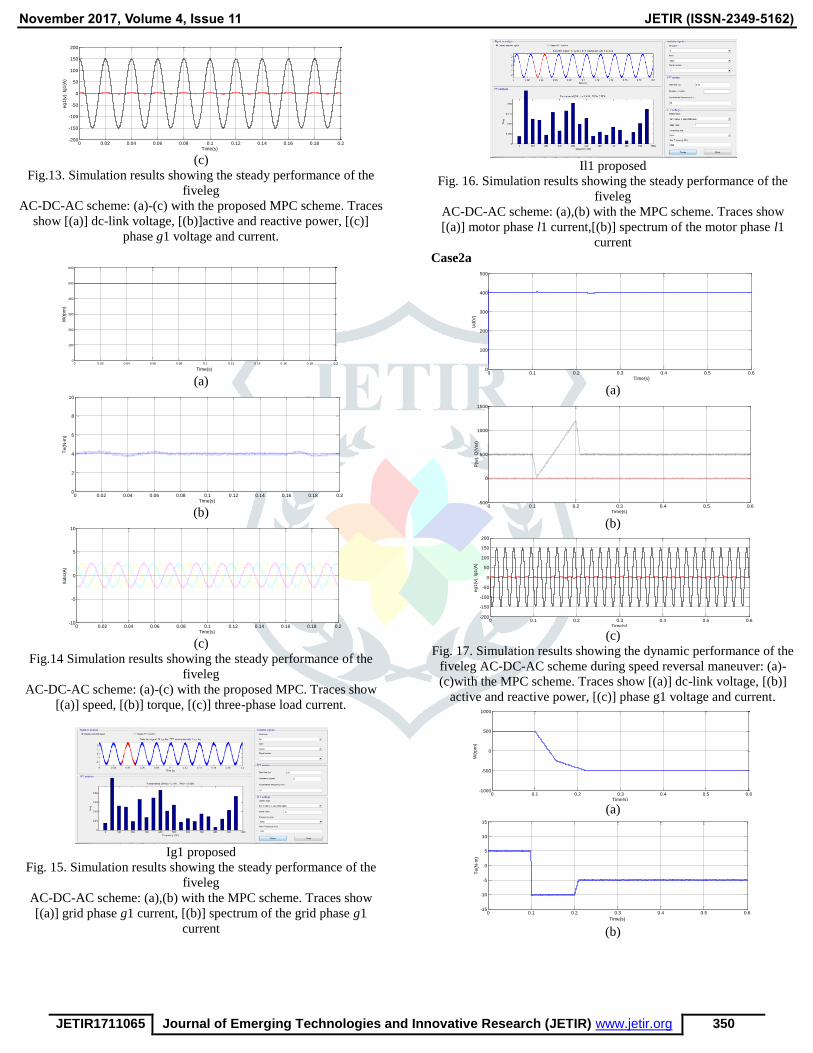
Fig.13. Simulation results showing the steady performance of the
fiveleg
AC-DC-AC scheme: (a)-(c) with the proposed MPC scheme. Traces
show [(a)] dc-link voltage, [(b)]active and reactive power, [(c)]
phase g1 voltage and current.
(a)
(b)
(c)
Fig.14 Simulation results showing the steady performance of the
fiveleg
AC-DC-AC scheme: (a)-(c) with the proposed MPC. Traces show
[(a)] speed, [(b)] torque, [(c)] three-phase load current.
Ig1 proposed
Fig. 15. Simulation results showing the steady performance of the
fiveleg
AC-DC-AC scheme: (a),(b) with the MPC scheme. Traces show
[(a)] grid phase g1 current, [(b)] spectrum of the grid phase g1
current
Il1 proposed
Fig. 16. Simulation results showing the steady performance of the
fiveleg
AC-DC-AC scheme: (a),(b) with the MPC scheme. Traces show
[(a)] motor phase l1 current,[(b)] spectrum of the motor phase l1
current
Case2a
(a)
(b)
(c)
Fig. 17. Simulation results showing the dynamic performance of the
fiveleg AC-DC-AC scheme during speed reversal maneuver: (a)-
(c)with the MPC scheme. Traces show [(a)] dc-link voltage, [(b)]
active and reactive power, [(c)] phase g1 voltage and current.
(a)
(b)
0 0.02 0.04 0.06 0.08 0.1 0.12 0.14 0.16 0.18 0.2-200
-150
-100
-50
0
50
100
150
200
Time(s)
eg
1(v
), Ig
1(A
)
0 0.02 0.04 0.06 0.08 0.1 0.12 0.14 0.16 0.18 0.20
100
200
300
400
500
600
Time(s)
W(r
pm
)
0 0.02 0.04 0.06 0.08 0.1 0.12 0.14 0.16 0.18 0.20
2
4
6
8
10
Time(s)
Te
(N-m
)
0 0.02 0.04 0.06 0.08 0.1 0.12 0.14 0.16 0.18 0.2-10
-5
0
5
10
Time(s)
Ila
bc(A
)
0 0.1 0.2 0.3 0.4 0.5 0.60
100
200
300
400
500
Time(s)
Ud
(V)
0 0.1 0.2 0.3 0.4 0.5 0.6-500
0
500
1000
1500
Time(s)
P(w
), Q
(Va
r)
0 0.1 0.2 0.3 0.4 0.5 0.6-200
-150
-100
-50
0
50
100
150
200
Time(s)
eg
1(v
), Ig
1(A
)
0 0.1 0.2 0.3 0.4 0.5 0.6-1000
-500
0
500
1000
Time(s)
W(r
pm
)
0 0.1 0.2 0.3 0.4 0.5 0.6-15
-10
-5
0
5
10
15
Time(s)
Te
(N-m
)

November 2017, Volume 4, Issue 11 JETIR (ISSN-2349-5162)
JETIR1711065 Journal of Emerging Technologies and Innovative Research (JETIR) www.jetir.org 351
(c)
Fig.18. Simulation results showing the dynamic performance of the
fiveleg AC-DC-AC scheme during speed reversal maneuver: (a)-(c)
with the MPC scheme. Traces show [(a)] speed, [(b)] torque, [(c)]
three-phase current.
Case 2b
(a)
(b)
(c)
Fig. 19. Simulation results showing the dynamic performance of the
fiveleg AC-DC-AC scheme during load change: (a)-(c) with the
MPC scheme. Traces show [(a)] dc-linkvoltage, [(b)] active and
reactive power, [(c)] phase g1 current.
(a)
(b)
(c)
Fig. 20. Simulation results showing the dynamic performance of the
fiveleg AC-DC-AC scheme during load change: (a)-(c) with the
MPC scheme. Traces show [(a)] speed, [(b)] torque, [(c)] three-
phase current.
Using ANFIS controller Scheme:
(a)
(b)
(c)
Fig.21. Simulation results showing the steady performance of the
fivelegAC-DC-AC scheme: (a)-(c) with the proposed MPC scheme.
Traces show [(a)] dc-link voltage, [(b)]active and reactive power,
[(c)] phase g1 voltage and current.
(a)
(b)
0 0.1 0.2 0.3 0.4 0.5 0.6-10
-5
0
5
10
Time(s)
Ila
bc(A
)
0 0.1 0.2 0.3 0.4 0.5 0.6 0.7 0.8 0.9 10
100
200
300
400
500
Time(s)
Ud
(V)
0 0.1 0.2 0.3 0.4 0.5 0.6 0.7 0.8 0.9 1-200
0
200
400
600
800
1000
1200
1400
Time(s)
P(w
), Q
(Va
r)
0 0.1 0.2 0.3 0.4 0.5 0.6 0.7 0.8 0.9 1-10
-5
0
5
10
Time(s)
Ig1
(A)
0.1 0.2 0.3 0.4 0.5 0.6 0.7 0.8 0.9 10
200
400
600
800
1000
Time(s)
W(r
pm
)
0 0.1 0.2 0.3 0.4 0.5 0.6 0.7 0.8 0.9 1-15
-10
-5
0
5
10
15
Time(s)
Te
(N-m
)
0 0.1 0.2 0.3 0.4 0.5 0.6 0.7 0.8 0.9 1-10
-5
0
5
10
Time(s)
Ila
bc(A
)
0 0.02 0.04 0.06 0.08 0.1 0.12 0.14 0.16 0.18 0.20
100
200
300
400
500
Time(s)
Ud
(V)
0 0.02 0.04 0.06 0.08 0.1 0.12 0.14 0.16 0.18 0.2-100
0
100
200
300
400
500
600
700
800
Time(s)
P(w
), Q
(Va
r)
0 0.02 0.04 0.06 0.08 0.1 0.12 0.14 0.16 0.18 0.2-200
-150
-100
-50
0
50
100
150
200
Time(s)
eg
1(v
), Ig
1(A
)
0 0.02 0.04 0.06 0.08 0.1 0.12 0.14 0.16 0.18 0.20
100
200
300
400
500
600
Time(s)
W(r
pm
)
0 0.02 0.04 0.06 0.08 0.1 0.12 0.14 0.16 0.18 0.20
1
2
3
4
5
6
7
8
9
10
Time(s)
Te
(N-m
)

November 2017, Volume 4, Issue 11 JETIR (ISSN-2349-5162)
JETIR1711065 Journal of Emerging Technologies and Innovative Research (JETIR) www.jetir.org 352
(c)
Fig.22 Simulation results showing the steady performance of the
fivelegAC-DC-AC scheme: (a)-(c) with the ANFIS scheme. Traces
show [(a)] speed, [(b)] torque, [(c)] three-phase load current.
Fig. 23. Simulation results showing the steady performance of the
fiveleg
AC-DC-AC scheme: (a),(b) with the ANFIS scheme. Traces show
[(a)] grid phase g1 current, [(b)] spectrum of the grid phase g1
current
Fig. 24. Simulation results showing the steady performance of the
fivelegAC-DC-AC scheme: (a),(b) with the ANFIS scheme. Traces
show [(a)] motor phase l1 current,[(b)] spectrum of the motor phase
l1 current
(a)
(b)
(c)
Fig. 25. Simulation results showing the dynamic performance of the
fiveleg AC-DC-AC scheme during speed reversal maneuver: (a)-
(c)with the ANFIS scheme. Traces show [(a)] dc-link voltage, [(b)]
active and reactive power, [(c)] phase g1 voltage and current.
(a)
(b)
(c)
Fig. 26. Simulation results showing the dynamic performance of the
fiveleg AC-DC-AC scheme during speed reversal maneuver: (a)-(c)
with the ANFIS scheme. Traces show [(a)] speed, [(b)] torque, [(c)]
three-phase current.
(a)
(b)
0 0.02 0.04 0.06 0.08 0.1 0.12 0.14 0.16 0.18 0.2-10
-5
0
5
10
Time(s)
Ila
bc(A
)
0 0.1 0.2 0.3 0.4 0.5 0.60
100
200
300
400
500
Time(s)
ud
(V)
0 0.1 0.2 0.3 0.4 0.5 0.6-200
0
200
400
600
800
1000
1200
1400
Time(s)
P(w
),Q
(Va
r)
0 0.1 0.2 0.3 0.4 0.5 0.6-200
-150
-100
-50
0
50
100
150
200
Time(s)
eg
1(V
), Ig
1(A
)
0 0.1 0.2 0.3 0.4 0.5 0.6-600
-400
-200
0
200
400
600
Time(s)
W(r
pm
)
0 0.1 0.2 0.3 0.4 0.5 0.6-15
-10
-5
0
5
10
15
Time(s)
Te
(N-m
)
0 0.1 0.2 0.3 0.4 0.5 0.6-4
-3
-2
-1
0
1
2
3
4
Time(s)
Ila
bc(A
)
0 0.1 0.2 0.3 0.4 0.5 0.6 0.7 0.8 0.9 10
100
200
300
400
500
Time(s)
Ud
(V)
0 0.1 0.2 0.3 0.4 0.5 0.6 0.7 0.8 0.9 1-200
0
200
400
600
800
1000
1200
1400
Time(s)
P(W
),Q
(Va
r)

November 2017, Volume 4, Issue 11 JETIR (ISSN-2349-5162)
JETIR1711065 Journal of Emerging Technologies and Innovative Research (JETIR) www.jetir.org 353
(c)
Fig. 27. Simulation results showing the dynamic performance of the
fiveleg AC-DC-AC scheme during load change: (a)-(c) with the
ANFIS scheme. Traces show [(a)] dc-linkvoltage, [(b)] active and
reactive power, [(c)] phase g1 current.
(a)
(b)
(c)
Fig. 28. Simulation results showing the dynamic performance of the
fiveleg AC-DC-AC scheme during load change: (a)-(c) with the
ANFIS scheme. Traces show [(a)] speed, [(b)] torque, [(c)] three-
phase current.
VI. CONCLUSION
In this paper, the usage of a five-leg AC-DC-AC
converter-fed induction motor has been explained. A new control
scheme in light of the ANFIS is joined with inherent normal for the
five-leg converter is proposed for free control of the rectifier and
inverter subsystem with the shared leg overcurrent limitation. The
autonomous control condition for the five-leg AC-DC-AC converter
is broke down. In the proposed sheme, the required number of
controllers is lessened from the traditional four to one prescient
controller and factor tuning exertion is spared. In spite of the fact
that it has been confirmed in the analysis that the traditional PWM
control plan can give even a superior execution with bring down
THD of the rectifier current, it is trusted that the accomplished
execution of the proposed FCS-MPC is as yet tasteful while giving
quicker transient execution and a decent approach to manage the
common leg overcurrent. With the proposed ANFIS, the five-leg
converter-sustained induction motor has been observed to be
competent to enhance the reliability quality of the AC-DC-AC drive
framework and gives dynamic performances and good results than
existing scheme of FCS-MPC.
REFERENCES
[1] M. Malinowski, M. Kazmierkowski, and A.
Trzynadlowski, “A comparativestudy of control techniques
for PWM rectifiers in AC adjustablespeed drives,” IEEE
Trans. Power Electron., vol. 18, no. 6, pp. 1390–1396,
2003.
[2] B. Mirafzal, “Survey of fault-tolerance techniques for
three-phase voltagesource inverters,” IEEE Trans. Ind.
Electron., vol. 61, no. 10, pp.5192–5202, 2014.
[3] C. Cecati, A. Di Tommaso, F. Genduso, R. Miceli, and G.
RiccoGalluzzo,“Comprehensive modeling and
experimental testing of faultdetection and management of
a nonredundant fault-tolerant vsi,” IEEETrans. Ind.
Electron., vol. 62, no. 6, pp. 3945–3954, 2015.
[4] M. Jones, S. Vukosavic, D. Dujic, E. Levi, and P. Wright,
“Five-leginverter PWM technique for reduced switch
count two-motor constantpower applications,” IET Elect.
Power Appl., vol. 2, no. 5, pp. 275–287,2008.
[5] A. Bouscayrol, B. Francois, P. Delarue, and J. Niiranen,
“Control implementation of a five-leg AC-ac converter to
supply a three-phase induction machine,” IEEE Trans.
Power Electron., vol. 20, no. 1, pp. 107–115, 2005.
[6] Y. Zhang and H. Yang, “Model-predictive flux control of
induction motor drives with switching instant
optimization,” IEEE Trans. Energ.Convers., vol. 30, no. 3,
pp. 1113–1122, 2015.
[7] P. Cortes, S. Kouro, B. La Rocca, R. Vargas, J. Rodriguez,
J. Leon, S. Vazquez, and L. Franquelo, “Guidelines for
weighting factors design in model predictive control of
power converters and drives,” in IndustrialTechnology,
2009. ICIT 2009. IEEE International Conference on, 2009,
pp. 1–7.
0 0.1 0.2 0.3 0.4 0.5 0.6 0.7 0.8 0.9 1-10
-8
-6
-4
-2
0
2
4
6
8
10
Time(s)
Ig1
(A)
0.1 0.2 0.3 0.4 0.5 0.6 0.7 0.8 0.9 10
100
200
300
400
500
600
Time(s)
W(r
pm
)
0 0.1 0.2 0.3 0.4 0.5 0.6 0.7 0.8 0.9 1-15
-10
-5
0
5
10
15
Time(s)
Te
(N-m
)
0 0.1 0.2 0.3 0.4 0.5 0.6 0.7 0.8 0.9 1-10
-5
0
5
10
Time(s)
Ila
bc(A
)