Novel Skin Stretching Device - Worcester Polytechnic Institute
138
Novel Skin Stretching Device A Major Qualifying Project Report submitted to the Faculty of Worcester Polytechnic Institute in partial fulfillment of the requirements for the Degree of Bachelor of Science by ___________________________ Katie Hutchinson __________________________ Daniel Keenan ___________________________ Laura Piccione ___________________________ Hussein Yatim May 2012 Approved by: ___________________________ Professor George Pins, Advisor ___________________________ Professor John Sullivan, Advisor Amanda Clement Dr. Michael Chin Dr. Raymond Dunn Dr. Ronald Ignotz Dr. Janice Lalikos Keywords: skin graft, in vitro, cyclical testing
Transcript of Novel Skin Stretching Device - Worcester Polytechnic Institute

Novel Skin Stretching Device
A Major Qualifying Project Report
submitted to the Faculty of
Worcester Polytechnic Institute
in partial fulfillment of the requirements for the
Degree of Bachelor of Science
by
___________________________
Katie Hutchinson
__________________________
Daniel Keenan
___________________________
Laura Piccione
___________________________
Hussein Yatim
May 2012
Approved by:
___________________________
Professor George Pins, Advisor
___________________________
Professor John Sullivan, Advisor
Amanda Clement
Dr. Michael Chin
Dr. Raymond Dunn
Dr. Ronald Ignotz
Dr. Janice Lalikos
Keywords: skin graft, in vitro, cyclical testing

1
Table of Contents
Table of Contents ................................................................................................................ 1
Authorship Page .................................................................................................................. 5
Acknowledgements ............................................................................................................. 6
Abstract ............................................................................................................................... 7
Table of Figures ................................................................................................................... 8
Introduction .................................................................................................... 10 Chapter 1:
Literature Review ............................................................................................ 13 Chapter 2:
2.1 Clinical Significance ............................................................................................. 13
2.1 A The Importance of Skin .................................................................................. 13
2.1 B The Need for Skin Substitutes ....................................................................... 14
2.2 Current Skin Grafts .............................................................................................. 15
2.2 A Biological Tissues ........................................................................................... 16
2.2 B Engineered Tissues ........................................................................................ 17
2.2 C Limitations ..................................................................................................... 19
2.3 Improving the Current Gold Standard ................................................................ 20
2.3 A The influence of Mechanical Stress ............................................................... 20
2.3 B The Limitations of Current Technology ......................................................... 21
2.3 C Moving From an in vivo to an in vitro Model................................................. 22
2.3 D Proposed Contribution to the Field ............................................................... 22
2.4 Relevant Mathematical Models .......................................................................... 23
Project Strategy ............................................................................................... 27 Chapter 3:
3.1 Initial Client Statement ....................................................................................... 27
3.2 Objectives ............................................................................................................ 28

2
3.3 Constraints .......................................................................................................... 30
3.4 Revised Client Statement .................................................................................... 32
3.5 Project Approach ................................................................................................. 33
The Design Process ......................................................................................... 35 Chapter 4:
4.1 Introduction......................................................................................................... 35
4.2 Needs Analysis ..................................................................................................... 36
4.3 Functions and Specifications ............................................................................... 38
4.4 Preliminary Designs ............................................................................................. 42
4.4 A The Column Design ........................................................................................ 44
4.4 B The Custom Fit Design ................................................................................... 45
4.4 C The Expanding Ring Design ............................................................................ 46
4.4 D The Piston Design .......................................................................................... 47
4.4 E Summary ........................................................................................................ 48
4.5 Final Design ......................................................................................................... 49
4.5 A Design Refinement ........................................................................................ 50
4.5 B The Device ...................................................................................................... 51
4.5 C Dimensional Analysis ..................................................................................... 54
4.5 D CAD Drawings ................................................................................................ 57
4.5 E Machining ....................................................................................................... 58
Design Verification .......................................................................................... 59 Chapter 5:
5.1 Preliminary Data .................................................................................................. 59
5.1 A Pullout Testing ............................................................................................... 59
5.1 B Force Calculations .......................................................................................... 59
5.1 C Power Output Required for Motor ................................................................ 60

3
5.1 D Rack and Pinion, Motor, and Load Cell ......................................................... 60
5.2 Design Feasibility ................................................................................................. 62
Discussion ........................................................................................................ 65 Chapter 6:
6.1 Product Impact .................................................................................................... 66
6.2 Environmental Impact ......................................................................................... 66
6.3 Economics............................................................................................................ 67
6.4 Societal Influence ................................................................................................ 67
6.5 Political Ramifications ......................................................................................... 68
6.6 Ethical Concerns .................................................................................................. 68
6.7 Health and Safety Issue ....................................................................................... 68
6.8 Manufacturability ................................................................................................ 69
6.9 Sustainability ....................................................................................................... 70
Validation ........................................................................................................ 71 Chapter 7:
7.1 Sterility and Gas Exchange .................................................................................. 71
7.1 A Procedure ...................................................................................................... 72
7.1 B Results ............................................................................................................ 73
Conclusions and Recommendations ............................................................... 75 Chapter 8:
8.1 Conclusions.......................................................................................................... 75
8.2 Recommended Analytical Data ........................................................................... 75
8.3 Characterization of Cells in Scaffold .................................................................... 76
8.4 Future Modifications ........................................................................................... 76
References ........................................................................................................................ 78
Appendices ........................................................................................................................ 84
Appendix A: The Design Process ................................................................................... 84

4
Appendix A.1 Gantt chart ....................................................................................... 84
Appendix A.2 Pairwise Comparison Chart .............................................................. 85
Appendix A.3 Metrics .............................................................................................. 89
Appendix A.4 Evaluation Matrix ............................................................................. 90
Appendix A.5 Brainstorming ................................................................................... 93
Appendix A.7 Alternative Designs........................................................................... 98
Appendix A.8 Calculations .................................................................................... 102
Appendix B: Expanding Ring Design ............................................................................ 105
Appendix B.1 CAD Drawings ................................................................................. 105
Appendix B.2 Budget list ....................................................................................... 118
Appendix B.3 Parts list .......................................................................................... 119
Appendix C: Operating Instructions ............................................................................ 120
Appendix C.1 Programming .................................................................................. 120
Appendix C.2 Test Preparation ............................................................................. 125
Appendix C.3 Device Assembly ............................................................................. 126
Appendix C.4 Device Operation ............................................................................ 127
Appendix C.5 Comprehensive Code ..................................................................... 130

5
Authorship Page
All group members contributed equally to the writing, editing, and formatting of this report.

6
Acknowledgements
We would like to extend sincerest appreciation to Professor George Pins and Amanda
Clement, our primary advisors. We would also like to thank our advisor Professor John Sullivan,
whose input was essential to the success of our device. We appreciate the guidance provided
by our respected advisors Doctors Michael Chin, Raymond Dunn, Ronald Ignotz, and Janice
Lalikos from the UMass Medical School. Finally, we would like to acknowledge Lisa Wall and
Timothy Sharood for their tremendous assistance throughout this project.

7
Abstract
In response to the poor mechanical stability and long growth time of tissue-engineered
skin substitutes, we present a novel skin-stretching device that mechanically stimulates skin
grafts during in vitro culture to accelerate tissue growth. Mechanical loading has been shown
to accelerate epidermal proliferation, increase expression of growth factors, and improve
mechanical stability. Also, changing the loading parameters can have varied effects on the
growth response. Preliminary research and evaluation matrices were integral to come up with a
list of objectives that the device must meet. The most important objectives included that the
device be precise and accurate during testing, minimally damage the tissue sample, and be able
to apply varied testing regimes. Through the iterative design process, ultimately a fabrication of
a final device was created that successfully applied multiaxial stretch to skin samples during
culture. Since the device is used in a biohazard environment, it was able to be sterilized and
maintain a sterile culture environment while either in a fume hood or incubator setting. The
mechanical portion of the device used an Arduino Uno microcontroller with a 2 ft/lb. vex
motor. Testing parameters such as motor speed, displacement, start position, and wait time
between stretches were able to be changed using C++ programming to fit the user’s needs by
varying numerical inputs. ANSYS modeling was used to simulate a 15 mm diameter epidermal
tissue sample being stretched mulitaxially at six discrete locations. This model was used to
calculate a value of 0.2N for the maximum allowable force, along with a maximum stress and
strain of 0.04 MPa and 10% respectively, to ensure minimal damage to the sample.

8
Table of Figures
Figure 1: A cross-sectional image of the skin’s anatomy. ................................................ 14
Figure 2: An example of hysteresis. .................................................................................. 24
Figure 3: Ranking of objectives ......................................................................................... 37
Figure 4: An extensive functions-means list generated during a brainstorming session . 41
Figure 5: The results of the evaluation matrix. ................................................................. 42
Figure 6: Design alternative 2 ........................................................................................... 43
Figure 7: Design alternative 5 ........................................................................................... 43
Figure 8: Design alternative 10 ......................................................................................... 44
Figure 9: Design alternative 21 ......................................................................................... 44
Figure 10: (Left) Column Design initial drawing, (right) computer-aided drawing .......... 45
Figure 11: Pros and Cons of Column Design ..................................................................... 45
Figure 12: (Left) Custom Fit Design initial drawing, (right) computer-aided drawing...... 46
Figure 13: Pros and Cons of Custom Fit Design ................................................................ 46
Figure 14: (Left) Expanding Ring initial drawing, (right) computer-aided drawing .......... 47
Figure 15: Pros and Cons of Expanding Ring Design ......................................................... 47
Figure 16: (Left) Initial sketch of The Piston Design, (right) computer-aided drawing .... 48
Figure 17: Pros and Cons of Piston Design ....................................................................... 48
Figure 18: Summary of pros and cons .............................................................................. 49
Figure 19: Results of design ranking. ................................................................................ 50
Figure 20: The final device. ............................................................................................... 51
Figure 21: The constituents of the final device ................................................................ 52
Figure 22: The cap, a custom part used for fixing the sample.......................................... 53
Figure 23: The rack and pinion setup with motor. ........................................................... 54
Figure 24: Clamps .............................................................................................................. 55
Figure 25: Averters ............................................................................................................ 55
Figure 26: Platform ........................................................................................................... 56
Figure 27: Lid ..................................................................................................................... 56
Figure 28: Shell top: side view; bottom: top view ............................................................ 56

9
Figure 29: Articulation Plate ............................................................................................. 57
Figure 30: Device proof of concept. .................................................................................. 62
Figure 31: An ANSYS analysis of the device’s setup. ........................................................ 63
Figure 32: Initial testing of porcine skin in the prototype. ............................................... 63
Figure 33: An illustration of the internal sterile chamber of the bioreactor. ................... 71
Figure 34: An example of bacterial contamination at 20x magnification. ....................... 73
Figure 35: No change in medium color of plates .............................................................. 74
Figure 36: No bacterium contamination in 20x magnification ......................................... 74

10
Introduction Chapter 1:
Annually, 6.5 million people in the United States suffer from non-healing wounds that
have estimated treatment costs of more than $25 billion (Mathieu, Linke and Wattel 2006;
Menke, et al. 2007; Sen et al., 2009). Additionally, 450,000 burn injuries receive medical
treatment each year (American Burn Association, 2011). Skin grafts are used in a variety of
applications, many of which involve the treatment of skin wounds and conditions. Each year,
over 163,000 split or full thickness grafting procedures are performed on Medicare recipients
alone (Wysocki & Dorsett-Martin, 2008). Grafts are also commonly used in the treatment of
diabetic ulcers, which are a risk for approximately 15% of the 20 million individuals with
diabetes (Blotzik & Scherer, 2008). Diabetic ulcers will not heal with conventional treatment
and can lead to hospitalization or amputation (Blotzik & Scherer, 2008). Overall, skin serves as
the body’s first layer of defense, providing invaluable protection for the vulnerable systems
within the body (Padbury, 2008). The skin barrier must be in tact to prevent adverse events
such as infection and dehydration (Bouzari, Kim, & Kirsner, 2009).
Biological grafts such as autografts, allografts, and xenografts are either taken from the
patient, a donor, or another species, respectively. Autografts, which necessitate a second
surgical procedure and wound site on the patient, can cause pain, infection, and scarring.
Allografts and xenografts introduce a substantial risk of infection, rejection, and disease
transmission (Shevchenko, James, & James, 2010). The limitations of biological grafts have led
to the exploration of tissue-engineered skin grafts.
The field of tissue engineering has made significant advances in wound healing,
introducing engineered skin substitutes that diminish risks and drawbacks associated with
biological donor tissue. There are a number of commercially available skin substitutes on the
market, such as Apligraf, Integra, and cultured epithelial autografts. The main limitations of
current skin substitutes are their lengthy culture time and mechanical instability (Boyce, 1996).
Mechanical strength and elasticity of tissue-engineered skin are less than 10% of those of
native skin (Blackstone & Powell, 2012; Boyce, 1996). The substitutes today cannot fully replace

11
biological grafts because of an inability to withstand necessary shear forces, or offer adequate
durability for long-term wound healing.
Improving health care treatment of non-healing wounds, diabetic ulcers, and burn
trauma is critically important. The current limitations associated with skin grafting technologies
highlight the need for a method of generating durable, viable, mechanically stable skin
substitutes. One promising solution is the use of mechanical stimulation to accelerate tissue
growth. Skin, in its native environment, is in constant tension; research has indicated that
tension has a large role in the development and functionality of skin. (Zöllner, Buganza Tepole,
& Kuhl, On the biomechanics and mechanobiology of growing skin, 2012). The body has the
ability to use mechanical stimuli to trigger chemical responses, a phenomenon known as
mechanotransduction; when skin is stretched beyond its physiological limit, the tension triggers
an increase in mitotic activity and collagen synthesis, ultimately leading to a net gain in surface
area (Zöllner, Buganza Tepole, & Kuhl, On the biomechanics and mechanobiology of growing
skin, 2012). Studies have shown that cyclical stretch leads to a significantly greater expression
in epidermal growth factor (EGF), transforming growth factor beta1 (TGF-β1), and nerve growth
factor (NGF) when compared to static stretch (Chin, 2010). The DermiGen D70-1, a bioreactor
currently on the market, stretches skin uniaxially at the air-liquid interface (DermiGen, 2012).
However, it is hypothesized that stretching skin multiaxially will better mimic in vivo conditions
and elicit a stronger growth response.
The goal of this project was to apply the benefits of mechanical loading to a multiaxial
system in which engineered skin grafts could be stretched at a cyclical, programmable
waveform during culture. The engineering design process was used to maintain thorough detail
and organization throughout the project. The team established goals and constraints,
generated viable and effective solutions, and engineered a device to address the limitations of
current technology. It was established that the device should stretch a skin sample at the air-
liquid interface, and that testing should be reproducible, multiaxial, and waveform-specific. The
team designed and manufactured a controlled servo-motor stretching device that works in an

12
incubator and mechanically stimulates a 15 mm diameter skin graft while maintaining sterility
and only minimally damaging the sample.
Recommendations for future research include the analysis of mechanical signaling
pathways to gain further insight in order to improve tissue-engineered skin. Future
modifications might include adding components that could identify an optimized applied stress,
test duration, and loading waveform.

13
Literature Review Chapter 2:
2.1 Clinical Significance
Ranging from wounds to diseases, there is a constant need for substantial medical
treatment regarding skin. Annually in the United States, 6.5 million people suffer from wounds
that will not heal without medical intervention, accounting for $25 billion in excess healthcare
costs (Sen, et al., 2009). Approximately 450,000 people per year require medical treatment for
burns alone, and certain skin conditions, surgeries, and large wounds necessitate treatment
before further compilations arise (American Burn Association, 2011). Diabetic ulcers account
for 15% of the medical visits of 20 million diabetes patients and commonly lead to
hospitalization and amputation (Blotzik & Scherer, 2008). Diabetes continues to increase in
prevalence year after year (Gale, 2002). With countless diseases, burns, and non-healing
wounds that require the restoration and reconstruction of skin, the interest in skin substitutes
is clear.
2.1 A The Importance of Skin
Skin: The First Layer of Defense
Skin is the outermost layer of an intricate and largely vulnerable biological system, the
body. Skin is the largest organ of the body and is critical for protection serving as the first layer
of defense against injury, dehydration, infection, and pathogens. In addition, skin helps to
regulate electrolytes and body temperature (Padbury, 2008; Bouzari, 2009).
The Anatomy of Skin
Skin is composed of three major components: the epidermis, dermis, and subcutaneous
layer, as seen in Figure 1. The epidermis is the outermost layer that serves as a protective layer
and waterproof barrier. It is comprised of multiple layers: the stratum corneum, stratum
lucidum, stratum granulosum, stratum spinosum, and stratum basale. In vivo keratinocyte
proliferation takes place primarily in the stratum basale, the innermost layer of the epidermis.
Cells from each newly formed epidermal layer in the stratum basale slowly move upwards to
the stratum corneum replacing older dead cells.

14
Figure 1: A cross-sectional image of the skin’s anatomy.
As dead cells are shed, the cells beneath are revealed, continuing the cycle of skin
barrier formation and function (Powell J. , Skin physiology, 2006). Underneath the epidermis is
the dermis, a layer of dense irregular connective tissue. Within it are all the accessory
constituents of skin including blood vessels, hair follicles, nerve receptors, and glands. The
dermis provides structural support for the epidermis from (Powell J. , Skin physiology, 2006).
The subcutaneous tissue is located beneath the dermis. A transitional layer comprised of
connective and fatty adipose tissues connects the dermis to the muscles beneath (Scanlon &
Sanders, 2011).
2.1 B The Need for Skin Substitutes
As stated previously, the epidermis can regenerate by recruiting cells from the stratum
basale. These cells differentiate and ultimately keratinize to repair damage (Powell J. , Skin
physiology, 2006). The dermis can be restored as well, if minimally damaged, although it cannot
regenerate as easily or as quickly as the epidermis. When damage is extensive or a wound
penetrates all the way through the dermis, there is limited regenerative capacity. After
withstanding such trauma, the dermis will repair itself in a process that leads to the formation
of scar tissue instead of complete regeneration of the damaged tissue. Non-healing wounds
can arise in the event of a large wound site, chronic infection, and compromised wound healing
(Scanlon & Sanders, 2011). Moreover, without the solid foundation of the dermis, epidermal
regeneration is hindered. Non-healing wounds create weak points in the body’s defenses and
negate the protection that skin provides (O'Dell, 1998). A medical solution to this problem will
improve skin barrier function.

15
2.2 Current Skin Grafts
The vast diversity of skin grafts and application techniques has increased exponentially
in accordance with the growing field of tissue engineering. Many scientists in the field have
attempted to pioneer skin grafts mimetic of native tissue. A feasible skin substitute would have
similar mechanical properties to native skin, while stimulating tissue regeneration. Skin grafting
dates back to 1869 when Jacques-Louis Reverdin performed the first autograft procedure (Kishi
& Shimizu, 2012). In 1929, it was established that graft thickness is very important. The two
types of grafts are full-thickness and split-thickness grafts. Full thickness grafts are comprised of
the epidermis as well as the whole thickness of the dermis (Shevchenko, James, & James, 2010).
The sample of the patient’s skin is cut into the correct size and shape to fit the wound. In
comparison with full-thickness grafts, split-thickness grafts contain the entire epidermis and
only require portions of the dermis. The amount of dermis in a split-thickness graft is
dependent upon how much of the dermis is needed for the specific application. Split-thickness
grafts exhibit better results than full-thickness grafts. The use of skin grafts is an essential
component in the fields of plastic surgery and dermatology today (Kishi & Shimizu, 2012).
Applications for the clinical use of skin grafts include but are not limited to the repair of
traumatic wounds (large punctures and lacerations), defects after oncologic resection
(superficial tumors), burn reconstruction (usually for third degree burns), scar contracture
release, and congenital skin defects (large areas or sensitive location) (Kishi & Shimizu, 2012).
Skin grafts have been implemented, with positive results, to wounds that do not heal because
of infection, large wound size, poor nutrition, malnutrition, and other factors (Fox, 2011).
The practice of skin grafting is evolving and advancing, providing current medical
professionals with several skin graft types to choose from for patient procedures. Skin grafts
are classified as either biological or tissue-engineered. Medical professionals need to account
for patient, wound, and financial-specific situations. Multiple options at the doctor’s disposal
allows for doctor’s preference toward the procedure, and thus the best solution and treatment
for the patient. Each graft has limitations in mechanical properties, cost, treatment time, and
effectiveness.
16
2.2 A Biological Tissues
The three main types of biological grafts are autografts, allografts, and xenografts.
Autografts are a portion of skin taken from a local donor site on the patient. Autografts can be
performed as full-thickness or split-thickness grafts depending upon the severity and depth of
damaged skin. A full-thickness graft may be placed as a sheet graft or a meshed skin graft.
Sheet grafts are undamaged portions of skin that are harvested from a donor site and placed on
the wound site without any other treatment (Kishi & Shimizu, 2012). These grafts shrink after
being removed from the donor site as a consequence of the elastic properties of skin
(Shevchenko, James, & James, 2010). Sheet grafts limit the total coverage to areas smaller than
the donor site. In contrast, meshed skin grafts are modified after being harvested to cover a
larger area than the donor site. The graft is run through a machine called a mesher, which
makes small slits in the skin increasing the graft size. This is commonly done when the burn is
extensive leaving a small amount of viable tissue for grafting, or to allow fluid to drain from the
wound. These types of grafts are used to cover a large skin injury that may not have enough
blood vessels left intact (Kishi & Shimizu, 2012). If the wound is on the face, neck, or hands, a
split thickness graft is applied as a sheet graft rather than meshed grafts due to aesthetic
concerns. While autografts are highly effective, the donor site from which they are taken can
experience complications in healing known as donor site morbidity. Additionally, a patient’s
skin damage may affect a large enough portion of his body that a graft cannot be taken,
especially in the case of burns (Bar-Meir, Mendes, & Winkler, 2006).
Allografts are used when there is an insufficient amount of viable tissue to be used as
donor tissue. An allograft is donor tissue that is taken from one person, living or cadaveric, and
used on a different person. Allografts will work, like autografts, to close a wound and
reestablish the protective barrier while promoting healing of underlying tissues. Allografts can
be used as a treatment to the aforementioned skin conditions and wounds until an autograft
can be used to permanently close the wound (University of Michigan, 2012). A disadvantage of
allografts is that they have an increased risk of rejection and disease transmission.

17
Xenografts can also be used when there is a limited donor site, and are generally
comprised of porcine or bovine tissues. Xenografts are useful because they are ubiquitous and
readily available; however, they run the risk of disease transmission and rejection (Manning,
1973).
Surgery is conducted similarly for all biological skin grafts. For autografts, skin is
harvested from the donor site and placed onto the wound bed (Shevchenko, James, & James,
2010). The graft is harvested from the donor site using an oscillating surgical blade called a
dermatome to remove the skin. Attachment of the graft to the wound site can be achieved
through the use of sutures, staples, or skin glue. The donor site must be closed, and then the
graft is attached to the wound site. Dressings are then applied around the wound site and graft
in the form of bandages, films, or foam containing substances that promote wound healing. The
healing process of the graft occurs through intake of the local blood supply of the wound site
and of the resulting angiogenesis (Shevchenko, James, & James, 2010).
2.2 B Engineered Tissues
Engineered skin substitutes present a solution to skin wounds that does not entail a
second surgery and the associated risk of donor site morbidity; skin substitutes can improve the
recovery of function and appearance (Bar-Meir, Mendes, & Winkler, 2006). Over the past few
decades the field of tissue engineering has made large strides in an effort to address limitations
such as poor graft adhesion to the wound site, time-consuming preparation, high production
cost, and initiation of a foreign body response.
One of the options for engineered tissues is a Cultured Epithelial Autograft, or CEA,
which functions similarly to a biological skin graft. In the generation of this type of cellular-
engineered graft, a small skin biopsy is isolated from the patient; keratinocytes are cultured
into sheets in an aseptic lab setting and then seeded onto tissue taken from the patient
(Gutierrez, 2006). The cultured skin is then transplanted back into the patient. Smaller grafts
are sewn on while larger grafts are glued on and held into place by a dressing. There are
advantages and disadvantages in using this type of graft. CEA’s are useful because within four
weeks a 2cm x 2cm biopsy can expand 5,000x the original size. This decreases the size of the

18
minimum skin surface area required for grafting. A disadvantage is that this graft is fragile.
Complications in the initial application of the graft or failures of the graft because of mechanical
instability require restarting the process. These setbacks cause breakdowns and delays in the
healing process (Shores, Gabriel, & Gupta, 2007). The mechanical instability of this graft can
reduce the treatment’s effectiveness.
A more commonly used skin substitute, Integra, is one of the most widely accepted
synthetic grafts for burn treatment (Bar-Meir, Mendes, & Winkler, 2006). This artificial scaffold
has a bilayer structure comprised of a porous silicone membrane and a cross-linked collagen
layer (Dantzer & Braye, 2001). The bovine collagen layer acts as a matrix for the recruitment of
fibroblasts and endothelial cells. Vascularization occurs about 3 to 6 weeks post-operation, at
which point the silicone layer is removed and a thin split-thickness autograft is applied (Bar-
Meir, Mendes, & Winkler, 2006). A limitation of Integra is the inadequate mechanical strength
due to its layered structure (Ghattaura & Potokar, 2009). Furthermore, Integra can be
expensive relative to cadaveric allografts (Bar-Meir, Mendes, & Winkler, 2006).
Dermagraft is another tissue-engineered skin substitute that is widely used for wound
coverage (Bar-Meir, Mendes, & Winkler, 2006). The mechanical properties of the classical
degradable polyesters used in Dermagraft are not always ideal for tissue engineering due to
their relative inflexibility and tendency to crumble upon degradation (Griffith, 2002). This can
lead to mechanical instability of new tissue being formed.
Apligraf® is an FDA-approved living skin substitute for chronic venous leg ulcers and
diabetic foot ulcers (Shores, Gabriel, & Gupta, 2007; Balasubramani & Ravi Kumar, 2001). The
bi-layered graft consists of a deep layer of a type I bovine collagen gel combined with living
neonatal fibroblasts as well as a superficial layer of neonatal keratinocytes (DeCarbo, 2009).
Similar to Integra, its bilayer construction entails a decrease in mechanical integrity. In clinical
studies, this graft has been applied more than once, though limited to a maximum of five
applications in accordance with FDA approved labeling (UK Medicines Information, 2001); this
makes Apligraf an expensive treatment option, as one application can cost over $1,100 (Bar-
Meir, Mendes, & Winkler, 2006).

19
2.2 C Limitations
To reiterate the limitations of biological grafts, autografts require a second surgery, can
lead to donor site morbidity, and are not always available. Allografts and xenografts carry the
potential for disease transmission and rejection.
While skin substitutes address the limitations of biological grafts, they entail
considerable drawbacks of their own: synthetic tissues require a long amount of time to grow a
small sample. Growth rates of cultured keratinocytes and fibroblasts have been quantified at
approximately one population doubling per day with a keratinocyte colony-forming efficiency
of 1-10%. These values indicate the limit in population expansion, with cell number increasing
by a factor of ~1X10³ in 10 days and ~1X10⁶ in 20 days (Boyce, 1996). Additionally, engineered
grafts can be expensive (Boyce, 1996; Bar-Meir, Mendes, & Winkler, 2006). Another main issue
with engineered skin is mechanical instability; current generations of skin substitutes have poor
mechanical integrity, with less than 10% the strength of native skin (Boyce, 1996). Instability
makes handling and application difficult and can lead to high failure rates, evident from the
steep learning curve associated with Integra, one of the most commonly used skin substitutes
(Bar-Meir, Mendes, & Winkler, 2006). Additionally, weak grafts are prone to mechanical
damage during fabrication and application, and demonstrate less elasticity and strength once
applied (Blackstone & Powell, 2012).
If these drawbacks were addressed, a new gold standard could be established for skin
grafting. The mechanical instability of engineered grafts can be partly attributed to the absence
of a supporting dermis; thicker grafts, such as full thickness grafts, are recommended to reduce
the chances of skin graft failure (Ghattaura & Potokar, 2009). Furthermore, research indicates
that the poor mechanical stability can be a product of the in vitro culture environment. The
next successful skin substitute would eliminate the need for a second wound site or donor
tissue, the potential for disease transmission, and inadequate properties such as mechanical
instability, culture time, cost, cell recruitment and proliferation, and scar formation.

20
2.3 Improving the Current Gold Standard
A major factor in tissue engineering is the mechanical compatibility of engineered
tissues; it is desirable (Leventon, 2002) and often essential that engineered tissue closely
mimics the natural tissue that it serves to replace, support, or enhance (Place, George,
Williams, & Stephens, 2009). The mechanics of biological tissues are complex and difficult to
achieve in synthetic tissues. Current engineered skin is orders of magnitude weaker than
naturally occurring skin, and engineered skin grafts have failed during short- and long-term
mechanical testing (Bannasch, et al., 2003). This instability can lead to complications in
application, damage during fabrication, or reduced graft elasticity and strength after the graft is
applied (Blackstone & Powell, 2012). Wolff’s Law theorizes that form follows function; it is only
logical to question how the function of constantly withstanding tension drives the form of skin
(Ruff, Holt, & Trinkaus, 2006).
2.3 A The influence of Mechanical Stress
Previous studies have proved that one way to improve the mechanical properties of a
material is often by in vitro preconditioning. When the mechanical cues shown to increase
tensile strength, epidermal proliferation, and cell cohesion in natural tissues can be recreated,
cells can be guided to respond functionally (Place, George, Williams, & Stephens, 2009), and
mechanical stretch has shown to increase epidermal proliferation (Reichelt, 2007). Mechanical
stretching has been shown to cause upregulation of cells with BrdU, a nucleoside used to
observe cell division (Hsieh & Lin, 1999), to 200%–220% making for a thicker, more cellular,
denser graft (Yano, Komine, Fujimoto, Okochi, & Tamaki, 2004). It has been hypothesized that
imparting tension on engineered skin grafts can improve their mechanical stability, driving
tissue to adapt to an environment more similar to the natural one (Blackstone & Powell, 2012).
An incidence of skin responding to mechanical stress can be seen in tissue expanders,
which use a combination of strain and biological creep. Tissue expanders consist of a silicone
balloon expander that is inserted under the skin near the area to be repaired and then
gradually filled with saline over time, causing the skin to stretch and grow. Creep is a
viscoelastic phenomenon in which the skin will continue to expand when a constant stress is

21
applied to the tissue for an extended period of time. Biological stretch involves a response to
applied force in which the tissue will enlarge without altering the original quality (Zöllner,
Buganza Tepole, Gosain, & Kuhl, 2012). Tissue expanders utilize these responses to stretch the
skin, generally for plastic surgery, with either a subcutaneous expander or an external device
such as a vacuum (Denkler, 2008).
There has also been development of devices that mechanically stretch skin in
bioreactors. With respect to variations in the application of stress, an in vivo experiment on
dorsal murine skin indicated that mechanical loading led to significantly increased epidermal
proliferation (Chin, 2010). This experiment included variations on loading cycles, including static
and cyclical loading at either 1 hour or 4 hour durations. The 1 hour testing period showed that
cyclical stretch incited a stronger response, while the 4 hour testing period showed that static
stretch incited a stronger response. These results indicate that experimentation with varied
cycle parameters is necessary to define the relationship between mechanical loading and the
associated growth response. Additionally, real-time RT-PCR of epidermal growth factor (EGF),
tissue growth factor beta1 (TGF-β1), and nerve growth factor (NGF) showed greater expression
in cyclically stretched skin when compared to static stretch, (Chin, 2010).
To summarize, stress applied to skin with a cyclic waveform showed significantly
increased epidermal proliferation, cutaneous perfusion, angiogenesis, and growth factor
expression with respect to statically stretched samples (Chin, 2010). These effects have also
been studied with respect to tissue-engineered skin grafts; it has been established that
stretching of engineered skin grafts can lead to increased cell proliferation and expression of
growth factors in an in vitro environment.
DermiGen has created two bioreactors, D70-1 and D70-4, which stretch engineered
tissue samples statically and cyclically at the air-liquid media interface for applications
regarding growth stimulation (Bolland, Fisher, Ingham, Kearney, & Korossis, 2005).
2.3 B The Limitations of Current Technology
While tissue expanders highlight the concept of stretch-induced proliferation, they are
not easily applicable to the field of grafts. Such devices could largely decrease the amount of

22
skin that could be taken for an autograft, but a secondary wound site is still created to harvest
that tissue. Novel devices have been made to stretch skin grafts in vitro, such as the D70-1 and
D70-4 bioreactors from DermiGen, but they provide only uniaxial stretch. There is a need for a
device that can culture tissue at the air-liquid interface while applying a uniform, multiaxial
stretch with controllable strain rates.
2.3 C Moving From an in vivo to an in vitro Model
Mechanical stimuli can largely influence physiological tissue growth and development.
According to research endothelial cell stretching in vitro has led to an increase in proliferation
and vascularization (Erba & Meile, 2011). Mechanical stretch has been shown to induce
vascular remodeling and increase vessel density. Furthermore, research has shown that
multiaxial loading can have varied results from uniaxial stretch (Powell, Smiley, Mills, &
Vandenburgh, 2002) . It has been shown that most cells react to mechanical stimuli (Reichelt,
2007), and that mechanical stimulation increases cellular proliferation (Powell, Smiley, Mills, &
Vandenburgh, 2002). Experimental studies regarding the mechanical stretch of tissue confirm a
net gain in skin area, and that this is a result of the generation of new tissue, not the recruiting
of tissue from neighboring regions (DeFilippo & Atala, 2002), implicating that skin is able to
increase its area upon mechanical overstretch (Zöllner, Buganza Tepole, & Kuhl, On the
biomechanics and mechanobiology of growing skin, 2012).
2.3 D Proposed Contribution to the Field
The team asserts that more closely mimicking the natural environment of skin will
improve the mechanical properties of traditionally cultured skin substitutes. The application of
multiaxial stretch will produce more robust results, showing a more clear relationship between
stress, strain, and strain rate and the mechanical properties and epidermal proliferation of skin.
Furthermore, a system that provides a large range of possible waveforms and cycle durations
will allow investigation into the relationship between the loading cycle parameters and the
incited growth response. These improvements to the field will ultimately help patients in need
of skin grafts by producing grafts with mechanical properties more consistent with native skin.

23
Studies have indicated that large enough stress and strain values can cause damage to
tissue; therefore, it is important to remain well below these values. It is also important to find
the appropriate time during the culturing process to apply the stress and strains.
Studies have indicated that large enough stress and strain values can cause damage to
tissue; therefore, it is important to remain well below these values. It is also important to find
the appropriate time during the culturing process to apply the stress and strains.
2.4 Relevant Mathematical Models
In order for testing of the skin samples to be accurate, the models with which the team
characterizes skin must be accurate. In vitro and in vivo skin research models are expensive,
therefore several methods have been established that predict the skin’s response to
mechanical loading. These models rely on complex equations and computer computation to
represent the stress strain gradients across the skin as accurately as possible.
With a device that mechanically loads skin, a complex tissue, there are many details that
must be considered. The grafts must remain mechanically stable and physiologically sound
throughout testing, as the goal of this device is to improve current engineered grafts. Excessive
stress, strain, or cycle durations have the potential to damage the tissue. Beyond the extreme
of loading the skin to fracture, smaller stresses well within the yield stress can cause damage to
the constituents of the tissue, and can change the overall properties. Because biological tissues
are viscoelastic, loading and unloading cycles exhibit hysteresis, a phenomenon in which the
loading cycle and the unloading cycle follow different paths, representing a loss in energy. An
example of hysteresis can be seen in Figure 2, in which the circles represent the loading cycle,
and the triangles represent unloading. In this situation, force is applied and then removed, but
the viscoelastic material has a delayed response in recovering deformation.

24
Figure 2: An example of hysteresis.
Additionally, the rate at which strain occurs correlates to the effective stiffness and,
ultimately, to the stress experienced. As the strain rate increases, the stiffness of skin increases
as well.
Modeling the mechanical responses of skin and predicting the skin’s stress strain
response is very complex. It is important that we use a mathematical model that allows the
user to vary stresses on the skin and obtain feedback. Most models use assumptions that skin is
a linear, elastic, and isotropic material. Unfortunately, this assertion is only true for small
stresses and strains (Zöllner, Buganza Tepole, & Kuhl, On the biomechanics and
mechanobiology of growing skin, 2012). Generally, skin has been found to be anisotropic, non-
linear elastic, and non-homogeneous (Ní Annaidh, Bruyère, Destrade, Gilchrist, & Otténio,
2012). With respect to this project, the stress applied was less than 0.2 N due to the results of
the finite element analysis, presented in (sec 0). This approximated skin as a linear, elastic, and
isotropic material. Unfortunately skin is actually a hyperelastic, non-linear elastic, and
anisotropic material. Any solution obtained from an approximation method had to be validated
by comparison to an exact solution gathered from collected data or calculated by an ideal
equation. The similarity of the two solutions determined the reliability of the estimation
method.
0
2
4
6
8
10
12
0 2 4 6 8 10 12
Fo
rce
Displacement
Hysteresis
Loading
Unloading

25
One method of modeling skin is a continuum mechanics model. Continuum mechanics
assumes that the material is linear, elastic, homogeneous, and isotropic, obeys Hooke’s law, is a
smooth flat surface, and is infinite in extent. Skin is not an ideal medium and does not behave
like one, but for very small deformations, within 1 to 2% strain, this approximation is
appropriate. This model also assumes that a complex stimulus can be determined evaluating it
on a more basic level, breaking it down into more simple subunits, and then combining the
effect of each into one net stimulus (Philips & Johnson, 1981). This will allow for decomposition
of the multiaxial stress concentrations into a specified polar or Cartesian range and
approximation of their values through superposition.
Models have been determined that approximate the elastic behavior as well as the
failure behavior of skin, with focus on equations that have been applied to blood vessels and
skin (Federico, Grillo, Giaquinta, & Herzog, 2008). These Fung-type equations (Fung, 1993)
approximate soft tissues under loading in the elastic region, and can also characterize skin as it
enters the hyperelastic region.
Fung based his models off of the Green-Lagrange strain equations. Green-Lagrange
strain defines the values in terms of ɛ(x), ɛ(y), and ɤ. Each term of Green-Lagrange strain
contains a linear part and a quadratic part. These two sets allow the Fung-type equation above
to model both elastic and non-elastic behavior. For small values of strain, the second portion of
the equation has little effect on the curve, and for large values of strain, the first portion of the
equation has little effect on the curve. These equations display error when fitting data sets
other than the original one the equations were derived from. One way proposed to fix this
stated in the literature was to ensure the equation modeled a convex curve (Federico, Grillo,
Giaquinta, & Herzog, 2008). The study concluded that keeping the quadratic form Q (E) in the
equation above positive ensured convexity. By doing this, some of the error associated with this
type of modeling can be ruled out, and the equation can be considered a better approximation
for global data.
Finite element analysis can be applied to skin approximation as well. This type of
analysis can better approximate a material with mixed characteristics such as skin with

26
viscoelastic behavior and partial incompressibility (Weiss, Maker, & Govindjee, 1996).
Depending on the element chosen for approximation, finite element modeling could
approximate skin as an ideal solid or a hyperelastic material. Custom elements can be created
in the software that are based off the shaping function (N(x)) defined by the user. The shaping
function can then be differentiated to obtain the geometric matrix (B(x)) and finally derive the
stiffness matrix (K). A unique stiffness matrix for a material can be very useful when trying to do
multiple calculations and obtain unique solutions for the material.
Unique elements can be used to approximate skin as an anisotropic material. Analysis
could then be done on the element to determine when the material would exit the elastic
region. Then base values could be set for the estimation of stresses and strains that cause
damage. Elastic solids defined by a finite element model can be used to approximate the stress
concentrations. By applying a force or pressure along one side of the solid and a displacement
boundary condition along another side, different force patterns can be simulated. Finite
element modeling does a good job of displaying the results and allowing for easy manipulation
of the variables.
These methods can all be applied with varying amounts of success to determine values
relevant to in vitro testing. Values able to be calculated include reaction forces at grips, stress
gradients across the sample, ultimate tensile stress, and limitations based on the project set up.
By weighing the pros and cons of each system, the appropriate methods for different
applications were determined.

27
Project Strategy Chapter 3:
The need associated with our client statement was too broad to begin the design
process; narrowing the scope of the project was necessary in establishing a clear track for
progress. Four processes were completed including revising the client statement, listing final
objectives, providing metrics for those objectives, and listing the final constraints. The team
brainstormed and asked many questions about the initial client statement. The final objectives
were determined using background research, interviews, pairwise comparison charts, and an
objective tree. Lastly, the project approach was described in accordance with the objectives
and constraints.
The designer’s first task was to clarify what the client wants. Once determined, the
wants can be translated in objectives and constraints. This section will present an overview of
the design process and the methods used to generate and rank design goals.
The three stakeholders of the project consist of the user, designer, and the client. It is
the responsibility of the designer to create a device that meets the needs of both the client and
user. The designers of this project are the Major Qualifying Project (MQP) team: Daniel Keenan,
Laura Piccione, Hussein Yatim, and Katie Hutchinson. The clients are Professor George Pins,
Professor John Sullivan, Doctor Michael Chin, Doctor Raymond Dunn, Doctor Janice Lalikos, and
Doctor Ronald Ignotz. Professor Pins provided the original client statement, project description,
and expectation of deliverables. The user, Amanda Clement, is a Worcester Polytechnic
Institute graduate student, who works full-time culturing bioengineered skin substitutes.
Throughout the design process, the design team was constantly meeting with the clients and
user to gain valuable feedback when deciding on the final objectives for the device.
3.1 Initial Client Statement
Design a device that can perform uniform multiaxial stretch of tissue-engineered skin
grafts during culture to accelerate in vitro growth.

28
3.2 Objectives
This section will present the key objectives of the design and how the team generated
and evaluated them. The design team participated in a series of interviews with the clients and
users to gather information on what they needed and wanted to see in the device, how the
device would be executed, and current limitations of skin grafting. The team also corresponded
with Dr. Chin to gain insight on the advantages and disadvantages of his in vivo skin stretching
device. Finally, the team toured Professor Pins’s lab to understand the process of culturing
keratinocytes into tissue-engineered skin grafts.
Next the team was able to come up with a list of objectives, functions, and constraints.
Objectives describe desired performance characteristics, functions describe what the device
must do, and constraints describe what the limiting factors of the design are. The objectives
were organized in an objective tree, shown in Appendix B, to compile similar objectives and
arrange them in a hierarchical structure with the main and sub objectives. There were nine
level one objectives including cost efficiency, accuracy, precision, varied testing regimes,
durability, minimally damaging tissue, efficiency, visually appealing, and user friendliness.
A goal of our device is that the design must be inexpensive, both in its construction and
also in its use. The materials used in construction of the device should be easy to find, easy to
replace, and relatively inexpensive. Similarly, the parts should be sterilizable or incorporate
disposable parts. Next, the device should be accurate and precise. The team will aim for
accuracy with the device’s performance and the testing regimes. Precision will increase the
reliability and reproducibility of the device. All stress values should be within 10% of the ideal
stress as calculated using the applied force and cross sectional area of the skin. To validate
reproducibility and accuracy, the force pattern and the method of gripping the sample must be
optimized, so the results will reflect the same stretch on each similar sample, and there will be
little to no slippage of the sample from the grips.
The device must be capable of a controllable varied testing regime, including:
-Static or cyclical stretch

29
-Stretch magnitude variability
-Strain rate variability
This includes the dimensional factor of stretch, e.g. uniaxial, biaxial, and multiaxial, as
well as a controllable waveform, e.g. static or cyclic. It would be beneficial to be able to study
the samples under a multiaxial stretch with both static and cyclic waveforms, as well as a
variable strain rate and stretch magnitude.
This device must also be durable. The device and all working components must last at
least one year or 20 complete testing regimes. A durable product will allow for more consistent
results because all parts will remain constant throughout the testing.
Another objective would be that the device is minimally harmful to tissue. This is a
complex problem including three main facets: fixturing, stretching, and nourishing the samples.
First, in gripping the tissue, the device can easily damage the tissue graft. It would be best to
minimize or limit the amount of damaged tissue. Next, exceeding the tissue’s maximum strain
rate or stretch magnitude could damage the tissue, so the team intends to avoid any damage
by applying a stretch well below the maximum values. Finally, the tissue must be nourished in a
bioreactor in order to stay alive and maintain the characteristics of skin, so we intend to fully
soak the samples in media. Also the device must prevent contamination of the sample and
sample loss. The grafts need the proper orientation when cultured at the air/liquid interface.
The final design should compensate for these issues and provide a procedure for operation that
minimizes these outcomes.
The team aims to make an efficient device, in the hopes that the cost of production can
be balanced with a high rate of testing. The goal is to be able to stretch and test as many
samples simultaneously as possible without compromising the environment or testing of any of
the samples.
A final objective is that the device be visually appealing; aesthetically pleasing products
have shown to do better in the market and have better user feedback. Also our device should
be something that fits well in a sophisticated laboratory setting.

30
In the best case scenario, the device will meet or exceed every single objective. In some
cases it may turn out that the initial objective was set too high and cannot be achieved in the
time frame or for the budget. A tool used for ranking these objectives is the Pairwise
Comparison Chart seen in Appendix A.2, a chart that allows the team, client, and user to weigh
each objective against the others, deciding, for example, whether “inexpensive” is more
important than “visually appealing.” Each objective is judged equally against the others, with
the more important objective receiving a score of 1, while the less important receives a score of
0. In cases where the objectives had equal importance, a ½ was given. The Pairwise Comparison
Charts were each received a 1/3 weight (for each of the 3 stakeholders). The results can be
seen in Appendix A.2.
3.3 Constraints
This project is constrained in several ways that limit the design space. The team met
with the advisor and the clients at UMass Medical School to develop an approach that will meet
the objectives while still conforming to the constraints.
The device must cost less than the budgeted amount. This device had a budget of only
$608. Culturing and testing skin grafts through assays and experiments is prohibitively
expensive. In order to stay within the budget, grafts and skin samples were acquired through
the advisor, Professor Pins, and UMass. The client agreed to supply the initial tissue for
validation of the device and the skin graft for characterizing the tissue mechanical properties.
Excised human skin was used to test the mechanical device. Human skin was the best choice
because this device will stretch cultured human tissue if applied in practice. The properties of
the cultured skin will closely match the properties of excised human skin. Synthetic grafts that
could be acquired for this project contained a synthetic dermis scaffold and a keratinocyte
cultured epidermis using previously published methods (Shores, Gabriel, & Gupta, 2007).
Eventual testing will use tissue-engineered skin grafts from Professor Pins’s lab.
The device must be completed within the allotted time. Every objective was held by
the 28-week constraint. Each objective contained a time frame to complete and had to be
completed before the final paper was due. Because the project involved cell culture and sample

31
loading cycles, a single phase of the project took up to three weeks solely in preparation time.
Because each stage of the project required adequate time, the 28-week limitation was a very
important consideration with respect to the constraints of the project.
The device could not be cytotoxic; therefore, bioinert, biocompatible materials were
the apparent class of materials to choose from. If the materials used to create the device are
cytotoxic, it would defeat the purpose of the stretching device. Cell death caused by
cytotoxicity was considered unacceptable. Several other tissue culture applications have used
polycarbonate as a good biocompatible interface (Gebelein, 1986). One portion of the device
that had to be bioinert was the chamber in which the sample was held, whether that would be
a well plate or a full bioreactor. Polycarbonate was a great option for this application because is
very machinable and autoclavable. This material was very useful because the bioreactor was
custom built. The second component that contacted the skin was the clamps. Metals would
potentially be best for this application; though many metals are biocompatible, some have
deleterious effects. The clamps were machined out of 316 L stainless steel. This stainless steel
alloy is low carbon and the most corrosion resistant. 316 L stainless steel is listed as medical
grade stainless and worked well in this setting as well.
The applied stresses and strains as well as the attachment of the skin to the device could
not compromise the mechanical stability of the tissue. The stresses and strains were the most
important component. Strain rate as a subset of stain became vitally important because of the
viscoelastic properties of skin. The mechanical stimuli needed to increase cell growth. Applying
too much stress would result in cell death. Additionally, straining the skin at a high strain rate
and increasing the stiffness of the skin would cause higher and potentially harmful stresses at
normally safe strains. Actual human tissue and cultured human tissue will have different
damage thresholds; however, the device was limited so as not to be able to exceed the ultimate
tensile strength (UTS) or the max strain of skin, 22.67 MPa and 0.63 respectively. This device
was limited to 40KPa and 10% strain to avoid even minimally damaging the tissue (Pedersen &
Jemec, 2006). The attachment of skin was a difficult component. In order to apply multiaxial
stresses and strains, the device needed to attach at several locations. Some cell damage from

32
attachment was acceptable as long as it did not compromise the structural and mechanical
stability of the tissue sample. This made determination of where the sample experienced stress
concentrations and where the most cell proliferation occurred critically important. If
approximations are made with the assumption that stress is uniform across the sample then
calculating stress concentrations will not be necessary. Beyond the benefit of simplifying
calculations, a uniform stress will ensure that effects increasing proliferation and stability are
relatively equal across the entire sample. Several options for attachment are clamps, cryogenic
grips or cryogrips, hooks, and adhesives.
3.4 Revised Client Statement
The original client statement was:
“Design a device that can perform uniform multiaxial stretch of tissue-engineered skin
grafts during culture to accelerate in vitro growth.”
In order to narrow the scope of the project, the team conducted background research,
interviewed UMASS Medical doctors, and determined a ranked objectives list. Based on
qualitative and quantitative data, the team came up with the following revised client
statement:
“Design a novel skin stretching device within a bioreactor that can perform uniform
multiaxial stretch of tissue-engineered skin grafts during culture to accelerate in vitro growth.
The device must reproducibly apply controllable stresses and strain rates with a maximum
stress and strain of 40 KPa and 0.1 (Pedersen & Jemec, 2006), respectively, without
compromising the mechanical integrity of the sample.
The device must be easy to use, assemble, and sterilize. It must be safe for the user, and
all components that contact the sample must be fully biocompatible and bioinert. The measure
of accelerated growth and of the results’ reproducibility must be statistically significant (p ≤
0.05).

33
The design process must be completed in less than 28 weeks with a budget of $608 to
yield a device that is marketable, useful, and visually appealing.”
3.5 Project Approach
An overall layout of the project was set up to determine what needed to be done to
complete the project by the required deadline. The distribution of labor for the project was
divided specific to skills, knowledge, and experience of each member. The tasks and tentative
deadlines associated with the project were collected and organized into a Gantt chart. All tasks
were listed and assigned a time length. The Gantt chart, seen in Appendix A.1, organizes the
design process so that the team can visualize the scope of the project and break a large, long-
term assignment into smaller, more manageable tasks. The Gantt chart is useful because it
keeps the team on track, bringing into consideration the time that can be allotted for each task
and the net time the project will take, barring unexpected delays.
The initial phase of the project focused on problem definition and background research.
First, the client statement was analyzed so that the group could gather what the clients actually
wanted from this project. These wants were then shaped into clear objectives. The team also
formally defined the design space. The outermost boundaries of this imaginary space were the
constraints. Defining constraints oriented the project in the proper direction and focused the
creativity of the team toward one ultimate and achievable goal. Research was undertaken to
better understand the project topic as well as gain insight into solutions to the problem the
project sought to solve or similar problems with different applications. The research focused on
the objectives, functions, and constraints. Extensive preliminary topics included the background
information, current solutions, limitations to products on the market, and gaps in technology
on the market. The understanding gained from thoroughly researching problems in this
scientific field helped the team to establish a need for the proposed project and a clear path to
engineer a viable solution.
The next stage was the design phase. The team had gained enough knowledge on the
state of the art and potential for improvement to begin brainstorming. The team established
methods of satisfying each function, also known as means. Then the means were ranked based

34
on performance and viability, and were used to generate a number of design alternatives. The
design alternatives were evaluated in the same manner and then a final design was chosen.
Once the design was chosen, the realization phase began. This included researching
potential materials to form the design, identifying solutions to design problems, and machining
the actual parts. The design space was taken into consideration with each decision made about
the final design.
After the design was fully realized, testing proceeded. Testing included acquiring
materials to conduct each test as well as tuning the device so that it works properly and
reproducibly under test conditions.
The final phase of the project was data collection and analysis. With all the previous
steps completed, the team advanced toward implementing the device in its intended use,
acquiring data that demonstrated the effectiveness of the device and analyzing those results to
deduce the far-reaching implications.

35
The Design Process Chapter 4:
4.1 Introduction
Once the necessary objectives for the final device were established, the focus changed
from what the device needed to be to what the device needed to do. The functions,
specifications, and the different means of accomplishing them needed to be determined. The
team conducted brainstorming sessions, read literature reviews, and participated in interviews
with the advising team to create a set of promising alternative designs. The final design was
chosen after a thorough ranking against each objective, function, and constraint. The choice
was primarily justified by its performance in initial conceptual testing.
The objectives were ranked using a pairwise comparison chart, a tool for comparing
objectives against each other in order to establish importance. Objectives were scored with
either a 1, indicating that the objective takes precedence over the objective with which it is
compared, or a 0, indicating that the objective does not take precedence. The pairwise
comparison charts of each client, the team, and the user were evaluated equally and averaged.
These objectives ranked in the top three ordered from first to third: the device is accurate, is
precise, and minimally damages the tissue.
The functions were determined by brainstorming sessions oriented toward the use of
the device. The device needed to stretch skin. All sub functions were branches off of the overall
function. Specifications were determined after researching for textbook values that could be
reasonably compared to this project. Techniques such as reverse engineering, in which devices
with similar functions are theoretically dissected and analyzed, were employed. Ideas gained
from this tool increased the variety of ideas that were considered and added to the creativity of
the device. A comprehensive functions-means tree was also used to inspire creative ideas by
imagining all possible ways to address a need. Specifications for each function were determined
by previous literature, with special attention to the results of Dr. Chin’s experiment.
Specifications were vital in determining the design’s functional performance and capabilities.

36
Similar to previous parameters design alternatives were determined by brainstorming
sessions in which the team combined different means into a viable complete conceptual idea.
The top four design alternatives, which will be outlined in detail shortly, were the column
design, the ring design, the custom fit design, and the piston design. The final two designs, the
custom fit design and ring design, were ranked extremely closely in the evaluation matrices
completed by the team. The ring design was chosen as the final design based on feedback from
advisors and taking into consideration the composite score of 93% it received from the
evaluation matrix. Evaluation matrices can be viewed in their entirety in Appendix A.4 and
sketches of designs can be viewed in Appendix A.5.
4.2 Needs Analysis
In order to address the process of successfully making a mechanical device to stretch
tissue-engineered skin grafts, the team needed to construct a pairwise comparison chart (PCC)
with the potential objectives. The objectives list that was formed contained items such as
minimally damages tissue, safe for the user, easy to use, precise, accurate, can apply various
testing regimes, durable, visually appealing, efficient, and inexpensive. The team, the users, and
the clients each filled out the pairwise comparison chart. The clients for this project were Dr.
Raymond Dunn, Dr. Michael Chin, Dr. Ronald Ignotz, and Dr. Janice Lalikos from UMass Medical,
and, Professor George Pins and Professor John Sullivan from Worcester Polytechnic Institute.
The effective user was our graduate student advisor, Amanda Clement. The design team took
each client’s response, the user’s response, and the team’s response and averaged them. The
results of the averaged rankings are shown in Figure 3, including the percent breakdown of how
important, comparatively, each objective was decided to be. A more comprehensive set of
tables, including the completed charts of each advisor, the user, and the team, can be found in
Appendix A.2.

37
Rank Objective % Score
1st Precise 15.7 %
2nd Minimally damages tissue 13.7 %
3rd Accurate 13.1 %
4th Safe for user 12.8 %
4th Can apply varied testing regimes 12 %
6th Durable 7.8 %
7th Efficient (max data per test) 7.4 %
8th Inexpensive 7.4 %
9th Easy to use 6.3 %
10th Visually appealing 3.7 % Figure 3: Ranking of objectives
Precision and accuracy were seen as two of the most important objectives because
stretching the sample needed to be reproducible every time the device was used and accurate
to whatever stress or strain was desired. Minimally damaging the tissue was ranked second
because the device was designed to improve engineered tissue grafts through mechanical
loading, and substantial damage would render the tissue useless and defeat the purpose of the
device. Conjointly, being able to apply varied testing regimes based on the user’s needs was
another top objective. The properties of skin can vary greatly. One example is strain rate
dependence. If this device is intended to quantify how strain rate affects tissue growth it then
becomes very important to be able to change the loading cycle parameters. Because of this
importance, this objective was ranked fourth. Organization and compilation of this information
created an important reference that was used to prioritize the objectives when completing
research, brainstorming, or choosing design alternatives. The ranking displayed in the PCC
reflects informed opinions about the proper approach to solve a complex problem.
Unfortunately, there were a few mentionable discrepancies in the scoring; the objectives safe
and inexpensive both received the lowest possible score (0/9) and the highest possible score
(9/9) from different clients. Regarding safety, the high score could indicate that safety of the
user ranks above all, and the low score could be given with the assumption that a device that
stretches tissue in a laboratory setting has no potential to harm the user. With expense, one
could assume that cost does not compare to the importance of the functionality of the device,
whereas another could perceive cost as a significant limiting condition of the design process.

38
There was also a notable disparity in the ranking of varied testing regimes, with scores ranging
from (1/9) to (8/9). Most participants considered this an important objective, potentially
because customizability would give the device more functionality and value. The low score
(1/9) could indicate that this feature, while it expands possibilities in testing and data collection,
is not as essential to the device’s function.
4.3 Functions and Specifications
The design team came up with functions to generate design alternatives that effectively
met the most important design considerations for the device. Then the team met and chose the
most feasible options. First, the device needed to perform uniform, multiaxial loading of
tissue-engineered skin grafts during culture. Tension plays a critical role in the growth and
development of skin. Multiaxial testing has shown better effects on the mechanical properties
of the skin when compared to uniaxial testing (Daya & Nair, 2008).
The device also needed to vary the stresses and strain rates so that the user could
control how much stress was applied to the skin sample, as well as the duration of the applied
load. This system allowed for reproducibility of force patterns delivered by the device while
enabling customizability based on user preference.
The tissue sample needed proper nutrition with constant access to medium at the air-
liquid interface. A tissue sample would die if no medium were provided, or if removed from the
medium for too long. It was critical that the sample was in medium to provide the nutrients it
needed to survive and grow.
The device needed to secure the sample and prevent slippage in order to perform
reproducible testing and adequately apply loading. The method of securing the skin sample also
needed to cause minimal damage and not destroy the structural integrity of the tissue.
Using the functions established above, the team developed a list of specifications for the
device. Specifications are statements that define the device’s required properties and
attributes. The chosen specifications were based off of the literature review and Dr. Chin's
experiment; while the yield strength of skin is much higher than the values chosen from

39
literature, the device should not even come close to stretching the sample to its endurance
limits during testing. The intent was to avoid any unnecessary damage to the sample or its
constituents, which could occur with an applied load much lower than the yield stress. From
analysis of in vivo skin stretching experiments in the literature, it was decided that the
maximum stress and strain that the device should apply were 0.04 MPa and 0.1, respectively
(Pedersen & Jemec, 2006). These values did not harm the tissue and still applied enough force
to cause beneficial reactions from the skin. While there was no lower limit for the stress or
strain, the device was able to load the sample at small enough intervals that a variety of loading
cycles could be achieved.
The device needed to perform testing cycles for a specifiable duration ranging from 2
seconds to 2 hours, with customizable waveforms and rest periods, chosen to allow a large
range of adjustability. This device should be variable enough to meet all of the user’s needs for
testing. Allowing for cycles to be as brief as 2 seconds per cycle demanded that the device was
precise and controllable enough to provide reliable data and accurate loading. The upper cutoff
of two hours was chosen to prevent damage from sustained tension (Sanders, Goldstein, &
Leotta, 1995). Both bounds were intended to improve upon the versatility of Dr. Chin’s device,
increasing the range of cycle durations from his experiment. By extending the range of stresses,
strains, and cycle durations that the device is capable of, the team hoped to allow for analysis
on how different loading conditions affect the outcomes of testing.
During a brainstorming session, the team came together to generate different means of
satisfying each function. Figure 4 is an extensive, creative, and not necessarily feasible
compilation of means that could suit each function. The design alternatives that will be
described later focus on only a few of the countless means proposed for each function;
however, creating a large list was a way to avoid limiting the design space, and an individual’s
creative (even if not completely realistic) ideas can inspire more ideas, some of which might be
possible.
The first mean to discuss was sample fixation. One method of sample attachment could
be through the use of hooks. A system involving hooks could be quick and easy to set up,

40
though the hooks would damage the sample. Another possibility was glue, which would hold
the sample very evenly and securely, but it could have been complicated to remove the skin
from the device. A third option was clamps, which are a good way to lock a sample into place
so that a force can be applied across the sample. Also, clamps provide a secure grip without
piercing the skin, avoiding unnecessary damage to the surface of the sample.
After there was a means for sample fixation, ideas were brainstormed for the next
function. In order to perform multiaxial testing, potential methods included expanding a
moving platform, changing pressure with a vacuum, or expanding a membrane. With a moving
platform, the sample could be fixed to separate plates that expand and would induce tension
from point locations. With a vacuum or an expanded membrane beneath or above the sample,
a uniform stress could be applied across the sample with an induced pressure. While a vacuum
alone may be difficult in a wet environment, a membrane could elicit the same pressurized
response without disrupting access to the medium.
There were many possibilities to vary stresses and strain rates however an efficient and
easy method would be most beneficial. To vary the stresses and strain rates, system control
options were looked at. Less expensive, simpler options were knobs or added weights. A pump
or linear actuator could be used to increase the precision from that offered by mechanical
systems alone. More precision could be gained from a computer programmable control system,
which can allow for accurate and specific stress and strain control.
In order for the tissue sample to survive throughout testing, it needed to have access to
medium. One option for providing medium was to mist or spray it across the sample
continuously, or at set intervals. Another method was to sit the sample atop a sponge
saturated with medium, or upon a screen that keeps the sample in contact with the air while
maintaining access to the medium.

41
Prevent slippage/ secure sample
Perform multiaxial testing Vary stresses and
strain rates Allow access
to media
Hooks Vacuum pressure (pulling/
pushing) Computer program (e.g.
LabView) Put container in
incubator
Fusing (melting/ burning)
Balloon pressure (membrane/ diaphragm)
Heat controlled (e.g. bimetallic strip)
Use existing bioreactor
Friction/ abrasive texture/ grooves
Mechanical (clamping and stretching)
Knobs Build bioreactor
into device
Clamps Exert force on whole sides Valve – media/ air inflation Pump media
through sample
Velcro, glue, tape Exert force on edges Pump/ compressor Spray media
Cryogrips Exert force around edges
of a circular sample Electric/ magnetic flux Use a sponge
Vacuum Pressurize media under/
over sample Balloons
Flow media over sample
Centripetal/ centrifugal force
Pressurize air over/ under sample
Increase speed (centripetal/ centrifugal force)
Dialysis-type bag
Weights Centripetal/ centrifugal
force Remote control
Create synthetic capillaries
Elastics Fix to moving parts Negative feedback loop Drip media
Magnets Expand secured platform Cranks Solid media
Sutures Weights Actuators Mist media
Bindings Magnets Add weights
Figure 4: An extensive functions-means list generated during a brainstorming session
After the means were established, they were integrated into an evaluation matrix,
shown in Appendix A.4, which allowed for qualitative and quantitative ranking. The matrix was
completed by each team member individually then averaged to obtain a final ranking. The
upper portion of the matrix is a list of constraints that the design alternative must absolutely
meet in order to be considered. Each alternative was either given a check or an “X” to state
whether or not the design met that constraint. If the alternative design did not meet the
constraint, it was automatically disregarded. Fortunately, all the designs met all the constraints
listed above. The lower portion of the matrix is the objectives list. Each objective was graded
from 1-4, 1 being the worst and 4 being the best, with a respective set of quantifiers. The
designs were not evaluated against each other but rather how well they met the objectives
individually. This method eliminated any biases toward a particular device. A quantitative table
was created to establish the effective rankings of the means with respect to how well they
suited the functions and weighted objectives, as shown in Figure 5.

42
Rank Mean Percent Ranking
(100% = completely fulfills function)
Deviation from top score
Function: Prevent slippage/Secure Sample
1st Clamps 89.22% -
2nd Glue 87.54% -2%
3rd Sutures 77.27% -12%
Function: Perform controlled, multiaxial stretch
1st Expanding secured platform 89.22% -
2nd Motor 87.36% -2%
3rd Pressurized air/media 76.19% -13%
Function: Vary stresses and strain rates
1st Negative feedback loop 98.50% -
2nd Computer program (LabView) 97.92% -1%
3rd Cranks/Knobs 81.75% -17%
Function: Allow access to media
1st Use existing bioreactor 97.67% -
2nd Build bioreactor into device 96.30% -1%
3rd Create synthetic capillaries 86.81% -11% Figure 5: The results of the evaluation matrix.
The three highest ranked means are shown, in order, for each function, and ranked out of a maximum 100%
value corresponding to the maximum score the mean could have achieved. The deviations on the right show
the discrepancies between the top value and the lower ranking values. There was not a significant difference
between the top two means for any of the four functions.
4.4 Preliminary Designs
With guidance from both the functions-means chart in Figure 4 and the evaluation
matrix results in Figure 5, the team generated a number of design alternatives, four of which
are outlined below. Each design satisfied the requirements; the designs were easily adaptable
in case they needed to be placed in an incubator or bioreactor with a controlled environment
suitable for tissue culture. As such, each design would fit in and be fully compatible with an
incubator or bioreactor setting.
Multiple design alternatives were drafted in the initial brainstorming session. Presented
below are a few examples. These alternative models show the trial and error progression of
the device and the evolution of the design. All of the preliminary designs had a method to
secure the skin sample and apply multiaxial stretch. Design Alternative 2, shown in Figure 6,
proposed the idea of clamping the skin sample in a well plate and having a funnel underneath

43
direct the cables, which would run on the outside of the funnel and into the well plate to
stretch the skin.
Figure 6: Design alternative 2
The design alternatives ranged from big-picture overall design concepts to small scale
details as shown is design alternative 5 (Figure 7). This picture depicts a more in depth solution
to secure the sample and ensure that the stress would be evenly applied. Again, the sample is
submerged in media and clamped to hold it in place. Additionally, sutures instead of cables are
used to stretch the sample in this design.
Figure 7: Design alternative 5
Design alternative 10, shown in Figure 8, is more complex and incorporated motors,
belts, and gears. The motor would be connected to a gear, which would turn. The turning gear
would cause the shaft to move up and down, causing cyclical loading of the skin.

44
Figure 8: Design alternative 10
Design 21, shown in Figure 9, displays a c-clamp structure with adjustable screws to
secure the sample. The screws could be adjusted to properly clamp skin samples of different
thicknesses. The screws had attachments to increase the surface area under the clamps and
allow for better fixation of the sample.
Figure 9: Design alternative 21
4.4 A The Column Design
In this design shown in Figure 10, the skin sample would be secured at the air-liquid
interface on all sides. Sitting in media beneath the sample, a series of columns could be linearly
actuated and controlled by a computerized system. The columns could have been uniformly
actuated or controlled independently, allowing for not only controllable stretch of the sample

45
but also the application of micro-stresses/-strains. The established pros and cons of this design
are listed in Figure 11.
Figure 10: (Left) Column Design initial drawing, (right) computer-aided drawing
Column Design Pros Cons
Allows for great control of the sample
Multiple data points can be taken from a single sample with varied conditions
Requires sophisticated (and expensive) technology, equipment
Fabrication of such small parts may be too advanced and expensive for the team’s skill level and budget
Figure 11: Pros and Cons of Column Design
4.4 B The Custom Fit Design
Figure 12 features a skin sample held at the air-liquid interface by clamps on all four
sides. The clamps would be secured to arms that could expand or contract in the direction
perpendicular to the edge of the sample. Beyond expanding and contracting, the arms would
be able to move along tracks that would run parallel to the edge of the sample. In this manner,
the sample could be stretched to have variable lengths and widths, or potentially be stretched
at a skewed angle. Pros and Cons of the Custom Fit design are outlined in Figure 13.

46
Figure 12: (Left) Custom Fit Design initial drawing, (right) computer-aided drawing
Custom Fit Design Pros Cons
Allows for significant variability in the desired size and shape of the sample
Enables a wide range of stretching cycles
Device could supply user with grafts of shapes and sizes tailored to his specific need
Requires four motors that can move biaxially, independent of each other
Creates a challenge with sterility
Figure 13: Pros and Cons of Custom Fit Design
4.4 C The Expanding Ring Design
In the Expanding Ring Design shown in Figure 14, has a skin secured on a cylindrical base
that is filled with media. The sample would be clamped to sections of an expanding ring, with a
smaller diameter than the base, which would be attached to multiple cords. The cords would
run around and down the base of the cylinder, meeting at the bottom. A motor would actuate
the system, pulling the cords around the lip to expand the ring and the sample. The advantages
and disadvantages of this design are shown in Figure 15.

47
Figure 14: (Left) Expanding Ring initial drawing, (right) computer-aided drawing
Expanding Ring Design Pros Cons
Only one motor to actuate in one direction
Less expensive
Easier to program and control
Easier to calculate applied loading than other less uniform methods of fixation
Challenge to maintain sterility
Can only apply a uniform stretch, not as versatile as other designs
Figure 15: Pros and Cons of Expanding Ring Design
4.4 D The Piston Design
The Piston Design shown in Figure 16 would use a piston and a cylinder filled with
medium to stretch a sample. As the piston was fired, the pressurized media inside the cylinder
would exert a uniform force on the sample, assuming that the sample is fixed uniformly with
either a clamp or glue. Pros and cons are shown in Figure 17.

48
Figure 16: (Left) Initial sketch of The Piston Design, (right) computer-aided drawing
Piston Design Pros Cons
Least expensive – uses simple, traditional technology
Highly reproducible because motion is applied by one mechanical movement
Few parts means easy setup
Pressure would be exerted uniformly so this device is less versatile than others
Using media to pressurize the sample introduces uncertainties
Small size of device would be difficult to produce and load accurately and reproducibly
Figure 17: Pros and Cons of Piston Design
4.4 E Summary
While these four designs featured were merely a few of the proposed ideas, they give a
good representation of the flexibility of the design space. More importantly each design
identifies a unique solution that achieves the same overall goal. As shown in Figure 18, there
were pros and cons associated with the different designs, although each still satisfied the
minimal requirements and did not conflict with any project constraints. Full sketch models of
all alternative designs can be seen in Appendix A.5. Without constructing each design, only
educated assumptions could be made to the viability of each design; with research into
materials required for manufacturing and testing and their respective costs, it seemed feasible
that each could be constructed within the available time and budget. However, models such as
the column design were clearly associated with higher costs and more sophisticated

49
technology. With the team’s abilities and the project’s scope in mind, the pros and cons of
each possibility were assessed in order to establish the most feasible and functional options.
Design Pros Cons Column Design
Allows for great control of the sample
Multiple data points can be taken from a single sample with varied conditions
Requires sophisticated (and expensive) technology, equipment
Fabrication of such small parts may be too advanced and expensive for the team’s skill level and budget
Custom Fit Design
Allows for significant variability in the desired size and shape of the sample
Enables a wide range of stretching cycles
Device could supply user with grafts of shapes and sizes tailored to his specific need
Requires four motors that can move biaxially, independent of each other
Creates a challenge with sterility
Expanding Ring Design
Only one motor to actuate in one direction
Less expensive
Easier to program and control
Easier to calculate applied loading than other less uniform methods of fixation
Challenge to maintain sterility
Can only apply a uniform stretch, not as versatile as other designs
Piston Design
Least expensive – uses simple, traditional technology
Highly reproducible because motion is applied by one mechanical movement
Few parts means easy setup
Pressure would be exerted uniformly so this device is less versatile than others
Using media to pressurize the sample introduces uncertainties
Small size of device would be difficult to produce and load accurately and reproducibly
Figure 18: Summary of pros and cons
4.5 Final Design
Choosing a final design involved both qualitative and quantitative analysis. The
evaluation matrix was used to rank the designs quantitatively, as shown in Figure 19. After the
team combined its scores, the final rankings for the designs were established. The Ring design
came in first, followed by the Custom-Fit design, the Column design, and then the Piston
design. While a numerical ranking was used to quantitatively and objectively determine the
best choice, the results showed a very slim margin between first, second, and third. As the
three highest ranking designs had scores that were not significantly different, the team could

50
not choose a top choice. Upon meeting with the client, it was agreed that the Expanding Ring
held the most promise as a design option.
Total Scores
1st ring 93.16% 0.00% 2nd custom fit 93.04% -0.12%
3rd column 92.62% -0.54% 4th piston 84.79% -8.38%
Prevent slippage/ secure sample Vary stresses and strain rates custom fit ring column piston custom fit ring column piston
89.22% 89.22% 87.54% 89.22% 97.92% 97.92% 97.92% 77.45%
1st 1st 4th 1st 1st 1st 1st 4th
Perform controlled, multiaxial stretch Allow access to media custom fit ring column piston custom fit ring column piston
87.36% 89.22% 87.36% 76.19% 97.67% 97.67% 97.67% 96.30%
2nd 1st 2nd 1st 1st 1st 1st 3rd
Figure 19: Results of design ranking.
The quantitative evaluation of our preliminary designs, with the total rankings at the top. The rankings are
grouped by function, and they are ranked first out of a maximum score of 100%, and then beneath they are
ranked against each other.
After the team combined its scores, the final rankings for the designs were established.
The Ring design came in first, followed by the Custom-Fit design, the Column design, and then
the Piston design. While there is a numerical ranking, the method of ranking them and the very
slim margin between first, second, and third suggest all three options are good. Upon meeting
with our client, it was agreed that the Expanding Ring held the most promise as a design option.
4.5 A Design Refinement
The final design was assessed by taking each individual component and determining the
best way to implement it. The functions means list was used to substitute alternatives into each
design consideration. Design considerations are a physical building component of the entire
device or a means of performing a function that is integral to the overall performance of the
device. The most promising options were ordered from best to worst. These options were then
drawn as they would appear in the design or function normally in the device. In several
instances, one component, such as a clamp, was considered in several different forms. One
form was an upper and lower plate attached by a screw. Another form was similar to a c-clamp

51
where the sample is fixed between a plate and a surface that is tightened onto the screw.
Similarly, the shape of the sample was considered, assessing the benefits of using a circular
sample over a square or a rectangle. This procedure highlighted each possible choice for the
final design. The choices could then be evaluated to determine which combination of design
considerations yielded the best possible product.
4.5 B The Device
The device can be seen in its entirety in Figure 20, with each component outlined in
Figure 21.
Figure 20: The final device.

52
Component Picture Description
LID (Polycarbonate)
The lid must enable gas exchange while restricting the passage of contaminants from the
incubator, working identically to the tortuous path mechanism of a well plate lid.
SHELL (Polycarbonate)
The shell will house the entire device, with exception of the motor, and will be covered by
the lid to preserve sterility.
WELL PLATE (Polycarbonate)
The standard polystyrene 60 mm2 well plate will hold the sample and the medium.
CLAMPS (Medical Grade 316L Stainless
Steel)
The clamps (6) will grip the sample with a screw that enters at the top and grips the sample on the base. There will be a hole that is level with the sample that will connect to a cord that will
enable stretching of the sample.
AVERTERS (Posts:
Polycarbonate Pins: Stainless
Steel)
The averters (6) sit on the edge of the well plate and redirect the motion of the cords so that the clamps’ path of motion remains level with the
sample but the cords are able to pass around the side of the well plate.
PLATFORM (Polycarbonate)
The platform will be the support structure for the well plate, and will have holes through which
cords can pass to stretch the sample. The platform will sit atop a lip running across the inner circumference of the shell and held in
place. ARTICULATION
PLATE (Polycarbonate)
The articulation plate will be in the lower portion of the shell and has holes through it to articulate with each cord, and will be actuated by a motor
that connects to the bottom by a screw. SLEEVE
The sleeve will be secured in an air-tight manner to the articulation plate and the shell and will be
expandable without exerting a supporting or resisting force on the system. As the motor raises and lowers the articulation plate, the
sleeve will maintain that barrier necessary for sterility without restricting motion.
Figure 21: The constituents of the final device
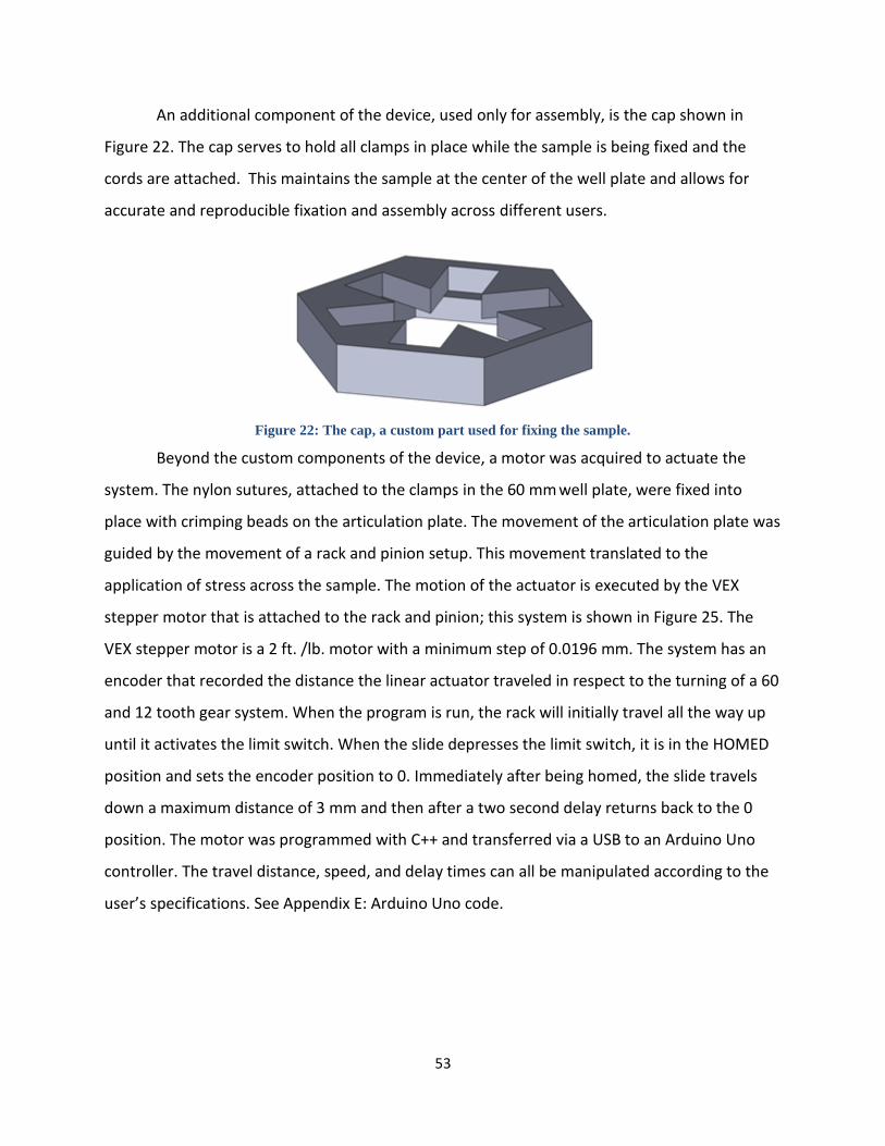
53
An additional component of the device, used only for assembly, is the cap shown in
Figure 22. The cap serves to hold all clamps in place while the sample is being fixed and the
cords are attached. This maintains the sample at the center of the well plate and allows for
accurate and reproducible fixation and assembly across different users.
Figure 22: The cap, a custom part used for fixing the sample.
Beyond the custom components of the device, a motor was acquired to actuate the
system. The nylon sutures, attached to the clamps in the 60 mm well plate, were fixed into
place with crimping beads on the articulation plate. The movement of the articulation plate was
guided by the movement of a rack and pinion setup. This movement translated to the
application of stress across the sample. The motion of the actuator is executed by the VEX
stepper motor that is attached to the rack and pinion; this system is shown in Figure 25. The
VEX stepper motor is a 2 ft. /lb. motor with a minimum step of 0.0196 mm. The system has an
encoder that recorded the distance the linear actuator traveled in respect to the turning of a 60
and 12 tooth gear system. When the program is run, the rack will initially travel all the way up
until it activates the limit switch. When the slide depresses the limit switch, it is in the HOMED
position and sets the encoder position to 0. Immediately after being homed, the slide travels
down a maximum distance of 3 mm and then after a two second delay returns back to the 0
position. The motor was programmed with C++ and transferred via a USB to an Arduino Uno
controller. The travel distance, speed, and delay times can all be manipulated according to the
user’s specifications. See Appendix E: Arduino Uno code.

54
Figure 23: The rack and pinion setup with motor.
4.5 C Dimensional Analysis
Before a comprehensive CAD model could be created, the dimensions of the device
needed to be established. In order to establish bounds, the necessary dimensions were
accounted for by first measuring from the inside outward. Starting with the skin sample size,
dimensions for a well plate were chosen, some room was allowed for the internal components
of the device, and a wall thickness for the shell was added. This gave a minimum value for the
spatial footprint of the device. Next, the dimensions were assessed from the outside in; the
outer dimensions of the available stock material served as the maximum outer bound of the
shell. Room was incorporated for the width of the shell, and a maximum inner space was
established. With these bounds for the size of the device, dimensions were chosen that kept
the spatial footprint in the incubator to a minimum, used the least material to reduce cost and
waste, and allowed for the greatest possible sample expansion within the size limits.
The device tested a circular skin sample with a 15mm diameter. The clamps, as seen in
Figure 24, extended 7.5mm off the sample in all directions creating an outer diameter of 30mm.
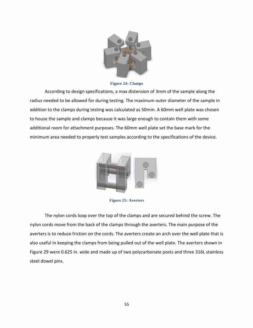
55
Figure 24: Clamps
According to design specifications, a max distension of 3mm of the sample along the
radius needed to be allowed for during testing. The maximum outer diameter of the sample in
addition to the clamps during testing was calculated as 50mm. A 60mm well plate was chosen
to house the sample and clamps because it was large enough to contain them with some
additional room for attachment purposes. The 60mm well plate set the base mark for the
minimum area needed to properly test samples according to the specifications of the device.
Figure 25: Averters
The nylon cords loop over the top of the clamps and are secured behind the screw. The
nylon cords move from the back of the clamps through the averters. The main purpose of the
averters is to reduce friction on the cords. The averters create an arch over the well plate that is
also useful in keeping the clamps from being pulled out of the well plate. The averters shown in
Figure 29 were 0.625 in. wide and made up of two polycarbonate posts and three 316L stainless
steel dowel pins.
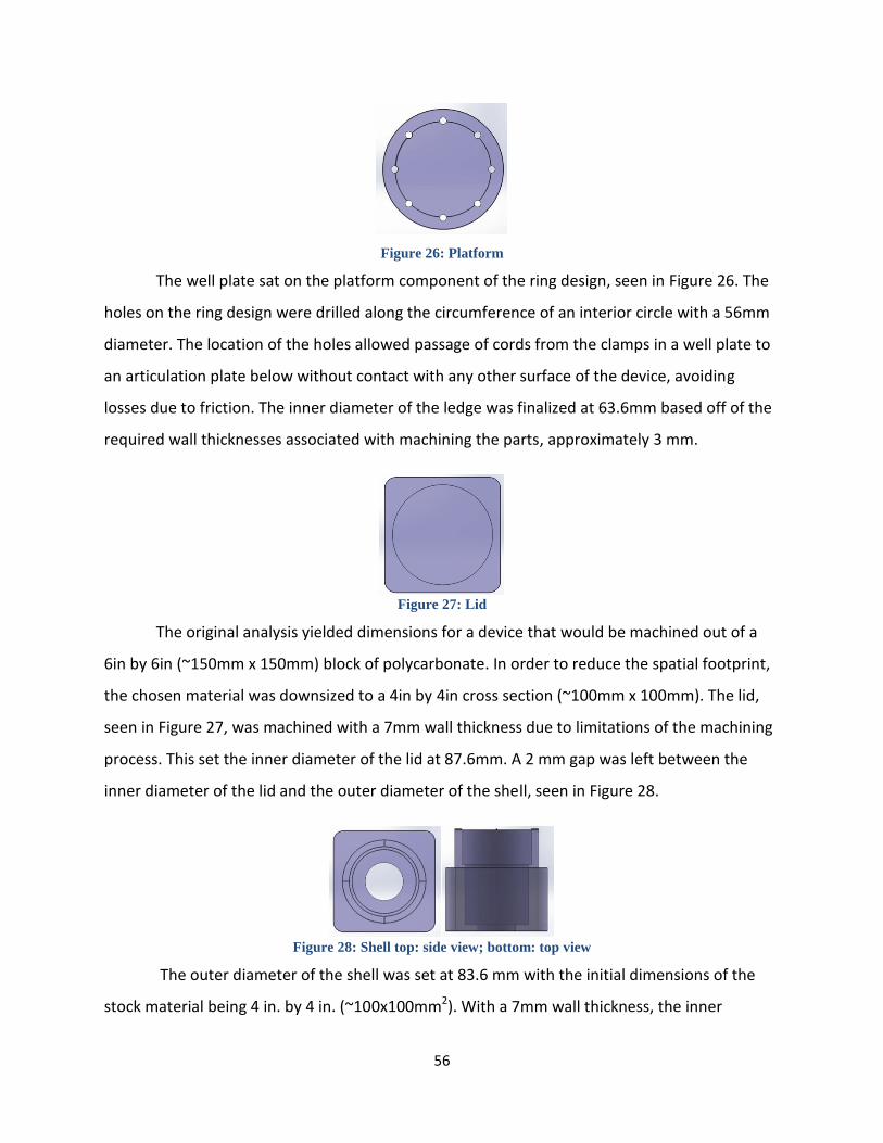
56
Figure 26: Platform
The well plate sat on the platform component of the ring design, seen in Figure 26. The
holes on the ring design were drilled along the circumference of an interior circle with a 56mm
diameter. The location of the holes allowed passage of cords from the clamps in a well plate to
an articulation plate below without contact with any other surface of the device, avoiding
losses due to friction. The inner diameter of the ledge was finalized at 63.6mm based off of the
required wall thicknesses associated with machining the parts, approximately 3 mm.
Figure 27: Lid
The original analysis yielded dimensions for a device that would be machined out of a
6in by 6in (~150mm x 150mm) block of polycarbonate. In order to reduce the spatial footprint,
the chosen material was downsized to a 4in by 4in cross section (~100mm x 100mm). The lid,
seen in Figure 27, was machined with a 7mm wall thickness due to limitations of the machining
process. This set the inner diameter of the lid at 87.6mm. A 2 mm gap was left between the
inner diameter of the lid and the outer diameter of the shell, seen in Figure 28.
Figure 28: Shell top: side view; bottom: top view
The outer diameter of the shell was set at 83.6 mm with the initial dimensions of the
stock material being 4 in. by 4 in. (~100x100mm2). With a 7mm wall thickness, the inner

57
diameter of the shell was set at 69.6mm. The top of the shell was castellated to space the lid
1mm off the rim to allow for regulated gas exchange. The ledge designed to hold the platform
was set at an inner diameter of 63.6 as stated earlier. This inner diameter allowed the platform
to rest securely and left a 2.5mm between the edges of the lip and the outer diameter of the
holes in the platform (see Figure 26: Platform).
Figure 29: Articulation Plate
The articulation plate seen in Figure 29 was designed to be smaller than the inner
diameter of the lip inside of the shell. The diameter was set at 58mm. Not only did this allow for
the articulation plate to be placed inside of the shell, but it also allowed free movement of the
plate in the vertical z axis of the device during tests. At the bottom of the plate, two columns
extended downward to create a site at which the plate can connect to the linear actuator. The
blocks were spaced 13mm apart with a hole bored and centered at 6.5mm below the lower
surface of the articulation plate and the 10.5mm from the vertical edge of the block. The linear
slide interfaced with the articulation plate between the two blocks to avoid any creation of a
moment during testing. A screw fixed the linear slide to the articulation plate. On the bottom
surface of the shell a hole was machined that grants the linear slide access to the inside of the
shell and the lower surface of the articulation plate. The linear slide measured 23mm at its
longest dimension for the cross sectional area. The hole was then bored with a diameter of
38mm to accommodate the slide comfortably. Calculations can be seen in Appendix A.8.
4.5 D CAD Drawings
Once the calculations were finalized and checked for accuracy, the model could proceed
to a CAD model. The CAD model was created on SolidWorks. All dimensions were input
according to the values specified in the dimension analysis. Fillets and chamfers were added to
the design to remove all sharp edges making it more user friendly as well as asthetically
pleasing. Each of the components of the design were inserted into an assembly and mated to
ensure the dimensions were accurate.

58
4.5 E Machining
The CAD model for the clamps was saved under the proper .stl format and sent to the
rapid prototyping quote request. The CAD models were uploaded into the computer-aided
machining (CAM) software ESPRIT. The CAM software sets each cutting pass the computer
numerical control (CNC) machine makes. The block of raw material must be faced first to
ensure a smooth cutting surface. The software includes features to turn down the outer
diameter of parts. This procedure was used for the shell, platform, and articulation plate.
Creation of pockets was used for the shell, lid, and articulation plate. Bore holes were created
in both the articulation plate and the platform. Chamfers and filletts were added to all parts.
The island pass removes material around a raised feature. Islands were used to castellate the
rim of the shell. The depth of cut of the shell created a unique problem for machining. Normal
tool sets contain a maximum cut length around 2.25in. Very few milling tools can reach a depth
of 4in from the top surface. Lathes can reach 4in but will cause deformation around the rim of
the part the deeper it goes. To overcome this problem, a bore bar was used to remove material
from the center of the stock material. This tool has a variable cutting diameter and can be
custom fit to reach greater depths than the other tools.

59
Design Verification Chapter 5:
5.1 Preliminary Data
The device needed to be capable of fulfilling the required objectives before it could be
used to evaluate the effects of mechanical loading on skin grafts. In order to establish the
functionality of our device, preliminary data was collected.
5.1 A Pullout Testing
Pullout testing was conducted for the first generation of clamps. Since rapid prototyped
parts cannot be tapped due to their hollow structure and loosely printed internal layers the
clamps were fixed using binder clips. An elastic sample of circular geometry was placed
between the clamps. A line was traced along the edge of the grips to set the zero line for the
pullout testing. A weight was attached to the sample and the sample was then raised to a
height of six inches off the table. The weights tested were 2kg, 1kg, and 0.1kg. The gravitational
force for each mass is 19.62N, 9.81N, and .981N respectively. The test yielded complete pullout
of the sample for each mass. The current base value for force applied by each clamp on the
sample was .941N. Results from testing were unacceptable for proper performance of device,
indicating that new clamps had to be designed.
Revisions were made to the design of the clamps in an iterative process; after continued
fabrication and pullout testing, it was determined that the design must be changed altogether.
Clamps resembling C-clamps were designed and fabricated from 316L stainless steel, and
withstood initial pullout testing with much greater performance than the initial designs.
Testing was performed on synthetic materials and then on porcine skin samples and the results
confirmed their efficacy.
5.1 B Force Calculations
A force value was determined for the particular loading of the skin sample. The sample
was approximated as a series of concentric rings of finite cross sectional area with an applied
pressure normal to the surface and radial outward from the center of the sample. Using the
equation σ=F/A, where σ=stress, F=applied force, A= cross sectional area yields;

60
→ F= .941N. This value of force is only a tentative value and will
be reevaluated once the proper research has been conducted to determine the proper model
for the system.
5.1 C Power Output Required for Motor
In order to select a motor a power calculation was conducted. The equation used was
in which P=power, F= force, d=total travel, t= time or 1/frequency. The force value
was used from the previous calculation. The value for frequency was obtained from the
specifications of the device that the testing cycle must be from 2s to 2 hours. A 2s cycle was the
highest frequency so that was the value used in the power calculation. The distance for travel
was generated from the limitation of available space. According to calculations, in Appendix
A.8, of the maximum distention with respect to the maximum stress, a travel of 5mm was more
than sufficient to stretch the sample and was not too long a distance that it extended beyond
the boundaries of usable space in the culture plate. The value generated was .02826W. That
value must then be multiplied by six to account for the force balance at the articulation plate
yielding0.16956 W, or 0.125ftlb/s. The value for the motor available to us from the robotics
department was 2ftlbs/s. This motor was capable of performing necessary functions as well as
accounting for losses due to friction and efficiency of the rack and pinion device.
5.1 D Rack and Pinion, Motor, and Load Cell
A stepper motor is a brushless, synchronous electrical motor that converts digital
vibrations into mechanical rotation (Omega Engineering). Every revolution of the stepper motor
is divided into a discrete number of steps and the motor must have a separate pulse for each
step. An advantage of the stepper motor is the precise positioning and repeatability of
movements, since steppers have 3 to 5% accuracy (Omega Engineering). Dr. Chin used a 6mm
stepper motor that was designed for voltages between 3 and 6 volts. The inertial moment of
the rotor is a minimum 0.7 kgm2 * 10-9, and the angular acceleration reaches 165 000 rad/s
which means that a power rating of between 125~250 mW can be achieved.
A load cell is defined as a transducer that converts an input mechanical force into an
electrical output signal. Load cells are commonly referred to as load transducers or load sensors

61
(FUTEK Advanced Sensor Technology). The S215 Ultra-Low Profile Point Load Cell is intended
for limited space applications requiring accurate measurement of full scale forces of 2, 4, and
12 lbf. It can be used with a rigidly mounted platform or to measure tensile or compressive
force. It has an extended battery life. Mounting is from the bottom to minimize the total height
of the assembly. Dr. Chin used this type of load cell in his device. Another load cell researched
was the Model 31 by Honeywell. This was also a miniature load cell with a rugged diaphragm
and male attachment threads. DermiGen used an older style heavy duty 2-mV/V output cell. A
limitation with the load cells is the extremely high cost.
The rack and pinion was evaluated for a motor with a power output of 2ftlbs/s and a
maximum angle of 180°. The maximum travel of the rack and pinion was determined using a 12
tooth gear. The vex 12-tooth gear has a radius of 7.404mm. For radial motion θ= s/r, where θ =
angle, s = arc length, and r=radius. For a rack and pinion set up, the linear slide will travel the
arc length of the gear as the gear travels θ. For a maximum angle of 180° and a radius of
7.404mm, the maximum travel will be 23.26mm. Since this is greater than the 10mm
specification, it is an acceptable set because the angle can be limited to set the maximum travel
at 10mm. Also for this motor, a minimum step distance was evaluated. The controller can
program 254 points. The minimum rotation angel θ* is equal to θ, the maximum angle, divided
by the total number of programmable points. For the motor obtained from the robotics
department, the minimum step angle is 0.0123° and applying the travel formula above, the
minimum displacement is 0.0916mm.

62
5.2 Design Feasibility
Initial experiments were performed to evaluate design feasibility on a basic, conceptual
level. A sample of porcine skin was used for the experiment, as seen in Figure 30. Pig skin was
chosen to test the proof of concept for the final design because pig skin is similar to human skin
in terms of hair follicles, sweat glands, and subcutaneous fat. Clips were attached to each side
of a square sample. The sample was stressed through cyclical loading first in the y-direction,
next in the x-direction, and finally in both directions at the same time. The skin appeared to
stretch evenly in all directions during the last test. The skin returned to its original position once
the stress was removed proving that the forces applied remained within the elastic retention
region for skin. The test showed that clips could stay attached to the sample during testing, and
it indicated, on a basic level, that equi-biaxial loading can apply a uniform load across the entire
sample.
Figure 30: Device proof of concept.
(Left) uniaxial stretch in the y-direction, (middle) in the x-direction, (right) equi-biaxial stretch
As the design process advanced toward a prototype, more sophisticated testing was
performed. With respect to theoretical analysis, ANSYS was used to evaluate the stress pattern
across the surface of the sample as an effect of the setup and testing conditions. The visual
results from the analysis can be seen in Figure 31. Simulated loads on each site for different
specified lengths simulated the size of the clamps used to attach the device to the sample. The
goal for this modeling was to achieve the smallest size grips that applied a uniform load across
the entire sample. This testing also enumerated the stress concentrations created by multiaxial
loading in order to confirm that the load was in fact uniform across the entire sample.

63
Figure 31: An ANSYS analysis of the device’s setup.
Moving on from theoretical and conceptual analysis, testing was done to assess the
feasibility of the prototype setup. A circular, 15 mm diameter porcine skin sample was sutured
in place. The skin sample that was being pulled was observed visually, and a relatively uniform
force was observed, as shown in Figure 32.
Figure 32: Initial testing of porcine skin in the prototype.

64
A materials/cost list was completed to determine if the required parts for this device
meet the budget of $508. Each part was specified in exact dimensions as well as the method of
creation of the part or method of acquiring the part. All costs were added up and compared to
the budget. An extensive list of parts and prices can be viewed in Appendix B.2. The total cost
amounted to $133 for the device and $140 total.

65
Discussion Chapter 6:
The main goal of this project was to design and fabricate a novel device that can
multiaxially stretch tissue-engineered skin grafts in vitro in order to improve the mechanical
integrity of the grafts and also accelerate growth. The end product successfully completed all
requirements. All objectives, functions, and specifications defined during the initial phase of
the project were met. The device was able to secure the sample, prevent slippage, perform
multiaxial stretch, vary the stress and strain rates, and apply stretch at the air liquid interface.
The sample was secured and slippage was prevented with the design and fabrication of
the clamps. The c-clamp design utilized an adjustable screw to apply adequate gripping force to
a discrete location on the sample and allow skin samples with different thicknesses to be
tested. Six clamps secured the sample at six equally spaced locations along the perimeter of the
sample Initial pullout testing suggested that pullout would not occur at the maximum allowable
force of 0.2N. During validation testing when samples were secured in the device and test
cycles were applied to different types of samples, there was no slippage observed for porcine or
chicken skin samples.
The device was able to perform multiaxial stretch with a rack and pinion actuation
system. A 2ft·lb VEX motor powered a series of gears to move a metal linear slide up and
down. This slide attaches to the articulation plate where cords run from the articulation plate to
the clamps. As the linear slide moved down, it pulled on the cords, and the clamps were pulled
radially outward. The uniform cord length pulls on each clamp at the same time inducing a
multiaxial stress on the strain on the sample. ANSYS finite element modeling was used to
display the deformed shape of the skin sample after a downward displacement of the slide. The
results show the uniformity of stress across the sample. The skin sample deformed evenly in all
directions, showing a large area of a uniform stress in the middle of the sample. This type of
loading can be defined as multiaxial because the deformation occurs along more than one or
two axes. The deformation of skin samples during testing was consistent with the finite element
model. It was important to apply multiaxial stretch as opposed to uniaxial stretch because skin
produced by the body grows in an environment with mechanical forces acting on it in all
directions.

66
The stresses and strain rates were customized with C++ programming. Parameters such
as displacement and velocity of the rack and pinion setup correlate with the strain and strain
rate of the sample being tested and the strain is directly related to the stress in the sample. The
velocity of the motor and the total number of steps the motor takes were able to be adjusted in
the code. Increasing the speed of the motor increased the strain rate induced on the sample
and increasing the displacement increased the total strain. This is useful for robust analysis of
the effects mechanical loading has of skin graft development.
The device was able to apply stretch at the air-liquid interface by keeping the sample
secure in a 60 mm2 well plate filled with DMEM medium. The clamps rest on the bottom
surface of the well plate and the sample rests on the lower surface of the c-clamps. This
relationship between well plate, clamps, and sample maintains the sample at consistent height
above the bottom of the well plate. The well plate can then be filled with the appropriate
amount of the medium to culture the sample at the air-liquid interface. To ensure that the
sample remains at the air-liquid interface during testing, the averters were developed. The
averters are designed to fit securely on any standard 60mm well plate while being easily
attachable and removable. They serve to prevent the sample from lifting out of the medium
when the cords are put in tension by redirecting the motion of the cords up and around the
edge of the well plate. They also work to minimize friction in the motion of the assembly.
6.1 Product Impact
Before using this device or putting it on the market for widespread use, it is important
to understand the varying impacts this device could have on the economic, political, societal,
and environmental status quo.
6.2 Environmental Impact
With regard to the environment, our novel skin stretching device should have a
negligible effect. There would be a small amount of waste generated from the manufacturing
of the device. The current machining process requires removal of material from stock pieces of
polycarbonate and 316 L stainless steel. Reclamation and recycling of waste material could be

67
implemented to further decrease waste products. Furthermore, with the exception of a
disposable 60mm well plate, every component of the bioreactor is autoclavable. Because it
was designed to be easily sterilizable, there would be little to no waste associated with use and
maintenance.
The device runs on electricity, so a certain amount of energy is lost during testing cycles;
however, the associated energy use is minimal, and the system could potentially be optimized
to require less power or test larger samples.
If the state of current skin substitutes were improved due to mechanical loading, the
field could focus on engineered tissues. Therefore, there would be less of a need for bovine or
porcine tissues. The improved stability of the grafts would decrease the incidence of second
applications.
6.3 Economics
This device could potentially impact the economy with regard to hospitals, insurance
companies, emergency medical care facilities, and hospital patients. A main problem associated
with current skin grafts is their high cost; a square foot of Integra or Dermagraft, two commonly
used skin grafts, costs ~$5600 or ~$12000, respectively (Bar-Meir, Mendes, & Winkler, 2006).
These costs are relative to the supplied size of the graft alone, and do not include the additional
medical expenses associated with surgeries and hospital stays. Some instances require
additional applications of skin grafts due to the inability of the initial graft to adhere and
integrate properly into the body. Additional graft treatments will increase the total medical
expenses. Our device can potentially decrease medical expenses by making grafts more
durable and easier to apply in practice. Better mechanical stability, easier implementation of
grafts, and less initial donor material will decrease the number of grafts needed for treatment
decreasing treatment time, ultimately decreasing medical expenses (Boyce, 1996).
6.4 Societal Influence
Our device has the potential to positively affect society. The accelerated growth and
improved mechanical integrity resultant from testing with our device will greatly improve skin
68
substitutes on the market today (Martin, 2004). Burn victims requiring skin grafts will be able to
receive treatment more quickly, skin grafts will be easier to handle during surgery decreasing
the difficulty of the surgeon’s task, effectively decreasing potential for graft failure, and it will
be possible to create more mechanically stable grafts at an increased rate. In addition, valuable
research can be conducted to study the effects of mechanical stimuli during culture and better
understand the phenomenon of mechanotransduction.
6.5 Political Ramifications
The skin stretching device will not influence global politics very much. People do suffer
from non-healing wounds all over the globe and in all countries. Many times the treatments of
those wounds are experimental and costly. For example one application of Apligraf costs
approximately $1,300 (Bar-Meir, Mendes, & Winkler, 2006). While healthcare systems around
the world can receive a positive influence from full scale implementation of this device, no
political motive can be ascertained, positive or negative, that would cause a meaningful impact.
6.6 Ethical Concerns
There are few ethical concerns associated with this device. The device was created for
future testing and stimulation of tissue-engineered grafts to improve their durability and
functionality thus improving the quality life of patients requiring skin grafts. Ethical concerns for
this device are the same as those associated with stem cells and artificial cell lines. Since this
device tests tissues incorporating fibroblasts, keratinocytes, or other cell lines from mice, use of
this device could receive the same criticism. Use of stem cells has been extremely controversial
over the past decades. In addition, gene exchange from one species to another, specifically
from animals to food products, has been a topic of debate. It is possible that, even if genetic
materials were procured using ethical and regulated protocols, some would still contend with
their use.
6.7 Health and Safety Issue
This device was designed with the intent to improve the current state of engineered skin
grafts; with that in mind, it is clear that health and safety are of the utmost importance with

69
regard to design intent. With regard to the standard of skin grafts, the device is designed to
improve the mechanical stability of tissue-engineered skin grafts. Enhanced grafts with
properties that are close to native skin will minimize the risk of tears or mechanical failure
during or after application. This structural integrity, while reaching that of autografts or
allografts, exceeds that of current skin substitutes. On a larger scale, this device enables a more
rapid approach to the fabrication of engineered tissues; an increase in the efficiency of
production can lead to a decrease in associated expense, resulting to an increase in availability
and a decrease in cost associated with skin grafts.
Beyond the health and safety of the patient that will receive the graft, safety of the user
of the device was a high priority throughout this design process. Within the ranked objectives
prioritizing the end-goal wants of this project, safety of the user was a main criterion, around
which many decisions were based. All components of the device are designed to have smooth
edges with either chamfers or fillets in machining. Additionally, no sharp objects such as suture
needles, pins, or hooks were chosen as the fixation methods for our device. With regard to
electrical hazards, the device can function properly in standard operating conditions of an
incubator, therefore no wire leads are exposed or pose any sort of risk. The samples used
during testing are tissue-engineered skin substitutes hydrated in a medium and should be
handled with caution and the proper personal protective equipment required for biohazard
material. The lid of the device is designed to eliminate the risk of substances splashing and
coming into contact with any sensitive parts of the body. Finally, every component of the
bioreactor portion of the device is sterilizable by autoclave, excluding the well plate, which is
disposable. The actuator portion can be treated with 70% ethanol. In all, the device is designed
to pose a negligible risk to the user while largely benefitting the health of the skin graft
recipient.
6.8 Manufacturability
This device is easily manufacturable and reproducible. The time required for machining
all components was less than 15 hours. All parts can be machined with readily available tools
such as a CNC machine or lathe. There are other methods such as injection molding that could

70
make the machining process easier. However, such a large scale option would only be
necessary if it went into full scale production. The materials required are polycarbonate and
316L stainless steel. If the polycarbonate were injection molded it would require much less time
and attention to reproduce all the parts. The clamps can be machined; however they require
much more skill to machine properly. 316L stainless steel has a 40% machinability rating and as
such needs to be carefully observed during the machining process. Knowledge of programming
would also be required to create a working code that can run the motor. Also parts such as a
motor, encoder, limit switch, and sleeve would need to be purchased separately and modified
to fit the design.
6.9 Sustainability
The device does not use any renewable energy or help to create any renewable energy.
It does not require an undue amount of energy for operation either. The device is designed to
run with only one motor and because of this does not require a lot of energy. The products
used to create this device are polycarbonate and 316L stainless steel. Producing these devices
on a larger scale would increase byproducts from the creation of these materials. With the
proper precautions to avoid harmful byproducts being placed into the ecosystem, this device
should have negligible impacts on the environment.

71
Validation Chapter 7:
7.1 Sterility and Gas Exchange
In order to ensure that the device could be used in an in vitro setting, while in contact
with biological items such as mammalian cells and medium, sterility validation was essential.
During the device’s testing regime, there will be a tissue sample along with medium in a culture
dish inside sitting on the stage plate. The dish will have no lid since the sample has to be
stretched. For this reason, it is necessary that the bioreactor portion of the device remains
sterile so that the tissue is not compromised throughout testing. The lid and the shell of the
bioreactor should maintain sterility while allowing gas exchange, similar to the functionality of a
standard culture dish. Additionally, the sleeve should form an airtight barrier with both the
bottom of the shell and the bottom of the articulation plate in order to allow motion while
preventing contamination. The chamber that must be kept sterile is illustrated in Figure 33, in
which sterile areas are denoted by blue and green dots.
Figure 33: An illustration of the internal sterile chamber of the bioreactor.

72
The device itself contains a polycarbonate lid, which was machined to have adequate
gas exchange so that the culture plate itself would not necessitate a lid. To validate that the
inside of the device would remain sterile during testing, the following procedure was
implemented and executed.
7.1 A Procedure
The bioreactor portion of the device (i.e. shell, lid, platform, articulation plate) and
forceps were autoclaved. DMEM with 2% FBS was aseptically added to two separate 60mm cell
culture dishes. The experimental plate was placed, with forceps, on the platform inside the
device without a lid, while the control plate was covered by a culture lid. The polycarbonate lid
was then placed on the device. The control plate and the device were placed in the incubator.
Both plates were imaged at 24, 48, and 72 hours, and changes in color, along with any
microorganism growth, were recorded.
There were clear signs to look for when checking for contamination inside the well
plates. One key sign in a contaminated dish was the change in medium color from a vibrant red
to a yellow-orange tint. Cell culture medium contains phenyl red which is a pH indicator; when
culture remains sterile and the medium is not contaminated, the pH remains near 7.0 and the
color of the medium is red. If the medium were contaminated the pH would decreases and the
color would change. Another clear sign of contamination would be the visual detection of
bacteria; for frame of reference, a bacterium at 20x magnification is shown in Figure 34.

73
Figure 34: An example of bacterial contamination at 20x magnification.
Compared to a 1mm scale with 100 divisions (0.01 mm).
Once experimentation confirmed that the device maintained sterility, gas exchange
would be tested to ensure that sufficient exchange was occurring. This was tested by placing
dry ice in water inside the device and replacing the lid. As the dry ice sublimated, carbon
dioxide should be seen diffusing out of the device, demonstrating proper gas exchange.
7.1 B Results
The team proved that the device is both sterile and allows adequate gas exchange
through the described validation procedures. The results of the sterility testing are shown
below in Figure 35, in which the color in both plates remained a vibrant red indicating no
change in pH.

74
Figure 35: No change in medium color of plates
To further validate the sterility, microscope images were captured of both plates at 20x
magnification. The images show no bacteria in the plates at a microscopic level. This is shown
in Figure 36 as compared to a 1 mm scale.
Figure 36: No bacterium contamination in 20x magnification
With validation of gas exchange, CO2 passage from the bioreactor to the outside
environment was visually observed during the dry ice procedure.

75
Conclusions and Recommendations Chapter 8:
8.1 Conclusions
After preliminary research and evaluation, the iterative design process, and fabrication a
final device was created that successfully applied multiaxial stretch to skin samples during
culture. The device was able to be sterilized and maintain a sterile culture environment. Testing
parameters of speed and displacement were able to be changed to fit the user’s needs. This
device can fit in an incubator and a biosafety cabinet. Also the device was completed within the
budget and time frame. Future modifications and testing will be needed to fully evaluate the
devices usefulness.
8.2 Recommended Analytical Data
It is recommended that testing on real skin samples is conducted to discover indications
of epidermal proliferation test samples. Once the device was created, testing on real samples
can begin. The time required for one test set limits the number of test groups possible. The skin
can be cultured under cyclic stress using the device alongside an unstretched control. Force
displacement values can be collected from the test sets. All data collected can then be analyzed
using MATLAB to obtain stress and strain values. Measurements can then be taken from the
grip distance as well as marker dots placed on the sample itself to see if the stresses and strains
were localized or globalized over the sample.
After the culture of the sample is complete, the histology of the sample can be analyzed.
The histological results look for three things: growth factors, damage to the tissue, and cell
proliferation. Growth factors can be evaluated from a comparison of growth factors in an
unstretched sample alongside a cyclically stretched sampled. Upregulation of growth factors
will be a good indicator that the cyclical testing is working. Growth factors should show an
upregulation of 120% at the end of testing, a value decided upon by the team. Damage to the
tissue can be determined through tallies of cell necrosis after the testing regime is completed.
This value will show a comparison of cells proliferated to cell death. Ideally the number of cells
created will be greater than the number of cells destroyed by the testing, which will also
hopefully show a minimization of tissue damage. Finally, cell proliferation can be tallied up to

76
determine the rate of production the device can yield. The rate of cells created per time of
testing should be 20% better than the original device for in vivo testing.
8.3 Characterization of Cells in Scaffold
In order for cells to be characterized in the scaffold, cell proliferation can be observed
using immunohistochemical staining that will be performed using the primary antibody against
Ki-67, MIB-1 (Orhan, 2006; Faratzis, 2009). The procedure of histological analysis works by
sectioning the tissue sample in 3 um section using paraffin. They will then be deparaffinized in
xylene and rehydrated using graded ethanol when they are ready to be stained. Ki-67 is a
proliferation associated nuclear antigen expressed in all cycling cells except resting cells in the
G0 phase. When the sections are stained using the clone MIB-1, cells that are in the G1, S, G2
and M phases of the cell cycle will be detected. The Ki-67 gene is present on the chromosome
10 (10q25).The half-life of Ki-67 protein has been estimated about 60-90 minutes (Faratzis, et
al., 2009). Ki-67 is a protein phosphorylated by serine and threonine with a crucial part in cell
division. This has been observed from the arrest of cell proliferation when Ki-67 is blocked
either by microinjection of blocking antibodies or by inhibition of dephosphorylation (Nabi,
Nagi, & Sami, 2008). The last step is counterstaining the sections with hematoxylin for 30
seconds, then dehydrating and mounting them. The count of Ki-67-positively stained nuclei will
be performed in areas of greatest density of stained cells within each section. About 1,000 cells
will be counted at a magnification of ×400. Ki-67 labeling index (LI) is defined as the number of
Ki-67-positive cell nuclei per 100 cells (Orhan, Kale, Cağlar, Göğüş, & Karaağaoğlu, 2006)
8.4 Future Modifications
It is recommended that a load cell be added to the device. The current setup can be
easily modified to accommodate a load cell between the articulation plate and the linear slide.
A load cell can be used to quantify the forces applied to the sample during testing. This active
feedback is extremely important because of the time dependent characteristics of skin such as
hysteresis. Over time the same displacement will induce a smaller stress in the sample as the
skin sample becomes more compliant. If this were to occur during testing, it would be prudent
for the device to incorporate a load cell.

77
Additionally, once a load cell is installed the programming on the Arduino Uno can be
modified to accept input from the load cell. The code can include a feedback loop that will
adjust the displacement of the rack and pinion setup in real time. As soon as the force applied
deviates from the original test parameters the feedback loop can increase or decrease the
displacement accordingly so that the force applied matches the intended value.

78
References
American Burn Association. (2011). National Burn Repository Report.
Balasubramani, M., & Ravi Kumar, T. (2001). Skin substitutes: A review. Burns, 27(5), 534-544.
Bannasch, H., Fohn, M., Unterberg, T., Bach, A., Weyand, B., & Stark, G. (2003). Skin tissue
engineering. Clinics in Plastic Surgery, 30(4), 573-573.
Bar-Meir, E., Mendes, D., & Winkler, E. (2006). Skin substitutes. Israel Medical Association
Journal, 8(3), 188-191.
Bischoff, J. E., Arruda, E. M., & Grosh, K. (2000). Finite element modeling of human skin using an
isotropic, nonlinear elastic constitutive model. Journal of Biomechanics, 33(6), 645-652.
Blackstone, B., & Powell, H. (2012). Morphogenesis and biomechanics of engineered skin
cultured under uniaxial strain. Advances in Wound Care, 1(2), 69-74.
Blotzik, E., & Scherer, M. (2008). Skin replacement therapies for diabetic foot ulcers: systematic
review and meta-analysis. Diabetes Care, 31(4), 693-694.
Bolland, F., Fisher, J., Ingham, E., Kearney, J., & Korossis, S. (2005). Bioreactors in Tissue
Engineering. Topics in Tissue Engineering, 1-23.
Bouzari, N., Kim, N., & Kirsner, R. S. (2009). Defense of the skin with LL-37. The Journal of
Investigative Dermatology, 129(4), 814.
Boyce, S. (1996). Cultured skin substitutes: a review. Tissue Engineering, 255-256.
Chin, M. S. (2010). In vivo acceleration of skin growth using a servo-controlled stretching device.
Tissue Engineering, 16.
Dantzer, E., & Braye, F. M. (2001). Reconstructive surgery using an artificial dermis (integra):
results with 39 grafts. British Journal of Plastic Surgery, 54(8), 659-664.
Daya, M., & Nair, V. (2008). Traction-assisted dermatogenesis by serial intermittent skin tape
application. Plastic and Reconstructive Surgery, 122(4), 1047-1054.

79
DeCarbo, W. T. (2009). Bilayered bioengineered skin substitute to augment wound healing. Foot
& Ankle Specialist, 2(6), 303-305.
DeFilippo, R., & Atala, A. (2002). Stretch and growth: the molecular and physiologic influences
of tissue expansion. Plastic and Reconstructive Surgery, 109(7), 2450-2460.
Denkler, K. (2008). Vacuum breast expansion: A look back at the history of this technique.
Plastic and Reconstructive Surgery, 122(3), 989-990.
DermiGen. (2012). A Tension Bioreactor System. Retrieved 2012, from Tissue Growth
Technologies: http://www.tissuegrowth.com/prod_skin.cfm
Erba, P., & Meile, L. (2011). A morphometrical study of mechanotransductively induced dermal
neovascularization. Plastic Reconstruction Surgery.
Faratzis, G., Tsiambas, E., Rapidis, A. D., Machaira, A., Xiromeritis, K., & Patsouris, E. (2009).
VEGF and ki 67 expression in squamous cell carcinoma of the tongue: An
immunohistochemical and computerized image analysis study. Oral Oncology, 45(7),
584-588.
Federico, S., Grillo, A., Giaquinta, G., & Herzog, W. (2008). Convex fung-type potentials for
biological tissues. Meccanica, 43(3), 279-288.
Fox, S. I. (2011). Human Physiology (12th ed.). New York City: McGraw-Hill.
Fung, Y. C. (1993). Biomechanics: Mechanical Properties of Living Tissues. New York City:
Springer-Verlag.
FUTEK Advanced Sensor Technology. (n.d.). Load Cells. Retrieved 2012, from FUTEK:
http://www.futek.com/product.aspx?t=load
Gale, E. A. (2002). The rise of childhood type 1 diabetes in the 20th century. Diabetes, 51(12),
3353-3361.

80
Gebelein, C. (1986). Polycarbonates in medical applications. Encyclopedia of Materials Science
and Engineering Vol.5, 3621-3623.
Ghattaura, A. S., & Potokar, T. S. (2009). Calcified integra membrane: One possible cause of skin
graft failure in the second stage of integra use. European Journal of Plastic Surgery,
32(1), 47-50.
Griffith, L. G. (2002). Emerging Design Principles in Biomaterials and Scaffolds for Tissue
Engineering. Annals of the New York Academy of Sciences, 961(1), 83-95.
Gutierrez, P. (2006). Cultured epithelial autografts. Australian Nursing, 13(11).
Hsieh, S., & Lin, W. (1999). Modulation of keratinocyte proliferation by skin innervation. Journal
of Investigative Dermatology, 113(4), 579-586.
Kishi, K., & Shimizu, R. (2012). Skin graft. Plastic Surgery International.
Leventon, W. (2002). Synthetic Skin. IEEE Spectrum, 39(12), 28-33.
Manning, D. D. (1973). Maintenance of skin xenografts of widely divergent phylogenetic origin
on congenitally athymic (nude) mice. Journal of Experimental Medicine, 138(2), 488-494.
Martin, I. W. (2004). The Role of Bioreactors in Tissue Engineering. Trends in Biotechnology,
22(2), 80-86.
Mathieu, D., Linke, J. C., & Wattel, F. (2006). Handbook on Hyperbaric Medicine. Netherlands:
Springer.
Menke, N. B., Ward, K. R., Witten, T. M., Bonchev, D. G., & Diegelmann, R. F. (2007). Impaired
wound healing. Clinics in dermatology, 19-25.
Metcalfe, A. D., & Ferguson, M. W. (2007, June 22). Tissue engineering of replacement skin: The
crossroads of biomaterials, wound healing, embryonic development, stem cells and
regeneration. Journal of the Royal Society, Interface, 4(14), 413-437.

81
Nabi, U., Nagi, A. H., & Sami, W. (2008). Ki-67 proliferating index and histological grade, type
and stage of colorectal carcinoma. Journal of Ayub Medical College, 20(4), 44.
National Instruments. (2003). Labview: Measurements Manual.
National Instruments. (2011). Teach Tough Concepts: Closed-Loop Control with Labview. 1-6.
Ní Annaidh, A., Bruyère, K., Destrade, M., Gilchrist, M. D., & Otténio, M. (2012).
Characterization of the anisotropic mechanical properties of excised human skin.
Journal of the Mechanical Behavior of Biomedical Materials, 5(1), 139-148.
O'Dell, M. (1998). Skin and Wound Infections: An Overview. American Family Physician, 2424-
2432.
Omega Engineering. (n.d.). Introduction to Stepper Motors and Drives. Retrieved 2012, from
OMEGA Engineering Technical Reference:
http://www.omega.com/prodinfo/stepper_motors.html
Orhan, D., Kale, G., Cağlar, M., Göğüş, S., & Karaağaoğlu, E. (2006). Histone mRNA in situ
hybridization and Ki 67 immunohistochemistry in pediatric adrenocortical tumors.
Virchows Archiv : an international journal of pathology, 448(5), 591-596.
Padbury, J. F. (2008). Skin—the first line of defense. The Journal of Pediatrics, 152(6), A2.
Pataky, T. C., Latash, M. L., & Zatsiorsky, V. M. (2005). Viscoelastic response of the finger pad to
incremental tangential displacements. Journal of Biomechanics, 38(7), 1441.
Pedersen, L., & Jemec, G. B. (2006). Mechanical properties and barrier function of healthy
human skin. Acta Dermato-Venereologica, 86(4), 308-308.
Philips, J. R., & Johnson, K. O. (1981). Tactile spatial resolution. III. A continuum mechanics
model of skin predicting mechanoreceptor responses to bars, edges, and gratings.
Journal of Neurophysiology, 46(6), 1204-1205.

82
Place, E., George, J., Williams, C., & Stephens, M. (2009). Synthetic polymer scaffolds for tissue
engineering. Chemical Society Reviews, 38(4), 1139-1151.
Powell, C., Smiley, B., Mills, J., & Vandenburgh, H. (2002). Mechanical stimulation improves
tissue engineered human skeletal muscle. American Journal of Physiology, 283(5),
C1557-1565.
Powell, J. (2006). Skin physiology. Surgery (Oxford), 24(1), 1-4.
Powell, J. (2006). Skin physiology. Surgery (Oxford), 24(1), 1-4.
Reichelt, J. (2007). Mechanotransduction of keratinocytes in culture and in the epidermis.
European Journal of Cell Biology, 86(11), 807-816.
Ruff, C., Holt, B., & Trinkaus, E. (2006). Who's afraid of the big bad wolff? "Wolff is law" and
bone functional adaptation. American Journal of Physical Anthropology, 129(4), 484-
498.
Sanders, J. E., Goldstein, B. S., & Leotta, D. F. (1995). Skin response to mechanical stress:
adaptation rather than breakdown--a review of the literature. Journal of rehabilitation
research and development, 32(3), 214.
Sanjeev, R., Naresh, M. D., & Arumugam, V. (1994). Effect of strain rate on the fracture
behaviour of skin. Journal of Biosciences, 19(3), 307-313.
Scanlon, V. C., & Sanders, T. (2011). Essentials of Anatomy and Physiology (6th Edition ed.).
Philadelphia, Pennsylvania: F.A. Davis Co.
Sen, C. K., Gordillo, G. M., Roy, S., Kirsner, R., Lambert, L., Hunt, T. K., & Longaker, M. T. (2009).
Human skinwounds: a major and snowballing threat to public heath and the economy.
Wound Repair and Regeneration, 17(6), 763-771.
Shevchenko, R. V., James, S. L., & James, E. S. (2010). A review of tissue-engineered skin
bioconstructs available for skin reconstruction. Journal of the Royal Society Interface,
229-258.

83
Shores, J. T., Gabriel, A., & Gupta, S. (2007). Skin substitutes and alternatives: a review.
Advances in Skin & Wound Care: The Journal for Prevention and Healing, 20(9), 493-508.
UK Medicines Information. (2001). New Drugs in Clinical Development. National Prescribing.
Retrieved from http://www.ukmi.nhs.uk/NewMaterial/Secure/apligraf.pdf
University of Michigan. (2012). Skin Banking. Retrieved 2012, from University of Michigan
Trauma Burn Center: Retrieved from
http://www.traumaburn.org/who/skinbank/banking.shtml
University of Michigan. (n.d.). Skin Banking. Retrieved 2012, from University of Michigan
Trauma Burn Center: Retrieved from
http://www.traumaburn.org/who/skinbank/banking.shtml
Weiss, J. A., Maker, B. N., & Govindjee, S. (1996). Full Text Online Finite element
implementation of incompressible, transversely isotropic hyperelasticity. Computer
Methods in Applied Mechanics and Engineering, 135(1), 107-128.
Wysocki, A. B., & Dorsett-Martin, W. A. (2008). Enhance your knowledge of skin grafts. Nurse,
30-38.
Yano, S., Komine, M., Fujimoto, M., Okochi, H., & Tamaki, K. (2004). Mechanical stretching in
vitro regulates signal transduction pathways and cellular proliferation in human
epidermal keratinocytes. The Journal of investigative dermatology, 122(3), 783-790.
Zöllner, A. M., Buganza Tepole, A., & Kuhl, E. (2012). On the biomechanics and mechanobiology
of growing skin. Journal of Theoretical Biology, 297, 166-175.
Zöllner, A. M., Buganza Tepole, A., Gosain, A. K., & Kuhl, E. (2012). Growing skin: Tissue
expansion in pediatric forehead reconstruction. Biomechanics and Modeling in
Mechanobiology, 11(6), 855-867.

84
Appendices
Appendix A: The Design Process
Appendix A.1 Gantt chart

85
Appendix A.2 Pairwise Comparison Chart

86

87

88

89
Appendix A.3 Metrics

90
Appendix A.4 Evaluation Matrix

91

92
Rank MeanPercent Ranking (100% =
completely fulfills function)
Deviaton from
top score
1st Clamps 89.22% 0%
2nd Glue 87.54% -2%
3rd Sutures 77.27% -12%
1st Expanding secured platform 89.22% 0%
2nd Motor 87.36% -2%
3rd Pressurize air/media 76.19% -13%
1st Negative feedback loop 98.50% 0%
2ndComputer program (LabView) 97.92%
-1%
3rd Cranks/Knobs 81.75% -17%
1st Use existing bioreactor 97.67% 0%
2nd Build bioreactor into device 96.30% -1%
3rd Create synthetic capillaries 86.81% -11%
Function: Prevent slippage/Secure Sample
Function: Perform controlled, multiaxial stretch
Function: Vary stresses and strain rates
Function: Allow access to media

93
Appendix A.5 Brainstorming
Design considerations

94
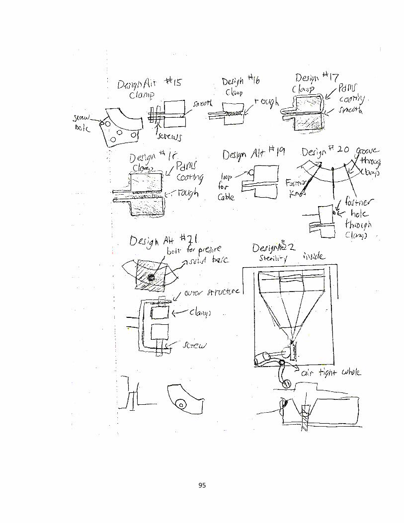
95

96

97
Appendix A.6 Conceptual Designs

98
Appendix A.7 Alternative Designs
Column Design
Column Design Pros Cons
*Allows for great control of the sample *Multiple data points can be taken from a single sample with varied conditions
*Requires sophisticated (and expensive) technology, equipment *Fabrication of such small parts may be too advanced and expensive for the team’s skill level and budget

99
Expanding Ring Design
Expanding Ring Design Pros Cons
*Only one motor to actuate in one direction *Less expensive *Easier to program and control *Easier to calculate applied loading than other less uniform methods of fixation
*Challenge to maintain sterility *Can only apply a uniform stretch, not as versatile as other designs

100
Custom Fit Device
Custom Fit Design Pros Cons
*Allows for significant variability in the desired size and shape of the sample *Enables a wide range of stretching cycles *Device could supply user with grafts of shapes and sizes tailored to his specific need
*Requires four motors that can move biaxially, independent of each other *Creates a challenge with sterility

101
Piston Device
Piston Design Pros Cons
*Least expensive – uses simple, traditional technology *Highly reproducible because motion is applied by one mechanical movement *Few parts means easy setup
*Pressure would be exerted uniformly so this device is less versatile than others *Using media to pressurize the sample introduces uncertainties *Small parts would be difficult to produce and load accurately and reproducibly

102
Appendix A.8 Calculations
Evaluation of new clamp design
Calculation of moments

103
Creation of prototype
Diameter calculation for lid and shell
Diameter calculation for platform and articulation plate

104
Dimension calculations for components of design

105
Appendix B: Expanding Ring Design
Appendix B.1 CAD Drawings
Component Picture Description
LID (Polycarbonate)
The lid must enable gas exchange while restricting the passage of contaminants from the
incubator, working identically to the tortuous path mechanism of a well plate lid.
SHELL (Polycarbonate)
The shell will house the entire device, with exception of the motor, and will be covered by
the lid to preserve sterility.
WELL PLATE (Polycarbonate)
The standard polystyrene 60 mm2 well plate will hold the sample and the medium.
CLAMPS (Medical Grade 316L Stainless
Steel)
The clamps (6) will grip the sample with a screw that enters at the top and grips the sample on the base. There will be a hole that is level with the sample that will connect to a cord that will
enable stretching of the sample.
AVERTERS (Posts:
Polycarbonate Pins: Stainless
Steel)
The averters (6) sit on the edge of the well plate and redirect the motion of the cords so that the clamps’ path of motion remains level with the
sample but the cords are able to pass around the side of the well plate.
PLATFORM (Polycarbonate)
The platform will be the support structure for the well plate, and will have holes through which
cords can pass to stretch the sample. The platform will sit atop a lip running across the inner circumference of the shell and held in
place. ARTICULATION
PLATE (Polycarbonate)
The articulation plate will be in the lower portion of the shell and has holes through it to articulate with each cord, and will be actuated by a motor
that connects to the bottom by a screw. SLEEVE
The sleeve will be secured in an air-tight manner to the articulation plate and the shell and will be
expandable without exerting a supporting or resisting force on the system. As the motor raises and lowers the articulation plate, the
sleeve will maintain that barrier necessary for sterility without restricting motion.

106
The Cap for fixation

107

108

109

110
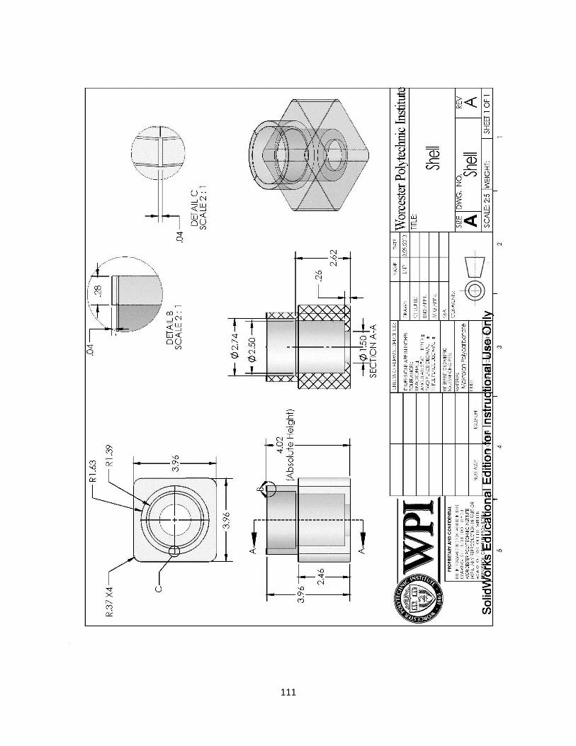
111

112

113

114

115

116

117

118
Appendix B.2 Budget list
Expenses
Device
Part Quantity Purchase Cost Unit Cost Cost for Assembly
Bioreactor 1 $55.14 $73.17
> Lid 1 $5.00 $5.00 $5.00
> Shell 1 $5.00 $5.00 $5.00
> Averter 6
> > Post 12 $8.00 $0.67 $8.00
> > Pin 18 $7.59 $0.42 $7.59
> Clamp 6 $3.16 $0.53 $3.16
> Suture 6 $15.50 $15.50 $15.50
> Well Plate 1 $19.20 $0.96 $0.96
> Platform 1 $5.00 $5.00 $5.00
> Articulation Plate 1 $5.00 $5.00 $5.00
> Screw 6 $4.50 $0.18 $1.08
> Sleeve 1 $16.88 $16.88 $16.88
Actuator 1 $139.14 $140.04
> Linear Slide 1 $14.95 $14.95 $14.95
> VEX Rack 1 $19.99 for kit $19.99 $19.99
> Universal Joint 1 $2.56 $2.56 $2.56
> VEX 60 tooth gear 1 $12.99 for gear kit $12.99 $12.99
> VEX stepper motor 1 $20.00 $20.00 $20.00
> Limit Switch 1 $12.99 $12.99 $12.99
> VEX Encoder 1 $19.99 $19.99 $19.99
> Arduino Uno 1 $25.00 $25.00 $25.00
> VEX Bracket 1 $9.99 $5.00 $5.00
> Screw 6 $4.50 $0.18 $1.08
> Drive Shaft 1 $5.49 $5.49 $5.49
Total Device $194.27 $213.21
Lab Fee $100.00
Lab Notebook $7.00
Total Cost $320.21
Total Budget $608
Net Budget Remaining $287.80

119
Appendix B.3 Parts list
Device Component: Part Quantity Material Vendor Part Number Description
Bioreactor 1
> Lid 1Makrolon
PolycarbonatePiedmont Plastics MA-28303246
top of device encloses testing setup,
polycarbonate
> Shell 1Makrolon
PolycarbonatePiedmont Plastics MA-28303247
outer enclosure of device,
polycarbonate
> Averter 6
> > Post 12Makrolon
PolycarbonatePiedmont Plastics MA-28303248
inserts that attach to rim of well plate,
polycarbonate and 316 stainless steel
> > Pin 18316 Stainless
SteelMcMaster-Carr 97395A445
> Clamp 6316L Stainless
SteelOnline Metals T-316/316L
fixtion part for testing, 316 L stainless
steel
> Suture 6 Nylon AD Surgical N/A standard medical sutures, nylon
> Well Plate 1 Polystyrene Corning Life Sciences 326160mm standard culture dish,
polystyrene
> Platform 1Makrolon
PolycarbonatePiedmont Plastics MA-28303247
resting location of well plate,
polycarbonate
> Articulation Plate 1Makrolon
PolycarbonatePiedmont Plastics MA-28303248
Location of cord insertion,
polycarbonate
> Screw 6316 Stainless
SteelMcMaster-Carr 92185A073
> Sleeve 1 Neoprene The Rubber Store BT-1090Encloses bottom to ensure sterility,
neoprene
Actuator 1
> Linear Slide 1 Steel VEX P/N: 276-1096metal slides that translate rotational
motion into linear motion
> VEX Rack 1 Delrin VEX P/N: 276-1957 Articulates with gear
> Universal Joint 1 Acetal SDP-SI A 5M 8-D206provides free roation of articulation
plate
> VEX 60 tooth gear 1 Delrin VEX P/N: 276-2169 articulates with rack
> VEX stepper motor 1 N/A VEX P/N: 276-2162 provides motion for actuator
> Limit Switch 1 N/A VEX P/N: 276-2174 sets home point for motor
> VEX Encoder 1 N/A VEX P/N: 276-2156 counts steps of motor
> Arduino Uno 1 N/A Mouser Electronics 782-A000066 micro-controller
> VEX Bracket 1 Steel VEX P/N: 276-1926houses motor, linear slide, rack, and
gear
> Screw 6 Steel McMaster-Carr 91251A051 provide attachment
> Drive Shaft 1 Steel VEX 276-2011 connects gear to motor

120
Appendix C: Operating Instructions
Appendix C.1 Programming
This Code will run a vex motor connected to a vex rack gear by a 60 tooth gear. The
system has an encoder recording distance traveled connected to the 60 tooth gear by a 12
tooth gear. There is a limit switch located at the top of the slide movement. The slide will first
travel all the way up until it activates the limit switch when the slide depresses the limit switch
it is in the HOMED position and will set the encoder position to 0. Immediately after being
HOMED, the slide will travel down to the distance described in the variable travel height. For
the user these parameters are changeable with the capability to vary the wait time between
stretching and the maximum displacement of the slide.
*/
#include "Arduino.h"
#include <Servo.h>
//encoder variables
#define encoder0PinA 2
#define encoder0PinB 3
volatile int encoder0Pos = 0;
//Limit Switch variables
#define c_LimitPin 4
volatile bool _Home;

121
Change how fast the motor turns
Change to set the desired position below the home position that you want to move in mm
Change to set the number of ticks you want gear to move. For this particular motor 1 tick=.445mm
//Servo Motor variables
#define c_ServoPin 9
int servoSpeed = 75; //How fast the motor turns Values 0<90
down 90 = stopped 90<180 up
int servoStop = 90;
double travelHeight = 10; // mm
double travelTicks =0; // (calculated
later)
Servo myservo; // create servo object to control a servo
// a maximum of eight servo objects can be created
// sequence variables
bool Homed = false;
bool Finished = false;
void setup() {
//encoder Setup
pinMode(encoder0PinA, INPUT);
pinMode(encoder0PinB, INPUT);

122
Calculated smallest step value for motor per movement = .445mm
// encoder pin on interrupt 0 (pin 2)
attachInterrupt(0, doEncoderA, CHANGE);
// encoder pin on interrupt 1 (pin 3)
attachInterrupt(1, doEncoderB, CHANGE);
//limit switch setup
pinMode(c_LimitPin, INPUT); //sets Limit pin as an input
digitalWrite(c_LimitPin, HIGH); //Turn on pullup resistors
//Servo motor setup
myservo.attach(c_ServoPin,1000,2000); // attaches the servo on pin 9 to the servo
object
//calculate number of ticks to go
travelTicks = (travelHeight/.445); // .445 mm/tick
//Serial communication rate
Serial.begin (9600);
}

123
Sets HOMED (zero) position where screw hits the limit switch
Change wait time (seconds) between stretches. In the code it is described as the “delay”
//do stuff here
void loop(){
if(Finished == false){
//Home the encoder so zero is at the
highest postion
if (Homed == false){
if(digitalRead(c_LimitPin) == HIGH){
myservo.write(130);
delay(2);
Serial.print(" NOT Home");
Serial.print("\n");
}
else{
myservo.write(servoStop);
encoder0Pos = 0;
Homed = true;
Serial.print(" Home ");
delay(2000);
}

124
}
else{
if (encoder0Pos < travelTicks){
myservo.write(servoSpeed);
}
else{
myservo.write(servoStop);
Serial.print("\n");
Serial.print(encoder0Pos);
Serial.print("ticks\n");
Serial.print(travelTicks);
Serial.print("ticks\n");
delay(2000);
Homed= false;

125
Appendix C.2 Test Preparation
1. Preparation of Cords
Nylon cords should be cut double actual cord length because they are doubled up when
being attached. In total, there should be 6 sets of cords for all 6 clamps.
2. Sterilization
Components of the device made out of makrolon polycarbonate (shell, lid, articulation
plate, and stage plate), 316 stainless steel (clamps), nylon (cords), and rubber (sleeve)
can be sterilized through autoclave.
The metal linear actuator can be sprayed with ethanol.
The 60 mm2 culture plate is disposable and can be changed when needed, as long as its
packaging remains sterile.
3. Preparation of Cords (Continued)
Once all components are sterilized, they should be removed from packaging inside a
fume hood.
The cords should have weights hung weights at the ends overnight to be pre-
conditioned (90% UTS).
This step allows cords to pre-creep, which will avoid creep later during testing.
It also causes cords to assume generally standard dimensions relative to one another.

126
Appendix C.3 Device Assembly
In the fume hood, place sleeve into the shell
Attach the 6 averters to the culture place using the holes on the platform as a
placement guide as seen in the image below
Thread the cords in between the neck on the clamps and the screw
Run cords up and around the averters through the holes in the platform down to the
articulation plate as seen in the image below

127
Once threaded through the articulation plate, mark points on the cords that are
consistent on all cords
Crimp these marked points with silver beads
Screw metal linear slide to the bottom of the articulation plate as seen in the image
below
Place components into the shell, with linear slide attaching to rack and pinion system
underneath as seen in the images below
Appendix C.4 Device Operation
Sample preparation
Acquire desired tissue sample and place in fume hood

128
Orient the clamps so the sample is fixed by all 6 clamps, equally spaced, as seen in the
image below
Use the “cap” to hold the clamps at a fixed location
Screw each individual clamp to secure the sample
Remove “cap”
Hydrate sample with saline solution so it maintains its viscoelastic properties for longer
testing cycle durations. More solution may need to be added depending on the
duration of testing.
Sample is ready for testing
Testing protocol
Fill medium in culture dish once tissue sample is secure at an air-liquid interface
Place control tissue sample (non-stretched) in culture dish
Place lid on device and move both device and control into incubator
Plug in battery into actuator portion of device, if using an outlet an outlet, plug into wall
Turn switch on
Check periodically depending on testing duration
When testing cycle has ended, remove device carefully following the reverse of the
fixation protocol
Section and fix samples for histology
Stain slides using ki-67 antigen

129
Observe cell proliferation in both experiment and control using microscope
Take ratio of proliferating cells/non-proliferating cells
Analyze data

130
Appendix C.5 Comprehensive Code
Code written by Timothy Sharood, adapted relative to experiments:
/*
Linear actuator Code
Tim Sharood
3/28/13
This Code will run a vex motor connected to a vex rack gear by a 60 tooth gear.
The system has an encoder recording distance traveled connected to the 6o tooth
gear by a 12 tooth gear. There is a limit switch located at the top of the slide
movement. The slide will first travel all the way up until it activates the limit
switch. when the slide depresses the limit switch it is in the HOMED position and
will set the encoder position to 0. Immediately after being homed the slide will
travel down to the distance described in the variable travelHeight.
*/
#include "Arduino.h"
#include <Servo.h>
//encoder variables
#define encoder0PinA 2
#define encoder0PinB 3

131
volatile int encoder0Pos = 0;
//Limit Switch variables
#define c_LimitPin 4
volatile bool _Home;
//Servo Motor variables
#define c_ServoPin 9
int servoSpeed = 75; //How fast the motor turns Values 0<90 down 90 = stopped
90<180 up
int servoStop = 90;
double travelHeight = 10; // mm change to set the desired postion below the home
postion that you want to move in mm
double travelTicks =0; // number of ticks to move (calculated later)
Servo myservo; // create servo object to control a servo
// a maximum of eight servo objects can be created
// sequence variables
bool Homed = false;
bool Finished = false;

132
void setup() {
//encoder Setup
pinMode(encoder0PinA, INPUT);
pinMode(encoder0PinB, INPUT);
// encoder pin on interrupt 0 (pin 2)
attachInterrupt(0, doEncoderA, CHANGE);
// encoder pin on interrupt 1 (pin 3)
attachInterrupt(1, doEncoderB, CHANGE);
//limit switch setup
pinMode(c_LimitPin, INPUT); //sets Limit pin as an input
digitalWrite(c_LimitPin, HIGH); //Turn on pullup resistors
//Servo motor setup
myservo.attach(c_ServoPin,1000,2000); // attaches the servo on pin 9 to the servo
object
//calculate number of ticks to go

133
travelTicks = (travelHeight/.445); // .445 mm/tick
//Serial communication rate
Serial.begin (9600);
}
//do stuff here
void loop(){
if(Finished == false){
//Home the encoder so zero is at the highest postion
if (Homed == false){
if(digitalRead(c_LimitPin) == HIGH){
myservo.write(130);
delay(2);
Serial.print(" NOT Home");
Serial.print("\n");
}
else{
myservo.write(servoStop);

134
encoder0Pos = 0;
Homed = true;
Serial.print(" Home ");
delay(2000);
}
}
else{
if (encoder0Pos < travelTicks){
myservo.write(servoSpeed);
}
else{
myservo.write(servoStop);
Serial.print("\n");
Serial.print(encoder0Pos);
Serial.print("ticks\n");
Serial.print(travelTicks);
Serial.print("ticks\n");
delay(2000);
Homed= false;
}

135
}
}
else{
delay(5000000);
}
}
void doEncoderA(){
// look for a low-to-high on channel A
if (digitalRead(encoder0PinA) == HIGH) {
// check channel B to see which way encoder is turning
if (digitalRead(encoder0PinB) == LOW) {
encoder0Pos = encoder0Pos + 1; // CW
}
else {
encoder0Pos = encoder0Pos - 1; // CCW
}
}
else // must be a high-to-low edge on channel A

136
{
// check channel B to see which way encoder is turning
if (digitalRead(encoder0PinB) == HIGH) {
encoder0Pos = encoder0Pos + 1; // CW
}
else {
encoder0Pos = encoder0Pos - 1; // CCW
}
}
}
void doEncoderB(){
// look for a low-to-high on channel B
if (digitalRead(encoder0PinB) == HIGH) {
// check channel A to see which way encoder is turning
if (digitalRead(encoder0PinA) == HIGH) {
encoder0Pos = encoder0Pos + 1; // CW
}
else {
encoder0Pos = encoder0Pos - 1; // CCW

137
}
}
// Look for a high-to-low on channel B
else {
// check channel B to see which way encoder is turning
if (digitalRead(encoder0PinA) == LOW) {
encoder0Pos = encoder0Pos + 1; // CW
}
else {
encoder0Pos = encoder0Pos - 1; // CCW
}
}
}