Novel methods of ozone generation by micro-plasma concept ...
18
General rights Copyright and moral rights for the publications made accessible in the public portal are retained by the authors and/or other copyright owners and it is a condition of accessing publications that users recognise and abide by the legal requirements associated with these rights. Users may download and print one copy of any publication from the public portal for the purpose of private study or research. You may not further distribute the material or use it for any profit-making activity or commercial gain You may freely distribute the URL identifying the publication in the public portal If you believe that this document breaches copyright please contact us providing details, and we will remove access to the work immediately and investigate your claim. Downloaded from orbit.dtu.dk on: Feb 04, 2022 Novel methods of ozone generation by micro-plasma concept Final report Fateev, Alexander; Chiper, Alina Silvia; Chen, Weifeng; Stamate, Eugen Publication date: 2008 Document Version Publisher's PDF, also known as Version of record Link back to DTU Orbit Citation (APA): Fateev, A., Chiper, A. S., Chen, W., & Stamate, E. (2008). Novel methods of ozone generation by micro-plasma concept: Final report. Risø National Laboratory for Sustainable Energy.
Transcript of Novel methods of ozone generation by micro-plasma concept ...

General rights Copyright and moral rights for the publications made accessible in the public portal are retained by the authors and/or other copyright owners and it is a condition of accessing publications that users recognise and abide by the legal requirements associated with these rights.
Users may download and print one copy of any publication from the public portal for the purpose of private study or research.
You may not further distribute the material or use it for any profit-making activity or commercial gain
You may freely distribute the URL identifying the publication in the public portal If you believe that this document breaches copyright please contact us providing details, and we will remove access to the work immediately and investigate your claim.
Downloaded from orbit.dtu.dk on: Feb 04, 2022
Novel methods of ozone generation by micro-plasma conceptFinal report
Fateev, Alexander; Chiper, Alina Silvia; Chen, Weifeng; Stamate, Eugen
Publication date:2008
Document VersionPublisher's PDF, also known as Version of record
Link back to DTU Orbit
Citation (APA):Fateev, A., Chiper, A. S., Chen, W., & Stamate, E. (2008). Novel methods of ozone generation by micro-plasmaconcept: Final report. Risø National Laboratory for Sustainable Energy.

1
Plasma and Technology Programme National Laboratory for Sustainable Energy Technical University of Denmark Frederiksborgvej 399, P.O. 49 Roskilde-4000 Denmark
FINAL REPORT
PSO PROJECT NO 2006-1-6839 NOVEL METHODS OF OZONE GENERATION BY
MICRO-PLASMA CONCEPT Authors A. Fateev, A. Chiper, W. Chen and E. Stamate
February 2008
2
1. Introduction
The project was planed as a supplement to already running PSO-2006-1-6365 project devoted
to plasma-assisted DeNOx. Ozone is as a key agent in plasma NOx reduction because in a
many step process it oxidizes NO to N2O5. The latter could be efficiently removed by a
scrubber system. The main objective of the project is optimization of ozone production based
on micro-plasma concept in order to reduce energy costs for ozone generation and total costs
for plasma DeNOx.
Dielectric barrier discharges (DBD) are widely used for ozone production in
pure oxygen or in dry air in various commercially available ozone generators. In the past
years, many investigations have been carried out in order to improve ozone generation
efficiency in terms of ozone concentration (g/Nm3) and ozone yield (g/kWh). Unfortunately
for a conventional DBD geometry used in most of all ozone generators, it is difficult to get
both high ozone concentration and high ozone yield values. The ultra-short gap barrier
discharge and the surface discharge were developed to generate high ozone concentration in
pure oxygen [1]. Ozone generation efficiency in air decreases to about half of that in pure
oxygen because the oxygen content in air is 21%, and a lot of applied energy to the system is
consumed to vibrational ‘pumping’ of N2 (X, v’’>0) states. A short-gap electrode system
increases the electric field in the gap (at the same applied voltage) and the mean electron
energy. Since the density of low-energy electrons (2-3 eV), which mainly decompose ozone,
decreases, it is possible to obtain a high concentration of ozone. Furthermore, the shift in
electron energy distribution function towards higher mean electron energy reduces vibrational
pumping of nitrogen molecules and therefore leads to a better utilization of applied energy for
ozone production. In recent years, new types of plasma devices based on a micro-plasma
concept have been developed. The micro-plasma is a plasma generated in very small spaces
with characteristic dimension of a few hundreds micrometers. There are two types of micro-
plasma devices: micro-hollow cathode discharge (MHCD) and capillary plasma electrode
discharge (CPED). High values of reduced electric field can also be obtained in micro-plasma
discharges [2]. As it is well-known, ozone generation efficiency increases in the transition
from streamer-type DBD to atmospheric pressure glow DBD [3]. In general, stabilization of

3
atmospheric pressure plasma can easily be achieved if the plasma is confined in small (≈ 50
Debye length) dimensions.
In the MHCD concept the generation of oxygen atoms (from which ozone is
formed) is separated spatially from the ozone production, because the ozone formation
appears outside the micro-plasma. Therefore, the formed ozone will not be destroyed by the
plasma, which in conventional ozonizers limits the upper achievable ozone concentration
(ozone saturation effect). The MHCD concept is useful in the sense that the ozone
concentration enhancement is at about the same value of ozone yield as when pure oxygen is
used as a feed gas.
The concept of CPED includes both micro-plasma jets produced when
capillaries cover one or both electrodes of a conventional DBD and a stable uniform glow-like
discharge uniformly distributed over the discharge gap. Our calculations show that capillaries
re-distribute energy input into plasma when dry air is used as a feed gas. Consequently, the
ozone yield is enhanced to about the same or to even higher ozone concentration. This is
important because ozone production from pure oxygen is more expensive than production
from dry air.
The project aims were to
• perform a feasibility study of ozone generation by modeling of micro-plasmas based
on either MCHD or CPE-discharges;
• develop and optimize an MCHD array for operation with pure oxygen in order to
enhance ozone concentration to about the same ozone yield achievable for commercial
available ozone generators;
• develop, investigate and optimize a CPE-discharge for operation with dry air in order
to enhance ozone yield to about the same or even higher ozone concentration than
achievable with commercial available ozone generators.

4
2. Feasibility study of ozone generation by micro-plasma devices
2.1 Effect of plasma volume reduction on mean electron energy Reduction of linear dimensions of plasma leads to many remarkable effects. One is a shift in
the electron energy distribution function. Thus, a decrease of the electrode gap from 1 mm to
0.3 mm increases the mean electron energy from 4.8 eV to 6.2 eV in a N2(80%)+O2(20%) gas
mixture as shown in Figure 1 (green and red circles, respectively on curves 2 and 3).
In pure oxygen the same reduction of discharge gap from 1 mm to 0.3 mm
causes less gain in the mean electron energy: from 6.5 eV to 7.2 eV, Figure 1 (blue circles I
and II, respectively in curve 1). Calculations have been done for various gas temperatures
(Tgas) and electron densities (Ne) typically realized in MHD and CPED in O2 and
N2(80%)+O2(20%) mixture:
MHD: Tgas=1500 K, Ne=1x1015 cm-3; (1)
Figure 1: Mean electron energy calculated for various reduced electric filed values in pure O2 (blue) and N2(80%)+O2(20%) mixture (red and green curves).

5
and
CPED: Tgas=500 K, Ne=5x1015 cm-3; (2)
CPED: Tgas=300 K, Ne=1x1014 cm-3; (3)
A change in electron energy distribution function with reduction of the discharge
gap leads in general to a shift towards electronic excitation/ionization and therefore reduces
energy attenuation to vibrational excitation. The latter effect is important in the case of
N2(80%)+O2(20%) mixture as it will be shown below.
2.2 Ozone generation in atmospheric pressure micro-hollow discharge in oxygen Ozone formed in various discharges by well-known three-body reaction of oxygen atoms and
oxygen molecules. Oxygen atoms itself are produced due to (pre-) dissociation of oxygen
molecules excited in collisions with electrons. Fast side reactions of oxygen atoms with
oxygen molecules and already formed ozone reduce both the steady-state oxygen and the
ozone concentrations or by other words the efficiency of ozone production [4].
Figure 2: Ozone formation in oxygen plasma afterglow. Plasma exists during time marked by red filled rectangle. Numbers on dashed horizontal lines (left) correspond to different initial O concentrations and corresponding ratios of O3:O2 are shown under the curves (right).

6
Calculations show that the complete conversion of O to O3 can only be obtained
if the relative concentration of oxygen atoms O:O2 stays below 10-4. As it can be seen from
Figure 2 the characteristic time of ozone formation is a few microseconds. This is the key
feature of MHD approach for ozone generation which has been successfully used by S. Ishii’s
group [1, 5]. Due to high current, extremely small plasma volume (residence time in plasma
1-2 μs) and fast gas expansion an efficient dissociation of oxygen takes place and ozone is
produced outside of the plasma region in absence of electrons.
Reduction of the discharge gap from 1 mm to 0.3 mm (at constant value of
applied voltage) increases significantly the reduced electric field but lives unchanged the
mean electron energy (see Figure 1). More detailed calculations show that the energy for
oxygen ionization at 0.3 mm increases compare to 1 mm, Figure 3 (curve 6, blue ovals I and
II).
Figure 3: Fractional power partition into different excitation processes in O2 plasma at different values of E/n and Tgas=1800K, Ne=1x1015 cm-3. Blue ovals correspond to E/n values at 1 mm (I) and 0.3 mm (II).

7
In opposite, energy input into O2 vibrational excitation decreases, Figure 3
(curve 1). The ratio O2+:O2(v’’) increases with rise of E/n, Figure 3 (right axes). Thus at 0.3
mm gap the ratio O2+:O2(v’’) becomes 1.6 times higher than at 1 mm gap. Electron-ion
recombination O2++e finally leads to the production of O atoms. However, as it can also be
seen from Figure 3 (curves 4, 5) the fraction of O2 electronically excited states, which are also
responsible for O atom generation, decreased. Therefore the O net production is expected to
be the same. Thus a micro-plasma device like MCD can be efficiently used to enhance the
ozone concentration but not the ozone yield.
Although pervious consideration has been devoted to ozone generation in MHD,
the main results will remain the same in case of CPED in pure oxygen.
2.4 Ozone generation in atmospheric pressure capillary plasma electrode discharge in air A unique feature of the CPED compared to other parallel plate DBD configurations is the
ability (at certain condition) to generate plasma jets in small (0.1-0.3 mm) capillaries [2].
Reduced electric field in these jets can reach higher values compare to that in the rest part of
the plasma volume. Therefore CPED is a promising device for ozone generation in air as it
will be shown below.
In air discharges the presence of the nitrogen ions, nitrogen excited (in
particular, metastable) molecules and atoms increases the complexity of the reaction system
[6]. Thus dissociation and excitation of nitrogen molecules lead to a number of additional
reactions involving nitrogen atoms and excited molecules that can provide additional channels
for oxygen atoms and finely ozone generation:
N + NO → N2 + O (4)
N + NO2 → N2O + O (5)
N2(A,B) + O2 → N2 + O + O (6)
N2(A) + O2 → N2O + O (7)

8
About half of the ozone formed in air discharges results from the oxygen atoms
produced in these indirect processes. As a result ozone formation in air takes about 100 μs [6].
A substantial fraction of electron energy lost in collisions with nitrogen molecules acts as
“pumping” for the ground vibrational states, N2(X, v’’>>1). Moderate gas temperature in the
plasma jets of CPED, 400-500K compared to that in MHD, 1500K, reduces significantly the
NO/NO2 formation which causes intensive ozone consumption (discharge poisoning). The gas
temperature outside jets is significantly lower.
Calculations of fractional power partition show that reduction of discharge gap
causes enhancement of nitrogen and oxygen ionization (Figure 4, curves 3,5) and significantly
reduces energy attenuation by vibrational “pumping” of N2(X, v’’) (curve 1). Energy input
into N2 and O2 electronic excitation does not significantly change in the range of interest for
E/n (green and red ovals). The ratio [N2++O2
+]:[N2(v’’)+O2(v’’)] increases with E/n (right axis
in Figure 4). At 0.3 mm gap ratio [N2++O2
+]:[N2(v’’)+O2(v’’)] becomes 5 times higher
compare to that at 1 mm gap. Since NO is always produced in discharges in air in the
following reactions:
N + O + M → NO + M, (8)
O(1D) + N2O → NO + NO, (9)
N2(A) + N2O → N2 + N + NO, (10)
A shift in electron energy distribution function towards ionization will enhance
1) N and O atom generation; and consequently ozone formation and 2) NO concentration.
Therefore the net ozone concentration in CPED will not be different in comparison with
conventional DBD, but ozone yield is expected to be higher.

9
3. Experimental studies of ozone generation by various micro-plasma devices 3.1 Experimental observation of shift towards ionization/excitation in curved dielectric barrier discharge operating with synthetic air
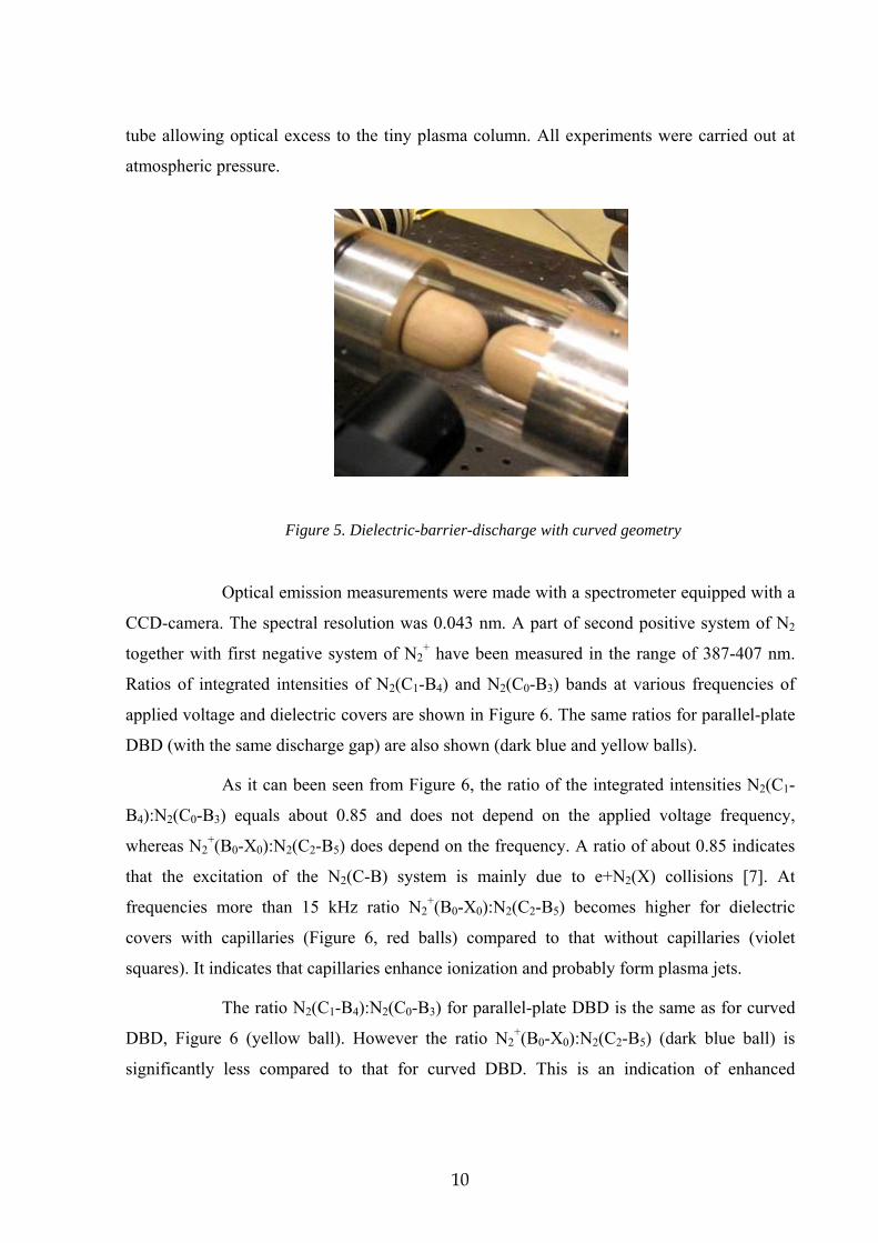
For this experiment a curved dielectric barrier discharge system (see Figure 5) was built.
Half-sphere aluminium electrodes were covered by replaceable STENAN® dielectric covers.
One pair of covers has single micro-holes Ø=300 μm, whereas the other one does not. Micro-
holes are placed in front of each other when they are mounted on the electrodes. Distance
between electrodes is variable from 0 mm to 10 mm. An ac-power supply with variable
frequency has been used in order to produce plasma. Electrodes are enclosed into a quartz
Figure 4: Fractional power partition into different excitation processes in N2(80%)+O2(20%) plasma at different values of E/n and Tgas=500K, Ne=5x1015 cm-3. Green and red ovals correspond to E/n values at 1 mm (I) and 0.3 mm (II), respectively.
10
tube allowing optical excess to the tiny plasma column. All experiments were carried out at
atmospheric pressure.
Optical emission measurements were made with a spectrometer equipped with a
CCD-camera. The spectral resolution was 0.043 nm. A part of second positive system of N2
together with first negative system of N2+ have been measured in the range of 387-407 nm.
Ratios of integrated intensities of N2(C1-B4) and N2(C0-B3) bands at various frequencies of
applied voltage and dielectric covers are shown in Figure 6. The same ratios for parallel-plate
DBD (with the same discharge gap) are also shown (dark blue and yellow balls).
As it can been seen from Figure 6, the ratio of the integrated intensities N2(C1-
B4):N2(C0-B3) equals about 0.85 and does not depend on the applied voltage frequency,
whereas N2+(B0-X0):N2(C2-B5) does depend on the frequency. A ratio of about 0.85 indicates
that the excitation of the N2(C-B) system is mainly due to e+N2(X) collisions [7]. At
frequencies more than 15 kHz ratio N2+(B0-X0):N2(C2-B5) becomes higher for dielectric
covers with capillaries (Figure 6, red balls) compared to that without capillaries (violet
squares). It indicates that capillaries enhance ionization and probably form plasma jets.
The ratio N2(C1-B4):N2(C0-B3) for parallel-plate DBD is the same as for curved
DBD, Figure 6 (yellow ball). However the ratio N2+(B0-X0):N2(C2-B5) (dark blue ball) is
significantly less compared to that for curved DBD. This is an indication of enhanced
Figure 5. Dielectric-barrier-discharge with curved geometry

11
ionization in curved geometry (with higher E/n values) compared to the flat one (with smaller
E/n values).
A constant ratio N2(C1-B4):N2(C0-B3) of about 0.85 for all geometries and
frequencies is in agreement with calculations shown in Figure 4: energy input into electronic
excitation of N2 has weak influence in E/n values. In opposite curved geometry and micro-
holes support increase of E/n and therefore enhance ionization [7].
3.2 Ozone production by micro-hollow cathode discharge operating in pure oxygen atmosphere
For this experiment, a micro-hollow cathode discharge system (see Figure 7) for ozone
production was built. The parallel-plate electrodes geometry is shown schematically. The
electrodes of 50 mm in diameter are made of molybdenum plates with 200 μm thickness.
There are 19 holes in each electrode with 300 μm as diameter. Each electrode is assembled in
a heavy metal holder. The dielectric barriers are made of alumina with 300 μm thickness. The
Figure 6. Ratios of integrated intensities N2(C1-B4):N2(C0-B3) and N2
+(B0-X0):N2(C2-B5) bands at various frequencies and dielectric covers arrangements. Dark blue and yellow balls at 15 kHz correspond to parallel-plate DBD.

12
dielectric spacer is sandwiched by the two heavy holders. The system was tested by applying
an AC bias to electrodes with pure oxygen as input gas. It was observed that the discharge
was localised at one hole and the dielectric spacer suffered some damage. This is because the
dielectric spacer is too thin and its surface is bigger than the electrode’s holders surface. This
problem may be solved by using a dielectric spacer with smaller surface than the surface of
the electrode’s holder.
Figure 7. Schematic drawing and pictures of the micro-hollow cathode discharge system.
3.3 Ozone production by capillary plasma electrode discharge operating in pure oxygen atmosphere Within the experiment a new discharge system (see Figure 8) for cold plasma production was
built. The system can be run in either CPED mode or in DBD mode. The symmetrical
parallel-plate electrodes geometry for both modes and the corresponding discharge pictures
molybdenum electrodes, thickness: 200 μm
discharge area, hole diameter : 300 μm
gas in
gas out electrode’s holder

13
are shown in right side of Figure 8. The dielectric barriers are made of alumina of 1 to 4 mm
thick. The upper electrode is connected to the HV power supply by using an interlock, while
the lower electrode is grounded. The discharge was excited by using a 14 kHz sinusoidal
wave voltage, with variable amplitude between 34 to 42 kV. The electrodes are cooled with
flowing air. The inter-electrode gap is adjustable between 3 mm up to 6 cm.
Figure 8. Pictures of the discharge system for either capillary plasma discharge or dielectric barrier discharge and their schematic drawings.
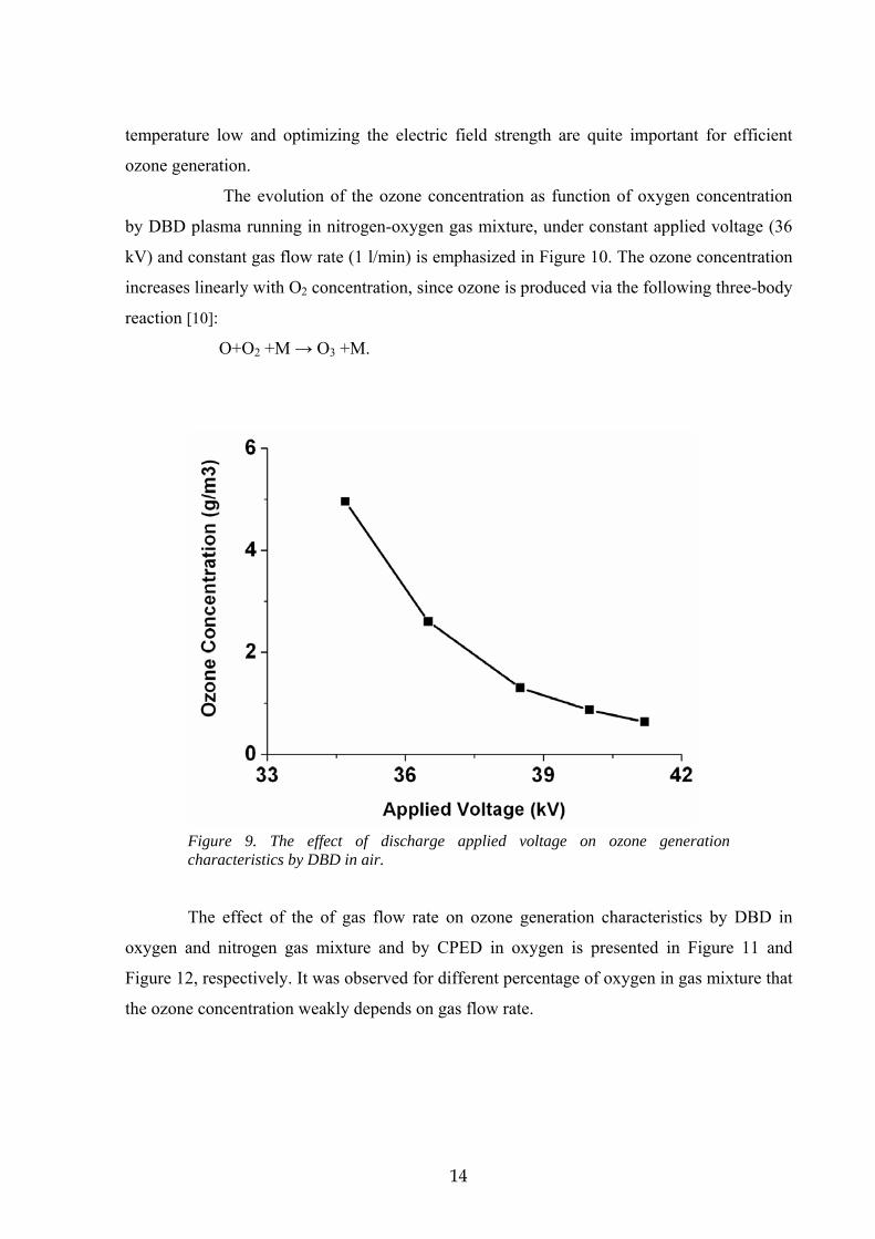
Figure 9 shows the relationship between ozone concentration and applied
voltage (discharge power density) by DBD running in dry air (1 l/min). The ozone
concentration decreases with increasing applied voltage. The phenomenon that ozone
concentration decreases with increasing applied discharge voltage (specific discharge energy)
is peculiar to ozone generation from air; it never appears in ozone generation from oxygen
[9]. The reason for this is as follows: (1) the concentration of the by-product NOx increases
with increasing specific energy; (2) gas temperature increases with increasing discharge
power density. These effects result in the promotion of ozone decomposition by the reaction
with nitrogen oxides because most of the rate coefficients related to the ozone decomposition
increase exponentially with increasing gas temperature. Therefore, keeping both the gas
DBD plasma in dry air
CPED - discharge in O2
gas in
HV electrode
ground electrode
gas out
Ozone absorption measurements
HV
14
temperature low and optimizing the electric field strength are quite important for efficient
ozone generation.
The evolution of the ozone concentration as function of oxygen concentration
by DBD plasma running in nitrogen-oxygen gas mixture, under constant applied voltage (36
kV) and constant gas flow rate (1 l/min) is emphasized in Figure 10. The ozone concentration
increases linearly with O2 concentration, since ozone is produced via the following three-body
reaction [10]:
O+O2 +M → O3 +M.
Figure 9. The effect of discharge applied voltage on ozone generation characteristics by DBD in air.
The effect of the of gas flow rate on ozone generation characteristics by DBD in
oxygen and nitrogen gas mixture and by CPED in oxygen is presented in Figure 11 and
Figure 12, respectively. It was observed for different percentage of oxygen in gas mixture that
the ozone concentration weakly depends on gas flow rate.

15
Figure 10. The effect of oxygen concentration on ozone generation characteristics by DBD in oxygen and nitrogen gas mixture.
Figure 11. The effect of gas flow rate on ozone generation characteristics by DBD in oxygen and nitrogen gas mixture.

16
Figure 12 shows the effect of gap distance on ozone generation characteristics by
CPED discharge in pure oxygen. Decreasing gap distance increases mean electron energy
and decreases the number density of low-energy electrons (2-3 eV) that mainly decompose
ozone [1]. Therefore, a higher concentration of ozone (about 17%) was obtained in CPED
discharge decreasing the gap distance from 6 mm to 3.5 mm, keeping constant the applied
voltage and gas flow rate.
Figure 12. The effect of gas flow rate on ozone generation characteristics by CPED in pure oxygen for different gap distances.
Conclusions 1) The feasibility study proved the potential use of micro hollow cathode and capillary plasma
electrode discharges for efficient ozone production in pure oxygen atmosphere.
2) Three new devices have been built and used for ozone production in oxygen and air.
i) The curved dielectric barrier discharge shows a clear indication of enhanced
ionization (higher E/n values) compared to the flat dielectric barrier discharge;
ii) The micro-hollow cathode discharge was tested with AC bias to electrodes
with pure oxygen and air as input gas. The discharge was localised to a few or just one hole
causing local damage by heat. In order to avoid this situation a new design based on thin film
coating directly on the ceramic plate was proposed and will be built in a near future.

17
iii) A capillary plasma electrode discharge that can also operate in dielectric
barrier discharge mode was tested for different applied voltages, gas flow rates and inter-
electrode gaps. Keeping the gas temperature low and optimizing the electric field strength
lead to efficient ozone generation. Decreasing the gap distance reduced the low energetic
electrons that mainly decompose ozone thus leading to higher ozone concentrations.
Since the issue of efficient ozone generation is yet very important for the
ongoing project PSO-2006-1-6365 the present experiments will be continued including
further characterization and optimization of the micro-hollow cathode setup and capillary
plasma electrode discharge as to achieve higher concentrations and yields of ozone. The
results following these modifications will be reported in the final report of PSO-2006-1-6365.
References [1] A. Yamatake, K. Yasuoka, S. Ischii, Jpn. J. Appl. Phys. 43 (2004) 6381.
[2] K.H. Becker, K.H. Schoenbach, J.G. Eden, J.Phys.D: Appl.Phys. 39 (2006) R35.
[3] M. Kogoma, S. Okazaki, J.Phys.D: Appl.Phys. 27 (1994) 1985.
[4] B. Eliasson, M. Hirth, U. Kogelschatz, J.Phys.D: Appl.Phys. 20 (1987) 1421.
[5] K. Yasuoka, A. Yamatake, Y. Yamura, H. Watanabe, S. Ischii, J.Adv.Technol. 7 (2004)
138.
[6] U. Kogelschatz, Plasma Chem. Plasma Process. 23 (2003) 1.
[7] A. Fateev, E. Stamate, P.K. Michelsen, Proceedings (CD-ROM). 28th International
conference on phenomena in ionized gases (ICPIG XXVIII), Praqgue (CZ), 15-20 Jul 2007.
Schmidt, J.; Simek, M.; Pekarek, S.; Prukner, V. (eds.), (Institute of Plasma Physics AS CR,
Prague, 2007) p. 1078-1081
[8] A. Fateev, F. Leipold, B. Stenum, Y. Kusano, E. Tsakadze, H. Bindslev, Plasma Proc.
Polym. 2 (2005) 193.
[9] J. Kitayama, M. Kuzumoto, J. Phys.D: Appl.Phys. 32 (1999) 3032.
[10] R. Ono, T. Oda, J. Phys. D: Appl. Phys. 40 (2007) 176.