
Notifier Little Black Book - notifierfiresystems.co.uk · 4 5 Fire System Design Any design should...
76
LITTLE BLACK BOOK of Fire Detection and Alarm Systems System Design Point Detection Beam Detection Air Sampling (Aspirating) Detection Voice Alarm Emergency Voice Communication Central Battery Systems Paging Systems
Transcript of Notifier Little Black Book - notifierfiresystems.co.uk · 4 5 Fire System Design Any design should...

LITTLE BLACK BOOKof Fire Detection and Alarm Systems
System DesignPoint DetectionBeam DetectionAir Sampling (Aspirating) DetectionVoice AlarmEmergency Voice CommunicationCentral Battery SystemsPaging Systems

2 3
Notifier by Honeywell: Little Black Book
IntroductionThis guide provides a basic overview to anyone involved in the design or action of a fire detection system. It will identify the current legislative requirements as well as clarify the responsibilities placed on the three key roles involved with the provision of a new system, namely the Designer, Installer and Commissioning Engineer, as well as remind the End User or Owner/Occupier what part they play in ensuring that the best possible system is supplied to protect life and property from fire.
It is important that everyone involved is conversant with the current British Standard Codes of Practice BS5839-1:2013 for general buildings and BS5839 -6:2013 for dwellings including those of multiple occupancy. The Installer should also be conversant with the British Standard relating to general wiring BS 7671.
The “Little Black Book” is intended to offer practical advice and is not a substitute for any of the standards or legislation referred to including: Regulatory Reform Fire Safety Order 2005The Equality Act 2010 (formerly the Disability Discrimination Act 1995)Building Regulation Approved Document Part BBuilding Regulation Approved Document Part MTechnical Booklet R under the Building Regulations (Northern Ireland) 2000Section 4 of Non-Domestic Technical Handbook (Scotland)
All these documents in some way affect what is included in the system. However the Owner/Occupier is ultimately responsible for the level of protection provided.
It is recommended that the Owner/Occupier carries out a Fire Risk Assessment to identify the level of protection required i.e. one of the categories detailed within BS5839-1:2013 (L1,L2,L3,L4,L5,M,P1 or P2 )
The full responsibilities of the Owner/Occupier are detailed within the Regulatory Reform Fire Safety Order (RRO) that replaced the majority of existing laws within the UK from Oct 2006.
New in this EditionChanges to BS5839-1 (2013)The principal changes introduced by this new edition have been summarised in the “Fire System Design” Chapter (page 7
Changes to BS5839-8 (2013) “PA/VA Public Address and Voice Alarm” chapter updated in line with changes introduced by BS5839-8:2013.
The Use of Visual Alarm Devices (VADs)The “Audible & Visual Alarms” chapter has been updated to include more detailed information on the use of Visual Alarm devices in line with EN54-23 and the recent changes to BS5839-1.
Fire System Remote ConnectivityInformation has been included on the use of Graphical User Interfaces (GUI) and remote monitoring of fire detection and alarm systems.
Fire System Design - Roles and Responsibilities
Fire System Categories - Deciding on the level of protection required
Detection and Alarm Zones
Detecting Fire
Detection Overview
Point Detection - Location and Spacing
High Sensitivity Laser Point Detection
Beam Detection
Air Sampling (Aspirating) smoke detection
Audible & Visual Alarms
Choice & Siting of Alarm Sounders
Visual Alarm Devices
PA/VA Public Address and Voice Alarm
EVCS - Emergency Voice Communication Systems
Paging Systems
Central Battery Systems and Emergency Lighting
Eliminating Nuisance Alarms
Advanced System Configuration and Connectivity
Cause and Effect
Dependencies and Delays
Graphics Systems and Remote Monitoring
Quick Detector Selection Guide
Notifier InfoPoint AppEasy access to a variety of sales and technical resources any time, anywhere.

4 5
Fire System DesignAny design should be prepared by a competent individual/organisation, who has consulted all interested parties and created a set of drawings, a specification, a cause & effect or fire plan, a list of Variations and completed a H1 Design certificate, detailed within BS5839-1:2013.
If designs are undertaken without this research being carried out, the fire detection system is unlikely to comply with the legal requirements. This could result in prosecution of the parties involved, particularly those within the supply chain as well as the Owner/Occupier.
WARNING: Anyone who takes on the responsibility for design will do so at their own risk and design liability insurance is advisable.
Notifier by Honeywell: Little Black Book

6 7
The Designer’s Responsibilities
• Agree the level of protection or category with Owner/Occupier
• Justify any Variations and document reasons
• Detail the detection & alarm zones
• Prepare specification and drawings including;
• Siting of manual call points
• Siting of point type heat and smoke detectors
• Siting of beam detectors
• Siting of any other forms of detection
• Specify type of cable for each circuit
• Specify type of system and equipment
• Include detail for on/off site links with other equipment
• Take into account the risk of false alarms – use the ‘pull out’ application guide at the back of this booklet
• Allow for correct level of sounders and visual alarms
• Prepare a fire plan or cause and effect chart
• Sign a H1 design certificate
Note BS5839-1:2013 recommends that a fire detection system is designed by a competent person, who takes responsibility for completing the design and signing off a ‘Design certificate’ H1. This should not be confused with other certificates relating to Installation H2 and Commissioning H3, that are completed by the parties responsible for those parts.Also if the contract allows, it is suggested that the Designer witness tests the completed system to ensure the original design is still appropriate – the Design certificate can then be completed after any amendments are included.
Fire System DesignNotifier by Honeywell: Little Black Book
Recent Changes to BS5839-1BS5839 part 1 was most recently updated in 2013. The principal changes introduced by this new edition are as follows:
1. The title has been modified to more accurately reflect the scope and content of this part of BS 5839.
2. The importance of providing accurate and unambiguous information to staff in residential care premises about the location of a fire has been highlighted in Clause 4.
3. A definition of “zone plan” has been added to the terms and definitions (Clause 3), with additional guidance added to subclause 6.1 and Clause 23, and new recommendations added to subclauses 42.2, 46.2 and 47.2. This is reflected in the sample acceptance certificate in H.4.
4. Item e) of 7.2 has been modified to emphasize the importance of identifying and recording agreed variations. 5. A definition of “visual alarm device” has been added to the terms and definitions (Clause 3), with a new recommendation on such devices added to subclause 11.2.
6. Table 4 of the 2002 edition, “Limits of ceiling height (Category P systems and five minute fire and rescue service attendance)”, has been deleted.
7. Clause 15 has been updated with guidance and recommendations on the provision of automatic transmission of fire alarm signals.
8. The guidance and recommendations of Clause 19 and subclause 35.2.7 have been updated to address the need to avoid delay in summoning the fire and rescue service when the fire detection and fire alarm system of a residential care premises operates.
9. The dimension of the width covered by the optical beam detector given in Figure 13 has been corrected to 18.75 m.
10. Subclause 45.1 now highlights that routine servicing of a fire detection and fire alarm system does not constitute a fresh review of system design, so that non compliance with this standard might not be identified during such servicing.
11. The wording of Annex C has been altered to further highlight the normative status of this annex.
12. A new Annex F has been added containing useful information on visual alarm device illumination characteristics from LPCB CoP 0001 [1]. Copyright is claimed on Annex F. Copyright holders are BRE Global Limited, Bucknalls Lane, Watford, Herefordshire, WD25 9XX, and the Fire Industry Association, Tudor House, Kingsway Business Park, Oldfield Road, Hampton, Middlesex, TW12 2HD. LPCB CoP 0001 is periodically updated and the latest edition needs to be consulted.
13. It is now recommended that major variations from the recommendations of this standard are recorded in the system logbook [see 7.2e)].
14. The term “care home” has been substituted throughout the document with “residential care premises”.
15. The term “fire service” has been substituted throughout the document with “fire and rescue service”.
16. The term “responsible person” has been removed and replaced with references to “premises management” to avoid confusion with the term defined in legislation.

8 9
Fire System CategoriesBefore a fire protection system can be designed, it is necessary to define the main objectives of the system. This is normally determined by a fire risk assessment, and should be provided as part of the fire system specification. BS5839 Part 1: 2013 defines three basic categories of fire detection system.
Notifier by Honeywell: Little Black Book

10 11
Category L3: Intended to offer early enough notification of a fire to allow evacuation before escape routes become smoke logged. Protection should be as for category L4 with the addition of smoke or heat detectors in rooms opening onto escape routes.
Category L2: Objectives are similar to category L3, however additional protection is provided for rooms at higher risk. Protection should be as for category L3 plus smoke detectors in specified rooms at high risk and documented within specification
Category L1: The highest category for the protection of life. Intended to give the earliest possible notification of a fire in order to allow maximum time for evacuation. Automatic and manual fire detection installed throughout all areas of the building. Smoke detectors should be employed wherever possible to protect rooms in which people can be expected to be present.
Similarly to class M systems, all alarm signals given in a category L system must be sufficient to warn all those people for whom the alarm is intended to allow for a timely evacuation.
Protection of voids should be considered in line with the protection category and fire risk assessment.
nw od
Canteen Kitchen Pantry
O�ce O�cePaperStore
nw od
Canteen Kitchen Pantry
Office OfficePaperStore
nw od
Canteen Kitchen Pantry
Office OfficePaperStore
Category M SystemsCategory M systems rely on human intervention, and use only manually operated fire detection such as break glass call points. A category M system should only be employed if no one will be sleeping in the building, and if a fire is likely to be detected by people before any escape routes are affected.
Any alarm signals given in a category M system must be sufficient to ensure that every person within the alarm area is warned of a fire condition.
Category L SystemsCategory L systems are automatic fire detection systems intended to protect life. The category is further subdivided as follows:
Category L5: In a category L5 system certain areas within a building, defined by the fire system specification, are protected by automatic fire detection in order to reduce the risk to life. This category of system may also include manual fire protection.
Category L4: Designed to offer protection to the escape routes from a building. The system should comprise Category M plus smoke detectors in corridors and stairways
Fire System Categories
nw od
Canteen Kitchen Pantry
Office OfficePaperStore
nw od
Canteen Kitchen Pantry
Office OfficePaperStore
nw od
Canteen Kitchen Pantry
Office OfficePaperStore
Notifier by Honeywell: Little Black Book

12 13
Category P SystemsCategory P systems are automatic fire detection systems whose primary objective is to protect property.
The category is subdivided as follows:
Category P2: Intended to provide early warning of fire in areas of high hazard, or to protect high-risk property. Automatic fire detection should be installed in defined areas of a building.
Category P1: The objective of a category P1 system is to reduce to a minimum the time from the ignition of a fire to the arrival of the fire brigade. In a P1 system, fire detectors should be installed throughout a building. In a category P system, unless combined with category M, it may be adequate for alarm signals simply to allow fire fighting action to be taken, for example a signal to alert a responsible person to call the fire brigade.
nw od
Canteen Kitchen Pantry
Office OfficeMAX DISTANCE <45M
1.4m
Fire System Categories
nw od
Electric Plant Materials Storage
Computer Equipment
nw od
Electric Plant Materials Storage
Computer Equipment
Notifier by Honeywell: Little Black Book
Manual call pointsPeople can often still detect a fire long before automatic fire detectors; hence manual call points are important components of fire detection systems in occupied buildings to ensure timely evacuation in the case of fire. All call points should be approved to EN54-11, and should be of type A, that is once the frangible element is broken or displaced the alarm condition is automatic.
Manual call points should be mounted on all escape routes, and at all exit points from the floors of a building and to clear air. It should not be possible to leave the floor of a building without passing a manual call point, nor should it be necessary to deviate from any escape route in order to operate a manual call point. Call points mounted at the exits from a floor may be mounted within the accommodation or on the stairwell. In multiple storey buildings where phased evacuation is to be used call points should be mounted within the accommodation to avoid activation of call points on lower levels by people leaving the building.
In order to provide easy access, call points should be mounted 1.4m from the floor (a lower mounting height is acceptable in circumstances where there is a high likelihood that the first person to raise an alarm of fire will be a wheelchair user) and should be clearly visible and identifiable. The maximum distance anyone should have to travel in order to activate a manual call point is 45m, unless the building is occupied by people having limited mobility, or a rapid fire development is likely, in which case the maximum travel distance should be reduced to 25m. Call points should also be sited in close proximity to specific hazards, for example kitchens or paint spray booths.
Note: In order to comply with the requirements of Building Regulations Approved Document Part M, which requires electrical switches including manual call points (MCPs) to be mounted no higher than 1.2m from the floor so that they are accessible for disabled people a minor difference (e.g. less than 300 mm) in mounting height need not be regarded as significant, nor need it be recorded as a variation.

14 15
Notifier by Honeywell: Little Black Book
Detection & Alarm ZonesGenerally a building is broken down into smaller compartments to enable the fire fighters to locate the fire as quickly as possible. Even if the system is addressable it is still considered beneficial to have a separate ‘at a glance’ indication of the location of the fire. These compartments of a building are called detection zones, which need to comply with the following criteria.
Notifier by Honeywell: Little Black Book

16 17
Detection ZonesA detection zone should cover no more than 1 storey, unless total floor area is less than 300m2. Voids in the same fire compartment should be included in the same floor zone. The maximum floor area of a zone should not be greater than 2,000m2, except for some large open plan areas that incorporate manual call points only, which can be extended to 10,000m2.
The maximum search distance for the fire fighters to see the seat of the fire within a zone should not exceed 60m assuming the route taken is the worst possible option. Vertical structures like stairwells, liftwells etc should be considered as separate zones.
A manual call point within a staircase should be connected to the zone associated with that floor and ideally be mounted on the accommodation side of the corridor exit. Automatic sensors on the stairwell remain as part of the stairwell detection zone.
Zone 1
Zone 2
Zone 3
Zone 4
Zone
5
DetectionZone 1
DetectionZone 2
DetectionZone 3
DetectionZone 4
DetectionZone 5
DetectionZone 6
DetectionZone 10
DetectionZone 11
DetectionZone 12
DetectionZone 7
DetectionZone 8
DetectionZone 9
AlarmZone 1
AlarmZone 2
AlarmZone 3
AlarmZone 4
Detection & Alarm ZonesNotifier by Honeywell: Little Black Book
Alarm ZonesAn alarm zone is clearly defined within the standard but generally is an area of the building coinciding with the fire compartment boundaries. There must be a clear break between these alarm zones to ensure alert and evacuation messages are not overheard from adjacent areas.
The only other criteria is that an alarm zone may consist of a number of detection zones but not vice versa.
Alarm zones are only required when phased or staged evacuation is required. It is therefore important that care should be taken to ensure only one message is heard at any one time particularly where two alarm zones are attached.

18 19
Detecting FireThis section will outline the various types of detection and aid in the selection of the most appropriate detection type for a specific location. This is a key part of fire system design essential to enable a system to be designed to meet the needs of a project and provide best value for money whilst providing the earliest warning of fire without the risk of a false alarm.
Every potential location for a detector is different, just as every building manager has different priorities. It is therefore worth trying to visualise the type of fire that is likely to occur in a particular room or area and also to familiarise oneself with the application and the risks that could give rise to a false alarm.
At the end of this booklet, a pull out section is attached showing a full application guide for all detectors including the latest Notifier multi-sensor SMART range with settings for every application and risk. By combining the right detectors and controls, you can provide a tailored solution to fit any project.
Notifier by Honeywell: Little Black Book

20 21
Multisensor Fire DetectorsAdding a thermal (temperature triggered) element so that the sensitivity can be restored if there is a temperature rise as well as optically detected smoke.
This is the simplest form of multi-criteria detection and illustrates why it’s important for the detector to use all of the available criteria to make the alarm decision. Some systems just put a smoke detector and a heat detector in the same housing and operate them as a two-stage “coincidence” system. This means that the system will be protected against unwanted alarm but will not detect a real fire until significant heat is developed – by which time the fire will have taken hold. This system would also require the detector spacing to be that used for heat detectors rather than smoke detectors, resulting in the use of up to twice as many detectors in a large area and not complying with the recommendations of BS5839 part 1 in escape routes.
Application Guidelines for Multisensor Fire Detectors A multisensor fire detector is one that incorporates in a single mechanical enclosure, sensors which detect more than one physical or chemical phenomenon of a real fire. The overall fire performance is determined utilising a combination of the detected phenomena. Sensors included in currently available multisensor fire detectors are shown in the detection overview.
Single-sensor fire detectors are perfectly suitable in most instances. However multisensors can provide advantages in certain applications, for example:
• When the expected fire is of a specific type (see quick detection selector guide at the back of this book).
• When there is a specific threat from false alarm
• When the risk varies at different times of day
• When it is deemed advantageous to standardise on one type of detector for all areas of the building.
Some multisensor fire detectors may be configured to respond differently for specific applications. This may be achieved, for example, by adjusting the contribution from each individual sensor to the overall fire decision. It should be noted that even on approved detectors, some configurations may not comply with standards.
Detecting Fire
The key to a reliable, robust fire system is having the right detector in the right place. If the system is too sensitive it will generate unwanted alarms and won’t be regarded as giving accurate information, not sensitive enough and it won’t protect what it needs to.
Heat DetectorsHeat detectors are normally used in environments where a smoke detector might generate false alarms, for example kitchens or near shower rooms (unless environmentally sealed for direct installation in shower rooms where heat probes may be considered).
Rate of Rise heat detectors will alarm if the temperature rises very quickly, or if the temperature reaches a set threshold. This type of detector would be the first choice in an environment where a smoke detector could not be used. In some environments, such as un-vented boiler rooms, fast rates of rise of temperature can be expected normally, meaning that there would be a risk of false alarms when using a rate-of-rise device. As their name implies, fixed temperature detectors give an alarm once the temperature has reached a preset threshold, most commonly 58°C or 78°C for EN54-5 Class AS or BS respectively.
Optical DetectorsThe default choice for most locations is an optical smoke detector. These detectors are tested across the complete range of EN54 fires, however they are most sensitive to smoke containing large particles from around 0.4 to 10 microns, such as that given off by smouldering fires. Ionisation used to be common but is now seen as not environmentally friendly because of the radioactive element.
Optical detectors may signal an alarm condition because dust is present rather than smoke so we need a way to de-sensitise the system without failing to react to real smoke. The simplest strategies allow the sensitivity to be reduced but because of the need to retain the ability to detect a real fire there is a limitation on how much the detector can be desensitised. A simple confirmation delay may also be added in which case the need to limit delays applied to ensure appropriate detection of a real fire remains. Since these simple measures cannot in themselves provide the right compromise the logical thing to do is to look at something other than the visible smoke signal to confirm the alarm.
Notifier by Honeywell: Little Black Book

22 23
Aspirating Smoke DetectionASD systems draw air samples continuously from the monitored area through a pipe system fitted with sampling holes at regular intervals. The sampled air is then analysed for smoke par-ticles and an alarm is raised if smoke is present. The system is active, continually drawing air samples from the risk. Details on the application of ASD systems are provided later in this guide.
Duct Smoke DetectorsShould an fire occur, air duct systems have the capability to transfer smoke, toxic gases, and flame from area to area. Sometimes smoke can be of such quantity as to be a serious hazard to life safety unless blowers are shut down and dampers are actuated.
The primary purpose of duct smoke detection is to prevent injury, panic, and property damage by reducing the spread (recirculation) of smoke. Duct smoke detection also can serve to protect the air conditioning system itself from fire and smoke damage, and can be used to assist in equipment protection applications, for example, in the ventilation/ exhaust duct work of IT server rooms.
In order to reliably detect smoke within a duct system, detectors specifically designed for this application should be used. Duct detectors should not be used as a substitute for a build-ing’s regular fire detection system.
Optical Beam DetectorsOptical beam detectors work on the principle of projecting a beam of light across a room, which is attenuated when smoke is present thus allowing an alarm to be given.
There are two forms of beam detector: emitter and receiver separate (single path), requiring separate wiring both to the emitter and receiver, and reflective in which the emitter and receiver are mounted in the same box, and the beam is shone onto a reflective material at the far side of the room (dual path). Since an optical beam detector senses smoke across the entire smoke plume, it tends to be less affected by smoke dilution as the ceiling height increases than point type smoke detectors. In addition, a single beam detector can protect a large area; hence they are particularly suitable for protecting large high rooms such as sports arenas, warehouses and shopping malls.
Beam detectors are more complex to install than ordinary point smoke detectors. Details on the application of beam detectors are provided later in this guide.
Notifier SMART Multi-Criteria DetectionAll Notifier SMART detectors are enhanced optical smoke detectors. This means that they can be used in escape routes and should be spaced as smoke detectors unless full coverage is required while the smoke detection elements are completely disabled. The smoke detection can be disabled manually until re-enabled or automatically according to time of day.
The SMART detectors are more than just multi-criteria detectors though; they also have a self-optimising sensitivity adjustment. Many systems have a drift compensation facility so that as detectors accumulate contamination between cleaning intervals the sensitivity is not increased by this contamination but the SMART detectors can also make themselves more sensitive again if the level of contamination decreases.
An example of this might be an office in which carpet vacuuming or just daily traffic disturbs dust that can be “seen” by the detector. The SMART algorithm in the detector will adjust the sensitivity to compensate – which means that a real alarm will still be detected fast but dust will not trigger an unwanted alarm. Once the area is empty and the dust has settled the detector will “see” the clean air and return to a higher sensitivity level – thus the detection of alarm when the area is empty is as fast as it can be, this allows maximum time for investigation and fighting a small, incipient fire while it is safe to do so.
True multi-criteria detectors also incorporate more, different detection elements to make a more informed decision about fire. The SMART3 adds an infra-red element to the optical-thermal detector. This is used with the microprocessor in the detector to detect the characteristic flicker of flame thus overcoming the optical element’s
inherent lack of sensitivity to fast flaming fires, which do not generate much visible smoke. The speed of this detection method (which literally works at the speed of light) allows the a very fast response to the a very broad range of fires while allowing the optical element to be further de-sensitised for resistance to unwanted alarm.
The SMART4 detector is the ultimate multi-criteria smoke detector. It adds the detection of carbon monoxide (CO) to the fire decision. Unlike fast flaming fires slow fires beginning to develop but have yet to ignite (this is called pyrolysis) produce significant quantities of CO. So a CO detector can detect fires almost before they start. CO is also produced by almost all fires so it is an excellent complement to the optical element to confirm that it is smoke and not dust that has been detected.
All of the above enhancements to detection can be applied without the need for user intervention. They are independent of the application of coincidence and time based systems that limit the signalling of alarm while an investigation by staff occurs. (This is a different approach and is discussed in the “Advanced System Control section later in this guide).
The following tables assist in determining which detector is most suitable for most locations, both to minimise false alarm risk and to maximise the protection offered by the detection system.
Detecting FireNotifier by Honeywell: Little Black Book

24 25
Detection OverviewDetector Type Advantages Disadvantages Application Examples When to Consider In place of Optical
Optical Sensitive to dense smoke
Sensitive to slow-smouldering fires
Less sensitive to clean-burning fires that produce little smoke
Can be affected by white dust, fumes or steam
Spaces with minimal risk On escape routes where smoke could obscure visibility of the route and exit signs
Thermal Good at detecting very clean burning fires e.g flammable liquids
Less sensitive to most fires than other detectors – therefore greater immunity to false alarms
Only minimum attention required during routine maintenance visits
Range includes fixed 58°C, fixed 78°C and RoR with fixed temp 58°C
Less sensitive to most fires than other detectors
Unlikely to respond to smouldering fires
More heat detectors needed to cover an area than optical
Boiler rooms burning coal or coke, Cold Rooms, enclosed car parking areas
Adjacent to cooking areas
A greater resistance to airborne particles and higher immunity to false alarms
Not suitable where a warning of the presence of smoke is required e.g. sleeping accommodation
Not suitable where a small fire would cause unacceptable damage
SMART²
Optical & Thermal
Optical Heat detectors are able to combine the benefits of the two detectors
Multi-sensor technology can enhance detection performance and resistance to false alarms
Potential to disable optical element on a time related system
Optical element alone may suffer from false alarms from dust, steam etc.
Smouldering, smoky fires such as wood or cotton burning
High energy fires caused by flammable liquids
Higher immunity to false alarms
Addition of flammable liquid fire detection
Ability to set elements on day/night mode
Resistance to transient airborne particulates
SMART³
Optical smoke, Thermal & Infra-Red flame
IR element is sensitive to flame – looks into the room
The combination gives better sensitivity to both smouldering and flaming fires
Environmentally friendly replacement for ION detectors
May still generate alarm from prolonged exposure to dust
Reduces risk of false alarms in bedrooms with en-suite shower rooms e.g. hotels, student accommodation etc
Will detect a broad range of fires
Enhanced response times
Greater flexibility (adjustable verification time)
Higher false alarm rejection
SMART4
Optical smoke & Thermal & Infra-Red flame & Carbon monoxide detection
The combination means fast response time to detect all types of fires
Ultra-immune to non-fires, yet very sensitive to real fires
Approved selectable scenarios for different applications e.g disco with synthetic smoke
Combination of sensors = Combination of strengths
Premium price
CO chamber has 5 year life
All applications where the cost of business interruption will be high e.g. airports, banking, manufacturing
Locations where people are sleeping e.g. hotels, care homes, student accommodation
Used where there is a high risk of nuisance alarms such as cooking fumes, steam, synthetic smoke
Faster detection of all fire types
Excellent false alarm immunity
Beam Detection Ideally suited to high ceiling applications
Provides a cost effective solution for large open areas
Risk of false alarm if beam is broken or subjected to building movements
Spaces with high ceilings and large open areas such as factories warehouses and atria
FAAST
Aspirating Smoke Detection (ASD)
High sensitivity Aspirating Smoke Detection (ASD)
Can be a solution to access and environmental problems such as high bay warehousing, wash down areas, lift shafts
Easier to maintain than a standard ceiling mounted optical detector
Can be used with VIEW Detectors
Advanced filtration systems enable use in dirty environments
Location of event only located by zone
Filters require replacement periodically (depending on application)
Ideal for protecting spaces where even a small fire would be critical e.g. data centres, server rooms, electrical switch / distribution & process control
Where aesthetics need to be preserved pipe-work can be hidden and sampling tubes can be discreet e.g. heritage sites
Where vandalism is common e.g. detention centres, prisons
Areas difficult to access to install or maintain, e.g. cable voids, lift-shafts, warehousing, cold stores, wash down & waste processing
Higher sensitivity to smoke than a standard smoke detector, therefore detecting fire long before smoke is visible
When action is to be taken as soon as fire is perceived to be developing
When protecting an area where access for maintenance is an issue
VIEWTM High sensitivity smoke detection
Use in place of an aspirator - without moving parts, pipes, fans or dust filters
Ability to pinpoint the location of a fire
Costs less than Aspirating System (no pipe work to install)
Ideal for protecting spaces where even a small fire would be critical e.g. data centres, server rooms - even within a single cabinet
Locations where ‘priceless’ items are stored or displayed e.g. museums, heritage buildings
Detects smouldering fires before Optical detectors
When protecting valuable assets and earliest warning is essential
Notifier by Honeywell: Little Black Book

26 27
Point DetectionThe key to a reliable, robust fire system is having the right detector in the right place. If the system is too sensitive it will generate unwanted alarms and won’t be regarded as giving accurate information, not sensitive enough and it won’t protect what it needs to.
Notifier by Honeywell: Little Black Book

28 29
Point Detection
Location and Spacing of Point Fire Detectors on Flat CeilingsOn a flat ceiling with no obstructions, the radius of protection of fire detectors is 7.5m for a smoke detector and 5.3m for a heat detector, and detectors should be mounted a minimum of 0.5m from a wall.
Some analogue multi-criteria detectors have a heat sensor only function, switched by the control panel, typically used to reduce the possibility of false alarms during daytime when a building is occupied, reverting to multisensor operation at night time. If this type of operation is employed, the radius of protection for a heat sensor should be used.
The diagram below gives a simple spacing plan based on these figures, however it should be noted that this might not be the most efficient layout for a given site; for example in larger areas, it is also possible to use a staggered layout, see diagram on opposite page, which may reduce the number of detectors required. In practice, the layout of the room must be considered to obtain the most efficient detector layout.
When using a multi sensor consideration should be given to the configuration set up of the sensing element and the mounting height and spacing of each detector.
10.5m5.3m
7.5m
3.7m
5.3m
7.5m
Standard Smoke Detector Spacing Standard Heat Detector Spacing
60 °
60 °
m52.11
13m
Notifier by Honeywell: Little Black Book
30 31
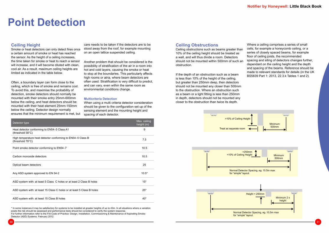
Ceiling ObstructionsCeiling obstructions such as beams greater than 10% of the ceiling height should be treated as a wall, and will thus divide a room. Detectors should not be mounted within 500mm of such an obstruction.
If the depth of an obstruction such as a beam is less than 10% of the height of the ceiling, but greater than 250mm deep, then detectors should not be mounted any closer than 500mm to the obstruction. Where an obstruction such as a beam or a light fitting is less than 250mm in depth, detectors should not be mounted any closer to the obstruction than twice its depth.
Where a ceiling comprises a series of small cells, for example a honeycomb ceiling, or a series of closely spaced beams, for example floor of ceiling joists, the recommended spacing and siting of detectors changes further, dependant on the ceiling height and the depth and spacing of the beams. Reference should be made to relevant standards for details (in the UK BS5839 Part 1: 2013, 22.3.k Tables 1 and 2).
Minimum500mm
Minimum500mm
Minimum 2 xheight
>250mm<10% of Ceiling Height
>10% of Ceiling Height
Height < 250mm
Normal Detector Spacing, eg. 10.5m maxfor “simple” layout.
Normal Detector Spacing, eg. 10.5m maxfor “simple” layout.
Treat as separate room
Point Detection
Ceiling Height Smoke or heat detectors can only detect fires once a certain amount of smoke or heat has reached the sensor. As the height of a ceiling increases, the time taken for smoke or heat to reach a sensor will increase, and it will become diluted with clean, cool air. As a result, maximum ceiling heights are limited as indicated in the table below.
Often, a boundary layer can form close to the ceiling, which is free of smoke and remains cool. To avoid this, and maximise the probability of detection, smoke detectors should normally be mounted with their smoke entry 25mm-600mm below the ceiling, and heat detectors should be mounted with their heat element 25mm-150mm below the ceiling. Detector design normally ensures that the minimum requirement is met, but
care needs to be taken if the detectors are to be stood away from the roof, for example mounting on an open lattice suspended ceiling.
Another problem that should be considered is the possibility of stratification of the air in a room into hot and cold layers, causing the smoke or heat to stop at the boundaries. This particularly affects high rooms or atria, where beam detectors are often used. Stratification is very difficult to predict, and can vary, even within the same room as environmental conditions change.
Multicriteria DetectionWhen using a multi criteria detector consideration should be given to the configuration set up of the sensing element and the mounting height and spacing of each detector.
Detector type Max. ceiling height (m)
Heat detector conforming to EN54–5 Class A1 (threshold 58°C)
9
High temperature heat detector conforming to EN54–5 Class B (threshold 78°C) 7.5
Point smoke detector conforming to EN54–7 10.5
Carbon monoxide detectors 10.5
Optical beam detectors 25
Any ASD system approved to EN 54-2 10.5*
ASD system with: at least 5 Class C holes or at least 2 Class B holes 15*
ASD system with: at least 15 Class C holes or at least 5 Class B holes 25*
ASD system with: at least 15 Class B holes 40*
* In some instances it may be satisfactory for systems to be installed at greater heights of up to 43m. In all situations where a variation exists the risk should be assessed and performance tests should be considered to verify the system response.For further information refer to the FIA Code of Practice: Design, Installation, Commissioning & Maintenance of Aspirating Smoke Detector (ASD) Systems. February 2012.
Notifier by Honeywell: Little Black Book

32 33
Partitions and RackingWhere the gap between the top of a partition or section of racking and the ceiling is greater than 300mm, it may be ignored. If the gap is less than 300mm it should be treated as a wall.
To maintain a free flow of smoke and heat to the detector, a clear space should be maintained for 500mm in all directions below the detector.
>300mm : No effect<300mm :Treat as wall
Minimum500mmClear
aPr
noitit
Racking /Shelving
Point Detection
Sloping CeilingsWhere the ceiling is pitched or sloping, the slope of the roof tends to speed the rise of smoke or heat to the apex, hence reducing the delay before the detectors are triggered.
For sloped roofs with a pitch height greater than 600mm for smoke detectors, or 150mm for heat detectors, a row of detectors should be placed within a maximum vertical distance of 600mm or 150mm for smoke or heat detectors respectively from the roof apex.
Sloped roofs rising less than 600mm for smoke detectors or 150mm for heat detectors may be treated as a flat ceiling.
Since the smoke or heat tends to rise faster up the slope, it is permissible to use a greater spacing for the row of detectors mounted in the apex of the roof: For each degree of slope of the roof, the spacing may be increased by 1% up to a maximum of 25%.
Where, the roof slopes are unequal the spacing down the slopes can be unequal, however along the roof apex spacing the lesser of the two figures should be used, in this example 10.5m +18%.
Where the slope finishes within the adjusted detection radius, the standard distance to the next row of detectors, 10.5m, should be used. Care must be taken when placing the next row that no gaps are left in detection coverage.
18°
15mMax 600mm
10.5
m
12.3
9m%81
+5.01 =
7.5m
8.85m
=7.5
+ 18%
9.35m
= 7.5
+ 25%
40°
Notifier by Honeywell: Little Black Book
34 35
Point Detection
Stairwells and Lift ShaftsInternal stairwells and lift shafts and other vertical service ducts through a building provide a clear path for smoke to pass between floors of a building as if they were chimneys. It is therefore important to protect these, preferably using smoke detectors.
All vertical shafts through a building must be protected by a smoke or heat detector at the top of the shaft, and by a detector within 1.5m of each opening onto the shaft.
In internal stairways, a detector should be mounted on each main landing. In addition, if the detectors on the landings are separated by more than 10.5m, intermediate detectors should be mounted on the underside of the stairs.
Detectors should also be fitted into any room opening directly onto a stairway other than a WC cubicle.
Clause 8.2f, recommends that for Categories L1 and P1, rooms such as toilets and bathrooms, lobbies to toilets and stairways, need not be protected if they are low fire risk. However, for category L3, L2 and L1, rooms opening onto the escape routes should have protection.
Care should be taken when interpreting this section, as if the toilet area is considered high risk, then detection should be provided, but the lobby being low risk would not need protection. However, if the toilet is deemed low risk and no detection is provided, to comply with covering rooms leading onto an escape route, then the lobby would require protection.
< 10
.5M
1.5M1.5M
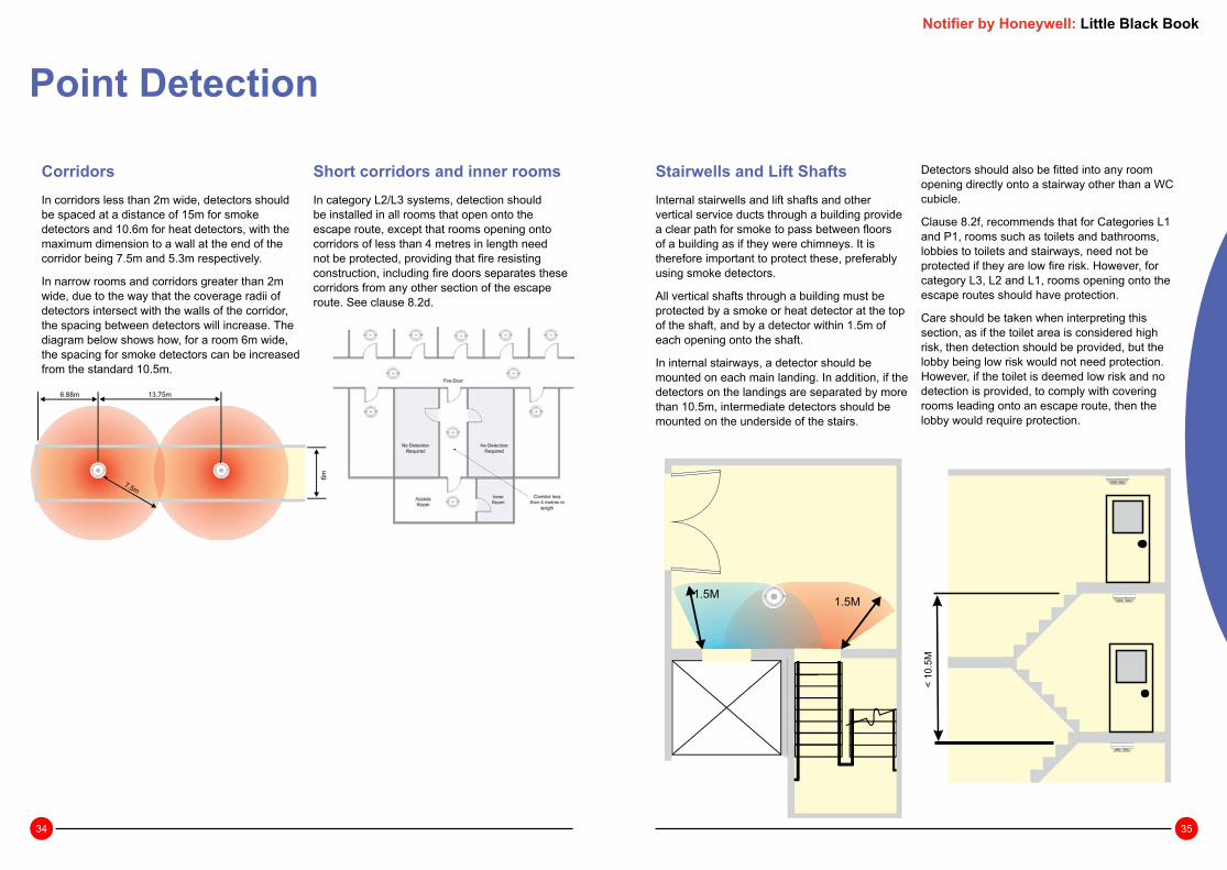
CorridorsIn corridors less than 2m wide, detectors should be spaced at a distance of 15m for smoke detectors and 10.6m for heat detectors, with the maximum dimension to a wall at the end of the corridor being 7.5m and 5.3m respectively.
In narrow rooms and corridors greater than 2m wide, due to the way that the coverage radii of detectors intersect with the walls of the corridor, the spacing between detectors will increase. The diagram below shows how, for a room 6m wide, the spacing for smoke detectors can be increased from the standard 10.5m.
Short corridors and inner roomsIn category L2/L3 systems, detection should be installed in all rooms that open onto the escape route, except that rooms opening onto corridors of less than 4 metres in length need not be protected, providing that fire resisting construction, including fire doors separates these corridors from any other section of the escape route. See clause 8.2d.
6.88m 13.75m
7.5m
6m
Notifier by Honeywell: Little Black Book

36 37
Voids and False CeilingsDetectors need not normally be installed in voids less than 800mm deep, unless on the basis of a fire risk assessment it is thought that fire or smoke could spread extensively through the voids before detection, or unless the fire risk in the void is such as to warrant protection. Use of heat and smoke detectors in voids greater than 800mm high is dependant on the protection category, and fire risk assessment.
Where they are installed into voids, a detector’s sensing element should be mounted either in the top 10% or the top 125mm of the void space whichever is greater. Although it can be difficult to install detectors the correct way up in void spaces, care should be taken as incorrect orientation of a detector can lead to increased ingress of dirt and dust, leading to reduced maintenance intervals, and possible nuisance alarms.
Detectors above a false ceiling may be used to protect the area below it, if the false ceiling is perforated uniformly across the complete area of the ceiling, with the holes making up over 40% of the ceiling surface area, having a minimum size of 10mm and the false ceiling having a thickness of less than three times the dimensions of the perforations.
In all other cases, the areas above and below a false ceiling should be treated as separate, and thus should be protected separately with detectors below the ceiling, and if necessary in the void above the ceiling.
Lantern LightsA detector should be mounted in any lantern light used for ventilation or having a height exceeding 800mm. The temperature in lantern lights can change rapidly owing to heating by sunlight, which means that rate-of-rise heat detectors should not be used and heat detectors should be protected from direct sunlight.
Ceilings with other obstructions or Air Handling unitsOne of the most common mistakes is to mount a smoke sensor adjacent to the air conditioning intake or outlet grill. The minimum distance between the two should be at least 1 metre and further if possible.
This is due to the fact that smoke may have difficulty penetrating the sensor when the air conditioning is switched on. Also there is a greater risk of the sensor becoming contaminated and giving rise to false alarms.
Notifier by Honeywell: Little Black Book
Point DetectionProduct Range at a Glance
Part Number
OPAL Optical smoke detector NFXI-OPT
OPAL Heat detector, fixed 58ºC NFXI-TFIX58
OPAL Heat detector (A1R), rate of rise + fixed 58ºC NFXI-TDIFF
OPAL Heat detector, fixed 78ºC NFXI-TFIX78
OPAL SMART2 Optical smoke & heat detector NFXI-SMT2
OPAL SMART3 Optical smoke & heat detector with infra-red flame sensing NFXI-SMT3
SMART4 Infrared, Carbon Monoxide, Optical, Thermal Multisensor IRX-751CTEM-IV
VIEW™ high sensitivity analogue addressable laser smoke sensor with twin LED’s, insect resistant screen, removable cover for field cleaning, direct decade 01-99 address entry, LED output and device blink option.
FSL-751E US
Analogue sensor base with SEMS screw connections and address identification label B501AP
White deep analogue sensor base with built in relay, with SEMS screw connections and address identification number B524RTE-W

38 39
High Sensitivity Laser Point DetectionThe high sensitivity LASER detector is wired on a standard fire alarm system loop and is similar to a normal point detector in appearance but internally it is very different. The standard LED found in a normal optical detector is replaced by a LASER Diode which is aimed at a optical amplifier which is in fact a cylindrical mirror. The LASER diode has the advantage of not picking up stray signals from dust within the chamber. This, combined with co-operation detection where the control panel takes data from groups of sensors and makes a collective decision.
This method of point detection delivers uniquely high sensitivity smoke detection of up to 0.07% obs./mtr. This level of sensitivity is comparable to EN54-20 Class A Aspirating Systems and provides fast response to incipient fires combined with good nuisance alarm rejection.
Notifier by Honeywell: Little Black Book

40 41
Very Intelligent Early WarningThree components make up the VIEW LASER point detection system, the intelligent control panel, VIEW laser sensors and the Advanced Signal Processing Software. All work together to ignore unwanted signals caused by dust, electrical and electromagnetic interference whilst delivering sensitivity up to 0.07% obs./mtr without moving parts, pipes, fans or dust filters.
The system pinpoints the fire location and provides controlled stability, automatic drift compensation and adjustable alarm and pre-alarm settings. When placed within a cabinet the sensitivity levels of 0.07% would detect an overheated resistor.
LASER point detectors pass all test laid down in BS6266 (Hot Wire Test) and can be classed as a high sensitivity smoke detector in line with EN54 part 20 Class A.
Co-Operating SensorsPoint detection has a unique process called co-operation detection. Sensors within a similar area are grouped together and the fire alarm control panel then takes data from these grouped sensors and makes a collective decision.
This method of detection also provides faster response as well as good unwanted alarm deterrent.
Dynamic Intelligent Grouping The dynamics of this process is a rota that is continually updated with the five highest analogue values.
There is a prequalification to get into the Dynamic Group which is 30% of the standalone threshold levels and as these levels change the detectors are removed from this pool and replaced with the next highest value. This ensures that the co-operating algorithms are at their best at all times.
The 5 highest analogue values join the Dynamic Intelligent Group which is continually updated. The joining threshold is 30% of the standalone alarm value.
Laser Point Detection
Time (minutes) )
Sm
oke
Obs
cura
tion
(% p
er m
etre
)
Multi DetectorSensing Alarm
SingleSensorAlarm
Time Savings
Sensor C
Sensor B
Sensor A
CombinedSignal
Sensor A Alarm Level
30% (variable due to air quality)
Sensitivity AdjustmentThere are 9 Alarm levels and 8 Pre-Alarm levels plus a Self Optimising Level. These can be independently set per detector and adjusted on a time base from the control panel. The self Optimising level is best suited to very high sensitivity levels and has to be conducted over a 2 week soak testing period.
Pre Alarms - the ability to set thresholds at high sensitivities to give local audible and visual indication of impending alarms.
Alarm Levels - need to be configured in conjunction with the environment, i.e. if set to low would cause a nuisance value.
System ConnectionAspirating systems have to be linked to the fire system via interfaces and require a 24V supply to operate. If these links are broken or the PSU fails then the system is lost and the room may not be covered or be able to activate the main control panel.
Laser detectors form part of the loop, do not require a separate supply and have critical path redundancy ensuring that the room is covered at all times. The sensitivity and reporting are all done at the control panel. Full addressability means the precise location of where the alarm has occurred can be identified.
Alarm 9 (3.24%)
Alarm 8
Alarm 7 (1.63%)
Alarm 6
Alarm 5 (0.98%)
Alarm 4
Alarm 3 (0.33%)
Alarm 2
Alarm 1 (0.1%)
Pre-alarm 9 (1.63%)
Pre-alarm 8Pre-alarm 7
Pre-alarm 6
Pre-alarm 5 (0.33%)
Pre-alarm 4Pre-alarm 3 (0.1%)Pre-alarm 2 (0.07%)Self Optimising
Sm
oke
Obs
cura
tion
(% P
er M
etre
)
24V
PS
U
Server Room
Notifier by Honeywell: Little Black Book

42 43
Laser Point DetectionSystem DesignBoth air sampling holes and detector spacing’s are the same and in accordance with BS5839 and BS6266 for both ASD and Laser Detectors.
However, unlike ASD systems where the sensitivity of a each sampling point varies depending on how many sampling holes are used, each laser detector has a maximum sensitivity of 0.07% obs/mtr.
Laser Detection and hole spacing on ASD systems can be designed to cover 100M2 as per standard optical detector. However, due to the general environment in which these products are found air velocity and change need to be considered and detector spacing will need further design input in line with BS6266.
The faster or greater the air change the higher the sensitivity of the detection system as the more velocity the more dilution of smoke. As a result, more detectors (or sampling holes for ASD systems) are required. A detection system that is more sensitive will detect smaller amounts of smoke quicker than a less sensitive detector that has a faster response.
If no local standards are applicable (e.g. BS 6266) the recommended coverage per sensor is 40 square metres. For very high air flow applications (over 10 air changes/hour), the recommendation is 25 square metres per sensor. This information is required in advance of design.
Standard detector spacing BS5839 Pt 1
Area of coverage=100m2
Laser detector spacing BS6266 High Air Flow
Area of coverage=25m2
Typical coverage with an airflow at greater than 10 changes per hr 25m². Note detectors are spaced so that the corners of the room are also protected.
Typical coverage with an airflow less than 10 changes per hr at 40m² increased coverage. Note detectors are spaced so that the corners of the room are also protected.
6.3 m
6.3 m
Area = 40 sq. m
(6.3 x 6.3m)
4.45 m
3.15 m
5 m
5 m
Area = 25 sq. m
(5 x 5 m)
3.5 m
2.5 m
Notifier by Honeywell: Little Black Book

44 45
Notifier by Honeywell: Little Black Book
Beam DetectionThis section aims to help the fire alarm system designer gain an understanding of the beam smoke detector’s capabilities and limitations, and how they differ from point detectors.
Please note that this document is intended only as a general guide to the application of beam detectors. Reference should always be made to the detector manufacturer’s installation requirements and instructions, and to BS5839 part 1.
Beam smoke detectors can be important components of a well-designed automatic fire alarm system. Their unique capabilities enable beam smoke detectors to overcome many of the problems and limitations of point detectors in some applications.
Notifier by Honeywell: Little Black Book

46 47
Principles of OperationThere are two basic types of projected light beam detectors, both of which operate on the principle of light obscuration: a light beam is projected across the area to be protected, and is monitored for obscuration due to smoke
An End-to-End type detector has separate transmitter and receiver units, mounted at either end of the area to be protected. A beam of infrared light is projected from the transmitter towards the receiver, and the signal strength received is monitored.
Reflective or Single-Ended type detectors have all the electronics, including the transmitter and receiver mounted in the same housing. The beam is transmitted towards a specially designed reflector and the receiver monitors the attenuation of the returned signal.
Unlike point type optical smoke detectors, the response of beam smoke detectors is generally less sensitive to the type and colour of smoke. Therefore, a beam smoke detector may be well suited to applications unsuitable for point optical smoke detectors, such as applications where the anticipated fire would produce black smoke. Beam smoke detectors do however require visible smoke.
The total obscuration of the light beam will normally be seen as a fault condition, rather than an alarm. This minimizes the possibility of an unwanted alarm due to the blockage of the beam by a solid object, such as a sign or ladder.
Very small, slow changes in the quality of the light source due to dust and dirt accumulation are not typical of a smoke signature. These changes are typically compensated for by automatic drift compensation. The rate of compensation is limited to insure that the detector will still be sensitive to slow or smouldering fires.
Beam DetectionNotifier by Honeywell: Little Black Book
AccessoriesAccessories to the beam smoke detector may include remote annunciators, remote test stations which allow for the periodic electronic testing of the detector, and filters used as a “go / no go” test of the detector’s proper calibration.
Proper ApplicationLike point smoke detectors, beam smoke detectors are inappropriate for outdoor applications. Environmental conditions such as temperature extremes, rain, snow, sleet, fog, and dew can interfere with the proper operation of the detector and cause nuisance alarms. In addition, outdoor conditions make smoke behaviour impossible to predict and thus will affect the detector’s response to a fire.

48 49
Comparisons Between Beam Detectors and Point DetectorsIt is important that the fire system designer understands and gives full consideration to the differences in the principles of operation of point and beam smoke detectors.
CoverageAccording to BS5839 part 1, a point smoke detector has a maximum radius of coverage of 7.5m. For a simple spacing plan as demonstrated opposite, this translates to a maximum distance
between detectors of 10.5m. Careful manipulation of the detector layout, can reduce the number of point detectors required to cover a given area, however to cover large areas, many point detectors will be required.
For beam smoke detectors, BS5839 part 1 allows a maximum range of 100m, and coverage of 7.5m either side of the beam, thus giving theoretical area coverage of 1500m² an area which normally would require sixteen or more point smoke detectors to cover. Reducing the number of devices used will lower installation and maintenance costs.
Point detector coverage over beam detector maximum area.
Maximum Area Coverage for Beam Detectors
Notifier by Honeywell: Little Black Book
Beam Detection
Ceiling HeightAs a smoke plume rises, it spreads and becomes diluted. Point detectors tend to become less sensitive the higher they are mounted. BS5839 part 1 thus limits the mounting height of point detectors for life protection to 10.5m, or 15m for property protection.
Beam smoke detectors are ideally suited to high ceiling applications since they can sample across the entire smoke plume. BS5839 part 1 permits the use of beam detectors up to heights of 25m for life protection (type L), and 40m for property protection (type P).
In some applications, especially where high ceilings are present, beam smoke detectors may be more responsive to slow or smouldering fires than point detectors because they are looking across the entire smoke field intersecting the beam. Point detectors can only sample smoke at their particular “spot”. The smoke that enters the chamber may be diluted below the alarm threshold (level of smoke needed for an alarm).
The major limitation of the projected beam smoke detector is that it is a line-of-sight device and is therefore subject to interference from any object or person, which might enter the beam path. This makes its use impractical in most occupied areas with normal ceiling heights.
Many facilities have areas where beam smoke detectors are the detector of choice. High ceiling areas such as atriums, lobbies, gymnasiums, sports arenas, museums, church sanctuaries, as well as factories and warehouses are good examples. Many of these applications present special problems for the installation and maintenance of point detectors. Using beam detectors may reduce these problems since fewer devices may be required, and the devices can be mounted on walls, which are more accessible than ceilings.

50 51
Beam Detection
High Air VelocityHigh air movement areas present a special problem for detecting smoke for both point and beam smoke detectors because the propagation of smoke developing under normal conditions may not occur. High air velocity may blow smoke out of the sensing chamber of a point detector. Careful consideration should be given to the point detector’s performance where air velocities exceed 1.5 metres per second, or when air changes in the protected area exceed 7.5 changes per hour.
A beam smoke detector’s sensing range can be as long as 100m, rather than the 50mm dimension of a point detector’s sensing chamber. It is therefore less likely that smoke will be blown out of the beam smoke detector’s sensing range.
Although reduced spacing is not required in high airflow areas, attention should be given to the anticipated behaviour of smoke in these applications.
StratificationStratification occurs when the air within a room forms into layers at different temperatures; for example, the area just beneath an atria roof may be heated by sunlight, and create a layer of hot air above the main volume of the room. Smoke is heated by the fire, and rises though cooler lower layers until it reaches the warmer layer, will not rise any further and will spread along the hot / cold boundary, rather than the ceiling, possibly never reaching detectors mounted on or near the ceiling. Normally on smooth ceilings, beam smoke detectors should be mounted between 300 and 600 millimetres from the ceiling. However, the final location and sensitivity of the detectors should be subject to an engineering evaluation which is beyond the scope of this guide, but which will typically include structural features, the size and shape of the room and bays, occupancy and uses of the area, ceiling height, ceiling shape, surface and obstructions, ventilation, ambient environment, burning characteristics of the combustible materials present, and the configuration of the contents in the area to be protected.
Effect of Stratification Reflective Beam Detector Operating though a Window.
Notifier by Honeywell: Little Black Book
Hostile EnvironmentsOne limitation of point smoke detectors is their vulnerability to hostile environments, such as extremes of temperature, dirt, humidity, and corrosive gases.
Beam smoke detectors may also be subject to some of these debilitating elements. While it is generally not recommended, a beam smoke detector can, be placed behind clear glass windows outside the hazard, in order to overcome these effects. This feature may also allow them to be used in applications where explosion protection is required.
Barns and stables housing animals are good examples where early warning is required but where point smoke detectors may be unsuitable because of temperature extremes and dusty, dirty conditions. Beam smoke detectors offer an alternative because their optics can be kept behind windows that are easily cleaned on a regular basis. They may also have a much wider operating temperature range than point smoke detectors.
However restrictions do apply: the glass must be kept clean and free of obstructions, and in the case of reflective type detectors, the beam must be placed at an angle to the window to prevent reflections from the glass causing incorrect signals. Consideration also needs to be made to the reduction in signal due to losses as the beam passes through the window. It may be necessary to reduce the maximum allowable beam length by up to 20% for a reflective type beam detector.

52 53
ObstructionsObstructions on or near the ceiling or on the walls of a protected area will affect smoke distribution, and thus need to be taken into consideration during the fire protection system design.
Ceiling obstructions such as joists greater than 10% of the total room height should be treated as a wall, and thus the areas on either side should be treated as separate rooms. Similarly, if partitioning or racking is closer than 300mm to the ceiling they offer a significant obstruction to the distributions of smoke and should be treated as walls.
For rooms with a number of joists or structural beams, the detector beam should be run parallel with the joists. Depending on the depth of the joists, the area that the detector can protect either side of its beam may be affected.
Beam detectors should not be mounted so their optical beam runs any closer than 500mm to any wall or obstruction such as ducting or structural beam. Some types of beam detector use a wide beam, and these may require a greater spacing than 500mm from any obstructions.
Obstructions will inhibit the free flow of smoke within a room and thus affect the detectors ability to detect a fire. When an obstruction is reflective, spurious signals may be reflected back to the receiver and distort the detector’s response. This can lead to nuisance alarms or the detector failing to detect a fire. Therefore, all reflective surfaces should be a minimum distance (e.g. for Notifier Opal beam detectors - 380mm) from the centre line of the detector beam. In fact, it is good practice to ensure that the spacing from the beam centre line is applied to all objects.
Beam BlockageOptical beam detectors are line of sight devices, and rely on a clear path between the transmitter and receiver or reflector. If the beam is blocked, then the detector cannot detect a fire. Care must therefore be taken that the beam is not mounted where it could become blocked during normal operation. If people are likely to be present in the protected area, then the detector should be mounted a minimum of 2.7m above floor level. Other possible causes of beam blockage including forklift operation for example should also be considered.
Supplementary DetectionIn areas with relatively high ceilings, for example an atrium, supplementary beam detectors can be used to provide earlier warning of a fire, or to help guard against the effects of stratification. However since they are not subject to the spreading effect of a ceiling on a plume of smoke, the beam spacing should be reduced. BS5839 part 1 recommends that supplementary beam detector cover should be 12.5% of the height of the beam above the highest likely seat of a fire to either side of the detector beam.
Beam DetectionNotifier by Honeywell: Little Black Book
Design RequirementsMany factors affect the performance of smoke detectors of all types. The type and amount of combustibles, the rate of fire growth, the proximity of the detector to the fire, and ventilation factors are all important considerations. European approved beam smoke detectors are tested to EN54-12: 2002 Fire Detection and Fire Alarm Systems - Smoke Detectors - Line Detectors using an optical light beam. They should be installed and maintained in accordance with the manufacturers requirements and in the UK BS5839 part 1: 2013.
SensitivityThe detector’s sensitivity should be set with reference to the length of the beam used on a given application, combined with the environmental conditions at that location.
Location & SpacingThe following recommendations are based on BS5839 part 1: 2013. On a flat, unobstructed ceiling, the maximum distance covered by a beam detector should be 100m, or as per the manufacturers recommendations if they are less. No point in the protected area should be more than 7.5m from the centre line of the detector beam. This gives a maximum spacing between two beam detectors of 15m, and a maximum distance from a wall to a beam detector of 7.5m.
Due to the large area it is possible to protect using a single beam detector, care needs to be taken that search distance requirements are not exceeded. BS5839 part 1 recommends that the maximum distance travelled to visually locate a fire within a fire zone should be 60m. Where a beam detector is used to protect for example a large warehouse with racking and partitioning, it would be easy to exceed this requirement.
Pitched RoofsWhen a roof is pitched, smoke tends to roll quickly up the slope of the roof, and collect into the apex. Therefore, if a detector is to be mounted on a pitched ceiling, having a rise height of greater than 600mm, a detector should be mounted at or within 600mm of the apex of the roof. Where the sloped area of the roof is long enough, the distance from the detector at the apex of the roof to the next may be increased from 7.5m at a rate of 1% per degree of slope, up to a maximum of 25%. If the rise is less than 600mm the slope should be ignored and the roof treated as flat. Note that this increased coverage applies only to detectors fitted at the apex of the roof; standard spacing applies to all other detectors.
For example, up to18.75m width can be covered by one optical beam detector mounted within 600mm vertical of the apex, using the extra coverage of 25% given by a roof angle of 25 degrees.

54 55
Building MovementsOne of the major considerations when siting beam detectors is the effect of the movement of the building as it is subjected to various environmental forces. Wind, snow, rain and temperature can all cause a building to flex. Over longer ranges, even slight deformations of the mounting structure can cause the beam to move considerably from its target - over a 100m range, a movement of 0.5° at the transmitter will cause the centre point of the beam to move nearly 900mm.
In order to minimise possible false alarms or fault signals caused by building movement, the beam detector must be mounted on solid parts of the building such as the main support pillars. They should never be mounted on easily deformed sections such as metallic cladding. If it is not possible to mount both components of the detector onto solid construction, then the transmitter should be fixed to the more solid surface, since movement will affect the receiver or reflector less than the transmitter.
Beam DetectionNotifier by Honeywell: Little Black Book
Effect of Detector Movement
Testing and MaintenanceAs dust builds upon a beam detector’s optical components, its sensitivity will increase leading to an increased susceptibility to nuisance alarms. Most modern beam detectors include algorithms to compensate for this gradual build up of dirt and reduce maintenance whilst retaining constant sensitivity, however, the detector lenses and reflector will still need periodically to be cleaned. The maintenance interval will be dependant on site conditions.
MaintenanceManufacturer’s instructions should be referred to for cleaning procedures, however a fairly typical maintenance method is to clean the detector lenses and reflector with a damp soft cloth and a mild soap. Solvents should not normally be used.
Note: Before carrying out any maintenance on the detector, notify the relevant authorities that the fire detection system is undergoing maintenance, and that the system is therefore temporarily out of service. Disable the relevant zone to prevent unwanted alarms.
Functional TestingFollowing installation, or any routine maintenance work, beam detectors should undergo functional testing. The normal means of testing a beam detector is to place a filter in the path of the beam to reduce the amount of received light below the detector threshold and thus produce an alarm.
With the Notifier Opal Beam detector, a graduated scale is marked on the reflector. To test the sensitivity, a suitable piece of opaque material is used to block off a section of the reflector corresponding to the sensitivity, checking that the detector reacts as expected.
The Notifier Opal Beam detector also incorporates an automatic test feature. On command from a remote station, a calibrated filter is moved in front of the receiver, simulating the effect of smoke on the beam. If the correct signal reduction is detected then the detector will enter the alarm condition, otherwise a fault is returned. This function meets the periodic maintenance and testing requirements of most local standards providing a complete check of every component in the alarm path without the need for access at high level.
Notifier Opal Beam Detector remote test operation

56 57
Product Range at a Glance
Part NumberLoop powered reflective IR beam, complete with reflector for up to 70 metres. Use BEAM-LRK for 70 to 100 metres.
NFXI-BEAM
Loop powered reflective IR beam with servo test feature, com-plete with reflector for up to 70 metres. Use BEAM-LRK for 70 to 100 metres.
NFXI-BEAM-T
Surface Mount Kit for IR reflective beam. Allows direct surface cable entry. 6500-SMK
Multi Mount Kit for IR reflective beam. Provides ceiling and wall mount swivel bracket. Note : requires BEAM-SMK. 6500-MMK
Long range reflector kit for 70 to 100 metres. BEAMLRK
Remote test key switch for beam detectors 6500RTS-KEY
Heater kit for beam unit BEAMHK
Heater kit for reflector unit BEAMHKR
Notifier by Honeywell: Little Black Book
Beam Detection

58 59
Legislation & Codes of Practice
• EN 54 part 20 Fire detection and fire alarm systems. Aspirating smoke detector
• BS EN 5839 Part 1 2013 Design, Installation, Commissioning and Maintenance fire detection and alarm systems
• BS6266 - Fire protection for electronic equipment installations
• FIA Code of Practice: Design, Installation, Commissioning & Maintenance of Aspirating Smoke Detector (ASD) Systems. February 2012.
Air Sampling (Aspirating)Smoke DetectionASD (or Aspiration Smoke Detection) systems draw air samples continuously from the monitored area through a pipe system fitted with sampling holes at regular intervals. The sampled air is then analysed for smoke particles and an alarm is raised if smoke is present. The system is active, continually drawing air samples from the monitored area.
Some aspirating systems can now be remotely monitored through IP connectivity, maximising the benefits of this very early warning capability in reacting to an incident.
Notifier by Honeywell: Little Black Book

60 61
High Sensitivity ASD systemsAspirating Smoke Detection (ASD) systems can detect fires at a very early stage, often before visible smouldering takes place, before an open fire occurs and before intense smoke develops. This early detection is vital to mission critical and high-risk applications such as EDP areas, Internet data centres and network operating centres. Such areas typically have an increased fire risk due to high power requirement and density of equipment. The earliest possible fire detection brings significant time benefits, enabling a fast response to the first signs of smoke.
EN54-20 Sensitivity ClassesSmoke detector sensitivity is normally defined in terms of ‘percentage obscuration per metre’ (%obs./mtr) - that is to say, the amount of smoke required to obscure the passage of light by a given percentage across a distance of one metre.
The EN54 Part 20 Code of Practice defines three sensitivity categories for smoke detection systems:
Class A Very High Sensitivity, used where very early warning fire detection is required. Designed primarily for high-risk areas and where high levels of air conditioning and air dilution exist.
Class B Enhanced Sensitivity, very early fire detection for most areas in which valuable goods and/or processes need to be protected.
Class C Normal Sensitivity, for general fire protection applications.
Approaches to achieve EN54 Part 20 Class A SensitivityAir Sampling Detection ASD systems draw air samples continuously from the monitored area through a pipe system fitted with sampling holes at regular intervals. The sampled air is then analysed for smoke particles and an alarm is raised if smoke is present and reaches the pre-determined smoke concentration level.
Laser Point DetectionAn alternative technology to deliver high sensitivity smoke detection is offered by certain laser point detection systems. Such devices can be wired on a standard fire alarm system loop and is similar to a normal point detector in appearance but internally it is very different. The standard LED found in a normal optical detector is replaced by a LASER Diode. This, combined with co-operation detection where the control panel takes data from groups of sensors and makes a collective decision delivers detection sensitivity of up to 0.07% obs./mtr.
This level of sensitivity is comparable to EN54-20 Class A ASD systems and provides fast response to incipient fires combined with good nuisance alarm rejection.
For more information please refer to the “Laser Point Detection” chapter found earlier in this guide.
Notifier by Honeywell: Little Black Book
Air Sampling Detection
ASD System ApplicationsTo protect people, mission critical facilities and high value assets from the faintest traces of smoke, in a wide range of challenging environments.
Mission CriticalFor these environments, there is no downtime. Every second lost, every transaction missed, any data or equipment destroyed can mean huge financial losses. High sensitivity aspirating systems alert facility managers hours, even days before the first indication of system trouble – helping them keep their mission critical facilities up and running 24/7 and preventing unnecessary activation of suppression systems.
Discrete DetectionWhen aesthetics matter, such as in museums, churches or mansions, an aspirating system provides a discrete smoke detection solution that is nearly invisible to the public. At the same time, it provides the earliest and most accurate smoke detection available to protect high-value items from fire.
Restricted AccessSome fire systems must protect areas such as prisons and public spaces, where there is a concern for tampering. An aspirating system can be mounted in a secure area while air sampling points are located in the protected environment minimising the potential for tampering.
Difficult EnvironmentsSome areas, like cold storage facilities, high bay warehousing or wash down areas (food preparation) have environmental conditions outside the tolerance of typical fire detection technologies. Aspirating units can be mounted at an accessible location at low level or, where access is an issue, out side of the protected area while sampling points can be located within the environment, enabling ease of maintenance.
Data and Remote ConnectivityThe FAAST system from Notifier provides you with the data you need to manage your environment. It includes 5 alarm levels, 10 pre-alarm particulate levels and a 10-level airflow pendulum which verifies that air is flowing effectively through the pipe network. It also includes a full range of fault indications. All of this information can be read quickly and easily on the device’s intuitive integral display or through a variety of remote devices.
If there is a situation at your facility, you need to know about it instantly. FAAST’s unique onboard Ethernet interface enables you to monitor the detector from any Internet browser, smart phone or mobile device with VPN capability. You can also configure the detector to deliver e-mail status updates to appropriate personnel. This means you will be advised of whatever you need to know to protect your facility.

62 63
Air Sampling DetectionMonitored AreaThe sampling holes in the monitored area are arranged so that the same amount of air is drawn through each hole. Each sampling hole is therefore allocated the same monitored coverage as a point-type smoke detector.
Cumulative EffectA cumulative effect is achieved by having multiple sampling holes in a room. Each sample hole will take in small samples of smoke as it spreads across the protected area. This cumulative smoke is therefore delivered to the detector as the sum of each of the sample holes within the risk.
This enables the ASD system to give a much earlier indication of a developing fire at the incipient stage. High false alarm immunity The physical separation of the detection unit from the monitoring area reduces the risk of transient faults such as those caused by condensation and electromagnetic radiation. The use of filters and the appropriate signal processing also guarantee reliable detection in dusty conditions.
Maximum CoverageThe maximum coverage of an ASD system is determined by the number of point-type detectors than can be replaced by an ASD device. This is a crucial factor in determining what savings can be made by installing an air sampling system. The coverage can be worked out simply by calculating how many sampling holes can be installed at a reasonable distance from each other (that of a point detector).
British StandardsIn addition to EN54-20, ASD systems should be designed and installed in accordance with the FIA Code of Practice, BS5839-1 20013 and BS6266 2011 where relevant.
BS5839-1 - Used when the design mimics that of standard detection. ASD systems are used to directly replace point or other conventional detection methods for practical, environmental and/or financial reasons.
BS6266 - Used when installing ASD systems with Electrical Equipment such as IT/Communication suites. Again, design mimics that of traditional detection, however the use of high sensitivity systems are encouraged and in some cases demanded.
Notifier by Honeywell: Little Black Book
Designing EN54-20 Compliant SystemsIf an ASD device has been correctly classified as Class A, B or C, this does not necessarily mean that it will satisfy the class specified in the project design. Labelling a device with a detection class simply indicates that a minimum project design with a single sampling hole corresponding to the specified class can be implemented. It is therefore important to check that the entire project design satisfies the desired detection class.
This can be done by the use of software supplied by ASD system manufacturers. The software takes into account the configuration options within the scope of the defined project design limits. The software should produce a conformity declaration for the detection categories specified by the selected project design in accordance with EN54-20.

64 65
Expansion and ContractionExpansion or contraction of plastic pipe is caused by temperature change occurring within the pipe wall. When the operating temperature of a pipe is greater than when it was installed, then the pipe will expand. If the operating temperature is lower, then it will contract.
There are two factors to consider when calculating expansions or contractions in pipes.
1. Ambient temperature of the (air temp) environment when installing the pipe
2. Change of temperature of pipe contents or environment
Any change of the above factors will affect the mid-wall temperature of the pipe thus causing either expansion or contraction.
Please note that most pipe work systems are installed between 5ºC and 25ºC. Coefficient of Linear Expansion for Plastics
Calculating Expansion/Contraction
1. The change in length due to contraction or expansion in a pipe system is determined by the following formula:
ΔL = ΔT x L x □
Where ΔL Expansion (ΔLe) or contraction (ΔLc) in mm
ΔT Difference in temperature between the installation and the operating temperatures in ºC ( = T operate - T install)
L Length of pipe when installed
□ Relevant coefficient of expansion (ABS will expand 0.100mm per metre, for every 10ºC raised in mid-wall temp above the installation temperature)
Example:
Find the expansion and contraction on a 25mm diameter ABS pipe system, installed at 10ºC. The maximum and minimum operating temperatures are 30ºC and 8ºC respectively. The overall length of the installation is 30m.
Step 1) Calculate temperature change for expansion and contraction:
ΔT = 30 - 10 = +20ºC.
ΔT = 8 - 10 = -2ºC.
Step 2) Now calculate expansion & contraction,
Expansion:
ΔLe = ΔT x L x □ 20 x 30 x 0.100 = 60mm
Contraction:
ΔLc = ΔT x L x □ -2 x 30 x 0.100 = -6mm
Step 3) In order to provide for the correct solution, it is necessary to take the greater value, regardless whether it is due to expansion or contraction. i.e. ΔL = 60mm.
How to Allow for Expansion or ContractionThe change of length in a pipe system, whether it is expansion or contraction, will require compensation, so that any stresses generated by the change will not cause damage to the system, this can be done in by the use of an expansion loop, an expansion joint or using flexible arms.
1) Expansion Loops
These are designed to compensate for linear expansion or contraction within a pipe system. They are an ideal option when facing a large amount of movement due to expansion or contraction. For large amounts of movement we suggest you use the 100cm flexible connector; solvent weld one end to the pipe where you wish the expansion to be taken up and form a loop before solvent welding the other end to the pipe system
Air Sampling DetectionNotifier by Honeywell: Little Black Book
Pipe systemsABS Pressure Pipe SystemsABS (Acrylonitrile Butadiene Styrene) is a homog-enous material with good chemical resistance and high impact strength.
Other beneficial features are its suitability for use at low temperatures (-40ºC) and its ease of jointing.
StandardsIndividual products should be in accordance with the appropriate British Standards:
• Fittings (Metric) Din 8063, Kiwa 549, ISO 727
• Pipe BS 5391 EN 61386-1 Class 1131
• Adhesive BS 4346 Part 3
Technical - jointing guidelinesSolvent cement is specially formulated to chemi-cally weld pipes and fittings together. The solvent cement chemically melts the two surfaces to be joined, so that when they are fitted together they form a homogenous mass, which then cures to form a weld. Note that this is not a glued joint.
It is therefore important to choose the correct type of adhesive as another type may be detrimental to the integrity of the system.
1. Cut the pipe at right angles to its axis, and to the required length using the correct cutting shears.
2. Dry fit the pipe to the socket of the fittings. When the pipe is fully home in the socket, draw a line around the pipe at the edge of the socket. Where this is not possible (per-haps on larger fittings) measure the socket depth and draw a line at the corresponding point along the pipe. This will give a visual indication, to ensure that the pipe is fully pushed home in the socket.
3. Apply the solvent cement with a suitably sized brush or the brush provided in the adhesive lid. Ensure that the area of the pipe up to the visual indicator is completely covered with an even layer of cement. This part of the operation must be done quickly and neatly, as the solvent must still be wet when the pipe and fitting is pushed together.
4. Push the pipe and fittings together and hold in place for up to 30 seconds. When the joint is made, a bead of solvent cement will form around the outer joint of the pipe and socket. This excess cement should be wiped away leaving the outer part of the joint clean.
Jointing ‘Don’ts’
• Don’t make joints in rain or wet conditions
• Don’t use dirty brushes or cleaning rags, which are dirty or oily.
• Don’t use the same brushes with different solvent cements.
• Don’t dilute or thin solvent cements with cleaner.
• Don’t leave solvent cement tins open. The contents will evaporate and the cement performance will be weakened.
• Don’t use near naked lights, or smoke whilst jointing. Solvents are highly inflammable.
• Don’t make joints in a confined space. Solvents emit hazardous vapours, which are dangerous.
Joints per Litre of Cement
As a rule of thumb around 70 joints can be made per 250ml of solvent cement when jointing 25mm ABS fittings and pipe.
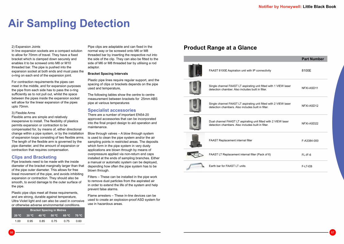
66 67
Notifier by Honeywell: Little Black Book
Air Sampling Detection
Product Range at a Glance
Part Number
FAAST 8100E Aspiration unit with IP connectivity 8100E
Single channel FAAST LT aspirating unit fitted with 1 VIEW laser detection chamber. Also includes built in filter. NFXI-ASD11
Single channel FAAST LT aspirating unit fitted with 2 VIEW laser detection chambers. Also includes built in filter. NFXI-ASD12
Dual channel FAAST LT aspirating unit fitted with 2 VIEW laser detection chambers. Also includes built in filter. NFXI-ASD22
FAAST Replacement internal filter F-A3384-000
FAAST LT Replacement internal filter (Pack of 6) FL-IF-6
Earth bar for FAAST LT units F-LT-EB
2) Expansion JointsIn line expansion sockets are a compact solution to allow for 70mm of travel. They have a fixed bracket which is clamped down securely and enables it to be screwed onto M8 or M10 threaded bar. The pipe is pushed into the expansion socket at both ends and must pass the o-ring on each end of the expansion joint.
For contraction requirements the pipes can meet in the middle, and for expansion purposes the pipe from each side has to pass the o-ring sufficiently as to not pull out, whilst the space between the pipes inside the expansion socket will allow for the linear expansion of the pipes upto 70mm.
3) Flexible ArmsFlexible arms are simple and relatively inexpensive to install. The flexibility of plastics permits expansion or contraction to be compensated for, by means of, either directional change within a pipe system, or by the installation of expansion loops consisting of two flexible arms. The length of the flexible arm is governed by the pipe diameter, and the amount of expansion or contraction that requires compensation.
Clips and BracketingPipe brackets need to be made with the inside diameter of the bracket marginally larger than that of the pipe outer diameter. This allows for free lineal movement of the pipe, and avoids inhibiting expansion or contraction. They should also be smooth, to avoid damage to the outer surface of the pipe.
Plastic pipe clips meet all these requirements, and are strong, durable against temperature, Ultra Violet light and can also be used in corrosive or otherwise adverse environmental conditions.
Pipe clips are adaptable and can fixed in the normal way or be screwed onto M6 or M8 threaded bar by inserting the respective nut into the side of the clip. They can also be fitted to the side of M6 or M8 threaded bar by utilising a rod adaptor.
Bracket Spacing Intervals
Plastic pipe lines require regular support, and the spacing of clips or brackets depends on the pipe used and temperature,
The following tables show the centre to centre measurement between brackets for 25mm ABS pipe at various temperatures
Specialist accessoriesThere are a number of important EN54-20 approved accessories that can be incorporated into the final project design to aid operation and maintenance.
Blow through valves – A blow through system is used to clean the pipe system and/or the air sampling points in restricted areas. The deposits which form in the pipe system in very dusty applications are blown through by means of overpressure applied via non-return end caps installed at the ends of sampling branches. Either a manual or automatic system can be deployed, depending how often the pipe system has to be blown through.
Filters – These can be installed in the pipe work to remove dust particles from the aspirated air in order to extend the life of the system and help prevent false alarms.
Flame arresters – These in-line devices can be used to create an explosion-proof ASD system for use in hazardous areas.
Bracket Spacing in Metres
20 ºC 30 ºC 40 ºC 50 ºC 60 ºC 70 ºC
1.00 0.95 0.85 0.75 0.75 0.60

68 69
Notifier by Honeywell: Little Black Book
Audible & Visual Alarm DevicesSounders and strobes are generally provided for systems designed to protect life. However, on the rare occasion when only the property is being protected it is still essential to mount a sounder adjacent to the fire control panel as well as immediately outside the main entrance for the fire fighters.
Before deciding on the number and location of sounder/visual alarms, it is important to establish what the ‘Fire Plan’ or cause and effect will be based on the risk assessment.
If the building is not going to have a ‘one out –all out’ arrangement, the evacuation procedures must be established. Once this is known, you can then establish the alarm zone areas where different alarm messages may be given.
Notifier by Honeywell: Little Black Book
Legislation & Codes of Practice
• EN54 Part 3 & EN54 Part 23
• BS EN 5839 Part 1 2013 Design, Installation, Commissioning and Maintenance fire detection and alarm systems
• LPCB Code of Practice CoP0001

70 71
Where a continuous background noise level greater than 60dB(A) is present the fire alarm signal should be 5dB above the ambient, but not greater than 120dB(A).
Where the alarm is intended to wake people, an SPL of 75dB(A) is required at the bed head. Generally this will require a sounder to be placed within the room.
Where it is not possible to place a sounder within a room, there will be a loss of approximately 20dB(A) through a standard door, and 30dB(A) through a fire door.
Warning: Volumes greater than 120dB(A) will cause damage to hearing.
Audible Alarm SignalsSounder VolumeThe general requirement for the volume of audible alarm signals is that they should provide a Sound Pressure Level (SPL) of at least 65dB(A), but not more than 120dB(A) throughout all accessible areas of a building.
Exceptions to this general rule are as follows:
• In stairways the SPL may be reduced to 60dB(A)
• Enclosures less than 60m² may be reduced to 60dB(A)
• There is no minimum for enclosed areas less than 1m²
• At specific points of limited extent the SPL may be reduced to 60dB(A)
656565
65
6565
65
6560
60
606060
60
60
6565
65
65
ENCLOSURE OF LESS THAN 60sqm
MINIMUM OF 60dB(A)
AREAS OF LESS THAN 1m2 OF HABITABLE SPACENO MINIMUM
SPECIFIC POINT OF LIMITED EXTENT MAY
BE 60dB(A)
SHADED AREA 500mmFROM BOUNDARY
NO MEASUREMENTSREQUIRED
MachineryGenerating
80dB(A)
SounderMinimum85dB(A)
Volume at Bed Head 75dB(A)
Sounder volume 115dB(A)
Standard Door reduces by 20dB(A)85 - 20 = 65dB(A)
Fire Door reduces by 30dB(A)
115 - 30 = 85dB(A)
Notifier by Honeywell: Little Black Book
nw od
Minimum65dB(A)
Are
a <
60m
²M
in 6
0dB
(A)
Minimum65dB(A)
Minimum65dB(A)
Minimum65dB(A)
Minimum65dB(A)
Stairwellminimum60dB(A)
Minimum65dB(A)
Audible & Visual Alarms

72 73
In open space, as the distance from a sounder doubles, the sound level will be reduced by 6dB(A), as shown.
It is preferable to use multiple quieter sounders to achieve the required sound level, rather than a smaller number of loud devices. This is to prevent points of excessive volume, which may lead to disorientation or damage to hearing.
Two sounders providing equal sound levels will combine to add 3dB(A) to the SPL.
It is essential that at least one sounder is placed within each fire compartment and the sounder choice should be common throughout the building. You should not mix bells and electronic sounders within the same building.
Sound reduction over distancebased on a sounder rated at 1m
-30
-25
-20
-15
-10
-5
0
0 5 10 15 20Distance (metres)
Sou
nd re
duct
ion
dB(A
) dB(A) reduction
69dB(A)
69dB(A)
63 + 3 = 66dB(A )
62 + 3 = 65dB(A)
14m
12.6
m
-16dB -23dB
-16dB
0dB
25m
14m
85dB(A)
Audible & Visual AlarmsNotifier by Honeywell: Little Black Book
Visual Alarm DevicesIn the event of a fire alarm being activated Visual Alarm Devices (VADs) complying to EN54-23 are only required if they are considered to be the primary source of evacuation to building occupants as defined within the building’s fire risk assessment.
If sounders are considered as the primary source of evacuation these should comply to EN54-3 and light may be used to provide supplementary indication. However, in line with best practice Notifier recommends that both the audible and visual elements of an alarm device should comply with the relevant EN54 standards.
Regulations for Visual Alarms DevicesEN54 Part 23:2010EN54 is a collection of product standards that controls the design and manufacture of the components of a fire detection and alarm system.
EN54 Part 23:2010 is the section that refers to VADs. It provides a means of ensuring VADs from any manufacturer meet consistent minimum standards of performance ensuring systems are designed, installed and perform as intended.
All beacons used as a primary method of notification must have the capability to alert all members of society to an evacuation including the hearing impaired.
CPR – Construction Products RegulationEU regulation that ensures building products are safe and are compatible with other systems in the building. CPR was introduced across Europe over the course of the past 18 months, lastly in UK & I in July 1st 2013. Specifically EN54 Pt 23 was granted a delay until December 31st 2013. This requires that VADs are certified to EN54 Part
23 and covered by a declaration of performance (DoP) issued by the manufacturer.
BS5839 Part 1:2013Code of Practice for design and installation of fire detection and alarm systems. This recommends that Visual Alarm Devices should comply with EN54 Part 23.
LPCB Code of Practice CoP0001Where a strobe or beacon is considered to be the primary source of evacuation as defined in the fire risk assessment it is important to choose a product capable of delivering the required light output. The LPCB Code of Practice (CoP001) provides design guidance for visual alarm devices used for fire warning. Some of the elements which need to be considered to deliver a compliant solution are detailed below:
• Level of ambient light
• Required field of view (direct or indirect viewing)
• Reflectivity of surfaces
• Effect of colour
• Tinted Eye Protection (white would be more effective)
• Usage and occupation
• Environmental conditions

74 75
Applications The method of signaling alarms is always defined by the Fire Risk Assessment. Bells, electronic sounders and more recently voice alarm are widely accepted means of alerting a building’s occupants.
Audible alarms are not always suitable and a visual alarm can be used as an alternative. BS5839-1:2013 lists examples of when VADs might be considered.
• Areas of high background noise where people might be wearing ear defenders e.g. Factories or Warehouses
• Areas where people might not hear an audible alarm e.g. Gymnasium, Call centres / Telesales
• Areas with managed evacuation e.g. Cinemas
• Areas where critical processes may have to continue even in a fire emergency, e.g. Hospital operating theatres or TV studios
• Perhaps the most common reason for choosing to use VADs as alarm devices is to indicate the emergency to the deaf and hard of hearing particularly since the introduction of legislation (Equality Act 2010) made it a requirement to consider all occupants.
The basic requirement when using VADs as a primary means of alert is for a VAD to provide a minimum luminescence of 0.4 lux throughout a given volume of room space to attract the attention of people in a room.
To achieve this objective, EN54-23 defines three categories of VAD defining the mounting position and performance of the device. C,W & O Categories.
Category “C” – Ceiling MountedCeiling mounted VADs are suited to large open areas where wall mounted devices might not cover the whole room space.
A ceiling category VAD is required to provide an luminance of at least 0.4 lux in a cylinder.
The coverage volume is defined in the performance category “C-X-Y” where:
Category W – Wall MountedA wall mounted VAD provides minimum luminance of 0.4 lux in a cube. The coverage is defined by the category in the form of “W-X-Y” where:
Category “O” – Open CategoryThe coverage of an O category device is defined by the manufacturer who must state the height/placement requirements to allow the designer to achieve the minimum light levels.
Audible & Visual AlarmsNotifier by Honeywell: Little Black Book
Defined light coverage for ceiling mount (C Category) applicationsThe diameter of a cylinder of light with a minimum of 0.4 Lumens/m2
Open Category (O Category) applications
The coverage of an O category device is defined by the manufacturer who must state the height/placement requirements to allow the designer to achieve the minimum light levels.
Y
X
C-X-Y X – CylinderHeight
Y – CylinderDiameter
C-3-10 3m 10m
W-X-Y X – MountingHeight
Y – Dimension of a Square
W-2.4-6 2.4m 6m x 6m
Defined light coverage for wall mount (W Category) applicationsA cube of light with a minimum of 0.4 Lumens/m2
X & Y dimensions are defined by the device manufacturer
min
. 2.4
m
X
Y
Y
For comprehensive guidance on designing systems using VADs please refer to CoP0001, a publication jointly prepared by the LPCB and the Fire Industry Association (FIA).

76 77
Audible & Visual AlarmsProduct Range at a Glance
Intelligent Addressable Devices
Addressable, loop powered base sounder, PURE WHITE, with built in loop isolation NFXI-BS-W
Addressable, loop powered base sounder / beacon, PURE WHITE with built in loop isolation and clear lens. Sold as primary warning sounder with supplementary strobe.
NFXI-BSF-WC
Wall mounting, addressable, loop powered sounder, RED, with built in loop isolation NFXI-WS-R
Wall mounting, addressable, loop powered sounder, PURE WHITE, with built in loop isolation NFXI-WS-W
Wall mounting, addressable, loop powered sounder with RED beacon, RED, with built in loop isolation. Sold as primary warning sounder with supplementary strobe.
NFXI-WSF-RR
Wall mounting, addressable, loop powered sounder with EN54-23 compliant RED beacon with clear lens, white body with built in loop isolation.
NFXI-WSF-WC
Wall mounting, addressable, EN54-23 compliant loop powered RED beacon with clear lens,white body and built in loop isolation.
NFXI-WF-WC
Analogue sensor base with SEMS screw connections for isolated and non-isolated detectors and address identification label. PURE WHITE.
B501AP
Addressable deep base for detector and AV, RED (inc B501-AP) BRR
Addressable deep base for detector and AV, WHITE (inc B501-AP) BPW
Addressable sealed deep base for detector and AV, RED (inc B501-AP) WRR
Pure White cover plate for base sounders. Pack of 10. IBS-LIDPW
Notifier by Honeywell: Little Black Book
Non-Addressable DevicesRed body with white flash EN54-Pt.3 and Pt.23 W-2.4-8.9 and C-3-10 / C-6-10 class approved sounder strobe with clear lens, provides omni directional wall and ceiling mounting, suitable for 12 and 24V systems.
CWSS-RW-S5
Red body with white flash, IP65 deep base, EN54-Pt.3 and Pt.23 W-2.4-8.9 and C-3-10 / C-6-10 class approved sounder strobe with clear lens, provides omni directional wall and ceiling mounting, suitable for 12 and 24V systems.
CWSS-RW-W5
Red body with red flash EN54-Pt.3 and Pt.23 W-2.4-6.0 and C-3-8.9 / C-6-8.2 class approved sounder strobe with clear lens, provides omni directional wall and ceiling mounting, suitable for 12 and 24V systems.
CWSS-RR-S5
Red body with red flash, IP65 deep base, EN54-Pt.3 and Pt.23 W-2.4-6.0 and C-3-8.9 / C-6-8.2 class approved sounder strobe with clear lens, provides omni directional wall and ceiling mounting, comes with softstart feature as standard and suitable for 12 and 24V systems.
CWSS-RR-W5
White body with white flash EN54-Pt.3 and Pt.23 W-2.4-8.9 and C-3-10 / C-6-10 class approved sounder strobe with clear lens, provides omni directional wall and ceiling mounting, suitable for 12 and 24V systems.
CWSS-WW-S5
White flash EN54-23 W-2.4- 9.0 and C-3-9.5 / C-6-9.5 /C-9-9.5 class approved strobe with clear lens and red body, provides omni directional wall and ceiling mounting to ensure correct installation first time, suitable for 12 and 24V systems.
CWST-RW-S5
White flash IP65 deep base EN54-23 W-2.4- 9.0 and C-3-9.5 / C-6-9.5 /C-9-9.5 class approved strobe with clear lens and red body, provides omni directional wall and ceiling mounting to ensure correct installation first time, suitable for 12 and 24V systems.
CWST-RW-W5
Red flash EN54-23 W-2.4- 6.2 and C-3-9.4 / C-6-8.6 class approved strobe with clear lens and red body, provides omni directional wall and ceiling mounting to ensure correct installation first time, suitable for 12 and 24V systems.
CWST-RR-S5
Red flash IP65 deep base EN54-23 W-2.4- 6.2 and C-3-9.4 / C-6-8.6 class approved strobe with clear lens and red body, provides omni directional wall and ceiling mounting to ensure correct installation first time, suitable for 12 and 24V systems.
CWST-RR-W5
Red EN54-3 approved low profile wall and ceiling mount sounder, 32 tones including new bell tone, suitable for 12 and 24V systems.
CWSO-RR-S1
Red EN54-3 approved IP65 deep base wall and ceiling mount sounder, 32 tones including new bell tone, suitable for 12 and 24V systems.
CWSO-RR-W1
White EN54-3 approved low profile wall and ceiling mount sounder, 32 tones including new bell tone, suitable for 12 and 24V systems.
CWSO-WW-S1

78 79
Notifier by Honeywell: Little Black Book
PA/VA Public Address & Voice AlarmThis section is aimed at supporting designers on Voice Alarm (VA) and Public Address (PA) systems and their use in conjunction with advanced fire detection systems. Incorporating the requirements of BS 5839 Part 8: 2013, it highlights some of the main considerations in system design. This guide is intended is as an aid and there is no substitute for reading the full standard.
Notifier by Honeywell: Little Black Book
Legislation & Codes of Practice
This guide sets out to highlight the key considerations but there is no substitute for a sound knowledge of the standards. BS 5839 Part 8: 2013 is the code of practice covering the requirements for the design, installation, commissioning and maintenance of Voice Alarm Systems. It sets out in great detail the steps that should be followed to achieve a system meeting the needs of the application.
Other standards are also relevant and should be consulted:
• BS EN 5839 Part 1 Design, Installation, Commissioning and Maintenance fire detection and alarm systems
• BS EN 54 Part 16 Design of Voice Alarm Control and Indicating equipment
• BS EN 54 Part 24 Requirements for the design and construction of Loudspeakers
• BS 7827 Code of practice for sound systems at sports venues

80 81
Management of Evacuation Before deciding on a VA System design the evacuation requirements of the building must be established:-
Is the building to be evacuated all at once (one out all out)?
Does the building require a phased evacuation plan?
• In the example shown below only part of the building is evacuated immediately
• Whilst other areas will have an alert or standby message
Loudspeaker Circuit Location VA Zone
1 Office 1
2 Bar 2
2 Bar Store 2
3 Public Lounge 3
3 Staff Room 3
Note: For the Voice Alarm System only 3 circuits are needed to allow separate messages to be broadcast simultaneously.
Notifier by Honeywell: Little Black Book
VA System Design ChecklistTo achieve the right VA design a number of simple steps need to be followed. This guide leads you through the steps in a sequence that will deliver a good design.
• Regulations for Voice Alarm• Why do we need Voice Alarm?• Voice Alarm System Selection
• Management of Evacuation• Voice Alarm System Types
• Customer Requirements• Voice Alarm and Public Address• Microphones and other inputs• Background Music and Entertainment• Messages
• System Architectures• Loudspeaker Design
Why do we need Voice Alarm?There is some well documented research1 2 into the human behaviour in the event of fire.
Most striking is the variation in the response to alarm signals:
• 13% people react in a timely manner to bells
• 45% of people react to text information
• 75% of people react in a timely manner to voice messages
Further research shows that peoples behaviour varies dependant on the environment, and in an emergency may exit the building using the same door they used to enter. The use of a clear voice message greatly increases response time and provides the opportunity to advise occupants of the safest emergency route.
1: Guylène Proulx, Ph.D,’Misconceptions about human behaviour in fire emergencies’ published in Canadian ConsultingEngineer, March 1997, pp36, 38.2: David Cantor, ‘Studies of Human Behaviour in Fire: Empirical results and their implications for education and design.’Published by BRE, July 1985.
Public Address & Voice Alarm
Front OfficeAlarm zone 1Circuit 1
Public BarAlarm zone 2Circuit 2
Bar & StoreAlarm zone 2Circuit 2
Public LoungeAlarm zone 3Circuit 3
Staff RoomAlarm zone 3Circuit 3

82 83
Customer RequirementsVoice Alarm and Public Address?
Is the system to be used only for Voice Alarm or a combination of Voice Alarm and Public Address? and maybe even music?
If so, the zoning requirements for Voice Alarm Evacuation may be different from Public Address.
In the example shown below there is a requirement for 3 separate paging zones and 2 areas for music, as well as 3 alarm zones. However there are only 2 evacuations zones.
Loud-speaker Circuit
Location VA Zone
PA Zone Music
1 Office 1 1
2 Bar 2 1
3 Bar Store 2 2
4 Public Lounge 3 2
5 Staff Room 3 3
Note: This results in 5 separate loudspeaker circuits capable of delivery VA, PA and/or music in the separate compartments simultaneously.
Microphones & Other Inputs
How many microphones are needed and what are they used for?
Microphones may be used to broadcast live messages both in an emergency and in normal public address.
For emergency use, microphones must be operated and be monitored in accordance with BS 5839 Part 8 and be certified to the requirements of EN54-16.
Identify opportunities to broadcast miscellaneous announcements such as:-
• Spot announcements
• General paging
• Landlord input in shopping centres
• Adverts
• Pre-recorded messages on a PC
• Audio visual presentations
Background Music & Entertainment
Does the system need music, if so how many sources and how is it to be routed?
Different areas of a building may need to be linked to entertainment systems.
You need to identify the type and location of the music source eg. CD Player, Satellite TV, HiFi System etc.
Public Address & Voice Alarm
Voice Alarm System Types?Once the evacuation strategy of the building is understood, the designer should assess the type of voice alarm system that should be used.
The level of manual control and the need for live messages versus automated messages will drive the decision on the type of system installed. BS 5839 Part 8 defines 5 types of systems and these are summarised below:
Types of SystemsType V1: Automatic evacuation
This system offers automatic operation of the voice alarm system against a pre-defined evacuation plan. The system may also have facilities for the manual operation of non-fire emergency messages, provided that these are automatically overridden by emergency messages.
Type V2: Live emergency messages
In addition to the automatic facilities provided by the Type V1 system, the Type V2 system provides the facility for automatic message initiation as well as the facility to broadcast live emergency messages by means of an all-call emergency microphone situated at a strategic control point. This allows supplementary live announcements to aid safe evacuation.
Type V3: Zonal live emergency messages
In addition to the functions of the Type V2, the facility to broadcast live emergency messages in pre-determined emergency zones, or groups of zones. This allows evacuation control in specific areas of the building where a pre-determined evacuation plan might not cover all eventualities.
Type V4: Manual controls
Type V4 system has the facility to select and direct stored emergency messages to individual zones as well as the ability to disable or enable emergency broadcast messages and display their status. This allows a well trained and disciplined staff to follow a pre-planned evacuation strategy when the automatic mode needs to be overridden.
Type V5: Engineered systems
Where the application falls outside the scope of type V1-V4, a type V5 system allows the design of a tailored solution based on the assessment of special or mutable risks. Front Office
Alarm zone 1PagingNo musicCircuit 1
Public BarAlarm zone 2MusicNo pagingCircuit 2
Bar & StoreAlarm zone 2PagingNo musicCircuit 3
Public LoungeAlarm zone 3MusicNo pagingCircuit 4
Staff RoomAlarm zone 3PagingNo musicCircuit 5
Notifier by Honeywell: Little Black Book

84 85
Public Address & Voice Alarm
Loudspeaker Design –What you need to know...Which loudspeaker should I use?
There are potentially several ways of providing intelligible coverage for any particular space. The selection of the type, quantity, location and orientation of loudspeakers is a critical part of voice alarm system design and is based on information about the use of the building such as:
• Acoustic environment
• Floor plans
• Building sections
• Material finishes
• Reverberation time
• Ambient noise level
• Climatic environment
• Area coverage requirement
• Mounting arrangements, for example ceiling tiles, wall, pole etc.
• Architectural design and relevance of the appearance of the loudspeaker
• Type of broadcast, i.e. if it is used for purposes other than voice alarm, such as commentary, background music etc.
• Inter-relationship between loudspeaker zones and fire compartments
In line with BS5839 part 8 section 14.3 loudspeakers should be chosen primarily for their ability to present an acoustic result rather than their aesthetic appearance such as size or appearance.
Notifier by Honeywell: Little Black Book
What messages do I need to meet the needs of the building?Recommended messages are defined in the standards, and meet the needs of most buildings. In some cases messages may be tailored to suit special applications and may even involve coded alerts to warn staff ahead of the public.
Recommend sequence of message & tone
Attention-drawing signal lasting 2s to 10s
Brief silence lasting 1s to 2s
Evacuate message
Silence lasting 2s to 5s
Example of an evacuate message:
“Attention, please. Attention, please. Fire has been reported in the building. Please leave the building immediately, by the nearest exit. Do not use a lift.”Example of an alert message:
“May I have your attention, please. May I have your attention, please. Fire has been reported in the building. Please listen for further instructions.”
System TypesThe system architecture may be selected to suit the building. Three main variations of providing voice messages are available today, these are:
• Stand Alone Voice sounders• Distributed Amplifier systems• Central Rack Amplifier systems
All these types have possible use dependant on the type and size of the building where they are being installed.
Voice SoundersAlthough these devices can not be considered a true VA they do offer voice messages, with each device containing a ‘memory’ chip that has a number of pre-recorded standard messages, that are operated direct from the fire alarm control panel.
It is important that the control panel has a ‘synchronisation’ capability so all the independent recorded messages are delivered at the same time.
Central Rack SystemsCentral Rack systems consist of a rack of amplifiers that control all the loudspeaker circuits that are radially wired. This rack can also contain facilities for zone selection, music input, emergency and general paging announcements.
Considerations when using rack systems:• The link between the fire control panel
and the rack must be fully protected and monitored
• The correct cables sizes must be provided for the loudspeaker circuits particularly if they extend across many floors
• The battery standby capacity must be properly calculated with some capacity to extend in the future
Distributed Rack SystemsDistributed Rack Systems are the latest innova-tion that allow the loudspeakers to be connected to local amplifiers.

86 87
Loudspeaker Layout/PlacementThe best loudspeaker layout should give an even spread of sound within a room. This may mean using more loudspeakers at lower sound pressure levels rather than one very loud one!
A single loudspeaker at a high setting will give a poor sound distribution. A number of loudspeakers distributed evenly will give a better distribution and a better quality of sound.
Public Address & Voice Alarm
Too Quiet
Bad
SP
L dB
Too Loud
Good distribution
SP
L dB
Checklist – For Loudspeaker Design
BS5839 Part 8: 2013 takes a more prescriptive approach than in previous editions providing simple loudspeaker spacing guidelines for designers.
In simple acoustic spaces, a competent person can estimate types, quantities and locations of loudspeakers required, using the above information.
There is a straight forward sequence to follow to arrive at a suitable loudspeaker design.
1 Decide loudspeaker layout / placement
2 Select loudspeaker types
3 Define setting for each loudspeaker
3.1 Assess background noise levels
3.2 Decide spacing and tappings
3.3 Calculate SPL required from loudspeaker
3.4 Calculate loudspeaker load
Notifier by Honeywell: Little Black Book

88 89
Loudspeaker LayoutA distributed system will suit most common applications:
• Offices
• Shell and core building systems
• Classrooms
• Shop units
Loudspeakers spaced at regular intervals deliver an even distribution of sound at ear level. Listener ear level should be higher than 1.2m unless it’s a child or very small person.
Plan view with ceiling loudspeakers
End view of ceiling loudspeakers
Wall loudspeakers may be used as an alternative distributed layout for high ceiling areas.
Centralised Design and Hybrid or Combined DesignCentralised Design
In certain circumstances a centralised design is better suited for example in large open areas.
Combined
In other circumstances a hybrid of centralised and distributed layout may be required.
Public Address & Voice Alarm
Loudspeaker SelectionCeiling loudspeakersThis type of loudspeaker is ideal for open plan offices with false (suspended) ceilings.
Ceiling loudspeakers can give very good music reproduction and are often used in ‘low level multipoint’ systems where each loudspeaker is tapped at a low level to provide a smooth and even distribution of sound throughout the area of coverage.
Installations with a large number of ceiling loudspeakers (in an open-plan office, for example) will have them set in a grid pattern to maximize the coverage provided. Ceiling loudspeakers come in a range of diameters and are typically rated at a maximum of 6 watts.
Cabinet loudspeakersA cabinet loudspeaker provides general (coverage within a room of limited size).
Cabinet loudspeakers are suitable for paging announcements in small, quiet offices. Alternatively a number of suitable cabinet loudspeakers can be used in larger office areas to provide sufficient coverage. Cabinet loudspeakers may also be used as ceiling loudspeakers where a suspended ceiling is not available.
Horn loudspeakersHorn loudspeakers have two main attributes: they are weatherproof and are able to direct sound in a well defined pattern. Compact and sturdy ‘re-entrant’ types (folded internally to make the unit shorter) are the most common types.
Due to their restricted low-frequency response, they should be used only for speech applications and amplifier high-pass filtering must be selected. If horn loudspeakers are fed with low frequencies there is a risk of damage to the loudspeaker diaphragms.
Projector loudspeakers
Projectors are more directional than cabinet loudspeakers but have better musicality than a horn.
The highly directional characteristic of projectors can be useful in saving amplifier power, in areas such as railway stations, a noisy machine shop, car parks and shopping centres.
Column loudspeakers
Column loudspeakers consist of a number of drive units arranged in a vertical pattern and are usually confined to sound reinforcement applications rather than distributed P.A. systems.
They are designed to have a very wide sound dispersion (radiation pattern) in a horizontal plane (from side to side) and narrow dispersion in the vertical plane.
This makes them effective in areas with difficult sound characteristics such as churches, auditoria, railway stations and airports.
Spherical loudspeakers
Ideal for open areas with high ceilings such as retail units. Sound is distributed around 360 degrees and the sphere is suspended at a convenient height above the floor.
With good sound reproduction quality they are useful for voice and music in difficult applications.
Notifier by Honeywell: Little Black Book

90 91
Public Address & Voice Alarm
Siting of Ceiling LoudspeakersFor simple acoustic spaces the distance between the centres of loudspeakers should not be greater than 6 m for unidirectional loudspeakers and 12 m for bi-directional loudspeakers.
In addition, the unobstructed distance between a loudspeaker and any listener should not be greater than 6 m for unidirectional loudspeakers and 7.5 m for bi-directional loudspeakers.
When using wall mounted cabinet loudspeakers take care not to position loudspeakers opposite each other, the sound coverage and intelligibility in the area mid-way between them is likely to be very poor.
As general guidance, in rooms less than 6m wide, cabinets can be fitted along one wall only. Above 6m the loudspeakers should be fitted to opposing walls
For larger, more complex or acoustically difficult spaces specialist acoustic modelling and design should be employed in order to ensure a clear, intelligible message.
Define Loudspeaker SettingsAs well as layout, an intelligible Voice Alarm System is dependant on the sound level of the broadcast message.
Calculating Sound Pressure Level (SPL) required from each loudspeaker
Step 1: Assess background noise
The Sound Pressure Level (SPL) required depends greatly on the background noise levels.
Typically the system design should aim to deliver SPL at around 10dB above ambient. The table below gives some typical sound levels in different environments.
Notifier by Honeywell: Little Black Book
0
10
20
30
40
50
60
70
80
90
100
110
120
130
140
Pop Group
Heavy Truck
ConversationalSpeech
Library
Bedroom
dB Threshold of Pain
Pneumatic Drill
Street road traffic
Business Office
Living Room
Woods
Threshold of Hearing

92 93
Public Address & Voice Alarm
Step 2: Sound Pressure Level
Sound pressure falls off rapidly with distance. For sound level measured at 1m, there is a loss of 6dB every time the distance doubles. To achieve the desired sound pressure at a certain distance away from the loudspeaker, the loss must be calculated.
Distance from source (m) Reduction in DB (A)
1 0
2 6
3 9.2
4 12
5 13.9
6 15.5
7 16.9
8 18
9 19
10 20
Example
Distance from loudspeaker = 4m
Ambient noise level = 61 dBA
Target SPL (6ldb+10db) = 71 dBA
DB loss over 4m = 12 dBA
Loudspeaker setting at 1m = At least 83dBA@1m
Step 3: Loudspeaker Tapping
Once the sound pressure level is known, the tap setting of the loudspeaker can be defined.
Loudspeaker data sheets give the power needed to achieve the SPL at 1m.
The table below can also be used to define typical tap settings for ceiling loudspeakers at different ceiling heights.
Typical Tap Settings
01 2 3 4 5 6 7 8 9 10
5
10
15
20
Distance from source
Effect of distance on sound level
Red
uctio
n in
DB
(A)
Background Noise (SPL set to 10dB higher)
Ceiling height 65dB 70dB 75dB 80dB 85dB 90dB
2.5 0.75 0.75 0.75 0.75 1.5 6
3.0 0.75 0.75 0.75 1.5 3 -
3.5 0.75 0.75 0.75 3 6 -
4.0 0.75 0.75 1.5 6 - -
4.5 0.75 0.75 3 6 - -
5.0 0.75 0.75 3 - - -
5.5 0.75 1.5 3 - - -
What size amplifier do I need?
Calculate loudspeaker load for each circuit
Once you have determined each individual loudspeaker tapping, the total load for each loudspeaker circuit can be calculated. By adding the power requirement for every loudspeaker the total load for the Amplifier is calculated.
Add 20% for minimum size of amplifier needed (account for efficiency losses on amplifier and cable).
Losses of the cable would be controlled by correct sizing (cross sectional area) and amplifiers are now very efficient. The 20% contingency comes from BS5839-8 as a minimum spare capacity for amplifiers to cover additions and changes during commissioning.
1.5W
12 x 1.5W + 5x3W + 1x6W = 36W load +20% = 8W Total Power = 44W
3W 6W 3W
Amplifier
Notifier by Honeywell: Little Black Book

94 95
Public Address & Voice Alarm Notifier by Honeywell: Little Black Book
Example systems from NotifierStand Alone
An easy-to-install VA/PA solution. Suitable for small to medium buildings.
Applications• Leisure complexes• Schools• Small hotels• Theatres• Offices
Benefits• ‘Off the Shelf’ Package• Easy to install• Small and compact• Ensured compliance to BS/
EN standards
Custom MadeNeed an advanced VA/PA solution for your building? Our custom made rack systems cater for all types of buildings. Suitable for medium to large sites.Applications
• Shopping centres• Stadia• Transport hubs• Large office complexes
Benefits• System capable of supporting a
large number of evacuation and/or paging zones
• Capable of managing complicated evacuation strategies in the event of an emergency
• Ability to prioritise multiple audio inputs and outputs (Microphones, background music etc..)
• Ensured compliance to BS/EN standards
Scalable
Our VA/PA systems can be networked together to deliver the most comprehensive and powerful solution for a wide range of applications. Suitable for large and complex sites.
Applications• Universities• Airports and Transport hubs• Exhibition halls• Shopping centres• Large Office buildings
Benefits• High bandwidth for large sites• Scalability and modular to adapt to constant changes and demands• IP connectivity to link multiple sites to 1 control or command centre• All system sizes network ready

96 97
Public Address & Voice Alarm Notifier by Honeywell: Little Black Book
EN54-24 Approved LoudspeakersPart Number
6 watt Ceiling loudspeaker 5" LSC-506
6 watt Ceiling loudspeaker 6" C/W Capacitor LSC-606/DC
6W Cabinet Speaker 582470
6W Round Cabinet loudspeaker 582423
15W Horn loudspeaker 582431
30W Horn loudspeaker 582432
10W Horn loudspeaker 582430
20W Bi Di Speaker 582475
10W Uni Directional Speaker 582473
20W Uni Directional Speaker 582474
20W Column Speaker 582476
40W Column Speaker 582477
Our dedicated Design Support Services Team will be on hand ensuring you always have access to specialists in Voice Alarm design and installation offering:
• System design service• Acoustic design support and modelling (where required)• Loudspeaker layouts• Design solution – cost effective design for the application of systems• Rack build• Commissioning support• Factory acceptance testing• Training• Technical support• Continual Professional Development support available
Voice Alarm Design Specialists

98 99
Notifier by Honeywell: Little Black Book
Emergency Voice Communication SystemsThis section is aimed at supporting designers on Emergency Voice Communications Systems. ‘Emergency Voice Communication System’ is the generic technical term to cover ‘Fire Fighting Telephone Systems’ and ‘Disable Refuge Communication Systems’.
It highlights some of the main considerations in system design and gives an overview of the Legislation and codes of practice governing the use of EVC Systems.
Notifier by Honeywell: Little Black Book
Legislation & Codes of Practice
• The Equality Act 2010
• Building Regulations; Approved Document B
• Building Regulations Approved Document M
• Section 4 of Non-Domestic Technical Handbook (Scotland)
• Technical Booklet R under the Building Regulations (Northern Ireland) 2000
• BS8300:2009 – Design of buildings and their approaches to meet the needs of disabled people
• BS9999:2008 – Additional safety systems need to be installed in public buildings
• Regulatory Reform (Fire Safety) Order
• BS5839-9:2011 – Design, installation, commissioning and servicing of EVC systems

100 101
EVCS
What is an EVC systemAn EVCS (Emergency Voice Communication System) is a fixed, monitored and maintained, bidirectional, full duplex voice communication system to assist the orderly evacuation of disabled or mobility impaired people and enhance fire fighters communication during emergencies.
Intended uses for EVC systemsIn the first stages of evacuation, before the fire and rescue service arrives the EVCS may be used between the control room and say fire wardens/ marshalls on various floors or stewards at a sports venue. Typically, a call can be made from a floor to advise the control centre that the floor has been cleared.
The fire and rescue service would normally take control of the evacuation upon arrival at site, with a fire officer at the control centre communicating with other officers via the EVC system
During the course of a fire, the fire and rescue service would continue to use the EVCS to assist fire fighting.
Use by disabled persons, particularly during a fire, but also in other emergency situations. A disabled person or anyone who is not able to use an escape route would be able to identify their presence and communicate with the control centre.
Disabled RefugeA Disabled Refuge area is a relatively safe place where people who cannot easily use fire escapes and evacuation lifts may call for assistance and wait while the main building occupancy is evacuated. This allows building management and emergency services to safely assist these people from the building when stairwell crowding has eased. Simple, effective two way communication (Refuge system) in these areas is essential; firstly to assist rescue teams in determining where assistance is required and secondly to reassure people help is on the way.
Mobility impairment is defined as not being able to walk 200m continuously without aid, and includes arthritis sufferers, people with leg and back injuries and women over 6 months term pregnancy.
When is a Disabled Refuge required?Disabled refuge systems are required in the UK in all non domestic premises over 1 storey or where an emergency exit is by stairs (for a full description see building regulations approved document B). More generally as required by the appropriate regulation and/or a fire risk assessment particularly where there are disabled people or people who may have difficulty negotiating the evacuation route.
From April 1 2001 Maintained schools ceased to have exemption from building regulations and all schools greater than a single storey should have an EVC System.
Purpose-built student living accommodation including that in the form of flats, should be treated as hotel/motel accommodation in relation to space and facilities required.
0.9m to 1.2m
First Floor
Second Floor
Fifth Floor
Fourth Floor
Third Floor
Ground FloorExit
900mm
1400mm
Notifier by Honeywell: Little Black Book

102 103
EVCS
Where should Disabled Refuges be placed?A refuge should be provided for each stairway. It need not always be located in the stairway but should have direct access to stairway. Each refuge should provide an accessible area to a wheelchair of at least 900mm x 1400mm and the wheelchair should not reduce the width of the escape route. Refuge spaces need not equal number of wheelchair users. If steps are located at final exit then an outstation required
A Disabled Refuge system is not just for use during a fire, must be available at all times and MUST NOT BE DISABLED OUTSIDE OF A FIRE EMERGENCY (for a full description see building regulations approved document B).
Refuges and evacuation lifts should be clearly identified with appropriate fire safety signs and when a refuge is in a lobby or stairway the sign should also have blue mandatory sign worded “Refuge - Keep clear”
Refuge outstations should be wall mounted between 0.9m and 1.2 m above the ground in an easily accessible, well lit position with low background noise.
Fire telephone systemsFire telephones are hardwired full duplex communications systems with monitoring and battery backup, and are required in buildings over 4 stories in many countries in the world (in the UK this is governed by BS9999). These are provided as a backup to traditional fireman’s radio systems, which can fail to operate in many high rise environments due to the large amount of steel in the building, and the “corona” effect of fire on radio broadcasts. When both disabled refuge and fire telephone systems are installed in a building they should form a single system.
Fire telephones are also required in fire fighting lift lobbies when these lifts are provided within a building. Fire telephones can also be used for fire
wardens to call the control point during fire drills and primary evacuation phases before the fire and rescue services arrive and assume control.
They should also be installed in buildings when the shape, size or type requires communication between remote locations and the central control point such as in sports venues, to assist stewards in controlling the evacuation
Where should fire telephones be placed?In tall buildings with phased evacuation an internal speech communication system should be provided for speech between a control point and rescue services on every storey
Type A outstations should be located at every fire fighting entrance point, fire escape landing and fire fighting lobby. They should be wall mounted 1.3m to 1.4m above ground, easily accessible in well lit and low background noise.
In sports stadiums, should be no more than 30m from a stewards position or other normally manned area e.g. Turnstile, police rooms and senior officials.
900mm
1400mm
Fire Fighting Lift Lobby
Fire Telephone
Fire Fighting Lift
Passenger Lift
Emergency Assist AlarmAn emergency assist alarm is defined in Building Regulations Approved Document M, and must be provided at all disabled toilets within a non domestic premises, if the toilet is in a non permanently occupied space, remote indication must be provided at a central control or monitoring point. An emergency assist alarm can only be reset by attending the location of the call, so the reset point is within the cubical, also allowing accidental calls to be cancelled by the toilet occupier.
The emergency assist alarm should be fully monitored in line with the specification described in BS8300.
It has now become very common for the disabled toilet to be specified as part of the refuge system, and by integrating it with the Emergency Voice Communication System all calls relating to disabled communications can be displayed in a single point.
Notifier by Honeywell: Little Black Book

104 105
EVCS
Cabling RequirementsFollowing the publication of BS5839 pt9: 2011, the guidance on cables for the EVCS has
changed, following a relaxation in the requirements of the standard.
Fire Fighting Telephone Systems
Any system with Fire Fighting Telephones (Normally Type A Outstations) must have all wiring to these outstations and any necessary network cables interconnecting parts of the system in Enhanced fire rated
cables.
Disabled Refuge Systems
In buildings under 30 metres in height, or any building with sprinklers fitted, the wiring of Disabled Refuge points (normally Type B
Outstation) may be in standard fire rated cable as long as the planned evacuation will be completed within 30 minutes.
If the building is over 30 metres in height without sprinklers, or where the evacuation will take place
over multiple stages exceeding 30 minutes, enhanced fire rated cables must be used.
Network cables for systems comprising of purely Disabled Refuge Outstations configured as a ring may also be in standard fire rated cables.
In BS5839 pt9 -2011 section 14, the commentary suggests that in an EVCS intended for only Disabled Refuge the use of standard fire resistance cable may be acceptable provided the
period specified for evacuation of the building is less than the fire rated duration of the cable.
Disabled toilet call points.
The revised BS5839 pt9: 2011 now recognises the addition of disabled toilet call systems to EVCS, however it gives no guidance on their use, as this is covered under Building Regulations Approved Document M.
There is no requirement for these systems to be monitored or battery backed, however with the EVCS toilet extension we have included these features as standard. The only cable requirement may come from the building design statement, and typically this will require low smoke and fume cables (LSF), although they can also be wired in standard fire rated cable for ease of identification.
Combined Systems
When a system consists of a mix of Fire Fighting Outstations, the wiring must be enhanced, but individual spurs to Outstations dedicated solely for Disabled Refuge may be wired in standard fire-rated cable as long as the distance covered by that cable does not exceed 30 metres vertically in non sprinklered buildings, or the evacuation plan for this segment of the building will not exceed 30 minutes.
General Guidance
In complex buildings or where systems are being quoted without access to the fire evacuation plan we recommend all wiring to be enhanced, or suitable caveats and detailed assumptions are placed on the design certificate required by BS5839 pt9: 2011.
Interconnection of EVC systemsA RADIAL-WIRED SYSTEM where if a cable fault occurs, individual fault indication should be given related to the affected radial link.
A SINGLE OR MULTIPLE LOOP configuration may be used - emergency voice communications must continue to take place between ANY outstation and the master handset in the event of an open circuit fault, Fault monitoring is also recommended.
A WIRELESS-LINKED system may be used similar to radial system, if a link fails an individual fault indication should be given at the master handset related to the affected link.
If a master handset is powered from a power supply contained within a separate enclosure, connections must be duplicated so a single open or short circuit does not completely remove power from the master handset.
Siting of Master Handset• The EVC system master handset(s) should
be located: -
• Close to the main fire alarm panel or a repeater fire panel
• Preferably in a manned control or security room
• In an area of low fire risk
• In an area with low background noise, particularly during an emergency
Power SupplyBS5839 PT 9 2011 – 13.1b The mains supply circuit(s) to all parts of the EVCS except outstations should be dedicated solely to the EVCS, and should serve no other systems or equipment. The circuit(s) should be derived from a point in the building’s electrical distribution system close to the main isolating device for the building.
The EVC system power supply should : -
• Be supplied from an isolating protective device
• Dedicated solely to the supply of the EVC system and serve no other systems or equipment
• Should indicate any faults at the master handset
• Be provided with a warning label
• Will have sufficient battery capacity to maintain the system in a quiescent state for at least 24h and then allow voice communications for at least 3h
• When automatic standby generator is provided the above is reduced to 3h in quiescent state and 3h voice communications
Notifier by Honeywell: Little Black Book

106 107
Product Range at a GlancePart Number
Network 8 Master Handset Desk/Wall Mount. EVCS-MS
Network 8 Master Handset Wall Mounted EVCS-MSWM
EVCS-MS Rackmount Kit 6U. EVCS-RM
8 Way Exchange Unit/Charger. EVCS-XC
Compact 9 Line Master Exchange Unit EVCS-CMPT9
10 Line Slave Exchange EVCS-XC10
Compact 5 Master Handset (Up to 5 outstations) EVCS-CMPT
Flush Outstation Push Door. Type A EVCS-HFP
Flush Outstation Type A, Push Door, Stainless Steel EVCS-HFPSS
Surface Outstation. Push Door. Type A EVCS-HSP
Surface Outstation Type A, Push Door, Stainless Steel EVCS-HSPSS
Weatherproof Type A Outstation EVCS-HFW
Surface Outstation Type B. EVCS-HSB
Surface Outstation Type B. Green EVCS-HSBG
Surface Outstation Type B, Stainless Steel EVCS-HSFSS
EVCS-HSB Stainless Steel flush mounting bezel EVCS-VCFHB
Part Number
Emergency Assist Alarm Stand Alone Kit EVCS-TAP
Emergency Assist Alarm Kit (without PSU) EVCS-TA
Emergency Assist 4 Way Splitter EVCS-TASP
Power Supply for 4 Way Splitter EVCS-TASP4-P
EVCSNotifier by Honeywell: Little Black Book

109108
Paging SystemsLinking a paging system to a fire detection and alarm system can bring real benefits. Not only can they be used as a portable repeater, displaying alert messages from the main fire panel, but they can have a key role to play when considering the needs of the hearing impaired in an emergency situation.
Notifier by Honeywell: Little Black Book
Legislation & Codes of Practice
• The Equality Act 2010
• BS5839 Part 1 2013, Paragraph 18, Fire Alarm Warnings for the deaf and hard of hearing
• BS8300:2009 – Design of buildings and their approaches to meet the needs of disabled people
• BS9999:2008 – Additional safety systems need to be installed in public buildings

111110
Paging Systems
Remote Fire MessagingThe use of a Paging system provides a cost effective and flexible solution for quickly identifying, validating and responding appropriately to activated alarms.
Unnecessary evacuations have a significant impact on commerce and industry in terms of interrupted productivity, downtime and loss of revenue. They are also a considerable drain on the resources of the Fire and Rescue Services both in terms of lost time and costs.
• Save money and time by reducing evacuations through quickly identifying triggered alarms
• Improve response times by enabling personnel to identify the exact location of an alarm
• Sustain productivity, output and sales through the avoidance of unnecessary evacuations
• Enhance safety by improving the coordination of evacuations
• Build better relationships with the local fire authority
System Architecture
Remote Warning for the Deaf and Hard of HearingPaging Systems provides an easy-to use, cost effective solution to support deaf and hard of hearing people in case of a fire emergency. In compliance with Equality Act 2010 recommendations these devices sending a strong vibration to every pager together with a text message alerting the user of a fire evacuation.
• Improves your duty of care and welfare of your customers and staff
• Ensures safer, simpler and quicker evacuations
• Easy to use with clear and simple fire alert instructions
• Reduces the risk associated with evacuating deaf and hard of hearing people
• Provides independence and reassurance to those unable to hear fire alarms
System Architecture
Equality Act - Risk Assessment • The transmitter must be able to send multi
vibration to the pager• The transmitter needs to be monitored and
report failure to the fire panel• The transmitter must have battery back for
24 hours• The units must alert the fire panel when
there is a power supply failure• The unit must alert the fire panel when there
is a battery back-up failure• The connection from the fire panel is to be
contact closure• The unit should NOT be used for other
functions • The page must vibrate for 1 minute
continuously• The pager must not be able to be switched
off easily• The pager should vibrate if it goes out of
range of the transmitter• The system should be health-checked twice
a year.
Serial Link
Fire Alarm Control Panel Response Paging System Fire Marshal Receives alert with precise detail of incident location
Notifier by Honeywell: Little Black Book
Serial Link
Fire Alarm Control Panel Response Paging System Deaf or Hard of Hearing Occupant Receives vibrating alert with alarm text messageto ensure they are aware of an evacuation

113112
Adherence to BS5839 Part 1 2013Paragraph 18 - Fire Alarm Warnings for the deaf and hard of hearing
There are no British Standard specifications for alarm devices for the deaf and hard of hearing available at present in the UK. Nevertheless, wherever possible, the recommendations of clause 18.2 should be followed and any variations ought to be subject to a risk assessment to ensure that no deaf or hard of hearing person is exposed to undue risk.
As required by UK and EC law, radio paging equipment should comply with the European R&TTE Directive, EMC Directive, Low Voltage Directive and the ETS 300 224 radio paging specification.
Paging systems specifically for the purpose of alerting the deaf and hard of hearing should be designed and installed to meet the relevant recommendations in BS5839-1-2013, paragraph 18.2.
Paragraph 18.2.2 refers to the portable alarm devices used to supplement the primary means of giving an alarm of fire. The following recommendations should be considered:
a) The alarm should be given at the portable alarm device within five seconds of the generation of the alarm signal at the fire detection and alarm control and indicating equipment.
b) The alarm signal emitted by the portable alarm device should continue for at least 60 seconds after reception of every alarm signal or until it is acknowledged at the alarm device. This emitted alarm signal may be intermittent.
c) In a fire condition, the control equipment should continue transmitting the alarm signal to the portable alarm devices until the alarm is cancelled by a signal from the fire alarm control equipment. If the control equipment does not send the fire signal continuously, it is acceptable for the control equipment to send the alarm signal repeatedly at periods not exceeding 10 seconds.
d) Where the portable alarm device is also used for other purposes (e.g. general paging), the recipient should be able to tell the difference between a signal of fire and a signal for other purposes.
e) Where the portable alarm device is also used for other purposes (e.g. general paging), the fire signal should have priority over any other signal.
f) A failure of the interconnection (e.g. radio transmission) between the control and indicating equipment and the portable alarm device should be identified at the portable alarm device by a visual and tactile signal within five minutes of the failure.
g) Portable alarm devices may be operated from a single power source (e.g. battery). A low power source voltage should be identified at the portable alarm device by a visual and tactile signal.
h) If a portable alarm device is fitted with an off switch, or a switch disabling the alarm signal, the design of the switch should be such as to avoid inadvertent operation.
i) All faults identified at the control equipment for the portable alarm system should result, in, at least a common fault warning at the fire detection and alarm system control and indicating equipment within 100 s of the fault being identified at the portable alarm control equipment.
System Installation and Set upLocating the equipment
Before locating the paging transmitter in any given location, it is important to take into account the range of the operation that is required.
A 4W transmitter can quite easily provide range of up to a mile or more (line of site) and will provide full coverage in most medium and large sites. However, a site survey is recommended to ensure adequate coverage.
Important: Coaxial feed greater than 5 metres must employ low loss 50 ohm coax. We normally do not recommend feeds of more than 15 metres for standard applications. However, we suggest you contact our technical department for guidance and support on the site survey range test.
Location to Fire Alarm Control Panel
Direct RS232 serial data between the fire panel and the transmitter unit should be no greater than 15 metres in length of data cable. These cables should be screen/shielded and must be kept clear of sources of induced magnetic and electrical noise. In the event that distances are over 15 metres, additional drivers and amplifiers must be installed at both ends of the data link.
Range Testing
It is recommended that a range test is carried out to ensure that full site coverage has been achieved.
Important Installation Notes
• Never install antennas near or adjacent to telephone, public address or data communication lines or overhead cables.
• Avoid, where possible, running antenna coax alongside other cables.
• Avoid mounting the transmitter in the immediate vicinity of telephone exchanges or computer equipment.
• Always use proprietary 50 ohm coaxial cable between antenna and the transmitter. If the cable runs exceed 5 metres, always use low loss 50 ohm cable such as RG213, UR67 or equivalent. (Coax cable intended for TV, Satellite or CCTV installation is normally 75 ohm and therefore unsuitable for any transmitter installation).
• Remember that the performance of the system will be affected by the type of material the unit is mounted in close proximity to. A transmitter signal will be adversely affected if mounted near: foil back plasterboard, metal mesh, wire reinforced glass, metal sheeting, large mirrors or suspended ceilings and lift shafts.
• NEVER transmit without an aerial attached to the transmitter.
• ALWAYS carefully check the installation section in the manual covering data pin connections prior to installation.
Notifier by Honeywell: Little Black Book
Paging Systems

114 115
Response Plus 4W Paging System HLS–RES–PL
Response Link 500mw Paging System HLS–RES–LI
Response Aid 4W Paging System HLS–RES–AI
Pager Red (For use with Link & Plus) HLS-RES-PAGRD
Pager Black (For use with Aid) HLS-RES-PAGBL
Wrist Pager (Black) HLS-RES-PAGWA
Rechargable Pager HLS-RES-PAGRCH
Rechargable Pager 6 Way Docking Station HLS-RES-CHAR6
Rechargable Pager 12 Way Docking Station HLS-RES-CHAR12
Response Radio Paging License (5 Years) HLS-RES-LICENCE
Response System Survey Kit HLS-RES-SK
Notifier by Honeywell: Little Black Book
Paging Systems

116 117
Legislation & Codes of Practice
• BS EN 50171:2001 - Standard published in August 2001 specifically for Central Supply Systems
• This standard references others:
• BS 5266 Pt 1 1999, Code of Practice For Emergency Lighting. (Now replaced by BS 5266 Pt 1 2011)
• BS 5266 Pt 7 1999 (EN 1838), Emergency Lighting Applications
• BS 5266 Pt 8 2004 (BS EN 50172:2004) Emergency Lighting Systems
• BS EN 60598-2-22:1999, Emergency Lighting Luminaires
Notifier by Honeywell: Little Black Book
Central Battery SystemsThe design specification, selection and installation of emergency lighting is covered by an extensive range of legislation which are under continual review, being amended, in response to Directives and Standards issued by the relevant statutory bodies of the European Union. The first stage of system design is to gather all information for the project through reference to local authorities for current legislative Standards and Directives, and must pay due regard to users/customers preferences.
Notifier by Honeywell: Little Black Book

118 119
Notifier by Honeywell: Black Book
Central Battery Systems
B - Change in direction along the escape route
C - Exit doors
E - Each final exit point (internally and externally)
F - Fire alarm call points
A - Each flight of stairs
D - Safety signs
G - Each intersection H - Change of floor level I - Fire fighting equipment / first aid points
Compulsory lighting locations – Points of EmphasisThe positioning and selection of emergency lighting equipment is subject to the nature of the area to be protected, and should be identified during risk assessment. This should cover specific hazards and highlight safety equipment and signs. This section provides outline guidance on each of the defined areas that require protection.
Areas initially requiring cover for designing a scheme are shown below and are mandatory.
Additional emergency lighting should be provided for:-
• Lift cars• Toilet facilities and other tiled areas which
exceed 8m2 floor area and toilet facilities for the disabled
• Escalators• Motor generator, control or plant rooms• Covered car parks along pedestrian routes• External escape routes
Exit signageThese are required at all exits, emergency exits and along escape routes. A directional sign is required when sight of an emergency exit sign is not possible or doubt may exist. BS5266 and EN 1838 state that all the emergency escape route signs and luminaires, which should be of the same design format, should be placed in all areas.
Maximum Viewing DistanceCalculated using the following formulas:
200 x H for internally illuminated signs
100 x H for externally illuminated signs
ESCAPE ROUTESAfter all mandatory Luminaires and Exit signs have been positioned, it may be necessary to provide additional luminaires so that a minimum light level is reached along the escape route. The luminaires on an escape route of up to 2m wide should be positioned centrally. The illuminance is specified along the centre line with 50% of that illuminance over the 1 metre wide central band. Wider routes are treated as Open Areas or as multiple routes.
In terms of illumination, EN 1838 calls for a minimum of 1.0 Lux anywhere along the centre line of the escape route. The UK has a National Exception which accepts 0.2 Lux along the centre line as long as the escape route is permanently unobstructed with points of emphasis to 1 Lux.
Spacing table provide assistance in these calculations.
BS5266 recommends using a larger number of low power luminaires rather than a few high power units. In this way it ensures no part of the escape route is lit by just one luminaire.
Reference to the Photometric Data will provide you with the information needed to determine the number of additional fittings that are required, with the existing luminaires provided to illuminate points of emphasis.
Anti panic or open areasAreas that are not escape routes or high risk, but still within the general requirements of current legislation, are known as open areas.
The European Standard EN 1838 calls for a minimum of 0.5 Lux measured at floor level anywhere within the area excluding shadowing effects of room contents. The core area also excludes a 0.5m perimeter.
High risk task areasThe European Standard EN 1838 requires that higher levels of emergency lighting are provided in areas that are considered to present danger to a building’s occupants, in the event of a mains lighting failure, to be adequately illuminated.
Adequate illumination is defined as at least 10% of the normal lighting, with a minimum level of 15 lux and continues for as long as the hazard exists. The average horizontal illuminance on the reference plane (not necessarily the floor) should be as high as the risk demands.
Notifier by Honeywell: Little Black Book

120 121
Notifier by Honeywell: Black Book
Central Battery Systems
Self-contained luminairesThe first is a system that utilises luminaires with their own battery, charger and changeover circuits. They also include conversion kits that can be used to enhance mains fluorescent luminaires, enabling them to provide illumination in the event of a normal supply failure.
BENEFITS• Easy and quick to install• Minimal wiring costs• Reliable• Ideal for smaller installations• Safe: if one luminaire fails, the rest will still
operate• Site expansion easily catered for• Widely available off-the-shelf
DRAWBACKS• Batteries have a limited working life, and are
susceptible to high ambient temperatures• Relatively expensive for larger installations
Centrally-Supplied SystemsThe second type of system is one that is linked to a remote back-up power supply, which provides energy in the event of a normal supply failure. Of these, there are two basic types.
DC BATTERY SYSTEMS
These comprise of a battery, charging circuit and control circuit to provide DC power when needed.
BENEFITS• Low running cost• Extended system life• Easy to test and maintain• Relatively low luminaire cost• Luminaires able to operate at high ambient
temperatures
DRAWBACKS• Requires separate fire resistant distribution
wiring
AC BATTERY SYSTEMS
These are central battery systems fitted with an inverter, to provide AC power in the event of a normal supply failure. Control circuitry is also incorporated to ensure a stabilised power output.
BENEFITS• Low running cost• Extended system life• Easy to test and maintain• Relatively low luminaire cost• Luminaires able to operate at high ambient
temperatures• Able to utilise existing mains luminaires• Potential for producing higher light output
DRAWBACKS• Requires separate fire resistant distribution
wiring
Selecting a central system batteryThe main points to consider when selecting a battery type are the required life of the installation and the pattern of investment required i.e. is a lower initial cost more important than the total cost over the life of the system, inclusive of maintenance. These considerations determine which battery may be most suitable.
Battery typesGas Recombination Lead Acid
• Maintenance limited to periodic voltage checks. No special battery room needed.
• Compact design – Takes up less space than other battery types.
• Up to 10 year design life at 20°C• Low initial cost• Low voltage cut-off required, cannot be left
discharged.
Vented Lead Acid Planté• Complies with BS 6290 Part 1 and 2 –
Designed for 25 years life.• Pure lead positive plate – Provide full
capacity throughout life.• Clear containers – For visual inspection of
electrolyte and plates.• Relatively high cost – bulky and heavy,
cannot be left discharged for prolonged periods, needs regular maintenance, ventilated battery room required.
Vented Nickel Cadmium Alkaline• Long design life – 25 years.• Resistance to abuse and temperature
variations• Highest initial cost of the three battery
types, ventilated battery room needed. High maintenance costs. Requires to be topped up.
Battery Initial Cost Design life Maintenance
Sealed Recombination Lead Acid • • • • • •
Lead Acid Planté • • • • • • • • • • • •
Vented Nickel Cadmium • • • • • • • • • • • • • • •
• = Scale of Cost
Notifier by Honeywell: Little Black Book

122 123
Notifier by Honeywell: Black Book
Central Battery Systems
Wiring, maintenance and testing considerationsCable sizing and voltage drop
As slave luminaires can be positioned a substantial distance from their power source (the central system) and since they must be wired in suitably protected cable, sizing must be carefully considered.
Fire protection of cables systems (BS 5266 Part 1, 2011, Clause 8.2)
The following cables or cable systems should be used:
1. Cable ref should be BS EN 50200 : 2006 (not 2000) after this the text should be changed to “They should conform to BS EN 60702-1, with terminations conforming to BS EN 60702-2, to BS 7629-1 or to BS 7846.”
2. If an emergency lighting system cable is to be run in conduit, in order to provide additional mechanical protection, the material of the conduit, may be either metallic or non-metallic provided that it is of adequate strength. Non-flame propagating trunking conforming to BS 4678-4 may be used. Where cables are run in conduit, if metal or rigid PVC conduit is used, it should conform to the relevant part of BS EN 50086.
Central battery systems are rated to ensure that at the end of the discharge the battery voltage is not less than 90% of nominal voltage, as required by BS EN 50171. But, in order to maintain the light output expected of slave luminaires, it is essential to limit cable voltage drop. BS 5266-1: 2005 limits cable voltage drop to 4% of nominal voltage so that lighting schemes can be designed with confidence using published spacing tables.
Cables of less than 1.00mm2 should not be used. By applying the values for a particular system the correct cable size can be chosen:
MV = Volt drop x 1000
I x L
Where volt drop = 1V, 2V, 4.5V, for 24V, 50V for 110V systems.
I = load current in amps, L = cable length in metres.
Select a cable from the above table such that the mV value is equal to or less than the calculated value and the selected cable’s current rating exceeds the load current. If a suitable cable size is not identified, alternative ways of overcoming excessive voltage drop should be considered:
i Increase the system voltage to 50V or 110V. If 110V DC system is impractical, a 240V AC sinewave inverter system may be considered.
ii Increase the number of distribution circuits.
iii Reduce cable runs, e.g. consider separate central systems to cover different parts of a building.
iv Use cable grading from the central system to luminaires.
v Use ‘ring’ type wiring circuits.
Maintenance and testingThe tasks of regular maintenance and testing are vital to make sure that a systems integrity and capacity to fulfil its task are maintained at all times.
BS 5266 Part 8: 2004 Clause 7 details Servicing and Testing.
Honeywell Service can offer a comprehensive range of testing and maintenance solutions.
Notifier by Honeywell: Little Black Book

124 125
Eliminating Nuisance AlarmsIn 2010-11, over half of all fire-related incidents attended (i.e. all fires plus false alarms) were false alarms. Malicious false alarms accounted for just 2% of all fire-related incidents, whereas false alarms due to apparatus accounted for just over a third of all fire-related incidents*.
Nuisance alarms cause disruption, inconvenience and ultimately cost money through lost time and the threat of delayed response or charges from the fire and rescue services. It is therefore essential to minimise the likelihood of nuisance alarms from automatic fire alarm systems.
Correct installation, service and maintenance practices play a key role. Of equal importance however is skilled system design tailored for each individual building’s requirements and utilising the latest advances in fire detection and alarm systems. This section takes a look at each of these elements in turn.
Notifier by Honeywell: Little Black Book
Legislation & Codes of Practice
• Reference should be made to BS5839-1:2013 sections 34 and 35 which
focus on the limitation of false alarms.
• Regulatory Reform Order - Fire Safety 2006
*Fire Statistics Great Britain, 2010 - 2011Department for Communities and Local Government November 2011 ISBN: 978-1-4098- 3235- 5

126 127
Fire System ProtocolsYour questions answered“My fire alarm system works fine but I’m locked into a contract for service and maintenance and the prices go up every year.”
Throughout the lifecycle of a Notifier system you choose who installs and maintains your fire alarm system. In the UK and Ireland, there are more than 60 independent, competing Notifier-approved engineered systems distributors (ESDs), ensuring best value through competition. Closely supported by Notifier, they are fully trained and have the tools required to install, commission, maintain and service Notifier systems to the very highest levels.
“I’ve been told I need a new smoke detector. The detector is no longer available from the manufacturer so I need a whole new system fitted!”
This won’t happen with Notifier - we’re 100% committed to backward compatibility, so a detector bought today will continue to work on a Notifier system installed 15 years ago. And, all parts of a Notifier fire system are specifically designed to work together giving exceptional system functionality and reliability as standard.
“My fire risk assessment states I am responsible for selecting a competent person to service and maintain my fire system. How do I know who’s ‘competent’?”
Whichever Notifier ESD you choose to maintain your Notifier system will be competent, have the skill and experience necessary to carry out the work and ensure you meet your obligations under the Regulatory Reform (Fire Safety) Order act.
How do we know this? Well, all our ESD partners are independent fire specialists who have completed full factory training on our products and the majority have achieved independent
accreditation. So, you are assured of quality, reliability and value for money throughout the life of the system.
“I’ve been advised I should have an open protocol system installed. What does this mean?”
The term ‘protocol’ refers to the language a fire alarm system uses to communicate between the control panel and the various detectors, call points and modules which make up the system. All fire detection and alarm systems currently available, once installed are locked to a specific protocol to ensure they work correctly.
“…but what does this really mean to what’s important to me – protecting my business and complying with the regulations without it costing me a fortune?”
The implications of which protocol your fire system uses can be very restrictive, sometimes meaning you are tied to only 1 company to service, maintain and supply spare parts for your system. In this case the system can be termed “closed protocol”.
Selecting a Competent CompanyIt is important that a new system is commissioned by a competent person who has attended recog-nised training courses on the equipment as well as the British Standard. Good system design and appropriate selection of detection technologies can have a significant effect on the occurrence of nuisance alarms, however without correct servicing and maintenance over time a system will become more prone to giving false evacuation signals.
It is the duty of the “responsible person” of the building under the RRO to ensure that competent people are employed to install, commission and maintain their fire system. Selecting a 3rd party accredited (BAFE or LPS1014) company is the easiest and most reliable way of doing this.
Freedom of choice & peace of mind.The relationship between the “responsible person” and the service provider is a key one therefore, it essential to get this right.
When it comes to choosing a company to install and maintain your Notifier system, you can be confident of complete freedom of choice, from a network of over 60 independent fire installation, commissioning and maintenance companies. Every one of them has completed a comprehensive training programme and has direct access to extensive product, technical and application support. As a result you know you are working with a competent company with the expertise necessary to ensure the highest standards of fire safety.
Finding a Competent Supplier Notifier by Honeywell: Little Black Book

128 129
Service & MaintenanceNotifier by Honeywell: Little Black Book
Regular MaintenanceAnyone can maintain any fire system, however, it is strongly recommended and backed up by the CFOA policy for signalling to a central station, fire systems should be maintained by BAFE SP203 or LPS1014 accredited companies.
Over time, the sensitivity of a smoke detector can change owing to a build-up of dirt in the detector chamber. In most modern detectors this effect is slowed by the inclusion of drift compensation functions, however the build up can still lead to a risk of false alarms or change in the detector sensitivity.
The frequency of maintenance requirements on a detector will depend on site conditions, obviously the dirtier the site the more frequent maintenance will be required. The optimum frequency for a given site should be determined over a period of time after the commissioning of the fire system.
All Notifier detectors (smoke, heat, or multi-criteria) are designed such that they can be easily dismantled for maintenance. Instructions are given for maintenance in the instruction manual supplied with each detector. Normally it is sufficient to use compressed air or a vacuum cleaner to remove dust from the detector chamber.
Once maintenance on a fire detection system has been completed, it should be re-tested.
Routine Functional TestingBS5839 Part 1: 2013 gives a range of recommendations regarding routine testing of a fire detection system.
A weekly test should be carried out on a fire detection system by activating a manual call point to ensure that all fire alarm signals operate correctly, and that the appropriate alarm signals are clearly received. This test should be carried out at approximately the same time each week, using a different call point in rotation.
In order to comply with BS5839 Part 1: 2013, periodic inspections, servicing and functional tests of the fire alarm system should be carried out at intervals determined by an assessment of the site and type of system installed, not normally greater than six months.
It is recommended to perform regular functional tests on all fire detectors annually. These annual tests may be carried out over the course of two or more service visits during the twelve month period.
Notifier detectors include various means of testing the system without using smoke, dependent on the detector range being tested, including magnet switches and laser test tools.
Codes and standards (in the UK BS5839 Part 1:2013, Section 6) now require functional tests to introduce smoke through the smoke detector vents and into the sensing chamber. It also calls for heat detectors to be tested by means of a suitable heat source, and not by a live flame. CO fire detectors now also need to be functionally tested by a method that confirms that carbon monoxide can enter the chamber.
Many installers use a set of equipment that consists of a complete range of test tools that locate on the end of the pole in order to aid compliance with codes. Tools exist for testing smoke, heat, and CO fire detectors, whilst also enabling them to be accessed and removed at heights up to 9 meters from the ground.
Using functional test equipment, along with those maintenance tools available from Notifier, should ensure that the system remains at its optimum operation for many years.

130 131
Notifier by Honeywell: Little Black Book
Advanced System Configuration & Connectivity Modern fires systems have become more and more capable, not only in terms of early warning of a fire threat and avoidance of false alarms, but also in their ability to be programmed to meet some very specific requirements of a wide variety of buildings.
The safety and efficiency benefits of advanced system monitoring, either centrally or from a remote location, are also becoming more widely understood.
This section takes a look at some of the advanced functionality available to system designers and provides some examples to illustrate the value these functions bring in the real world.
Notifier by Honeywell: Little Black Book

132 133
Configuration & Connectivity
Multiple Device DependencyPerhaps the best known is the use of multiple events to confirm that a fire is real before evacuating a premises or shutting down a critical process. The simplest form of this is for the system to give only a warning on the first activation, proceeding to carry out automated cause and effect if a second alarm is signalled by detection devices. There are many refinements possible; maybe the devices must be of different technology, the system may either reset or proceed to full alarm if no action is taken after a certain time. Some systems also allow for automatic reset if no confirmation signal is received so that the system is fully automated and does not need to be managed full time. The common factor is that the reason for these types of dependency is to prevent a business from losing time due to an unnecessary evacuation or shut-down while still ensuring that people and property is properly protected.
Single Multi-Criteria Device DependencyMulti-criteria devices incorporate more than one sensing technology and so can be used to confirm alarms in a similar way to the use of multiple devices of different types.
Time Delay An alternative to multiple detection dependency on a manned site is to provide a system of time delay; an initial signal is given to staff on site, typically they have a short time in which to acknowledge the signal and to begin investigation. The acknowledgement extends the delay to a time not exceeding ten minutes from the original alarm (according to EN54-2) after which the configured outputs are switched on if the alarm has not been reset. This system relies on a manual intervention to confirm the alarm rather than the confirmation being automated although such a system is often combined with a multiple detector dependency so that if two devices signal alarm the delay is overridden and the cause and effect program is implemented. It is also common to change the strategy depending on building occupancy; for example the delays might be overridden at night when the building is empty. It is also common to change the sensitivity of detection, in some cases even disabling smoke detection, during the day.
Time Dependent System ProgrammingA sensor may be allocated to one of two user-configurable Time-of-Day (ToD) programs. This function is very useful when, to avoid false alarms, the sensitivity of devices can be changed during preset periods of the day, e.g. mornings and/or afternoons, and for different parts of the week, e.g. week days and weekends.
Cause & Effect (C&E) rules can also be linked to a ToD program. However, a ToD program, when active, is normally used to change sensor sensitivity. It is possible to set different amounts of sensitivity change to allow for the sensing characteristics of different device types.
Notifier by Honeywell: Little Black Book
Staged EvacuationWhilst dependencies are used to prevent unnecessary business down-time there is also the concept of staged evacuation. This means a system that does not require an entire building to be evacuated in the case of a single alarm. The evacuation is restricted to a single fire compartment, extending to the adjacent area only if the fire spreads across the fire barrier. This is often confused with phased evacuation but the two are fundamentally different; phased evacuation is used to control the evacuation of entire premises so that it may be carried out safely and speedily, for example in a tower with limited capacity on the escape stairwells. In the case of phased evacuation the various areas (building floors in the example) are evacuated in a set sequence at predetermined time intervals. Of course the sequence is started in the area where fire is detected not always from the same place.
Today’s fire detection and alarm systems are capable of being configured to very specific requirements including interfacing with or controlling smoke dampers and fans to ensure safe exit is available. It is very common to see various plant shut-downs carried out at different times after detection of a fire. The cause and effect strategy overlaps the detection strategy to contribute to the earliest detection and indication of an event so that it can be dealt with while still minor and the control of evacuation and shut-down so that the risk to assets can be minimised while recognising the cost of unplanned process shutdown. The fire system is fully capable of being adapted to meet the exact recommendations of the risk assessment and can vary in different areas of the building.

134 135
Example:- Utilising Type B DependencyTwo stage alarm from a single multi-criteria deviceA particularly challenging example of the use of dependencies is to integrate the requirements of a building which contains both shared areas and individual sleeping accommodation such as warden assisted flats. Within this example the shared areas require a fire system compliant with BS5839 pt 1 whilst the individual flats require systems compliant with BS5839 pt 6.
Traditionally, these sorts of installation have been provided with individual systems for the flats linked to a landlord system for the shared area.
Type B dependency allows a zone to be defined for each individual flat that acts as if it were a separate system. On receipt of an unconfirmed fire signal from a flat only the local alarm within the flat is given. If the alarm is confirmed by a second signal the system proceeds to the relevant evacuation stage (general alarm or part of staged evacuation). Alternatively, if the confirmation signal is not given the system may reset automatically without attendance by the warden.
In this case a confirmation signal may be given by; a second device in the same zone, a second signal from the same device (either after a certain time or from a different sensor within a multi-criteria detector), or a manual confirmation e.g. from a call point.
This scenario enables a single integrated system to be used whilst avoiding the possibility of unnecessary disruption to other residents due to nuisance alarm signals (such as burning toast). It also eliminates the need for the system to be manually reset once the nuisance smoke has cleared.
By using a relay base a signal can be transmitted via a call system to the warden of an unconfirmed alarm enabling them to investigate.
Configuration & ConnectivityNotifier by Honeywell: Little Black Book
Confirmed alarm given if second device in same zone is activated
Confirmed alarm given from second signal from multi-criteria device, e.g. smoke and heat
Confirmed alarm given if smoke persisits for a pre-defined length of time
Confirmed alarm received from if device in escape route activated

136 137
Cause & Effect ProgrammingFundamentally, the intention of C&E programming is to derive a clear set of rules, or logic statements, intended to establish the behaviour of output devices in response to a change of state of one or more input conditions.
A rule can only be configured to perform one task, although a number of rules can be combined to provide solutions for more complex C&E programming (using logic-statement links called Flags).
A rule comprises two distinct action statements, as described below:
Input statement - this part of the rule is a qualifying input condition, such as a fire or fault, or the detection of a change in state of a specific input category, e.g. zone coincidence rule conditions satisfied, an input from an external device, etc.
Output statement - this part of the rule can only be processed when all the programmed input conditions are met. The output is concerned with the operation of one or more assigned devices, such as sounders or relays, or the change of state of an output condition, using a logic flag, used to implement a secondary-stage action, which requires a number of qualifying input statements to be satisfied.
Avoid conflicting logic when programming C&E rules. It is vitally important that any configured rules are tested rigorously during system commissioning to establish that there are no rule logic conflicts.
Working Example of C&E RulesThis section is intended to illustrate C&E programming using a typical working example.
Simple C&E Programming
How do I Create a Rule to allow staged evacuation in the event of an alarm in a specified zone?
This is very straight forward to do and we will use a multi-storey building to explain how this may be accomplished.
There is more than one way to achieve this. However, we will consider the easiest method first. This requires a number of rules to be created, each comprising input and output statements.
The configuration of a set of C&E rules (matrix) of a single control panel is only discussed here.
Rule 1 - Says that for any alarm input all sounders for each zone are to activate in pulsing mode (the alert pattern).
Rule 2 - As a steady sounder output overrides a pulsing output, a rule must then be created for each zone so that an alarm in that zone activates the sounders for that zone in steady mode.
Floor 4
Floor 3
Floor 2
Floor 1
Ground Floor
Zone 5
Zone 4
Zone 3
Zone 2
Zone 1
Zone 6Basement
Configuration & Connectivity
For the example illustrated here, an alarm has been detected in Zone 3 (floor 2). The C&E matrix is immediately examined and all configured rules are processed for activation of the outputs. In this example we are interested in any configured rules concerning an alarm condition being detected in Zone 3.
A number of rules have been configured to process alarms from any of the six fire zones for this building comprising five floors above ground and a basement level.
The first C&E rule is a general statement designed to operate sounders in all zones, in an alert mode, when an alarm is detected in any zone, as follows:
• An alarm in ANY Zone activates the sounders in ALL Zones, in pulsing mode.
As a steady output overrules a pulsing output, a separate rule is created for each zone as follows:
• An alarm in Zone ‘n’ activates sounders in Zone ‘n’ in steady mode.
However, there may be a requirement that the floor raising the alarm and the one immediately above must have its sounders operating in steady mode. For the floor above a short delay is used to allow the fire zone to evacuate safely first. So, a rule has to be created for each zone immediately above to impose a delay before the operation of its sounders change from pulsing to steady. So, if this is the case, additional rules have to be created for each zone to operate the sounders in steady mode in the zone above it.
- An alarm in ANY zone operates sounders in ALL zones in pulsing mode.
- An alarm in Zone 3 operates sounders in Zone 3 in steady mode.
A fire is detected in Zone 3. Immediately, all C&E matrix rules are examined for output actions against input conditions.
Note: Any active ToD programs are also taken into account. See Appendix 2 Time-of Day Programming.
Notifier by Honeywell: Little Black Book

138 139
Graphics SystemsAs businesses and facilities expand, so must the fire and life safety systems that protect them. The flexibility to properly monitor and control complex sites, centrally monitor a number of geographically dispersed sites or monitor a single site from different locations offers many benefits.
Modern fire system GUI (graphical user interfaces) enable total control over a fire and life safety system, allowing the operator to view and manage multiple local device networks and remote sites providing the right information to the right person wherever they are located.
Integrating fire systems using GUI systems can deliver greater safety and security whilst improving efficiency of maintenance operations and ensuring the integrity of data and audit trails.
The siting of GUIs has traditionally been constrained by the distance of industrial serial communication requiring them to be located near to the Fire Alarm Control Panel. However, the ever increasing use of IP technology in the built environment adds flexibility to the location of the GUI by divorcing this link. Modern installations now have the flexibility to cope with the demands of potentiallly unforeseen change of use in any area of the building without incurring considerable inconvenience and cost of relocating expensive systems.
Configuration & Connectivity
Large Scale or Campus SitesThe sheer scale of some sites present distinct challenges in ensuring both early warning of, and rapid, controlled response to a fire-related incident. The use of a GUI provides the ability to monitor such a site from a central location and pinpoint events more quickly.
Site Monitoring from Multiple LocationsRemote monitoring of a fire system can provide benefits both in terms of emergency response and service and maintenance. Sites can be monitored from one location for emergency purposes and from a separate location by those responsible for service and maintenance.
• Faster response to fire related incidents• Efficiencies in maintenance operations• Simplification of system control• Improved data management and audit trail • Monitoring the fire system from anywhere,
internal or external to the building.
Notifier by Honeywell: Little Black Book
Existing Local IP Infrastructure
RS232
Local MonitoringONYXWorks Workstation
ONYXWorks IP NION
Fire Alarm Panel or Network
Existing Local IP Infrastructure
ONYXWorks IP NION
Remote Monitoring 1ONYXWorks Workstation
Remote Monitoring 2ONYXWorks Workstation
Internet/Intranet
Fire Alarm Panel Network
Monitored SiteNotifier Fire Detection & Alarm System
Local MonitoringONYXWorks Workstation
RS232

140 141
Central Monitoring of Remote LocationsLarge EnterprisesIf an organisation has multiple facilities across a campus, throughout a city, across the country, or around the world central monitoring of these dispersed sites can be achieved using a remotely connected GUI.
Service and Maintenance ProvidersProviders of service and maintenance can install interfaces on the sites they manage which enables them to monitor each site from their offices. This enables them to provide enhanced levels of service to their customers whilst providing important information which can be used to reduce the costs of travel to and time on customer site.
• Monitoring and record keeping - Audit of maintenance supplier activity
• Central control (and monitoring) of service and maintenance contractors
• Remote monitoring of sites in isolated locations e.g. wind farms
• Treat multiple remote sites like they are a networked campus site.
• Proactive response to system faults• Reduced travel to diagnose system faults• Centralisation of workflow - less time
required on site• Robust data management for record
keeping and audit trail.
Configuration & Connectivity
Central MonitoringONYXWorks Workstation
Internet/Intranet
Retail Outlet Store 1
Retail Outlet Store 2
Remote Secure DatacentreStore 1
Corporate HQ Store 1
Manufacturing & Logistics CentreONYXWorks IP NION
Existing Local IP Infrastructure
Local MonitoringONYXWorks Workstation
RS232
Product Range at a Glance
Notifier by Honeywell: Little Black Book
ONYXWorks Fire Graphics Complete PC. Includes PC, Mouse, Keyboard. Windows 7 and ONYXWorks IP Software Pre-Installed. No Monitor included.
ONYX-CTRL-PC
19” Flat Panel Monitor 991-092
ONYXWorks Fire Graphics software only, requires Windows 7 64 bit Pro PC.
ONYX-CTRL-SW
IP Gateway (NION), for connection to Notifier fire panel. Requires dc power and enclosure
ONYX-IP-NION
Multi-Mount Enclosure. Metal, NOTIFIER Black/Grey. The enclosure is capable of housing: one ONYX-IP-NION.
002-439

142 143
Detector Selection Quick GuideSuppressing false alarms without losing early indication of a real fire is all about choosing the right detector for the right application.
The preceding sections of this guide have looked at these in some depth. This section is designed to provide a quick step by step process for selecting the right detection technology to protect a specific location.
Simply follow the process outlined in this section with reference to the two tables covering false alarm risk and General Applications.
Notifier by Honeywell: Little Black Book

144 145
Step 1. Consider the sort of fire that is likely to occurFires differ enormously and ensuring the earliest detection for the broadest range of likely or possible fires can be a challenge.
One solution to the problem is to use a detector with more than one sensing element that can be used in a wider range of applications as they combine sensing of different products of combustion to confirm alarm. However, there is no “one size fits all” detector and good knowledge of the potential fire risk is essential in order to ensure the fastest detection of a real fire.
Detector Selection
Step 2. Identify Potential Sources of Nuisance AlarmThe ambient conditions in a building can fool some detectors into signalling a fire when in fact there is none so its important to identify possible causes of false alarms to avoid unnecessary, inconvenient and costly evacuations.
Notifier’s comprehensive range of detection technologies gives you the tools you need to “design-out” nuisance alarms and all but eliminate the frustration caused by unnecessary evacuations.
Consider using confirmation delay if earliest detection is to be balanced against greater false alarm risk.
Notifier by Honeywell: Little Black Book
Step 3: Quick Selection ToolTo help make the right choice of detector we have created a quick selection tool.
Simply select the specific risk of false alarm or the general application from the tables on the following pages. These tables provide recommendations for detector type to be used in specific circumstances. The selections are based on a balance between early detection and false alarm rejection. An appropriate sensitivity and potentially confirmation delay should be configured according to the individual situation.
Sensitivity may be programmed to change according to time of day and reference can be made to the “Advanced System Control” chapter in this book. In some cases parts of a multi-criteria detector may be prevented from giving an alarm at all, for example giving only heat detection. It’s important to remember that if contaminants are present detectors will need to be cleaned regularly.
This table is designed as a guide for the most suitable detector however each installation is different and conditions may vary. If you require guidance on specific projects please contact your Notifier Business Manager.

146 147
Detector Selection - False Alarm RiskCause of False Alarm Recommendation ReasonAerosol (excessive)/chemicals Aspirating system Air may be filtered before detection. Also means electronics aren’t in an aggressive environment.
Aerosol (general) Aspirating system If aerosol presence is intermittent SMART3 could be used.
Burning toast/food Heat or SMART3 A delay is necessary to allow smoke to clear the detector. This is a real fire.
Cigarette smoke (excessive) SMART3 / SMART4 scenarios A short delay is generally sufficient. SMART3 means that detection is not compromised.
Cooking fumes SMART3 or heat Delays optical response for a short time while the fumes clear. Clean detectors regularly.
Direct sunlight SMART3 or SMART4 If the sunlight leads to a thermal barrier then consider low level supplementary detection, e.g. via ASD.
Dry ice SMART4 (scenario 4) This is specifically designed into the detectors intelligence.
Dust (temporary e.g. builders’ clear up period) Fit dust covers to sensors Detector must be kept clean. Consider temporary change to heat detectors.
Dust or lint (excessive) SMART3 or SMART4 In extreme cases use ASD with filters.
Fork lift trucks and Cranes SMART4 or beam Use a delay if the beam gets interrupted.
Heating – gas (clean burning) SMART2 If the chimney is not effective then there is a false alarm risk.
Heating – wood, coal, coke or flame effect gas SMART4 If the chimney is not effective then there is a false alarm risk.
Fumes from hot oil based machines (suds etc.) SMART3 or SMART4 ASD with filter Optical alone is likely to give false alarm. Frequent cleaning is important.
Gas (e.g. battery charging) VIEW or Aspirating system If the environment is very aggressive use ASD with filters.
High humidity (up to 95% RH) Aspirating system Use water trap to overcome condensation.
High powered electromagnetic equipment Aspirating system Using ASD allows electronics to be away from interference.
Insects and harvest flies or small spiders/mites SMART3 or SMART4 If the detector becomes infested then these may be a false alarm. The SMART detector prevents alarm from transients.
Low humidity (less than 15% RH) Avoid any detector with CO cell Dry environments cause CO cell to age faster.
Rapid air changes Aspirating system Consider using VIEW. Optical will not respond in high airflow.
Soldering SMART2 or SMART3 SMART devices will suppress occasional smoke/fume. It is assumed that fume extraction will remove most of the fumes.
Steam or water vapour(excessive/constant)
Aspirating system If point detectors are used they may corrode in a warm, damp environment.
Steam or water vapour (occasional/light) SMART3 or SMART4 Occasional steam will be rejected
Temperature – high ambient SMART3 or TFIX78 If high ambient temperature leads to stratification consider using ASD at low level.
Temperature – low (permanently below 0°C) Aspirating system Use ASD located outside cold environment with condensation filters
Temperature – rapidly changing SMART3 Use a short delay to prevent thermal alarm, SMART will ensure optical doesn’t false alarm
Vehicle exhausts (occasional) SMART4 Scenario 5 has been specifically developed
Welding or brazing SMART4 Scenario 2 has been developed for the purpose
Notifier by Honeywell: Little Black Book

148 149
General Application RecommendationAir extraction ducts Duct Detector
Air Handling Unit (AHU) rooms/ plant rooms and lift motor rooms Aspirating system
Animal houses, stables, zoo’s etc Aspirating system
Atria Aspirating system & beam
Battery re-charge rooms VIEW
Bedroom SMART4 or SMART3
Bedroom with adjacent Bathroom SMART4
Bedroom with bath & or kitchen attached SMART4
Bedroom - Smoking SMART4
Boiler room High temperature heat
Cable duct ways Aspirating system & heat
Car park (enclosed) SMART3 or Heat
Changing rooms alongside showers etc Aspirating system
Church’s or Cathedrals with open high ceilings BEAM or Aspirating
Cold storage Aspirating system
Corridors, stairwells or internal passageways SMART3 or Optical
Data centres / server rooms VIEW or Aspirating
Electrical switch or plant rooms SMART4 or SMART3
Areas of high electrical fields Aspirating system
Factory SMART3 or SMART4
Flour Mills SMART4
Garage work areas SMART4
Heritage building e.g. Historic house Aspirating system
Hospitals SMART4 or SMART3
Kitchen Heat
Laundry room SMART4 or Aspirating
Laundry Storage room SMART4
Libraries VIEW or Aspirating
Manufacturing - High technology/Scientific laboratories SMART4 or Aspirating
Manufacturing - Heavy industrial with strobes or welding SMART4
Museums and Art Galleries VIEW & SMART4
Detector Selection - General ApplicationsGeneral Application RecommendationNightclubs and Theatres SMART4
Office or working area SMART3
Paint shops and car body repair shop Heat
Prison / secure accommodation Aspirating system
Pubs, Bars, Restaurants SMART4 or SMART3
Retail unit (high ceilings) Aspirating system
Retail shop Normal (ceiling height) SMART3
Retail storerooms SMART4 or Aspirating
Retirement homes SMART4 or SMART3
Steam rooms, sauna or shower areas SMART4 or Aspirating
Tunnels Beam
Unheated spaces - Attics pump houses, service intake rooms etc SMART3
Warehouse Aspirating system
Warehouse loading bay SMART4
Notifier by Honeywell: Little Black Book

150
www.notifierfiresystems.co.uk© Copyright 2014 Notifier by Honeywell