NOTICE CONCERNING COPYRIGHT RESTRICTIONSpubs.geothermal-library.org/lib/grc/1028587.pdf · ·...
7
NOTICE CONCERNING COPYRIGHT RESTRICTIONS This document may contain copyrighted materials. These materials have been made available for use in research, teaching, and private study, but may not be used for any commercial purpose. Users may not otherwise copy, reproduce, retransmit, distribute, publish, commercially exploit or otherwise transfer any material. The copyright law of the United States (Title 17, United States Code) governs the making of photocopies or other reproductions of copyrighted material. Under certain conditions specified in the law, libraries and archives are authorized to furnish a photocopy or other reproduction. One of these specific conditions is that the photocopy or reproduction is not to be "used for any purpose other than private study, scholarship, or research." If a user makes a request for, or later uses, a photocopy or reproduction for purposes in excess of "fair use," that user may be liable for copyright infringement. This institution reserves the right to refuse to accept a copying order if, in its judgment, fulfillment of the order would involve violation of copyright law.
Transcript of NOTICE CONCERNING COPYRIGHT RESTRICTIONSpubs.geothermal-library.org/lib/grc/1028587.pdf · ·...

NOTICE CONCERNING COPYRIGHT RESTRICTIONS
This document may contain copyrighted materials. These materials have been made available for use in research, teaching, and private study, but may not be used for any commercial purpose. Users may not otherwise copy, reproduce, retransmit, distribute, publish, commercially exploit or otherwise transfer any material.
The copyright law of the United States (Title 17, United States Code) governs the making of photocopies or other reproductions of copyrighted material.
Under certain conditions specified in the law, libraries and archives are authorized to furnish a photocopy or other reproduction. One of these specific conditions is that the photocopy or reproduction is not to be "used for any purpose other than private study, scholarship, or research." If a user makes a request for, or later uses, a photocopy or reproduction for purposes in excess of "fair use," that user may be liable for copyright infringement.
This institution reserves the right to refuse to accept a copying order if, in its judgment, fulfillment of the order would involve violation of copyright law.
GRC Transactions, Vol. 33, 2009
943
KeywordsGeothermal cyclone separator, geothermal steam separator, design, optimisation, computational fluid dynamics (CFD), time-dependent pressure forces, vortex shedding, finite ele-ment analysis (FEA), excitation of natural vibration modes
ABSTRACT
Geothermal turbine unit sizes of 100 MW or more are in-creasingly common because they offer economies of scale that result in lower installed cost. Concurrently, SKM’s designs for fluid collection and separation systems for large power plant have progressively moved to more centralised separator stations located relatively close to the power plant. Consequently, clients have been expecting individual separators to handle increasing large fluid flows. While SKM achieves exceptionally good steam dryness and purity from its separators using empirical formulae to progressively improve base designs over several decades, such methods have limitations with the larger unit sizes now being routinely specified. To address this, SKM has employed Compu-tational Fluid Dynamic (CFD) analysis techniques to model the separation process and validate the sizing for very large separators and a wide range of fluid conditions, including multiple stages of flash. Increasing separator size also increases the modes of vibra-tion within the vessels. The CFD modelling outputs have therefore been applied to a Finite Element Analysis model to validate the mechanical design and check for potential vibration problems. The benefit for plant owners/operators is the realisation of economies of scale and avoidance of resonant vibrations while maintaining high steam purity that enables extended periods between routine maintenance of their large single unit turbines.
IntroductionCyclones are used in many separation applications such as
solid-gas, solid-liquid, and vapour-liquid, and the basic principles of operation are well established. A major advancement in the
understanding of geothermal separators was achieved almost fifty years ago when Bangma (1961) reported the results of field testing of a new style of separator. Key features of the separators included a spiral inlet for the two phase fluid, specific geometric proportions, and the useful inclusion of a bottom steam outlet, and upstream pipe geometry was also considered.
Then about 25 years ago, the next major advancement for geothermal steam separators was reported by Lazalde-Crabtree (1984). Key outcomes of this were consideration of inlet flow regime, development of governing equations for separator per-formance including pressure drop, and refined geometric propor-tions.
SKM has used the work of Bangma and Lazalde-Crabtree as the basis for developing an inhouse separator design methodol-ogy, and this has been applied over many years to many projects with very favourable performance outcomes. There has been a progression to larger separator sizes to handle higher flow rates, particularly for projects that use centralised separator stations. The fact that Lazalde-Crabtree’s equations were based upon a wide range of process conditions (flow regimes) and two separator sizes, means that the equations reasonably reflect the physical processes involved, and scale-up of separators has been achieved without encountering limitations in the design methodology. (However, for larger separator vessels, especially with larger two phase inlets of specialised geometry, mechanical limitations can arise; this is the problem of having a relatively large shell opening, which significantly affects stress distribution within the shell.)
Typical arrangement of SKM separators and a picture of one are shown in Figure 1, overleaf.
Because high separation efficiencies are achieved by increas-ingly large separators, it may be thought that there is limited po-tential for design improvements. We consider there is opportunity to optimise separator designs to achieve similar or better perfor-mance (i) over a wider range of operating conditions and/or (ii) with more economical geometry. With continual improvements in the power of desk-top computers, and the ready availability of specialised software for Computational Fluid Dynamics (CFD) modelling, it is now feasible to model the geothermal steam sepa-
Computational Fluid Dynamic Techniques for Validating Geothermal Separator Sizing
Alan R. Pointon1, Tracy D. Mills1, Gregory J. Seil2, and Qihong Zhang2
1Sinclair Knight Merz, Auckland, New Zealand2Sinclair Knight Merz, Sydney, Australia

944
Pointon, et al.
ration process, and SKM has initiated its own R&D programme using CFD analysis. While the R&D work is on-going this paper presents some findings to date.
In addition, shortly after SKM commenced the separator CFD R&D project, we were engaged to undertake a review of the mechani-cal design of separators for a new triple flash project in New Zealand utilising CFD modelling and FEA (Finite Element Analysis). The review of these separators was prompted by mechanical failures in the central steam tube support assembly of the HP separator from a recently commissioned double flash project, also in New Zealand, when that unit had been in operation for a relatively short time. It is worth noting, putting aside the mechanical failure, the HP separator had demonstrated above-specification separation efficiency, and had lower than design pressure drop, so both points confirm that separator process design methods are suited to scale-up.
In this paper we present some results from SKM’s R&D proj-ect, and some results from the review of the mechanical design of separators using CFD and FEA.
Traditional Separator Design Method and Key Design Factors
Design of geothermal steam separators is consistent with the features outlined by Bangma (1961), and the performance calcu-lations presented by Lazalde-Crabtree (1984). The performance calculations consider the inlet flow regime, which is based upon the work of Baker (1954). Sufficient has been written by the origi-nal authors and others (e.g. Foong (2005)), and this presentation does not repeat the details. However, we consider the following list of parameters and features are key factors in the performance of separators.
Two phase inlet geometry, both for the upstream piping • and the vessel inlet nozzle (the latter largely determining inlet velocity);Vertical rise (annular) velocity (which influences vessel • diameter);Vessel proportions (heights above and below the two phase • inlet, and height of the central steam tube);Steam outlet tube size; and• Brine outlet nozzle size•
Separator efficiencies of 99.95% or better are targeted. The corresponding separator outlet steam dryness may range from 99.5% to 99.9% depending on pressure of operation and fluid inlet enthalpy, since these two parameters determine the ratio of steam and brine. (Separation efficiency considers only the liquid phase, although it is obvious that steam flow will have a major bearing on separator performance.) Figure 2 indicates the influence of separator efficiency, and it follows that for low fluid enthalpy and/or high dissolved solids levels separator efficiency should be as high as practicable.
Lazalde-Crabtree indicates that pressure drop in the separator is determined by the (square of) highest steam velocity (either at vessel entry or in the steam tube, and the relative flow areas at these locations). We consider that the sudden enlargement at the vessel entry and the sudden contraction at entry to the steam tube are the significant hydraulic losses. Typically predicted pressure drops range from about 10 or 15 kPa to about 40 kPa. To the extent that design velocities and, hence, velocity head values may be similar between different separators, the steam density (due to operating pressure) has a significant effect on pressure drop.
CFD modelling for SKM’s R&D project is based upon a particular HP separator (for which SKM undertook the process design). Performance parameters of separation efficiency and pressure drop were measured at design conditions; we hope, when opportunity arises, to obtain performance data over a range of flows to compare with both our “traditional” design methods and the CFD modelling results.
The design parameters for the particular HP separator are given in Table 1.
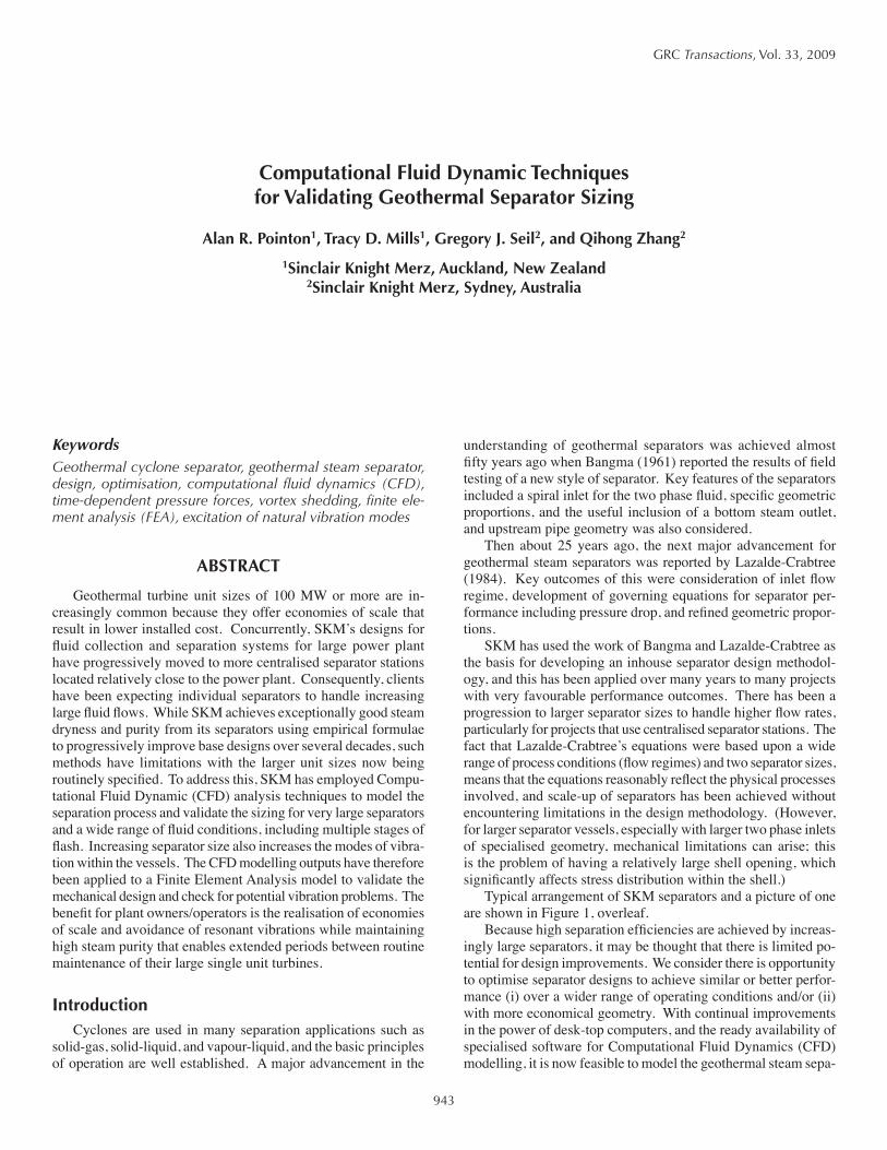
The predicted performance of the separator over its full range of flows is shown in Figure 3 (where separation performance is given in terms of outlet steam quality, i.e. dryness).
Figure 1. Typical SKM Separator Outline and Photograph.
Figure 2. Outlet Steam Quality as a function of Steam Fraction and Separator Efficiency.
945
Pointon, et al.
In addition to evaluating the effects of upstream piping and inlet flow regime (dispersed and annular flow), a key focus of the initial CFD modelling is the selection of inlet type; i.e. SKM’s standard scrolled entry versus a simple tangential entry.
Computational Fluid Dynamic Modelling MethodCFD provides a cost-effective tool for performing detailed
analysis and modelling of the flow in separation systems such as geothermal separators. There are two key areas of current interest to SKM: the first is quantification of time-varying or unsteady flow in the separation vessel and its impact on structural loading and fatigue life. The second is the impact of design changes, such as entry profiles, on separator performance. This latter area of inter-est requires an effective and computationally-efficient modelling of the basic droplet separation process.
CFD modelling to date has been based on the solving the Reynolds-averaged Navier-Stokes (RANS) equations with two-equation turbulence modelling, using the commercially-available CFD software FLUENT.
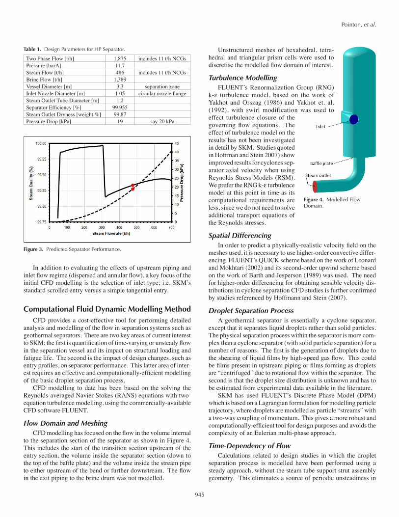
Flow Domain and MeshingCFD modelling has focused on the flow in the volume internal
to the separation section of the separator as shown in Figure 4. This includes the start of the transition section upstream of the entry section, the volume inside the separator section (down to the top of the baffle plate) and the volume inside the stream pipe to either upstream of the bend or further downstream. The flow in the exit piping to the brine drum was not modelled.
Unstructured meshes of hexahedral, tetra-hedral and triangular prism cells were used to discretise the modelled flow domain of interest.
Turbulence ModellingFLUENT’s Renormalization Group (RNG)
k-ε turbulence model, based on the work of Yakhot and Orszag (1986) and Yakhot et. al. (1992), with swirl modification was used to effect turbulence closure of the governing flow equations. The effect of turbulence model on the results has not been investigated in detail by SKM. Studies quoted in Hoffman and Stein 2007) show improved results for cyclones sep-arator axial velocity when using Reynolds Stress Models (RSM). We prefer the RNG k-ε turbulence model at this point in time as its computational requirements are less, since we do not need to solve additional transport equations of the Reynolds stresses.
Spatial DifferencingIn order to predict a physically-realistic velocity field on the
meshes used, it is necessary to use higher-order convective differ-encing. FLUENT’s QUICK scheme based on the work of Leonard and Mokhtari (2002) and its second-order upwind scheme based on the work of Barth and Jesperson (1989) was used. The need for higher-order differencing for obtaining sensible velocity dis-tributions in cyclone separation CFD studies is further confirmed by studies referenced by Hoffmann and Stein (2007).
Droplet Separation ProcessA geothermal separator is essentially a cyclone separator,
except that it separates liquid droplets rather than solid particles. The physical separation process within the separator is more com-plex than a cyclone separator (with solid particle separation) for a number of reasons. The first is the generation of droplets due to the shearing of liquid films by high-speed gas flow. This could be films present in upstream piping or films forming as droplets are “centrifuged” due to rotational flow within the separator. The second is that the droplet size distribution is unknown and has to be estimated from experimental data available in the literature.
SKM has used FLUENT’s Discrete Phase Model (DPM) which is based on a Lagrangian formulation for modelling particle trajectory, where droplets are modelled as particle “streams” with a two-way coupling of momentum. This gives a more robust and computationally-efficient tool for design purposes and avoids the complexity of an Eulerian multi-phase approach.
Time-Dependency of FlowCalculations related to design studies in which the droplet
separation process is modelled have been performed using a steady approach, without the steam tube support strut assembly geometry. This eliminates a source of periodic unsteadiness in
Table 1. Design Parameters for HP Separator.
Two Phase Flow [t/h] 1,875 includes 11 t/h NCGsPressure [barA] 11.7Steam Flow [t/h] 486 includes 11 t/h NCGsBrine Flow [t/h] 1,389Vessel Diameter [m] 3.3 separation zoneInlet Nozzle Diameter [m] 1.05 circular nozzle flangeSteam Outlet Tube Diameter [m] 1.2Separator Efficiency [%] 99.955Steam Outlet Dryness [weight %] 99.87Pressure Drop [kPa] 19 say 20 kPa
Figure 3. Predicted Separator Performance.
Figure 4. Modelled Flow Domain.
946
Pointon, et al.
the flow and significantly reduces oscillation of the flowfield with calculation iteration.
An Unsteady RANS (URANS) approach has been used to calculate unsteady flow in the separator for the purposes of estimat-ing time-dependent structural loading. In this case the steam tube support assembly is included in the calculation as it is a source of shed vorticity which propagates downstream and is ingested into the steam tube. The limitations of the URANS approach will be-come evident when there is a need to capture broadband behaviour associated with large-scale turbulent unsteady flow behaviour. In this case a Detached Eddy Simulation (DES) approach to model-ling turbulent flow is more suitable. Constantinides and Oakely (2006) show, in their study of bare and straked Vortex-Induced Vibration, that URANS leads to significant over-prediction of time-dependent lift forces on stationary cylinders due to the greater correlation of the wake flow. So in this sense a URANS approach might be more conservative.
While computationally less demanding than DES and there-fore more suitable for use as a design tool, the effectiveness of the URANS approach depends on the details of the actual flow and the extent of large-scale turbulent fluctuations. Indeed SKM is investigating the use of DES-based approaches in order to de-termine the differences between URANS results using the RNG k-ε turbulence model and DES in order to provide direction for future CFD modelling related to the determination of structural loading. A challenge will be to obtain suitable measurement data, for validation of the flow, cost-effectively.
Study of Inlet TypeSeparators generally have two types of inlet entry to the separa-
tion vessel. These are scrolled (lemniscate) and tangential entry as shown in Figure 5. SKM almost always adopts the scrolled entry, due to its superior performance.
Lemniscate entry is more like a “wrap-around” entry, whereas for tangential entry the entry section is tangential to the separation vessel. A key question is which inlet provides a higher separation efficiency and what are the physical reasons as to why a higher efficiency is achieved. This provides a good case for evaluating the usefulness of CFD as a tool for predicting the correct trend in performance.
Since fine droplets are the hardest to separate, the separa-tion efficiency ultimately depends on how well these droplets
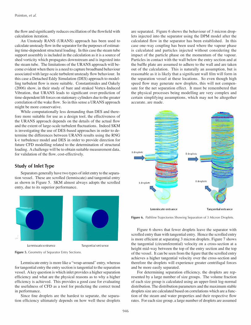
are separated. Figure 6 shows the behaviour of 3 micron drop-lets injected into the separator using the DPM model after the calculated flow in the separator has been established. In this case one-way coupling has been used where the vapour phase is calculated and particles injected without considering the impact of the particle phase on the momentum of the vapour. Particles in contact with the wall below the entry section and at the baffle plate are assumed to adhere to the wall and are taken out of the calculation. This is naturally an assumption, but is reasonable as it is likely that a significant wall film will form in the separation vessel at these locations. So even though high speed flow may generate new droplets, this will not compen-sate for the net separation effect. It must be remembered that the physical processes being modelling are very complex and certain simplifying assumptions, which may not be altogether accurate, are made.
Figure 6 shows that fewer droplets leave the separator with scrolled entry than with tangential entry. Hence the scrolled entry is more efficient at separating 3 micron droplets. Figure 7 shows the tangential (circumferential) velocity on a cross-section at a height mid-way between the top of the entry section and the top of the vessel. It can be seen from the figure that the scrolled entry achieves a higher tangential velocity over the cross-section and therefore the droplets will experience greater centrifugal forces and be more easily separated.
For determining separation efficiency, the droplets are rep-resented by a large number of size groups. The volume fraction of each size group is calculated using an upper-limit log-normal distribution. The distribution parameters and the maximum stable droplets size are calculated based on correlations which are a func-tion of the steam and water properties and their respective flow rates. For each size group, a large number of droplets are assumed
Figure 5. Geometry of Separator Entry Sections.
Figure 6. Pathline Trajectories Showing Separation of 3 Micron Droplets.

947
Pointon, et al.
to be uniformly distributed at the entrance section and are injected into the separator from their initial locations. Droplets may be absorbed by the liquid film at the vessel wall and are considered to be separated. The remaining droplets may escape with the steam flow and are therefore not separated. The total separation efficiency of the separator is then calculated as the sum total of the products of the volume fraction of the droplet size group and the fraction of the droplets being separated for that group.
The scrolled entry gave a separation efficiency of 99.96% com-pared with 99.93% for the tangential entry. Design calculations from SKM proprietary design tools based on Lazalde-Crabtree (1984) predict a separation efficiency of 99.955%. So the CFD-calculated values are in the correct range. Furthermore, in practice it has been found that the scrolled entry provides a higher separa-tion efficiency than tangential entry. Therefore CFD predicts the correct trend for entry section design.
Finite Element Analysis MethodCFD has been used to supply time-dependent structural loads
for finite element analysis (FEA) of a separator. The FEA was un-dertaken in order to determine whether the loads will excite natural frequencies in the separator structure and therefore cause fatigue of the steam tube support assembly. In this case, URANS time-
dependent calculations were used to provide the time-dependent pressure forces acting on the vessel structure, including the central steam tube. Time-dependent forces on the steam tube support assembly arising from vortex shedding behaviour (see Figure 8) were also calculated.
The finite element model of the separator, shown in Figure 9, was constructed and its mode shapes calculated. Figure 10 pro-vides an example of one such calculated mode shape.
The outer shell, collars, lemniscate and steam pipe were modelled as shell elements. The pipes were modelled as beam elements with the appropriate mass applied.
Forces were extracted on the patches shown in Figure 11, overleaf, post-processed and used as inputs to a forced response calculation.
The time-dependent stress range was examined with attention focused on the junction between the steam tube and its support assembly – see Figure 12, overleaf. A fatigue load assessment was then performed with conservative factors applied to the stress range to account for uncertainty related to both the length of the force time signal and the CFD methodology based on the URANS approach. The analysis indicated that fatigue would not be an issue and recommendations related to fabrication were made in order to further mitigate fatigue risk.
As mentioned above, SKM is investigating the use of DES-based approaches in order to determine the differences between URANS results when using the RNG k-ε turbulence model and DES in order to provide direction for future CFD modelling related to the calculation of structural loading. This should provide either
Figure 7. Cross-sectional Tangential Velocity Distribution.
Figure 8. Vortex Shedding From Steam Tube Support Strut (red contours indicate high velocity; blue contours, low velocity).
Figure 9. Finite Element Model of HP Separator.
Figure 10. Example of Steam Tube Bending and Breathing Mode.

948
Pointon, et al.
greater confidence in the RNG k-ε URANS calculations as an ac-ceptable approach to unsteady load calculation or an alternative way forward for future work.
ConclusionsA purpose of SKM’s R&D project was to determine whether
CFD analysis provides an improved means of predicting geother-mal separator performance. While initial results are promising, further CFD analysis is required, with results being compared to actual operation (notably for off-design flow rates). CFD can be used to examine particular aspects of separator design, including upstream piping arrangements, separator geometric proportions (especially shell diameter and heights relative to the inlet), per-formance of large separators, and enhancements to the entry to the steam outlet tube (which is normally sharp-edged).
The ability to easily visualise features of fluid flow within the separator is also helpful. We expect CFD analysis to provide useful insights into subtle aspects of separator design and perfor-mance, thereby improving performance, or achieving contracted performance with more economical designs. As time and work priorities permit, CFD analysis can be applied to other areas of geothermal steam separation systems, such as spray wash water injection, performance of condensate drain pots, and steam line scrubbing behaviour.
Beyond SKM’s R&D, for a specific project it has been pos-sible to utilise time-dependent pressure data from CFD analysis as inputs to an FEA model to identify whether adverse vibration modes may arise where pressure fluctuations occur at or close to the natural frequency of (part of) the separator structure. Design measures can be taken to change the pressure fluctuations and/or to modify the structure natural frequency to decouple the structure and the flow induced pressure fluctuations. We would note that while the CFD analysis used URANS, a comparison of URANS and DES simulation schemes is being undertaken.
Acknowledgements
The authors wish to acknowledge Fuji Electric Systems, Inc. for agreeing to the publication of this paper.
References
Baker, O., 1954. “Simultaneous Flow of Oil and Gas.” Oil and Gas Journal, July 26, 1954, p. 185-195.
Bangma P., 1961. “The Development and Performance of a Steam-Water Separator for Use on Geothermal Bores.” Proc. UN Conference on New Sources of Energy, Vol. 2, Geothermal Energy.
Barth, T. J. and Jesperson, D. 1989. “The Design and Application of Upwind Schemes on Unstructured Meshes.” TR AIAA-89-0366, Proc. AIAA 27th Aerospace Sciences Meeting, Reno, Nevada, USA.
Constantinides, Y. and O. H. Oakely, 2006. “Numerical Prediction of Bare and Straked Cylinder VIV.” Proc. of OMAE2006 – 25th International Conference on Offshore Mechanics and Arctic Engineering, Hamburg, Germany.
Fluent Inc., 2006. “Fluent 6.0 User’s Guide.” Lebanon, New Hampshire, USA.
Foong, K. C., 2005. “Design Concept for a More Efficient Steam-Water Separator.” Proc. World Geothermal Congress 2005.
Hoffmann, A. C. and L. E. Stein, 2007. “Gas Cyclones and Swirl Tubes – Principles, Design and Operation”, 2nd Edition, Springer.
Kocamustafaogullari G., S. R. Smits, and J. Razi, 1994. “Maximum and Mean Droplet Sizes in Annular Two-Phase Flow.” Int. J. Heat and Mass Transfer, Vol. 37, No. 6, pp. 955-965.
Lazalde-Crabtree, H. 1984. “Design Approach of Steam-Water Separators and Steam Dryers for Geothermal Applications.” Geothermal Resources Council Bulletin, Vol. 13, No. 8, p. 11-20.
Leonard, B. P. and S. Mokhtari, 1990. “ULTRA-SHARP Nonoscillatory Convection Schemes for High-Speed Steady Multidimensional Flow,” NASA TM 1-2568. (ICOMP-90-12), NASA Lewis Research Centre.
Yakhot, V. and S. A. Orszag, 1986. “Renormalization Group Analysis of Turbulence: I Basic Theory”, Journal of Scientific Computing, Vol. 1, No. 1, p. 1-51.
Yakhot, V., S. A. Orszag, S. Thangam, T. B. Gatski and C. G. Speziale, 1992. “Development of Turbulence Models for Shear Flows by a Double Expan-sion Technique”, Physics of Fluids, Vol. 4, No. 7, p. 1,510-1,520.
Figure 12. Stress Distribution at Steam Tube Support Assembly (red contours indicate high stress; blue contours, low stress).
Figure 11. Patches on CFD Model used for extracting Pressure Loads.