Notes for course EE1.1 Circuit Analysis 2004-05 …cas.ee.ic.ac.uk/people/dhaigh/EE1.1 Files/Notes/6...
37
Notes for course EE1.1 Circuit Analysis 2004-05 TOPIC 6 – PHASOR ANALYSIS OF AC CIRCUITS Objectives Representations of sinusoidal voltages and currents using phasors Using phasors to define impedance and admittance for the inductor and capacitor AC Circuit Analysis using phasors (Ohm’s law, KCL and KVL Thevenin and Norton equivalent circuits, superposition and nodal analysis) Maximum power transfer theorem for AC circuits 1 INTRODUCTION 1.1 General In this section we consider the general idea of describing circuits in terms of how they respond to input signals which are AC sinusoids We first look at some properties of circuits driven by sinusoidal sources and then consider some advantages of an approach to circuit analysis based on sinusoidal signals 1.2 The forced response of a circuit Phasor analysis is based on use of sinusoidal functions for voltage and current sources Consider our 1 st order RC circuit and its transient response for V s = 0 and v co = –5 V: -6 -5 -4 -3 -2 -1 0 0 2 4 6 8 10 12 14 16 18 20 Time s Vin(t), Vout(t) Vin(t) Vout(t) where V in (t) = V s (t) and V out (t) = v c (t) Note that the transient response decays to zero since the circuit is stable
Transcript of Notes for course EE1.1 Circuit Analysis 2004-05 …cas.ee.ic.ac.uk/people/dhaigh/EE1.1 Files/Notes/6...

Notes for course EE1.1 Circuit Analysis 2004-05
TOPIC 6 – PHASOR ANALYSIS OF AC CIRCUITS
Objectives
Representations of sinusoidal voltages and currents using phasors
Using phasors to define impedance and admittance for the inductor and capacitor
AC Circuit Analysis using phasors (Ohm’s law, KCL and KVL Thevenin and Nortonequivalent circuits, superposition and nodal analysis)
Maximum power transfer theorem for AC circuits
1 INTRODUCTION
1.1 General
In this section we consider the general idea of describing circuits in terms of how they respond toinput signals which are AC sinusoids
We first look at some properties of circuits driven by sinusoidal sources and then consider someadvantages of an approach to circuit analysis based on sinusoidal signals
1.2 The forced response of a circuit
Phasor analysis is based on use of sinusoidal functions for voltage and current sources
Consider our 1st order RC circuit and its transient response for Vs = 0 and vco = –5 V:
-6
-5
-4
-3
-2
-1
0
0 2 4 6 8 10 12 14 16 18 20
Time s
Vin
(t),
Vo
ut(
t)
Vin(t)Vout(t)
where Vin(t) = Vs(t) and Vout(t) = vc(t)
Note that the transient response decays to zero since the circuit is stable

Topic 6 – Phasor Analysis
2
Consider now the situation when Vs = Vsinωt with V = 1 V:
-6
-5
-4
-3
-2
-1
0
1
2
0 2 4 6 8 10 12 14 16 18 20
Time s
Vin
(t),
Vo
ut(
t)
Vin(t)Vout(t)
This response consists of two parts, the transient response and the response due to the forcingfunction Vsinωt
This response is called the complete response
Once the transient response has decayed to zero, the output voltage becomes sinusoidal, with thesame frequency as the input voltage but differing amplitude and phase
This response is called the sinusoidal forced response
As t → ∞, the sinusoidal forced response converges to the response the circuit would have if theexcitation was sinusoidal over all time for –∞ < t < +∞
This response is called the AC steady-state response
In fact for any circuit excited by sinusoidal voltage and current sources all having the samefrequency ω, the AC steady-state response is that all voltages and currents are sinusoidal withfrequency ω
The AC steady-state analysis problem consists in finding all of these amplitudes and phases
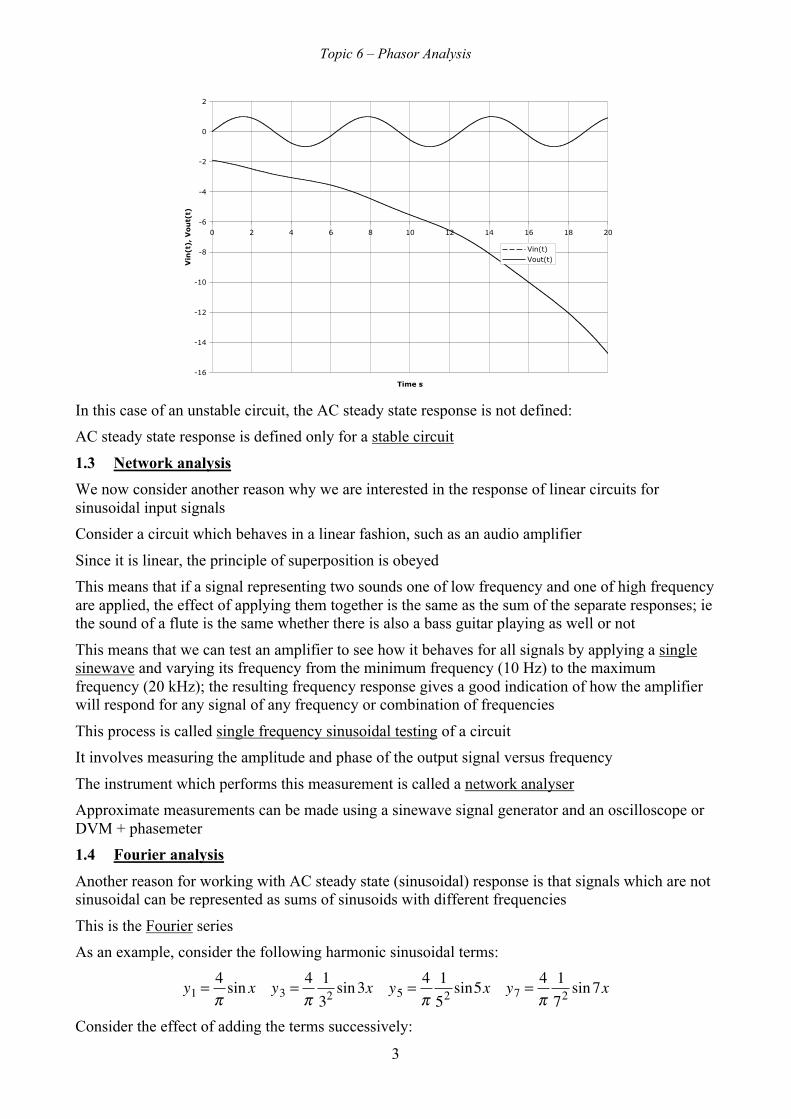
If the system is unstable, then the forced response does not converge to a sinusoidal responsebecause the transient response does not decay to zero:
Topic 6 – Phasor Analysis
3
-16
-14
-12
-10
-8
-6
-4
-2
0
2
0 2 4 6 8 10 12 14 16 18 20
Time s
Vin
(t),
Vo
ut(
t)
Vin(t)Vout(t)
In this case of an unstable circuit, the AC steady state response is not defined:
AC steady state response is defined only for a stable circuit
1.3 Network analysis
We now consider another reason why we are interested in the response of linear circuits forsinusoidal input signals
Consider a circuit which behaves in a linear fashion, such as an audio amplifier
Since it is linear, the principle of superposition is obeyed
This means that if a signal representing two sounds one of low frequency and one of high frequencyare applied, the effect of applying them together is the same as the sum of the separate responses; iethe sound of a flute is the same whether there is also a bass guitar playing as well or not
This means that we can test an amplifier to see how it behaves for all signals by applying a singlesinewave and varying its frequency from the minimum frequency (10 Hz) to the maximumfrequency (20 kHz); the resulting frequency response gives a good indication of how the amplifierwill respond for any signal of any frequency or combination of frequencies
This process is called single frequency sinusoidal testing of a circuit
It involves measuring the amplitude and phase of the output signal versus frequency
The instrument which performs this measurement is called a network analyser
Approximate measurements can be made using a sinewave signal generator and an oscilloscope orDVM + phasemeter
1.4 Fourier analysis
Another reason for working with AC steady state (sinusoidal) response is that signals which are notsinusoidal can be represented as sums of sinusoids with different frequencies
This is the Fourier series
As an example, consider the following harmonic sinusoidal terms:
�
y1 = 4π
sin x y3 = 4π
132 sin3x y5 = 4
π152 sin5x y7 = 4
π172 sin7x
Consider the effect of adding the terms successively:

Topic 6 – Phasor Analysis
4
-1.5
-1
-0.5
0
0.5
1
1.5
-4 -3 -2 -1 0 1 2 3 4
x
y
y1y3
-2
-1.5
-1
-0.5
0
0.5
1
1.5
2
-4 -3 -2 -1 0 1 2 3 4
x
y
y5y1+y3
-2
-1.5
-1
-0.5
0
0.5
1
1.5
2
-4 -3 -2 -1 0 1 2 3 4
x
y
y7y1+y3+y5
-2
-1.5
-1
-0.5
0
0.5
1
1.5
2
-4 -3 -2 -1 0 1 2 3 4
x
y
y1+y3+y5+y7
As we add successive harmonic terms, the sum approximates a triangle wave more closely
Since any periodic waveform can be represented as a sum of sinusoidal terms, we can do thefollowing:
1) Express complex waveform as a sum of sinewaves
2) Determine the response of the circuit to each sinewave
3) By superposition, the response of the circuit to the complex waveform is the sum of theresponse to the individual sinewaves
We have shown that description of circuits in terms of how they respond to sinusoidal input signalsis potentially attractive
The method of phasors allows us to simplify circuit analysis as much as possible for the sinusoidalsignal case
2 DESCRIPTION OF SINUSOIDAL VOLATGES AND CURRNTS USING PHASORS
2.1 Relationship between sine and cosine
We show the graph of two periods of x(t) = 3 cos(4πt) and two periods of y(t) = 3 sin(4πt):
Topic 6 – Phasor Analysis
5
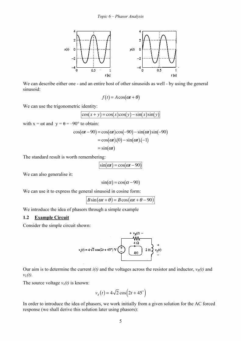
We can describe either one - and an entire host of other sinusoids as well - by using the generalsinusoid:
�
f t( ) = Acos ωt + θ( )We can use the trigonometric identity:
�
cos x + y( ) = cos x( )cos y( ) − sin x( )sin y( )with x = ωt and y = θ = –90° to obtain:
�
cos ωt − 90( ) = cos ωt( )cos −90( ) − sin ωt( )sin −90( )= cos ωt( ). 0( ) − sin ωt( ). −1( )= sin ωt( )
The standard result is worth remembering:
�
sin ωt( ) = cos ωt − 90( )We can also generalise it:
�
sin α( ) = cos α − 90( )We can use it to express the general sinusoid in cosine form:
Bsin ωt +θ( ) = Bcos ωt +θ − 90( )We introduce the idea of phasors through a simple example
1.2 Example Circuit
Consider the simple circuit shown:
Our aim is to determine the current i(t) and the voltages across the resistor and inductor, vR(t) andvL(t).
The source voltage vs(t) is known:
vs t( ) = 4 2 cos 2t + 45( )
In order to introduce the idea of phasors, we work initially from a given solution for the AC forcedresponse (we shall derive this solution later using phasors):

Topic 6 – Phasor Analysis
6
�
i t( ) = cos 2t( ) A
Let us check whether this solution is correct by checking whether Kirchhoff’s voltage law (KVL) issatisfied:
First, we find the sum of the element voltages:
�
vR t( ) + vL t( ) = Ri t( ) + Ldi t( )dt
= 4cos 2t( ) + 2 ddtcos 2t( ) = 4cos 2t( ) − 4sin 2t( )
= 4cos 2t( ) − 4cos 2t − 90( ) = 4cos 2t( ) + 4cos 2t + 90( )= 4 2 cos 2t + 45( )
Hence we have:
�
vs t( ) = vR t( ) + vL t( )KVL is satisfied, so we have confirmed that the solution we have been given is correct
We have used:
�
ddtcos at( ) = -asin at( )
The sum of a sine function and a cosine function with the same frequency is equivalent to a singlesine or cosine function with specified phase angle:
The initial form can be expressed as:
�
f = Acos x − Bsin x
We first scale numerator and denominator by a common factor:
�
f = A2 + B2 cos x AA2 + B2
− sin x BA2 + B2
⎡
⎣ ⎢
⎤
⎦ ⎥
We can now equate the factors of cos x and sin x to cos y and sin y:
�
cos x + y( ) = cos x( )cos y( ) − sin x( )sin y( )Hence
�
f = A2 + B2 cos x cos y − sin x sin y[ ]= A2 + B2 cos x + y( )
where
�
cos y = AA2 + B2
sin y = BA2 + B2
y = tan−1 BA⎡ ⎣ ⎢
⎤ ⎦ ⎥
(For the tan-1 expression, the correct quadrant must be used depending on the signs of both A andB)
�
f = Acos x − Bsin x = A2 + B2 cos x + tan−1 BA
⎛ ⎝ ⎜
⎞ ⎠ ⎟
⎛ ⎝ ⎜
⎞ ⎠ ⎟
Our task now is to generate the given solution for ourselves; in order to do this, we will firstintroduce the idea of phasors to describe voltages and currents

Topic 6 – Phasor Analysis
7
1.3 Introducing phasors
Let us write out the KVL equation for our example:
�
vs t( ) = vR t( ) + vL t( )4 2 cos 2t + 45( ) = 4cos 2t( ) + 4cos 2t + 90( )
We make use of Euler's identity:
re jθ = r cosθ + j sinθ( ) = r cosθ + jr sinθ
Using this we may state that:
r cosθ = Re re jθ⎡⎣
⎤⎦
Using this result, we can write the KVL equation as follows:
�
Re 4 2ej 2t+π
4⎛ ⎝ ⎜
⎞ ⎠ ⎟
⎡
⎣
⎢ ⎢ ⎢
⎤
⎦
⎥ ⎥ ⎥
= Re 4e j 2t( )⎡ ⎣ ⎢
⎤ ⎦ ⎥ +Re 4e
j 2t+π2
⎛ ⎝ ⎜
⎞ ⎠ ⎟
⎡
⎣
⎢ ⎢ ⎢
⎤
⎦
⎥ ⎥ ⎥
or
�
Re ˜ v s t( )[ ] = Re ˜ v R t( )[ ] +Re ˜ v L t( )[ ]where
�
˜ x denotes the vector whose real part is equal to x
This equation can be represented graphically as follows:
2t
vRvsvL
vL~
vs~
vR~
Note that all three vectors are rotating at a rate of 2 rad/sec.
Note that the vectors are complex quantities.
The procedure we have used to derive the vectors from the real parts also identifies imaginary partsaccording to Euler's identity
An equation which is true for complex quantities must be true also separately for the real parts andfor the imaginary parts of those complex quantities
It follows that our KVL equation in terms of the real parts of the vectors must be true also for thevectors themselves
Hence, we may write:

Topic 6 – Phasor Analysis
8
�
˜ v s t( ) = ˜ v R t( ) + ˜ v L t( )
4 2ej 2t+π
4⎛ ⎝ ⎜
⎞ ⎠ ⎟
= 4e j 2t( ) + 4ej 2t+π
2⎛ ⎝ ⎜
⎞ ⎠ ⎟
The final step in developing phasors is to take out from both sides of the vector equation thecommon factor ej2t; this is tantamount to removing the common rotation of all the vectors:
�
4 2e j2tej π4 = 4e j2te j0 +4e j2te
j π2
4 2ej π4 = 4e j0 +4e
j π2
Vs =VR +VLThe final quantities
�
Vs, VR and VL are referred to as phasors
The removal of ejωt is tantamount to the statement that the relationship between the vectors isindependent of their common rotation:
It is customary to indicate phasors by use of upper-case letters; in these notes, at least at thebeginning, we will use the bar as well
This emphasises the fact that phasors are transformed voltages and currents no longer directlyobservable on an oscilloscope – we need instruments such as a network analyser or gain and phasemeter.
Note that the phasors are complex numbers which may be represented in a phasor diagram
For the above example the phasor diagram is simply obtained by putting t = 0 in the vector diagram:__VL Vs
__
VR
__
Let us summarise the steps we have taken to turn a voltage or current into a phasor:
Time domain voltage or current
�
x t( ) = Xm cos ωt + θx( )
Express as real part of rotating vector
�
x t( ) = Re Xmej ωt+θ x( )⎡
⎣ ⎢ ⎤ ⎦ ⎥
Use rotating vector in place of real voltage or current
�
˜ x t( ) = Xme j ωt+θ x( )
Remove rotation of vector by setting t = 0
�
X = Xmejθ x
Once the principle of deriving phasors is accepted, the procedure may be carried out directly in asingle step:

Topic 6 – Phasor Analysis
9
�
x t( ) = Xm cos ωt + θx( ) ⇒ X = Xmejθx
Note that, in general, phasors are complex quantities and therefore may be expressed in either polaror rectangular form:
�
X = Xmejθ x = Xm∠θx = Xm cosθx + jXm sinθx
In special cases, a phasor may be wholly real or wholly imaginary
Note that the phasor does not contain the frequency of a signal and therefore the frequency (2rad/sec on our example circuit and the same for all voltages and currents) must be suppliedseparately
We have derived the phasor concept through working with cosine functions and realising that theymay be expressed as the real parts of rotating vectors
It would be equally valid to have worked with sine functions and realised that they may beexpressed as the imaginary parts of rotating vectors; in fact the vectors obtained would be the samein both cases, although the phase values in the sine function would differ from those in the cosinefunctions
In order to avoid confusion when converting between voltages as functions of time and phasors it isnecessary to be clear about whether the cosine/real part convention is being used or thesine/imaginary part one
Here, we shall always assume the cosine/real part convention
1.4 Phasor Examples1.4.1 Example 1
A voltage in a circuit has the form:
�
v t( ) = 10cos 2t − 45( ) V
Find the corresponding phasor in polar and rectangular form:
Solution:
We can immediately write the Euler form by inspection:
�
V = 10∠− 45 VNotice the standard notation: for the phasor, we use the same symbol as that for the time-varyingvoltage, only in uppercase and with an overbar
We next simply use Euler's formula to write:
V = 10cos −45( ) + j10sin −45( )= 10cos 45( ) − j10sin 45( )=
102− j 10
2= 5 2 − j5 2 V
The unit for a phasor is the same as the unit for the time quantity it represents
Topic 6 – Phasor Analysis
10
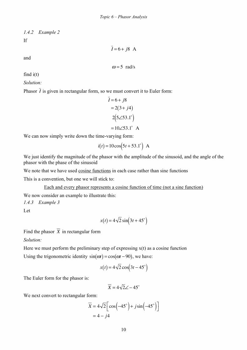
1.4.2 Example 2
If
�
I = 6 + j8 A
and
�
ω = 5 rad/sfind i(t)
Solution:
Phasor
�
I is given in rectangular form, so we must convert it to Euler form:
�
I = 6 + j8= 2 3 + j4( )2 5∠53.1( )
= 10∠53.1 AWe can now simply write down the time-varying form:
�
i t( ) = 10cos 5t + 53.1( ) A
We just identify the magnitude of the phasor with the amplitude of the sinusoid, and the angle of thephasor with the phase of the sinusoid
We note that we have used cosine functions in each case rather than sine functions
This is a convention, but one we will stick to:
Each and every phasor represents a cosine function of time (not a sine function)
We now consider an example to illustrate this:1.4.3 Example 3
Let
�
x t( ) = 4 2 sin 3t + 45( )Find the phasor
�
X in rectangular form
Solution:
Here we must perform the preliminary step of expressing x(t) as a cosine function
Using the trigonometric identity
�
sin ωt( ) = cos ωt − 90( ), we have:
�
x t( ) = 4 2 cos 3t − 45( )The Euler form for the phasor is:
�
X = 4 2∠− 45
We next convert to rectangular form:
X = 4 2 cos −45( ) + j sin −45( )⎡⎣
⎤⎦
= 4 − j4

Topic 6 – Phasor Analysis
11
Remember that the cosine is an even function and the sine is an odd one
We can now express sinusoidal voltages and currents in the form of phasors
The next step is to define the concepts of impedance and admittance which are necessary to carryout phasor analysis of a circuit
We approach the concepts of impedance and admittance through a very useful concept: the systemfunction
2 THE SYSTEM FUNCTION
We show a circuit, represented by a rectangle, having only one independent source whosewaveform x(t) is sinusoidal with amplitude Xm and phase θ:
A voltage or current variable in the circuit which is of interest, perhaps the output signal, is denotedy(t)
We know that this response will be sinusoidal, having some amplitude Ym and phase β as shown
If we can find the amplitude Ym and phase β of y(t) we will have succeeded in our analysis
The circuit with its time-varying sources is referred to as the time domain representation
To solve for the circuit response, we represent the input and response waveforms by their phasors asshown in the following figure:
Now consider the following ratio:
YX=Ym∠βXm∠θ
=YmXm
∠β −θ
where
�
φ = β −θ
We refer to
�
Y X as a system function, and write it (in polar form) as:
�
YX
= H jω( ) = H jω( )∠φ ω( )
We have:
H jω( ) = YmXm
φ ω( ) = β −θ
We express H(jω) as a function of ω in order to allow for the fact that the system function might(and generally will) change if we alter the frequency
We can rearrange the equation defining H(jω) in order to use it in an analysis procedure as follows:
�
Y = H jω( )X

Topic 6 – Phasor Analysis
12
This is equivalent to the statement that:
Y = H jω( ) X∠Y = ∠H jω( ) +∠X
We may re-write this as:
Ym = Xm H jω( )β = θ +∠H jω( )
We merely multiply the magnitudes of H(jω) and X and add their angles to find the polar form of
YNote that the system function is commonly described as the transfer function or the frequencyresponse function of a circuit
Having used phasors to define the transfer function of a system, we can now use phasors to describebasic circuit elements
3 IMPEDANCE AND ADMITTANCE
3.1 General
Consider the time-domain representation of a 2-terminal element shown with voltage v(t) andcurrent i(t):
The phasor representation is shown below:
We define the impedance of the sub-circuit to be a system function with i(t) as input and v(t) asoutput:
�
Z jω( ) = VI
= Z jω( )∠φ
Hence we have that:
�
Z jω( ) = VmIm
∠Z jω( ) = φ = ∠V −∠I = β −θ
We can reverse the situation and consider v(t) to be the input and i(t) as the output:
Topic 6 – Phasor Analysis
13
�
Y jω( ) = IV
= 1Z jω( )
= ImVm
∠−φ
In this case, the system function describing the element is called the admittance
The unit of impedance is the Ohm
The unit of admittance the Siemens
Impedance is the generalization of resistance
Admittance is the generalization of conductance.
We will now see what forms impedance and admittance have for resistors, inductors, and capacitors
3.2 The resistor
In the time-domain the resistor can be represented as follows:
In the time domain equation we use Ohm's law to write the voltage in terms of the current:
�
v t( ) = Ri t( ) = RIm cos ωt + θ( )W also have:
v t( ) = Vm cos ωt + β( )We can simply equate magnitudes and phases:
�
Vm = RImand
�
β = θ
The impedance is:
Z jω( ) = VI=Vm∠βIm∠θ
=RIm∠θIm∠θ
= R
Thus the phasor representation is as follows:
Thus, Ohm's law continues to hold for phasor description of a resistor:
�
V = RIClearly, the admittance of a resistor is easily obtained:
Y jω( ) = IV
=Im∠θVm∠β
=Im∠θRIm∠θ
=1R= G
Using conductance, Ohm's law becomes:
Topic 6 – Phasor Analysis
14
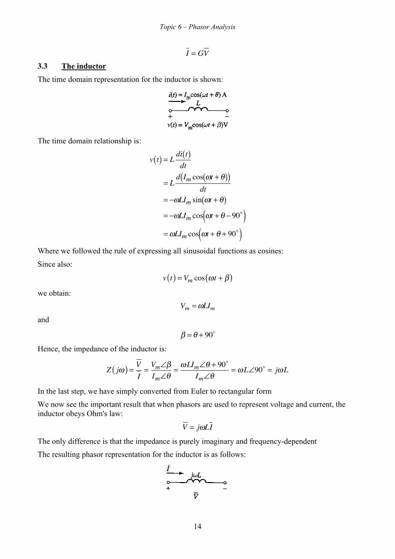
I = GV3.3 The inductor
The time domain representation for the inductor is shown:
The time domain relationship is:
�
v t( ) = Ldi t( )dt
= Ld Im cos ωt + θ( )( )
dt= −ωLIm sin ωt + θ( )= −ωLIm cos ωt + θ − 90( )
= ωLIm cos ωt + θ + 90( )Where we followed the rule of expressing all sinusoidal functions as cosines:
Since also:
v t( ) = Vm cos ωt + β( )we obtain:
�
Vm = ωLImand
�
β = θ + 90
Hence, the impedance of the inductor is:
Z jω( ) = V
I=Vm∠βIm∠θ
=ωLIm∠θ + 90
Im∠θ=ωL∠90 = jωL
In the last step, we have simply converted from Euler to rectangular form
We now see the important result that when phasors are used to represent voltage and current, theinductor obeys Ohm's law:
�
V = jωLI
The only difference is that the impedance is purely imaginary and frequency-dependent
The resulting phasor representation for the inductor is as follows:
Topic 6 – Phasor Analysis
15
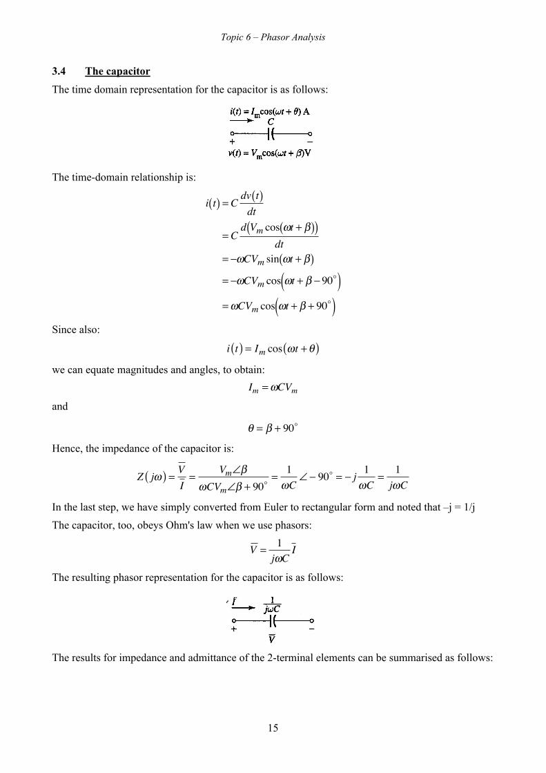
3.4 The capacitor
The time domain representation for the capacitor is as follows:
The time-domain relationship is:
�
i t( ) = Cdv t( )dt
= Cd Vm cos ωt + β( )( )
dt= −ωCVm sin ωt + β( )= −ωCVm cos ωt + β − 90( )
= ωCVm cos ωt + β + 90( )Since also:
i t( ) = Im cos ωt +θ( )we can equate magnitudes and angles, to obtain:
�
Im = ωCVmand
θ = β + 90
Hence, the impedance of the capacitor is:
Z jω( ) = V
I=
Vm∠βωCVm∠β + 90
=1
ωC∠− 90 = − j 1
ωC=
1jωC
In the last step, we have simply converted from Euler to rectangular form and noted that –j = 1/j
The capacitor, too, obeys Ohm's law when we use phasors:
�
V = 1jωC
I
The resulting phasor representation for the capacitor is as follows:
The results for impedance and admittance of the 2-terminal elements can be summarised as follows:

Topic 6 – Phasor Analysis
16
Impedance
�
Z jω( ) = VI
Admittance
�
Y jω( ) = IV
Resistor R
�
1R
= G
Inductor
�
jωL
�
1jωL
Capacitor
�
1jωC
�
jωC
Units Ohms Ω Siemens S
Here is the net result of what we have accomplished
We know that each of the elements R, L, and C obeys Ohm's law, provided we use the impedanceof the appropriate element in the place of resistance and phasors for the defining voltages andcurrents
We also know that KVL holds for phasor voltages and KCL holds for phasor currents
In fact, all of our DC analysis techniques – superposition, Thevenin and Norton equivalents, nodalanalysis, etc. – are all based upon only these facts and linearity
Thus, all of our DC analysis techniques continue to hold for AC forced response with impedancesreplacing resistances and phasors replacing time-varying voltages and currents
We are now ready to solve the problem of the simple RL circuit which we considered at the outset:
4 SOLUTION OF EXAMPLE USING PHASOR ANALYSIS
Solve for the forced response of the currents and voltages for the circuit shown using phasortechniques:
Solution
We convert all of the voltages and currents to phasors and represent the inductor and the resistor bytheir impedances:
�
Vs = 4 2∠45
Since the frequency of the signals is not contained in the phasor representations of the elements, ithas to be stated separately in the circuit diagram
The frequency is deduced as the factor of t in the argument for the cosine in the expression for thevoltage of the source; hence ω = 2 radians/second (rad/s)

Topic 6 – Phasor Analysis
17
Note that the impedance of the inductor is in general jωL
The resistor and the inductor are connected in series, so we do as we would with resistors – wesimply add their impedances:
�
Z = 4 + j4
Then we use Ohm's law with phasors to find the phasor current:
�
I = VsZ
= 4 2∠45
4 + j4= 4 2∠45
4 2∠45=1∠0
Thus:
�
i t( ) = cos 2t( ) A
We have now derived using phasors the solution for the current which we assumed earlier
We have used:
1+ j = 2∠45
The general form is of course:
a + jb = a2 + b2∠ tan−1 ba
When phase is obtained from real and imaginary parts in this way there is an ambiguity in thephase; we explore this through the following example:
Consider the problem of finding the Euler form of the phasor
�
X = – 4 – j4
We could calculate the angle as:
�
θ = tan−1 −4−4⎛ ⎝ ⎜
⎞ ⎠ ⎟ = tan−1 1( ) = 45
But this is wrong! It is the phase angle for the phasor
�
X = 4 + j4
The problem is that the tangent function has period 180° (π radians), unlike the sine and cosinewhose periods are both 360° (2 π radians)
The best way to guard against such difficulties is to retain the signs of the real and imaginary parts,and possibly make a sketch, as above
The correct angle is 180° + 45° = 225° or –180° + 45° = – 135°
In computer packages, such as Excel, this problem can be solved by use of a special functionATAN2(Ximag Xreal) which takes separate real and imaginary parts as arguments rather thanATAN(Xi/Xr) which takes the single argument Ximag/Xreal
A less serious issue that arises in working with phasors is that angles are ambiguous with respect tomultiples of 360° because of the periodic nature of the cosine function

Topic 6 – Phasor Analysis
18
This problem can be solved by restricting angles of phasors to be within the range 0 to 360° orbetween -180° and +180°
We now easily find the inductor and resistor voltages using Ohm's law for impedances
VR = IR = 4 ×1∠0 = 4∠0 = 4 V
and
VL = IZ = I jωL = j4 ×1∠0 = 4∠90 ×1∠0 = 4∠90
Therefore, we have:
�
vL t( ) = 4cos 2t + 90( ) A
and
�
vR t( ) = 4cos 2t( ) V
-6
-4
-2
0
2
4
6
0 1 2 3 4 5 6
Time (s)
Vs,
VR
an
d V
L
vsvRvL
4.1 Summary of the Phasor Method
Notes:
1) When we converted to the phasor equivalent circuit, we made a note of the frequency in asmall box
It is assumed that all voltages and currents in the circuit are cosine functions at this frequencywith amplitude and phase given by the phasors
Having the frequency clearly stated on the diagram makes it easily accessible
2) It can happen that there is confusion between impedances and phasors
Both are complex numbers, but only phasors are representative of sinusoidal time-varyingvoltages and currents

Topic 6 – Phasor Analysis
19
The impedance (or admittance) is simply a complex constant that takes the place of resistancein DC circuit analysis
The impedances (or admittances) define the relationships between the amplitudes and phasesof the phasors
Summary of phasor analysis method:
1 Convert all sine voltages and currents to cosines
2 Draw the phasor equivalent circuit, making a note of the common frequency of allindependent sources. Represent each voltage and each current by a phasor and each passiveelement by its impedance or admittance
3 Solve for the desired phasor(s)
4 Convert phasors to Euler form and write the time domain form
To illustrate the importance of the first step, we will work one more example:
Example 5
Solve for the forced response of the voltage v(t) in the circuit shown using phasor techniques:
Assume that is(t) = 10 sin(3t) A
Solution:
We first convert the current source to cosine form:
�
is t( ) = 10cos 3t − 90( ) A
Then convert voltages and currents to phasors and the passive elements to impedances, resulting inthe phasor equivalent circuit:
where
Is = 10∠− 90 = − j10 A
The two passive elements are connected in parallel, with an equivalent impedance:
Z =
3× − j4( )3− j4
=12∠− 90
5∠− 53.1=2.4∠− 36.9 Ω
Thus, the phasor voltage is given by:
V = Z I = 2.4∠− 36.9 ×10∠− 90 = 24∠−126.9 VThe corresponding time-domain sinusoidal waveform is given by:

Topic 6 – Phasor Analysis
20
�
v t( ) = 24cos 3t −126.9( ) V
5 METHODS OF AC CIRCUIT ANALYSIS
The circuit analysis methods which we have used already – Ohm's law, KCL and KVL, Theveninand Norton equivalents, superposition and nodal analysis – apply for AC analysis using phasors
We illustrate these methods in circuit analysis using phasors by means of some examples
5.1 Example 6
Find the forced response for the circuit shown using equivalent impedance and voltage division:
Solution:
We first show the circuit in phasor form:
The first step is to convert the sine function to a cosine; only then do we convert the voltage sourceto phasor form
Note that the frequency is 2 rad/s
There are many ways to solve this circuit, but we choose to find the equivalent impedance of thecapacitor and its parallel resistor:
�
Z =1× − j2( )1+ − j2( )
= − j21− j2
× 1+ j21+ j2
= 4 − j25
= 0.8 − j0.4 Ω
Note the method for rationalising a rational function:
�
z = a + jbc + jd
= a + jbc + jd
× c − jdc − jd
= ac + bdc2 + d2
+ j bc − adc2 + d2
Using this equivalent impedance, we can redraw the circuit in the equivalent form shown:
Next, we simply use the voltage divider rule (in phasor form) to compute the phasor
�
V associatedwith the voltage v(t):
�
V = ZZ + j2
Vs = 0.8 − j0.40.8 − j0.4 + j2
× − j4( ) = −1.6 − j3.20.8 + j1.6
= −2 + j0 V

Topic 6 – Phasor Analysis
21
Finally, we convert to Euler form:
�
v t( ) = −2cos 2t( )= 2cos 2t −180( ) V
5.2 Example 7
Find the forced response for i(t) in the circuit shown using element combining:
Note that ω = 3 radians/s
We compute the complex impedance of each element, convert the current source to its phasor form,and draw the phasor equivalent circuit:
This equivalent, we stress, is only valid at the single frequency of 3 rad/s
As this frequency does not appear explicitly anywhere on the circuit, we have made a note of it inthe circuit diagram
The 1 Ω resistor is connected in parallel with the capacitor and the series combination of theinductor and the 3 Ω resistor, so we compute the impedance of the subcircuit made up of all thepassive elements:
�
Z j3( ) = 1
1+ 1− j3
+ 13 + j3
= 3 + 3 j3 + 3 j −1+ j + 1
= 3 + j33 + j4
Ω
The current through the 1 Ω resistor is the same, by Ohm's law, as the voltage across it
Thus:
�
I = V1
= IsZ j3( ) = 3 + j33 + j4
× 5∠0 = 3 2∠45
5∠53.1× 5∠0 = 3 2∠− 8.1 Ω
Thus, the time-domain waveform for the forced response of the current i(t) is:
�
i t( ) = 3 2 cos 3t − 8.1( ) A
5.3 Example 8
Use KCL to determine the forced response for v(t) in the following circuit:

Topic 6 – Phasor Analysis
22
Solution
By now, the process should be familiar: we represent the sinusoidal current sources with theirphasors and convert all passive elements to impedances
This results in the circuit shown below:
We have chosen the bottom node as the reference and have labeled the other nodes with symbolsfor unknown phasor voltages
�
V and
�
VaThe KCL equation for the node labeled
�
V is:
�
V −Vaj4
+ V −Va8
+ V− j6
= 4∠− 90 = − j4
KCL for the node labeled
�
Va gives:
�
Va −Vj4
+ Va −V8
+ Va4
= 8∠0 = 8
We rationalize by multiplying the first equation by j24 and the second by j8:
�
6 V −Va( ) + j3 V −Va( ) − 4V = 96
2 Va −V( ) + j Va −V( ) + j2 Va( ) = j64
Grouping like terms:
�
2 + 3 j( )V + −6 − 3 j( )Va = 96
−2 − j( )V + 2 + 3 j( )Va = j64
We can assemble the two equations into matrix form:
�
2 + 3 j −6 − 3 j−2 − j 2 + 3 j⎡
⎣ ⎢
⎤
⎦ ⎥ ×
VVa
⎡
⎣ ⎢
⎤
⎦ ⎥ =
96j64
⎡
⎣ ⎢
⎤
⎦ ⎥
We can solve this by inverting the (2 × 2) coefficient matrix:
The general form of the matrix equation is:

Topic 6 – Phasor Analysis
23
�
a11 a12a21 a22
⎡
⎣ ⎢
⎤
⎦ ⎥ ×
x1x2
⎡
⎣ ⎢
⎤
⎦ ⎥ =
d1d2
⎡
⎣ ⎢
⎤
⎦ ⎥
which we may write:
�
A × x = dwhere
�
A =a11 a12a21 a22
⎡
⎣ ⎢
⎤
⎦ ⎥ x =
x1x2
⎡
⎣ ⎢
⎤
⎦ ⎥ d =
d1d2
⎡
⎣ ⎢
⎤
⎦ ⎥
The solution is:
�
A−1A × x =A−1dx =A−1d
where
�
A−1 = 1A
a22 −a12−a21 a11
⎡
⎣ ⎢
⎤
⎦ ⎥ =
1a11a22 − a21a12
a22 −a12−a21 a11
⎡
⎣ ⎢
⎤
⎦ ⎥
Hence
�
x1x2
⎡
⎣ ⎢
⎤
⎦ ⎥ =
1a11a22 − a21a12
a22 −a12−a21 a11
⎡
⎣ ⎢
⎤
⎦ ⎥ ×
d1d2
⎡
⎣ ⎢
⎤
⎦ ⎥
�
A = 2 + 3 j( ) 2 + 3 j( ) − −2 − j( ) −6 − 3 j( )= 4 − 9 + j6 + j6( ) − 12 − 3+ j6 + j6( )= −14
�
A−1 = 114
−2 − 3 j −6 − 3 j−2 − j −2 − 3 j
⎡
⎣ ⎢
⎤
⎦ ⎥
�
VVa
⎡
⎣ ⎢
⎤
⎦ ⎥ =
114
−2 − 3 j −6 − 3 j−2 − j −2 − 3 j
⎡
⎣ ⎢
⎤
⎦ ⎥ ×
96j64⎡
⎣ ⎢
⎤
⎦ ⎥
�
V = 114
96 −2 − 3 j( ) + j64 −6 − 3 j( )[ ] = − j67214
= − j48 = 48∠− 90
Va = 114
96 −2 − j( ) + j64 −2 − 3 j( )[ ] = − j22414
= − j16 =16∠− 90
Thus, the time-domain response we are seeking is:
�
v t( ) = 48cos 2t − 90( ) V
= 48sin 2t( ) V
MATLAB code and output for solving these equations is as follows:
A=[2+3j -6-3j;-2-j 2+3j]
b=[96 64j].'
v=A\b
mag=abs(v)
Topic 6 – Phasor Analysis
24
phase=180*atan2(imag(v),real(v))/pi
OUTPUT
A =
2.0000 + 3.0000i -6.0000 - 3.0000i
-2.0000 - 1.0000i 2.0000 + 3.0000i
b =
96.0000
0 +64.0000i
v =
0.0000 -48.0000i
-0.0000 -16.0000i
mag =
48.0000
16.0000
phase =
-90.0000
-90.0000
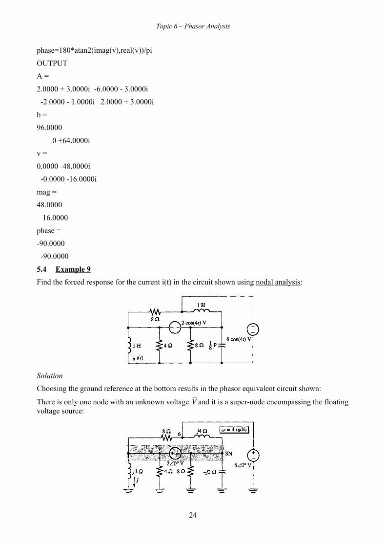
5.4 Example 9
Find the forced response for the current i(t) in the circuit shown using nodal analysis:
Solution
Choosing the ground reference at the bottom results in the phasor equivalent circuit shown:
There is only one node with an unknown voltage
�
V and it is a super-node encompassing the floatingvoltage source:

Topic 6 – Phasor Analysis
25
The voltage at node 6 is known
Thus we only need to apply KCL to the super-node:
Vj4
+V4+V − 28
+V − 2− j2
+V − 68
+V − 2 − 6
j4= 0
The solution for
�
V is:
�
V = 2 − j2
= 2 2∠− 45
Hence, we have:
�
I = Vj4
= 2 2∠− 45
4∠90= 1
2∠−135
Hence, the time-domain form for i(t) is:
�
i t( ) = 12cos 4t −135( )
6 SERIES AND PARALLEL EQUIVALENT SUB-CIRCUITS
6.1 General
Let's now investigate the idea of an equivalent sub-circuit
Consider a two-terminal passive sub-circuit in phasor form:
Let us suppose that we have computed or measured the impedance to be:
�
Z jω( ) = R ω( ) + jX ω( )where
�
R ω( ) = Re Z jω( )[ ]X ω( ) = Im Z jω( )[ ]
We call R(ω) the resistance and X(ω) the reactance of the sub-circuit
Note that the resistance of a circuit with inductors and/or capacitors can be a function of frequency
Because
�
Z jω( ) = R ω( ) + jX ω( ) , and because we know that the impedances of elements connectedin series add, we have the series equivalent sub-circuit:

Topic 6 – Phasor Analysis
26
Now let's compute the admittance:
Y jω( ) = 1Z ω( ) =
1R ω( ) + jX ω( ) =
1R ω( ) + jX ω( )
R ω( ) − jX ω( )R ω( ) − jX ω( )
=R ω( )
R2 ω( ) + X2 ω( )− j X ω( )
R2 ω( ) + X2 ω( )We refer to the real and imaginary parts of Y(jω) as the conductance G(ω) and susceptance B(ω):
�
Y jω( ) = G ω( ) + jB ω( )where
G ω( ) = Re Y jω( )⎡⎣ ⎤⎦ B ω( ) = Im Y jω( )⎡⎣ ⎤⎦
Thus we have:
G ω( ) = R ω( )R2 ω( ) + X2 ω( )
B ω( ) = −X ω( )
R2 ω( ) + X2 ω( )Thus we see that the parallel sub-circuit is also a valid equivalent for our two-terminal sub-circuit:
Note that G(ω) and B(ω) have the unit S (Siemens)
Alternatively, we can start with an admittance model of the circuit given by:
�
Y jω( ) = G ω( ) + jB ω( )Then the impedance of the parallel sub-circuit can be determined as follows:
Z jω( ) = 1Y ω( )
=1
G ω( ) + jB ω( )
=1
G ω( ) + jB ω( )G ω( ) − jB ω( )G ω( ) − jB ω( )
=G ω( )
G2 ω( ) + B2 ω( )− j B ω( )
G2 ω( ) + B2 ω( )Since:
�
Z jω( ) = R ω( ) + jX ω( )We have:
R ω( ) = G ω( )G2 ω( ) + B2 ω( )
X ω( ) = −B ω( )
G2 ω( ) + B2 ω( )
Topic 6 – Phasor Analysis
27
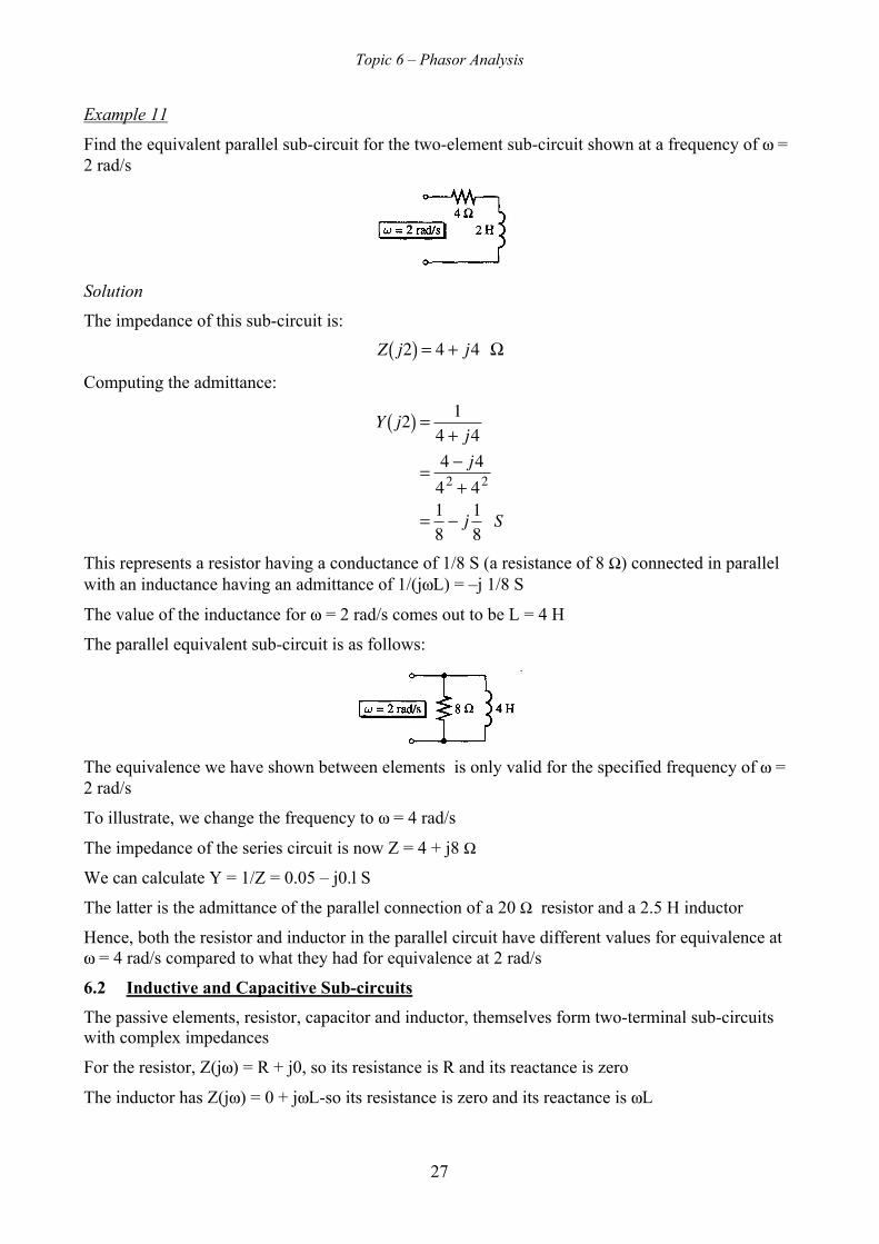
Example 11
Find the equivalent parallel sub-circuit for the two-element sub-circuit shown at a frequency of ω =2 rad/s
Solution
The impedance of this sub-circuit is:
�
Z j2( ) = 4 + j4 Ω
Computing the admittance:
�
Y j2( ) = 14 + j4
= 4 − j442 + 42
= 18− j 1
8 S
This represents a resistor having a conductance of 1/8 S (a resistance of 8 Ω) connected in parallelwith an inductance having an admittance of 1/(jωL) = –j 1/8 S
The value of the inductance for ω = 2 rad/s comes out to be L = 4 H
The parallel equivalent sub-circuit is as follows:
The equivalence we have shown between elements is only valid for the specified frequency of ω =2 rad/s
To illustrate, we change the frequency to ω = 4 rad/s
The impedance of the series circuit is now Z = 4 + j8 Ω
We can calculate Y = 1/Z = 0.05 – j0.l S
The latter is the admittance of the parallel connection of a 20 Ω resistor and a 2.5 H inductor
Hence, both the resistor and inductor in the parallel circuit have different values for equivalence atω = 4 rad/s compared to what they had for equivalence at 2 rad/s
6.2 Inductive and Capacitive Sub-circuits
The passive elements, resistor, capacitor and inductor, themselves form two-terminal sub-circuitswith complex impedances
For the resistor, Z(jω) = R + j0, so its resistance is R and its reactance is zero
The inductor has Z(jω) = 0 + jωL-so its resistance is zero and its reactance is ωL
Topic 6 – Phasor Analysis
28
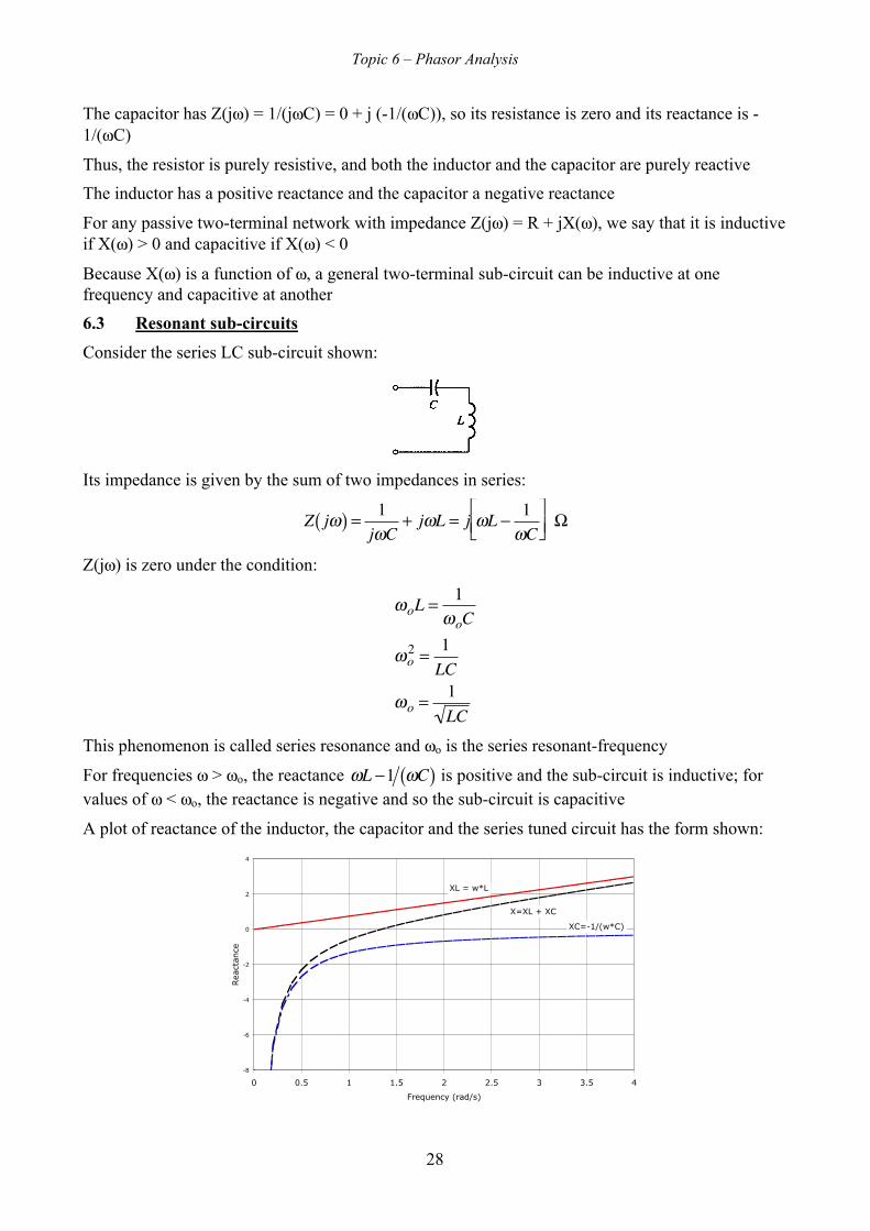
The capacitor has Z(jω) = 1/(jωC) = 0 + j (-1/(ωC)), so its resistance is zero and its reactance is -1/(ωC)
Thus, the resistor is purely resistive, and both the inductor and the capacitor are purely reactive
The inductor has a positive reactance and the capacitor a negative reactance
For any passive two-terminal network with impedance Z(jω) = R + jX(ω), we say that it is inductiveif X(ω) > 0 and capacitive if X(ω) < 0
Because X(ω) is a function of ω, a general two-terminal sub-circuit can be inductive at onefrequency and capacitive at another
6.3 Resonant sub-circuits
Consider the series LC sub-circuit shown:
Its impedance is given by the sum of two impedances in series:
�
Z jω( ) = 1jωC
+ jωL = j ωL − 1ωC
⎡ ⎣ ⎢
⎤ ⎦ ⎥ Ω
Z(jω) is zero under the condition:
�
ωoL = 1ωoC
ωo2 = 1
LC
ωo = 1LC
This phenomenon is called series resonance and ωo is the series resonant-frequency
For frequencies ω > ωo, the reactance
�
ωL −1 ωC( ) is positive and the sub-circuit is inductive; forvalues of ω < ωo, the reactance is negative and so the sub-circuit is capacitive
A plot of reactance of the inductor, the capacitor and the series tuned circuit has the form shown:
-8
-6
-4
-2
0
2
4
0 0.5 1 1.5 2 2.5 3 3.5 4
Frequency (rad/s)
Rea
ctan
ce
XL = w*L
XC=-1/(w*C)
X=XL + XC

Topic 6 – Phasor Analysis
29
At
�
ω = ωo =1 LC , the series sub-circuit has zero impedance and therefore is equivalent to a shortcircuit at that frequency
Consider now the parallel LC sub-circuit:
The impedance of the two parallel branches is given by:
Z jω( ) =1jωC
× jωL
1jωC
+ jωL= j ωL
1−ω 2LC= j 1
1ωL
−ωC Ω
The impedance is infinite at
�
ωo =1 LC
Here ωo is the parallel resonant frequency
The phenomenon itself is called parallel resonance
The parallel LC sub-circuit is inductive for ω < ωo and capacitive for larger values of ω > ωo
A plot of reactance of the inductor, the capacitor and the parallel tuned circuit has the form shown:
-10
-8
-6
-4
-2
0
2
4
6
8
10
0 0.5 1 1.5 2 2.5 3 3.5 4
Frequency (rad/s)
Rea
ctan
ce
XL = w*L
XC = -1/(w*C)
X = 1/(1/XL + 1/XC)
The parallel LC sub-circuit, , has infinite impedance at the resonant frequency and so is equivalentto an open circuit at that frequency
7 SUPERPOSITION FOR AC FORCED RESPONSE
When a circuit has two or more independent sources, some care must be taken; it is only if all theindependent sources in a circuit are sinusoidal and have the same frequency that we can draw asingle phasor equivalent
Also, the impedances of inductors and capacitors depend on frequency and therefore there must bea single operating frequency
However, analysis by superposition allows us to analyse circuits with sources having differentfrequencies

Topic 6 – Phasor Analysis
30
Since in superposition, we carry out a separate circuit analysis each with just one source, it ispossible to handle sources with different frequencies
However, it is necessary to draw a separate phasor circuit diagram for each analysis with thefrequency of the source clearly labeled; furthermore in each analysis we must use the applicablefrequency to calculate the impedances of the inductors and capacitors
Then, we convert each solution phasor back to the time domain
Then we can add the time domain expressions using superposition to obtain the total response7.1.1 Example 12
Consider the following circuit:
The voltage sources are given by:
�
vs1 t( ) = 10cos 3t( ) Vvs2 t( ) = 10cos 4t( ) V
Find the resulting forced response for v(t)
Repeat the solution if
�
vs1 t( ) = vs2 t( ) = 10cos 3t( ) V
In the first situation the sources are at different frequencies, so we are forced to use superposition
To see why on an intuitive basis, consider this: when the two sources have different frequencies,which frequency do we use in computing the inductor's impedance?
There must be a separate circuit and a separate set of impedances for each frequency
Thus, deactivating the two sources one at a time produces the two partial response equivalentcircuits shown:
Note that the different frequencies are clearly stated and that the impedance of the inductor differsin the two cases because of the change in frequency
It can easily be shown that:
�
V1 = 5 2∠45
v1 t( ) = 5 2 cos 3t + 45( ) V
V2 = 4∠36.9
v2 t( ) = 4cos 4t + 36.9( ) V
Topic 6 – Phasor Analysis
31
Thus, the solution is:
�
v t( ) = v1 t( ) + v2 t( ) = 5 2 cos 3t + 45( ) + 4 cos 4t + 36.9( ) V
When both sources are identical vs1 = vs2 = 10 cos(3t) V, we can draw a single phasor equivalent in-corporating both sources:
Using nodal analysis, the single nodal equation is:
�
V −106
+ V −106
+ Vj3
= 0
Solving, we get:
�
V = j101+ j
= 10∠90
2∠45= 5 2∠45
so that v(t) is given by:
�
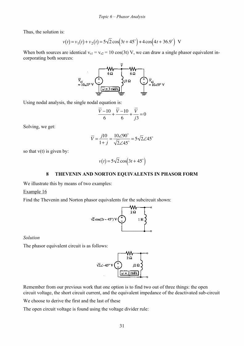
v t( ) = 5 2 cos 3t + 45( )8 THEVENIN AND NORTON EQUIVALENTS IN PHASOR FORM
We illustrate this by means of two examples:
Example 16
Find the Thevenin and Norton phasor equivalents for the subcircuit shown:
Solution
The phasor equivalent circuit is as follows:
Remember from our previous work that one option is to find two out of three things: the opencircuit voltage, the short circuit current, and the equivalent impedance of the deactivated sub-circuit
We choose to derive the first and the last of these
The open circuit voltage is found using the voltage divider rule:

Topic 6 – Phasor Analysis
32
�
Voc = j22 + j2
× 2∠− 45 = 1∠0 V
The equivalent impedance with voltage source de-activated is:
�
Z = 2 × j22 + j2
= 2∠90
2∠45= 2∠45 = 1+ j Ω
We can draw the Thevenin equivalent as shown:
We can recognize that, at the given frequency only, the j Ω impedance is equivalent to a 0.5 Hinductor:
To get the Norton equivalent, we need only find the short circuit current, which we know is theratio of open circuit voltage to equivalent impedance:
Isc =
VocZ j2( ) =
1∠0
2∠45=
12∠− 45 A
The Norton equivalent is the parallel connection of a current source having this value and theequivalent impedance:
We can interpret the equivalent impedance as a series RL circuit:
We can also use the equivalent parallel model for the equivalent impedance:
Y =1Z=
11+ j
=1− j
2=
12− j 1
2 S
This represents the parallel connection of a 2 Ω resistor and a j2 Ω inductor; this equivalence is onlyvalid at the specified frequency

Topic 6 – Phasor Analysis
33
At the stated frequency, the inductor value is 1 H
Example 17
Solve the circuit in the figure for the steady state sinusoidal response for i(t) using Theveninequivalent sub-circuits:
Solution
The phasor equivalent circuit is as follows:
We see that the two current sources have elements connected in parallel with them; hence, we canderive the Thevenin equivalent sub-circuit for each
This results in the equivalent circuit shown:
We have combined the two series Thevenin impedances (+j Ω and –j Ω) with the j4 Ω inductiveimpedance and the 4 Ω resistive impedance
This gives:
�
I =24 1− j( )4 1+ j( )
= 6∠− 90 A
Thus:
�
i t( ) = 6cos 4t − 90( ) A
Topic 6 – Phasor Analysis
34
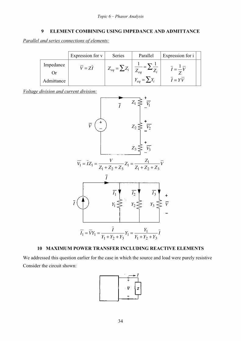
9 ELEMENT COMBINING USING IMPEDANCE AND ADMITTANCE
Parallel and series connections of elements:
Expression for v Series Parallel Expression for i
Impedance
Or
Admittance
�
V = ZI
�
Zeq = Zi∑
�
1Zeq
= 1Zi
∑
Yeq = Yi∑I = 1
ZV
I = YV
Voltage division and current division:
V
I V1
V2
V3
Z1
Z2
Z3
V1 = IZ1 =V
Z1 + Z2 + Z3Z1 =
Z1Z1 + Z2 + Z3
V
VI
I
I1 I2 I3
Y3Y2Y1
I1 = VY1 =I
Y1 +Y2 +Y3Y1 =
Y1Y1 +Y2 +Y3
I
10 MAXIMUM POWER TRANSFER INCLUDING REACTIVE ELEMENTS
We addressed this question earlier for the case in which the source and load were purely resistive
Consider the circuit shown:

Topic 6 – Phasor Analysis
35
We suppose that there is a load impedance, specified by Z, to which we are to deliver power fromthe source (represented by a ‘black box’)
We assume operation in the AC steady state
We next derive the Thevenin equivalent circuit for the source:
The load voltage (working with phasors) is given by voltage division:
�
V = ZZ + Zeq
Voc
Current
�
I is given by:
�
I = VocZ + Zeq
We now let:
�
Z = R + jXZeq = Req + jXeq
where R and X are the resistance and the reactance of the load and Req and Xeq are the resistanceand reactance of the Thevenin equivalent impedance
When working with voltage and current in phasor form, the product V × I gives what is calledcomplex power absorbed by the load (the concept of complex power will be covered later); we areinterested in real power because it is real power which produces heat in the load
Real power is given by Re V × I⎡⎣ ⎤⎦
Real power absorbed by the load is given by:
PL = Re Z
Z + Zeq( )2Voc
2⎡
⎣
⎢⎢⎢
⎤
⎦
⎥⎥⎥=
R
Z + Zeq2 Voc
2=
R
R + Req( )2 + X + Xeq( )2Voc
2
where we have written Z = R + jX and Zeq = Req + jXeq
We can now determine the conditions for maximum power transfer between the source and the load
Whether the source is given and we are to find the load or vice versa, the power in the load ismaximised if X and Xeq cancel
Hence, the condition on X and Xeq for maximum power transfer is:
X = −Xeq
Once this condition is satisfied, we have:
PL =R
R + Req( )2Voc
2

Topic 6 – Phasor Analysis
36
This is the same expression that we encountered when we found the condition for maximum powerfor resistor circuits
We showed earlier that if the source Req is given and the load R for maximum power transfer is tobe determined, the power in the load is maximised for:
R = Req
The power absorbed by the load under the maximum power condition is:
PL =1
4ReqVoc
2
Consider the following example:
Example
Consider the following load circuit:
It is to be driven from the following source circuit:
Determine the reactance Xa which maximises the poser in the load?
What is the maximum power?
Solution
We first determine the impedance of the load:
Z = R + jX = j4 +1
14− j 1
4
= j4 +4
1− j= j4 +
4 + j42
= j4 +4 + j4
2= 2 + j6 Ω
Since X = 6 Ω, the condition for maximum power transfer is Xeq = –6 Ω
The power in the load is given by:
PL =2
2 + 2( )2Voc
2=
18Voc
2 W
11 CONCLUSIONS
In this topic, we have introduced a method based on phasors for the analysis of circuits withsinusoidal voltages and currents
Using phasors we were able to define impedance and admittance for the inductor and capacitorallowing Ohm's law to be formulated for these elements

Topic 6 – Phasor Analysis
37
Previous methods for AC Circuit Analysis using phasors (Ohm’s law, KCL and KVL, Theveninand Norton equivalent circuits, superposition and nodal analysis) were shown to apply to phasors
Finally, we considered maximum a power transfer theorem for circuits containing inductors andcapacitors