Note 42 - Electrical & Computer Engineering | The University...
18
System Design and Assessment Notes Note 42 December 2014 High Power Microwave Applications Dr. Frank Peterkin Dr. Robert L Gardner, Consultant Directed Energy Warfare Office Naval Surface Warfare Center Dahlgren, VA 22222 USA ABSTRACT High power microwave weapons are complex systems consisting of many state of the art components. Some of these subsystems are prime power, pulse power, mode converter, and antenna. Each of those components must be designed to fit with the others and with the platform required for the mission. This paper describes the design process and some choices for these subsystems. Finally, some of the many efforts by international teams of scientists are described along with their capabilities.
Transcript of Note 42 - Electrical & Computer Engineering | The University...
System Design and Assessment Notes
Note 42
December 2014
High Power Microwave Applications
Dr. Frank Peterkin Dr. Robert L Gardner, Consultant
Directed Energy Warfare Office Naval Surface Warfare Center
Dahlgren, VA 22222 USA
ABSTRACT High power microwave weapons are complex systems consisting of many state of the art components. Some of these subsystems are prime power, pulse power, mode converter, and antenna. Each of those components must be designed to fit with the others and with the platform required for the mission. This paper describes the design process and some choices for these subsystems. Finally, some of the many efforts by international teams of scientists are described along with their capabilities.

HPM APPLICATIONS
1. INTRODUCTION TO DE/HPM
A high-powered microwave weapon is a device for employing radio frequency energy against a variety of targets – usually electronics. The means of generation and delivery vary with application so there are a variety of weapon design parameters. In this paper, we will consider a variety of the popular design techniques and in a subsequent paper, we will discuss a series of vignettes for fielded weapon concepts.
Figure 1: RF weapon concepts High-power microwave weapons have a number of distinct advantages over strictly kinetic energy weapons. These advantages include: 1) speed of light delivery, 2) precise engagement, 3) graduated effects – up to system kill, and 4) deep magazine. HPM weapons are typically used as counter-electronics (counter information) weapons and are a class of directed-energy weapons [1-3].
The title HPM weapon is typically used for military weapon applications of tailored radio-frequency transmissions to disrupt electronic systems with numerous other terms used to describe various applications and approaches to their use. Intentional electromagnetic interference forms a particularly interesting sub category for civilian applications. The International Electrotechnical Commission and the International Union of Radio Science have committees established to call attention to the need for hardening of civilian electronics to RF threats.
Today’s HPM weapons are large and consist of a number of components. Prime power (wall plug power) can be a limiting element of an HPM system design potentially consuming large fractions of the available volume and weight budgets. For most HPM weapons the continuous power from the prime power system must be converted to short high-power pulses. Research in pulse power has been going on in a number of countries for more than 50 years. Useful examples will be discussed later in the paper.
Target Electronics
Propagation (Range Loss)
Scattering Objects
RF Source
Antenna

HPM APPLICATIONS
PUB REF NBR (e.g. STO-MP-IST-999)
Figure 2: Narrowband HPM system with support equipment
HPM systems are usually divided into three categories, depending on the bandwidth of the transmitted waveform. Many systems, like those based on commercial radar systems are narrow band or have transmitted bandwidths of 1% or less. Narrow band systems can couple to systems very efficiently if the frequency is close to a system resonance. Extremely short pulse systems are known as ultra-wideband systems. UWB systems have instantaneous bandwidths, by some definitions, greater than 100%. Because of the large spread in bandwidth the energy in a given bandwidth (e.g., that covered by a system resonance) is small. Wideband (or mesoband) systems represent a good engineering compromise of energy in a given band exciting important resonances. Hypoband, mesoband, sub-hyperband, and hyperband systems represent another set of bandwidth categories defined on the band ratio of the systems.
Figure 3: Time and frequency domain description of three types of HPM systems
HPM APPLICATIONS
In this paper, we will outline HPM weapon system concepts using publicly available examples. We begin with a survey of uses of these systems then show how to specify an HPM system from lethality data. Each of the major components is discussed with examples and the means of developing engineering choices of component parameters. We will show the results of these choices in terms of fields at a distance and compare the results to examples of fielded systems.
2. MISSIONS AND EMPLOYMENT
2.1 HPM Mission Areas
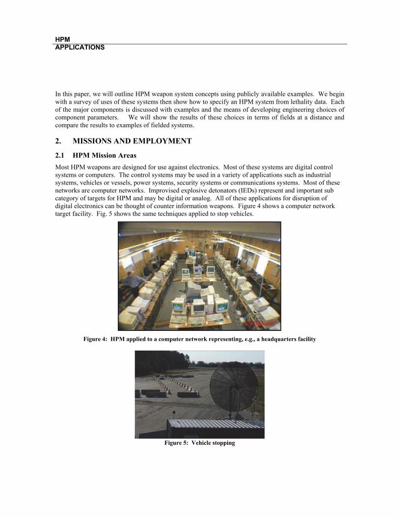
Most HPM weapons are designed for use against electronics. Most of these systems are digital control systems or computers. The control systems may be used in a variety of applications such as industrial systems, vehicles or vessels, power systems, security systems or communications systems. Most of these networks are computer networks. Improvised explosive detonators (IEDs) represent and important sub category of targets for HPM and may be digital or analog. All of these applications for disruption of digital electronics can be thought of counter information weapons. Figure 4 shows a computer network target facility. Fig. 5 shows the same techniques applied to stop vehicles.
Figure 4: HPM applied to a computer network representing, e.g., a headquarters facility
Figure 5: Vehicle stopping
HPM APPLICATIONS
PUB REF NBR (e.g. STO-MP-IST-999)
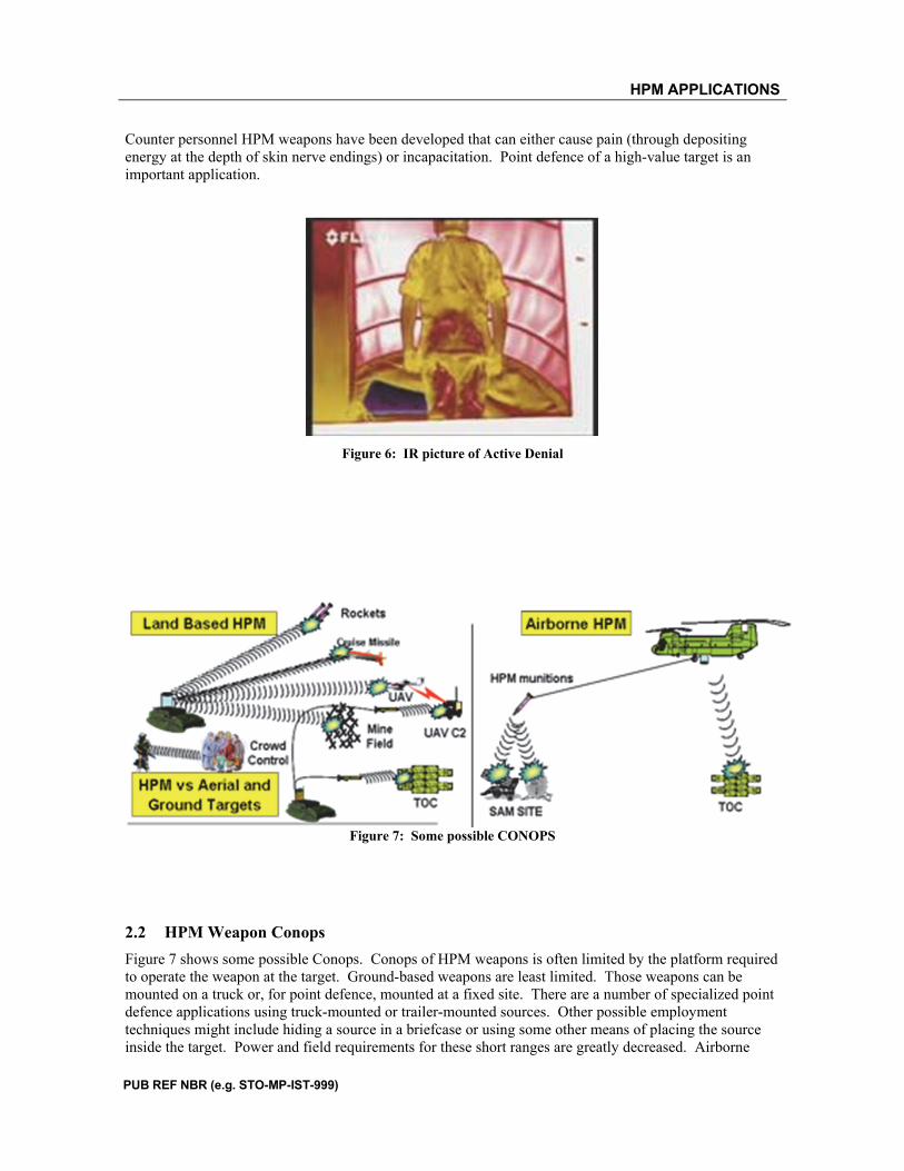
Counter personnel HPM weapons have been developed that can either cause pain (through depositing energy at the depth of skin nerve endings) or incapacitation. Point defence of a high-value target is an important application.
Figure 6: IR picture of Active Denial
Figure 7: Some possible CONOPS
2.2 HPM Weapon Conops
Figure 7 shows some possible Conops. Conops of HPM weapons is often limited by the platform required to operate the weapon at the target. Ground-based weapons are least limited. Those weapons can be mounted on a truck or, for point defence, mounted at a fixed site. There are a number of specialized point defence applications using truck-mounted or trailer-mounted sources. Other possible employment techniques might include hiding a source in a briefcase or using some other means of placing the source inside the target. Power and field requirements for these short ranges are greatly decreased. Airborne

HPM APPLICATIONS
applications are most flexible but the sources are very limited by the prime power that can be carried and the weight and volume available to the RF weapon on the platform. These ideas lead us to the concept of effects-based weapon design. In effects-based weapon design we first determine all the characteristics of the waveform required to cause the required effect on the target and then select the appropriate weapon components. We will use this concept in an example to show how this process works and, at the same time, describe the various types of components available to us for these designs.
Figure 8: MOATS HPM test facility
3. DEVELOPING A WEAPON
3.1 Lethality Data
Since HPM application designs are driven by perceived effect on the target, then we need to know how various waveforms are linked to the various effects and we have to know if those effects are tactically significant. Since there is no available analysis technique to accomplish this task, we have to gather a lot of test data. There are many facilities to develop lethality data within NATO (and without) and other talks in this lecture series on this topic, we won’t dwell on it here. For example, the US Air Force has a large
HPM APPLICATIONS
PUB REF NBR (e.g. STO-MP-IST-999)
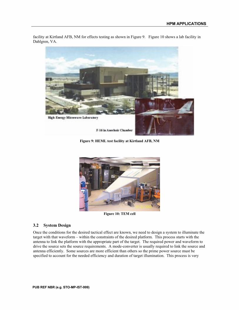
facility at Kirtland AFB, NM for effects testing as shown in Figure 9. Figure 10 shows a lab facility in Dahlgren, VA.
Figure 9: HEML test facility at Kirtland AFB, NM
Figure 10: TEM cell
3.2 System Design
Once the conditions for the desired tactical effect are known, we need to design a system to illuminate the target with that waveform – within the constraints of the desired platform. This process starts with the antenna to link the platform with the appropriate part of the target. The required power and waveform to drive the source sets the source requirements. A mode-converter is usually required to link the source and antenna efficiently. Some sources are more efficient than others so the prime power source must be specified to account for the needed efficiency and duration of target illumination. This process is very

HPM APPLICATIONS
complex and there are a number of engineering choices at each stage. Figure 11 shows an outline of the design process.
Figure 11: HPM weapon design process
4. SYSTEM COMPONENTS
Before we tackle the design process, we want to examine some of the components available to us in the design process. These examples are just some of the available tools. Research in the this area has been strong in several countries for more than 50 years.
4.1 Prime Power
Prime power is like wall-plug power. For a truck or trailer mounted system, prime power can be from a diesel generator or something like it. For mobile systems, like a UAV, weight and volume constraints are more severe. Figure 12 shows some examples of prime power that might be used.

HPM APPLICATIONS
PUB REF NBR (e.g. STO-MP-IST-999)
Figure 12: Some possible prime power sources
4.2 Pulsed Power
Pulsed power sources are used to covert the continuous power of the prime power source into a series of pulses of much higher voltage. There are a number of different designs but most are based on variations of the Marx generator. A Marx generator operates by first charging N capacitors in parallel to a voltage V. Switches are then used to discharge the capacitors in series, nominally delivering N x V to a load. Some examples are shown in Figure 13.

HPM APPLICATIONS
Figure 13: Some Marx generators and applications
4.3 RF/Microwave Generators
Voltage and current pulses must be converted into electromagnetic waves or radio-frequency transmissions. There is more design variety for the sources than the previous types of components and some of the design approaches include:
1. Vacuum or beam driven devices that include oscillators and amplifies 2. LC Oscillators (Resonant circuit elements) 3. Nonlinear transmission lines 4. High voltage/high current pulse generators for direct drive 5. Plasma switches
HPM APPLICATIONS
PUB REF NBR (e.g. STO-MP-IST-999)
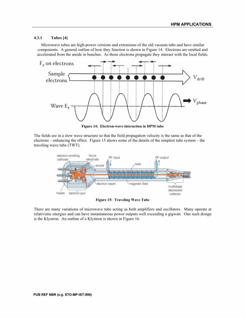
4.3.1 Tubes [4]
Microwave tubes are high-power versions and extensions of the old vacuum tube and have similar components. A general outline of how they function is shown in Figure 14. Electrons are emitted and accelerated from the anode in bunches. As those electrons propagate they interact with the local fields.
Figure 14: Electron-wave interaction in HPM tube
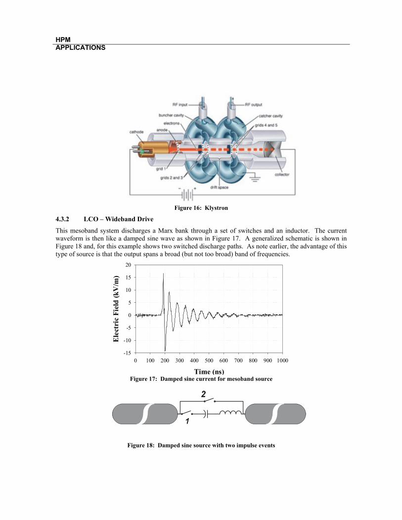
The fields are in a slow wave structure so that the field propagation velocity is the same as that of the electrons – enhancing the effect. Figure 15 shows some of the details of the simplest tube system – the traveling wave tube (TWT).
Figure 15: Traveling Wave Tube
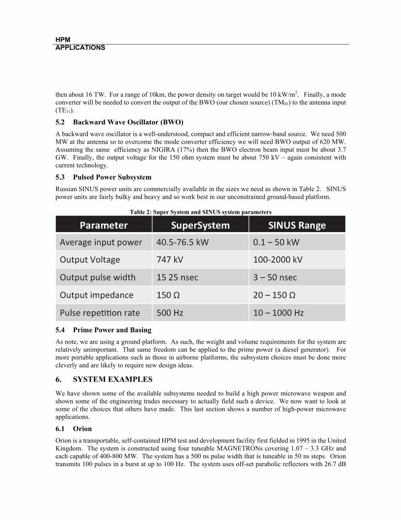
There are many variations of microwave tube acting as both amplifiers and oscillators. Many operate at relativistic energies and can have instantaneous power outputs well exceeding a gigwatt. One such design is the Klystron. An outline of a Klystron is shown in Figure 16.
HPM APPLICATIONS
Figure 16: Klystron
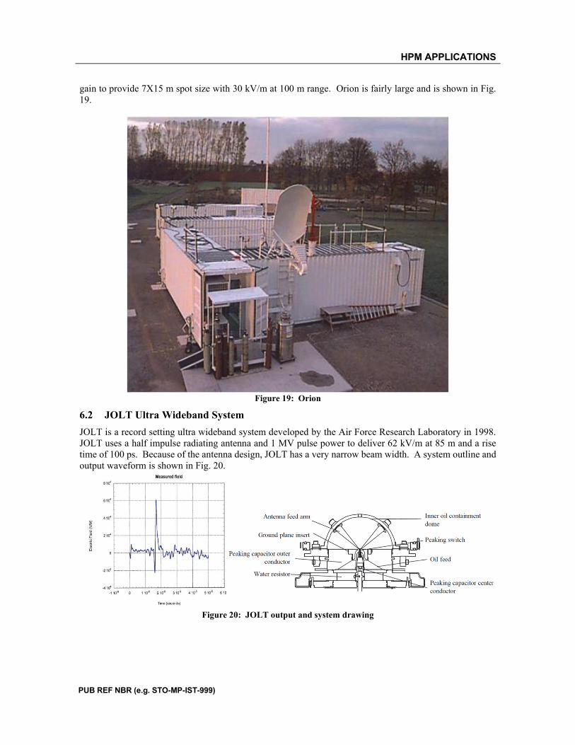
4.3.2 LCO – Wideband Drive
This mesoband system discharges a Marx bank through a set of switches and an inductor. The current waveform is then like a damped sine wave as shown in Figure 17. A generalized schematic is shown in Figure 18 and, for this example shows two switched discharge paths. As note earlier, the advantage of this type of source is that the output spans a broad (but not too broad) band of frequencies.
Figure 17: Damped sine current for mesoband source
Figure 18: Damped sine source with two impulse events
Time (ns)
0 100 200 300 400 500 600 700 800 900 1000
Ele
ctri
c F
ield
(k
V/m
)
-15
-10
-5
0
5
10
15
20

HPM APPLICATIONS
PUB REF NBR (e.g. STO-MP-IST-999)
4.4 Antennas
Antennas are used to direct the RF towards the vulnerable parts of the target. There is an important engineering trade for antennas. In general, high gain is accompanied by a narrow beam width. Narrow beam width can be desirable but we can have too narrow a beam. For a computer network target, illuminating a single computer would not cause maximum lethality to the network. For this study, we use very simple approximations for the behaviour of our antennas. Precise calculation, particularly in the presence of real ground, is more involved, but we are only looking for engineering estimates. For example, an estimate for the directivity of a circular aperture antenna is
(1)
where A is the antenna aperture area, η is the antenna efficiency, and λ represents the wavelength. We often care about the power density on target and an estimate for power density for range r is
pmax DPRAD
4 r2 (2)
where PRAD is the power density at the antenna. The 3dB beam width, θ = 2.44λ/2R.
5. DESIGN CONSIDERATIONS
Benford (Reference 1) guides us through the design of a Super System. This Super System is very much like the NIGIRA radar and we will compare the two at the end. Desired parameters for the Super System are shown in Table 1. Table 1: Super System Parameters
We now want to choose the appropriate systems and parameters for our Super System using simple formulas and efficiencies.
5.1 Antenna and Mode Converter
For the our X-band antenna we choose f = 10GHz or λ=3 cm. For 45 dB gain, the gain equation
G 5.18
2R
, tells us that we need a 2.3m diameter antenna – a manageable size. For that size antenna
the 3dB angle is 30 mrad for a spot size of about 300m at 10km. The desired effective radiated power is
D 4 2 A
4 2 R2
HPM APPLICATIONS
then about 16 TW. For a range of 10km, the power density on target would be 10 kW/m2. Finally, a mode converter will be needed to convert the output of the BWO (our chosen source) (TM01) to the antenna input (TE11).
5.2 Backward Wave Oscillator (BWO)
A backward wave oscillator is a well-understood, compact and efficient narrow-band source. We need 500 MW at the antenna so to overcome the mode converter efficiency we will need BWO output of 620 MW. Assuming the same efficiency as NIGIRA (17%) then the BWO electron beam input must be about 3.7 GW. Finally, the output voltage for the 150 ohm system must be about 750 kV – again consistent with current technology.
5.3 Pulsed Power Subsystem
Russian SINUS power units are commercially available in the sizes we need as shown in Table 2. SINUS power units are fairly bulky and heavy and so work best in our unconstrained ground-based platform.
Table 2: Super System and SINUS system parameters
5.4 Prime Power and Basing
As note, we are using a ground platform. As such, the weight and volume requirements for the system are relatively unimportant. That same freedom can be applied to the prime power (a diesel generator). For more portable applications such as those in airborne platforms, the subsystem choices must be done more cleverly and are likely to require new design ideas.
6. SYSTEM EXAMPLES
We have shown some of the available subsystems needed to build a high power microwave weapon and shown some of the engineering trades necessary to actually field such a device. We now want to look at some of the choices that others have made. This last section shows a number of high-power microwave applications.
6.1 Orion
Orion is a transportable, self-contained HPM test and development facility first fielded in 1995 in the United Kingdom. The system is constructed using four tuneable MAGNETRONs covering 1.07 – 3.3 GHz and each capable of 400-800 MW. The system has a 500 ns pulse width that is tuneable in 50 ns steps. Orion transmits 100 pulses in a burst at up to 100 Hz. The system uses off-set parabolic reflectors with 26.7 dB
HPM APPLICATIONS
PUB REF NBR (e.g. STO-MP-IST-999)
gain to provide 7X15 m spot size with 30 kV/m at 100 m range. Orion is fairly large and is shown in Fig. 19.
Figure 19: Orion
6.2 JOLT Ultra Wideband System
JOLT is a record setting ultra wideband system developed by the Air Force Research Laboratory in 1998. JOLT uses a half impulse radiating antenna and 1 MV pulse power to deliver 62 kV/m at 85 m and a rise time of 100 ps. Because of the antenna design, JOLT has a very narrow beam width. A system outline and output waveform is shown in Fig. 20.
Figure 20: JOLT output and system drawing
HPM APPLICATIONS
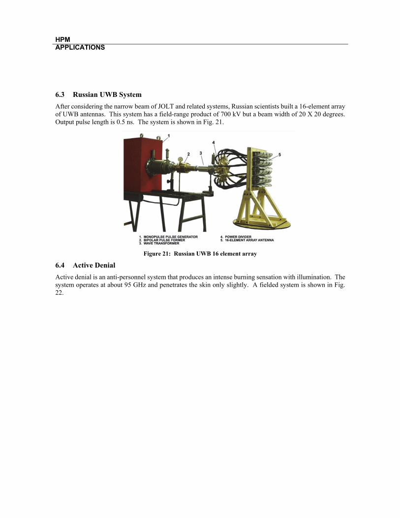
6.3 Russian UWB System
After considering the narrow beam of JOLT and related systems, Russian scientists built a 16-element array of UWB antennas. This system has a field-range product of 700 kV but a beam width of 20 X 20 degrees. Output pulse length is 0.5 ns. The system is shown in Fig. 21.
Figure 21: Russian UWB 16 element array
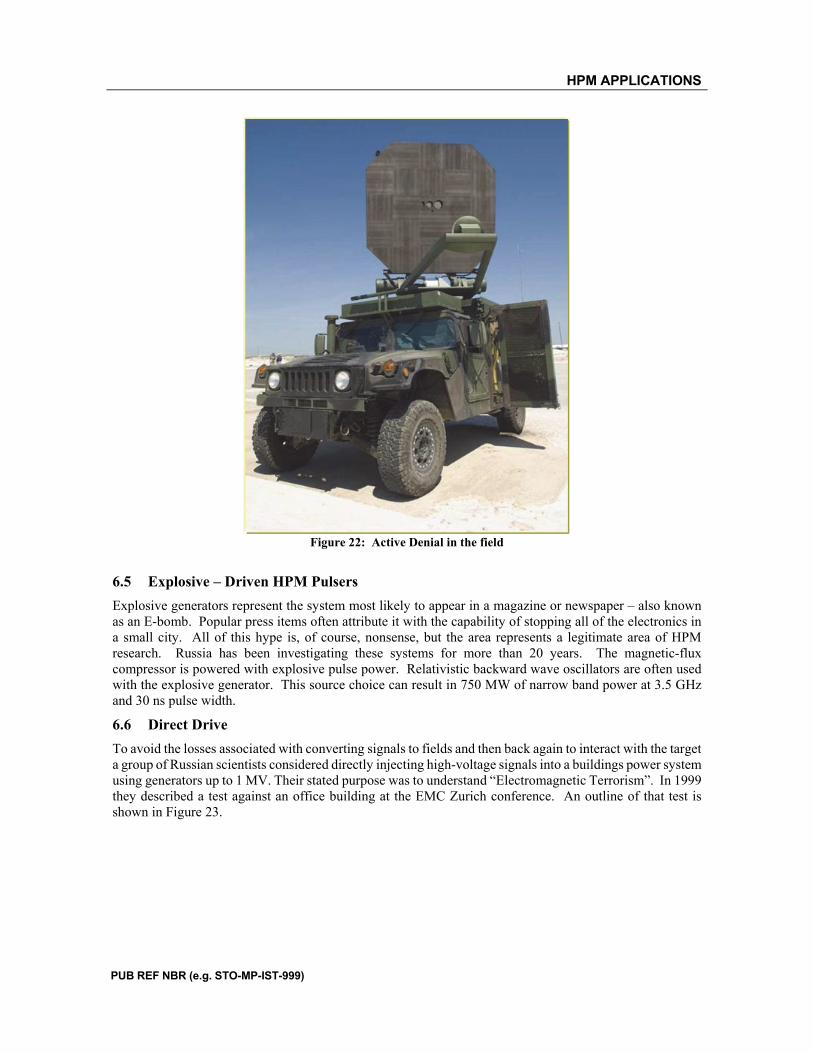
6.4 Active Denial
Active denial is an anti-personnel system that produces an intense burning sensation with illumination. The system operates at about 95 GHz and penetrates the skin only slightly. A fielded system is shown in Fig. 22.
HPM APPLICATIONS
PUB REF NBR (e.g. STO-MP-IST-999)
Figure 22: Active Denial in the field
6.5 Explosive – Driven HPM Pulsers
Explosive generators represent the system most likely to appear in a magazine or newspaper – also known as an E-bomb. Popular press items often attribute it with the capability of stopping all of the electronics in a small city. All of this hype is, of course, nonsense, but the area represents a legitimate area of HPM research. Russia has been investigating these systems for more than 20 years. The magnetic-flux compressor is powered with explosive pulse power. Relativistic backward wave oscillators are often used with the explosive generator. This source choice can result in 750 MW of narrow band power at 3.5 GHz and 30 ns pulse width.
6.6 Direct Drive
To avoid the losses associated with converting signals to fields and then back again to interact with the target a group of Russian scientists considered directly injecting high-voltage signals into a buildings power system using generators up to 1 MV. Their stated purpose was to understand “Electromagnetic Terrorism”. In 1999 they described a test against an office building at the EMC Zurich conference. An outline of that test is shown in Figure 23.

HPM APPLICATIONS
Figure 23: Direct injection test of office building from EMC Zurich 1999.
7. REFERENCES
[1] J. Benford, J. A. Swegle, and E. Schamiloglu, High Power Microwaves, 2nd ed., Taylor and Francis,2007. [2] C. D. Taylor and D. V. Giri, High-Power Microwave Systems and Effects, Taylor and Francis, New York, 1994. [3] F. M. Tesche, M Ianoz, and T. Karlsson, EMC Analysis Methods and Computational Models, IEEE Press, 1997. [4] R. J. Barker and E. Schamiloglu, High-Power Microwave Sources and Technologies, IEEE Press, 2001.