NOT MEASUREMENT MIL-STD-1518C -...
31
NOT MEASUREMENT SENSITIVE MIL-STD-1518C 1 February 2003 SUPERSEDING MIL-STD-1518B 23 May 1986 DEPARTMENT OF DEFENSE STANDARD PRACTICE STORAGE, HANDLING, AND SERVICING OF AVIATION FUELS, LUBRICATING OILS, AND HYDRAULIC FLUIDS AT CONTRACTOR FACILITIES AMSC N/A FSC 91GP Downloaded from http://www.everyspec.com
Transcript of NOT MEASUREMENT MIL-STD-1518C -...
NOT MEASUREMENT SENSITIVE
MIL-STD-1518C 1 February 2003 SUPERSEDING MIL-STD-1518B
23 May 1986
DEPARTMENT OF DEFENSE
STANDARD PRACTICE STORAGE, HANDLING, AND SERVICING OF AVIATION FUELS,
LUBRICATING OILS, AND HYDRAULIC FLUIDS AT CONTRACTOR FACILITIES
AMSC N/A FSC 91GP
Downloaded from http://www.everyspec.com
MIL-STD-1518C
ii
FOREWORD STORAGE, HANDLING, AND SERVICING OF AVIATION FUELS, LUBRICATING OILS, AND HYDRAULIC FLUIDS AT CONTRACTOR FACILITIES
1. This Military Standard is approved for use by all Departments and Agencies of the Department of Defense. 2. Beneficial comments (recommendations, additions, deletions) and any pertinent data which may be of use in improving this document should be addressed to: AF Petroleum Office, Det 3 WR-ALC/AFTH, 2430 C Street, Bldg 70, Area B, Wright-Patterson AFB OH 45433-7632., by letter or by using the self-addressed Standardization Document Improvement Proposal (DD Form 1426) appearing at the end of this document.
Downloaded from http://www.everyspec.com
MIL-STD-1518C
iii
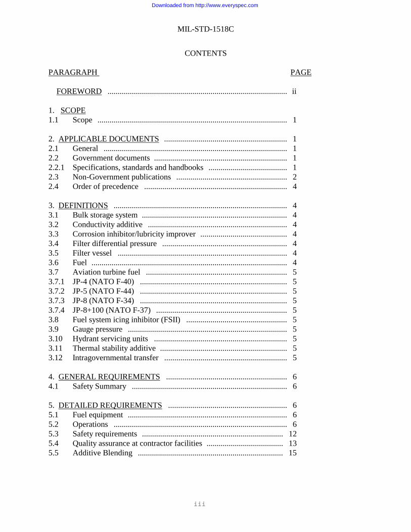
CONTENTS PARAGRAPH PAGE FOREWORD ......................................................................................... ii 1. SCOPE 1.1 Scope .............................................................................................. 1 2. APPLICABLE DOCUMENTS ............................................................. 1 2.1 General ........................................................................................... 1 2.2 Government documents .................................................................. 1 2.2.1 Specifications, standards and handbooks ....................................... 1 2.3 Non-Government publications ....................................................... 2 2.4 Order of precedence ....................................................................... 4 3. DEFINITIONS ...................................................................................... 4 3.1 Bulk storage system ........................................................................ 4 3.2 Conductivity additive ..................................................................... 4 3.3 Corrosion inhibitor/lubricity improver ........................................... 4 3.4 Filter differential pressure .............................................................. 4 3.5 Filter vessel .................................................................................... 4 3.6 Fuel ................................................................................................. 4 3.7 Aviation turbine fuel ...................................................................... 5 3.7.1 JP-4 (NATO F-40) ......................................................................... 5 3.7.2 JP-5 (NATO F-44) ......................................................................... 5 3.7.3 JP-8 (NATO F-34) ......................................................................... 5 3.7.4 JP-8+100 (NATO F-37) ................................................................. 5 3.8 Fuel system icing inhibitor (FSII) .................................................. 5 3.9 Gauge pressure ............................................................................... 5 3.10 Hydrant servicing units .................................................................. 5 3.11 Thermal stability additive ............................................................... 5 3.12 Intragovernmental transfer ............................................................. 5 4. GENERAL REQUIREMENTS ............................................................ 6 4.1 Safety Summary ............................................................................. 6 5. DETAILED REQUIREMENTS ........................................................... 6 5.1 Fuel equipment ............................................................................... 6 5.2 Operations ...................................................................................... 6 5.3 Safety requirements ...................................................................... 12 5.4 Quality assurance at contractor facilities ...................................... 13 5.5 Additive Blending ........................................................................ 15
Downloaded from http://www.everyspec.com
MIL-STD-1518C
iv
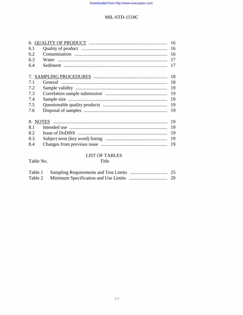
6. QUALITY OF PRODUCT .................................................................. 16 6.1 Quality of product ........................................................................ 16 6.2 Contamination .............................................................................. 16 6.3 Water ............................................................................................ 17 6.4 Sediment ....................................................................................... 17 7. SAMPLING PROCEDURES .............................................................. 18 7.1 General ......................................................................................... 18 7.2 Sample validity ............................................................................. 19 7.3 Correlation sample submission .................................................... 19 7.4 Sample size ................................................................................... 19 7.5 Questionable quality products ...................................................... 19 7.6 Disposal of samples ...................................................................... 19 8. NOTES ................................................................................................ 19 8.1 Intended use .................................................................................. 19 8.2 Issue of DoDISS ........................................................................... 19 8.3 Subject term (key word) listing .................................................... 19 8.4 Changes from previous issue ........................................................ 19
LIST OF TABLES Table No. Title Table 1 Sampling Requirements and Test Limits ............................... 25 Table 2 Minimum Specification and Use Limits ................................ 29
Downloaded from http://www.everyspec.com
MIL-STD-1518C
1
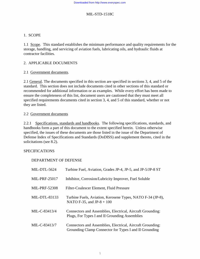
1. SCOPE 1.1 Scope. This standard establishes the minimum performance and quality requirements for the storage, handling, and servicing of aviation fuels, lubricating oils, and hydraulic fluids at contractor facilities. 2. APPLICABLE DOCUMENTS
2.1 Government documents. 2.1 General. The documents specified in this section are specified in sections 3, 4, and 5 of the standard. This section does not include documents cited in other sections of this standard or recommended for additional information or as examples. While every effort has been made to ensure the completeness of this list, document users are cautioned that they must meet all specified requirements documents cited in section 3, 4, and 5 of this standard, whether or not they are listed. 2.2 Government documents 2.2.1 Specifications, standards and handbooks. The following specifications, standards, and handbooks form a part of this document to the extent specified herein. Unless otherwise specified, the issues of these documents are those listed in the issue of the Department of Defense Index of Specifications and Standards (DoDISS) and supplement thereto, cited in the solicitations (see 8.2). SPECIFICATIONS DEPARTMENT OF DEFENSE MIL-DTL-5624 Turbine Fuel, Aviation, Grades JP-4, JP-5, and JP-5/JP-8 ST MIL-PRF-25017 Inhibitor, Corrosion/Lubricity Improver, Fuel Soluble MIL-PRF-52308 Filter-Coalescer Element, Fluid Pressure MIL-DTL-83133 Turbine Fuels, Aviation, Kerosene Types, NATO F-34 (JP-8), NATO F-35, and JP-8 + 100 MIL-C-83413/4 Connectors and Assemblies, Electrical, Aircraft Grounding: Plugs, For Types I and II Grounding Assemblies MIL-C-83413/7 Connectors and Assemblies, Electrical, Aircraft Grounding: Grounding Clamp Connector for Types I and II Grounding
Downloaded from http://www.everyspec.com
MIL-STD-1518C
2
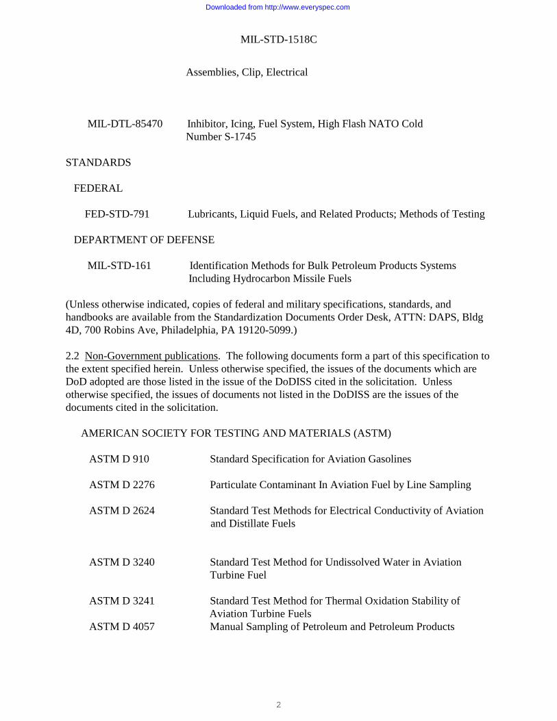
Assemblies, Clip, Electrical MIL-DTL-85470 Inhibitor, Icing, Fuel System, High Flash NATO Cold Number S-1745 STANDARDS FEDERAL FED-STD-791 Lubricants, Liquid Fuels, and Related Products; Methods of Testing DEPARTMENT OF DEFENSE MIL-STD-161 Identification Methods for Bulk Petroleum Products Systems Including Hydrocarbon Missile Fuels (Unless otherwise indicated, copies of federal and military specifications, standards, and handbooks are available from the Standardization Documents Order Desk, ATTN: DAPS, Bldg 4D, 700 Robins Ave, Philadelphia, PA 19120-5099.)
2.2 Non-Government publications. The following documents form a part of this specification to the extent specified herein. Unless otherwise specified, the issues of the documents which are DoD adopted are those listed in the issue of the DoDISS cited in the solicitation. Unless otherwise specified, the issues of documents not listed in the DoDISS are the issues of the documents cited in the solicitation.
AMERICAN SOCIETY FOR TESTING AND MATERIALS (ASTM) ASTM D 910 Standard Specification for Aviation Gasolines ASTM D 2276 Particulate Contaminant In Aviation Fuel by Line Sampling ASTM D 2624 Standard Test Methods for Electrical Conductivity of Aviation and Distillate Fuels ASTM D 3240 Standard Test Method for Undissolved Water in Aviation Turbine Fuel ASTM D 3241 Standard Test Method for Thermal Oxidation Stability of Aviation Turbine Fuels ASTM D 4057 Manual Sampling of Petroleum and Petroleum Products
Downloaded from http://www.everyspec.com
MIL-STD-1518C
3
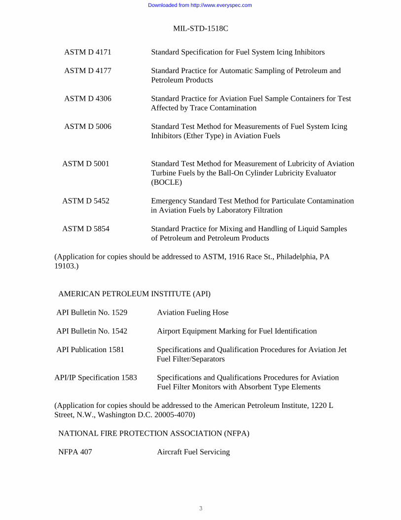
ASTM D 4171 Standard Specification for Fuel System Icing Inhibitors ASTM D 4177 Standard Practice for Automatic Sampling of Petroleum and
Petroleum Products ASTM D 4306 Standard Practice for Aviation Fuel Sample Containers for Test Affected by Trace Contamination ASTM D 5006 Standard Test Method for Measurements of Fuel System Icing
Inhibitors (Ether Type) in Aviation Fuels ASTM D 5001 Standard Test Method for Measurement of Lubricity of Aviation
Turbine Fuels by the Ball-On Cylinder Lubricity Evaluator (BOCLE)
ASTM D 5452 Emergency Standard Test Method for Particulate Contamination in Aviation Fuels by Laboratory Filtration ASTM D 5854 Standard Practice for Mixing and Handling of Liquid Samples
of Petroleum and Petroleum Products (Application for copies should be addressed to ASTM, 1916 Race St., Philadelphia, PA 19103.) AMERICAN PETROLEUM INSTITUTE (API) API Bulletin No. 1529 Aviation Fueling Hose API Bulletin No. 1542 Airport Equipment Marking for Fuel Identification API Publication 1581 Specifications and Qualification Procedures for Aviation Jet Fuel Filter/Separators API/IP Specification 1583 Specifications and Qualifications Procedures for Aviation
Fuel Filter Monitors with Absorbent Type Elements (Application for copies should be addressed to the American Petroleum Institute, 1220 L Street, N.W., Washington D.C. 20005-4070) NATIONAL FIRE PROTECTION ASSOCIATION (NFPA) NFPA 407 Aircraft Fuel Servicing
Downloaded from http://www.everyspec.com
MIL-STD-1518C
4
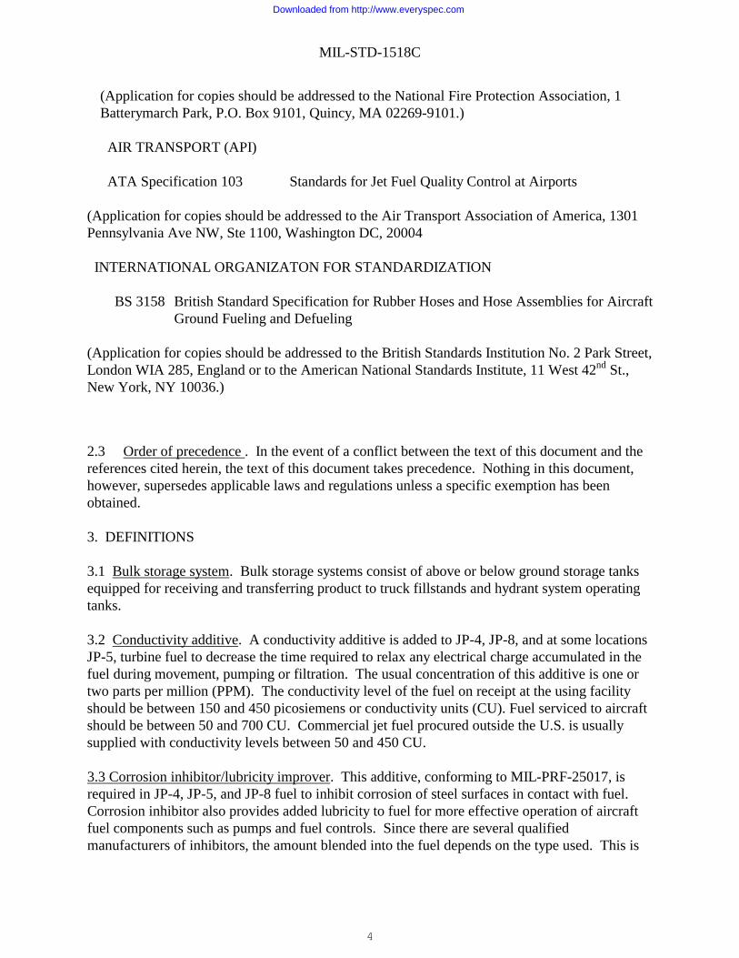
(Application for copies should be addressed to the National Fire Protection Association, 1 Batterymarch Park, P.O. Box 9101, Quincy, MA 02269-9101.) AIR TRANSPORT (API)
ATA Specification 103 Standards for Jet Fuel Quality Control at Airports
(Application for copies should be addressed to the Air Transport Association of America, 1301 Pennsylvania Ave NW, Ste 1100, Washington DC, 20004 INTERNATIONAL ORGANIZATON FOR STANDARDIZATION
BS 3158 British Standard Specification for Rubber Hoses and Hose Assemblies for Aircraft
Ground Fueling and Defueling
(Application for copies should be addressed to the British Standards Institution No. 2 Park Street, London WIA 285, England or to the American National Standards Institute, 11 West 42nd St., New York, NY 10036.)
2.3 Order of precedence . In the event of a conflict between the text of this document and the references cited herein, the text of this document takes precedence. Nothing in this document, however, supersedes applicable laws and regulations unless a specific exemption has been obtained. 3. DEFINITIONS 3.1 Bulk storage system. Bulk storage systems consist of above or below ground storage tanks equipped for receiving and transferring product to truck fillstands and hydrant system operating tanks. 3.2 Conductivity additive. A conductivity additive is added to JP-4, JP-8, and at some locations JP-5, turbine fuel to decrease the time required to relax any electrical charge accumulated in the fuel during movement, pumping or filtration. The usual concentration of this additive is one or two parts per million (PPM). The conductivity level of the fuel on receipt at the using facility should be between 150 and 450 picosiemens or conductivity units (CU). Fuel serviced to aircraft should be between 50 and 700 CU. Commercial jet fuel procured outside the U.S. is usually supplied with conductivity levels between 50 and 450 CU. 3.3 Corrosion inhibitor/lubricity improver. This additive, conforming to MIL-PRF-25017, is required in JP-4, JP-5, and JP-8 fuel to inhibit corrosion of steel surfaces in contact with fuel. Corrosion inhibitor also provides added lubricity to fuel for more effective operation of aircraft fuel components such as pumps and fuel controls. Since there are several qualified manufacturers of inhibitors, the amount blended into the fuel depends on the type used. This is
Downloaded from http://www.everyspec.com
MIL-STD-1518C
5
governed by the Qualified Products List (QPL) for MIL-PRF-25017 and ranges from a minimum of 3.15 pounds to a maximum of 11.03 pounds per 1000 barrels of jet fuel.
3.4 Filter differential pressure. The decrease in pressure as measured from the inlet to the outlet of a filter vessel. 3.5 Filter vessel. A cylindrical vessel housing filter elements (either coalescer/separator or absorption type) designed for removing solid contaminants and free water from fuel. 3.6 Fuel. Aviation gasoline or aviation turbine fuels. 3.7 Aviation turbine fuel. 3.7.1 JP-4 (NATO F-40). This grade of turbine fuel was the standard fuel for the USAF until the mid 1990’s when it was replaced with JP-8. It is produced to the requirements of MIL-DLT-5624. JP-4 contains both kerosene and gasoline fractions. It is a highly flammable material and must be handled accordingly. Commercial Jet B fuel closely conforms to JP-4 requirements in most respects. 3.7.2 JP-5 (NATO F-44). JP-5 is a high flash point (>140°F) aviation turbine fuel. It is the primary fuel for naval aircraft and is used in aircraft of all services operating off of Navy ships. It is procured to the requirements of MIL-DLT-5624. JP-5 contains both fuel system icing inhibitor and corrosion inhibitor. 3.7.3 JP-8 (NATO F-34). JP-8 is the standard fuel for US Army and USAF turbine engine powered aircraft and for some shore based Navy aircraft. This fuel is similar to commercial Jet A-1 with the addition of corrosion inhibitor, fuel system icing inhibitor and conductivity additives. It is procured to meet MIL-DLT-83133. JP-8 is the standard fuel for NATO use in Europe. 3.7.4 JP-8+100 (NATO F-37). JP-8 containing a thermal stability additive is referred to as JP-8+100 (NATO F-37). The additive improves the thermal stability of JP-8 by approximately 100°F. It reduces aircraft engine nozzle injector coking and is used primarily in fighter/trainer and selected helicopter and C-130 aircraft. Special care must be taken when handling JP-8+100. Due to its surfactant nature, it will disarm coalescer/separator elements (API 3rd edition and earlier). Replace coalescer elements in fuel servicing equipment after defueling JP-8+100. Fuel servicing equipment with absorption filter elements installed do not require element replacement. JP-8+100 that is returned to bulk storage should be diluted a minimum ratio of 1 part JP-8+100 to 100 parts of JP-8. 3.8 Fuel system icing inhibitor (FSII). FSII conforming to MIL-DTL-85470 (diethylene glycol monomethyl ether – DIEGME) is added to JP-5 and JP-8 to inhibit the formation of ice. It effectively lowers the freezing point of small quantities of free water in fuel. This precludes the formation of ice in the fuel which can clog filter elements and result in engine fuel starvation. The inhibitor also exhibits biocidal properties restricting bacterial growth in fuel systems. Water
Downloaded from http://www.everyspec.com
MIL-STD-1518C
6
removes FSII from fuel, therefore, the introduction of water into a fuel system must be avoided and free water must be removed at any point in the system where it accumulates. A drop in the FSII content of fuel is a definite indication of the presence of water in a system and requires immediate investigation and corrective action. It should be noted that FSII does not affect the freezing point of the fuel itself but only the freezing point of free water in the fuel. 3.9 Gauge pressure. Fuel pressure measured by a pressure measurement device containing a scale calibrated in pressure units, such as kilo pascals (kPa) or pounds per square inch (psi). 3.10 Hydrant servicing units. Hydrant hose trucks or hose carts, equipped with filtration, used in conjunction with hydrant systems to service aircraft. 3.11 Thermal stability additive. JP-8 containing a thermal stability additive is referred to as JP-8+100 (NATO F-37). The additive improves the thermal stability of JP-8 by approximately 100°F, from 325°F to approximately 425°F. It reduces aircraft engine nozzle injector coking and is used primarily in fighter/trainer and select helicopter and C-130 aircraft. Special care must be taken when handling JP-8+100. Due to its surfactant nature, it will disarm coalescer/separator elements (API 3rd edition and earlier, not 4th edition). Replace coalecser elements in fuel servicing equipment after defueling JP-8+100. Fuel servicing equipment with absorption cartridges installed do not require element replacement. Return to storage at a ratio of no less than 1 to 100. The JP-8+100 must be treated as a separate grade of fuel.
3.12 Intragovernmental transfer. Transfer of fuel from a government-owned location to another government-owned location. 4. GENERAL REQUIREMENTS 4.1 Safety summary. The following are general safety precautions and instructions that people must understand and apply during many phases of operations in fuel handling and laboratory operations to ensure personal safety and health and the protection of Air Force property.
WARNING AND CAUTION STATEMENTS
Practices or conditions considered essential to the protection of personnel are identified by a (WARNING). Procedures essential to the protection of equipment or property are identified by a (CAUTION). WARNING and CAUTION statements have been placed throughout this text prior to the performance of the affected step in the operation or procedure. A WARNING and CAUTION will apply each time the related step is repeated. Prior to starting any task, the WARNING or CAUTION included in the text for that task should be reviewed and understood.
SPECIAL CARE FOR CLEANERS/CHEMICALS
Keep cleaners/chemicals in approved safety containers and in minimum quantities. Some cleaners/chemicals may have an adverse effect on skin, eyes, and respiratory tracts. Observe
Downloaded from http://www.everyspec.com
MIL-STD-1518C
7
manufacturer WARNING labels and current safety directives. Use cleaners/chemicals only in authorized areas. Discard soiled cloths into safety cans.
PERSONAL PROTECTIVE EQUIPMENT The use of personal protective equipment is mandatory to ensure compliance with Occupational Safety and Health Administration, Department of Labor and standard safety practices. 5. DETAILED REQUIREMENTS 5.1 Fuel equipment. 5.1.1 Storage and handling system. 5.1.1.1 Each grade of product shall be received, stored and issued in a segregated system. 5.1.1.2 Systems and components used for receiving, storing and refueling aircraft shall be approved commercial systems designed specifically for aviation fuel use. Fuel system design guidance and restrictions on use of certain metals for components exposed to the fuel are detailed in ATA 103 and NFPA 407. Metals such as zinc and copper are limited primarily to protect the thermal stability property of fuel. 5.1.1.3 Receipt strainers. Strainers with various size openings are used as required in AFM 85-16. Clean and inspect fixed equipment strainers in accordance with AFM 85-16. (T.O 42B-1-1). 5.1.1.4 Receipt filtration. Where fuel is received directly from the supplier by pipeline, barge or tanker, fuel must pass through at least two filtrations. (T.O. 42B-1-1). 5.1.1.5 Storage tanks. Storage tanks shall be inspected and cleaned as necessary when tank samples show a continuous particle build-up or when filtration equipment elements on the downstream side of tanks show evidence of premature plugging from excessive solids. If these conditions do not occur, storage tanks shall be inspected and cleaned as necessary on the following frequencies: 5.1.1.5.1 Uncoated tanks without inlet filter separator, every 4 years. With inlet filter separator or micronic filter, every 6 years. 5.1.1.5.2 Coated tanks without inlet filter separator, every 6 years. With inlet filter separator or micronic filter, every 8 years. 5.1.2 Refueling truck product tank. The refueling truck product tank shall be constructed in accordance with SAE ARP 5818.
Downloaded from http://www.everyspec.com

MIL-STD-1518C
8
5.1.3 Filtration. Aviation fuel must pass through two separate filter separator vessels downstream of bulk storage, with at least one filtration downstream of operating tanks. (T.O. 42B-1-1). 5.1.3.1 Aviation fuel dispensed into aircraft must pass through two filtrations downstream of bulk storage. When operating tanks are installed in conjunction with bulk storage tanks, at least one of the filtration systems must be located downstream of operating tanks. The initial filter may be a filter separator, micronic filter, or full flow monitor/absorption cartridge type device. The final filtration of aviation turbine fuel must be through a filter separator or absorption monitor. One of the two filters used for aviation gasoline must be a filter separator or full flow monitor. The filters shall meet the performance requirements of API/IP 1581, API/IP 1583 or MIL-PRF-52308. Filtration equipment shall be rated equal to or greater than the pumping capacity of the system. Filtration equipment shall be designed so that bypass is not possible. 5.1.3.2 Filtration element replacement. Replacement of elements in filtration equipment is required as follows: 5.1.3.2.1. Differential pressure across the filter/separator, monitor cartridge, or micronic filter reaches the maximum recommended by the element manufacturer. 5.1.3.2.2. After 36 months in service. "Date elements are changed" should be stenciled on the filter housing or imprinted on a metal tag permanently attached to the housing. 5.1.3.2.3. When solids test on samples taken downstream of filter/separator fail. 5.1.3.2.4 When micronic filters, used downstream of bulk storage, reach 104 kPa (15 psi) differential or have been in service for two years. 5.1.4 Differential pressure. Filtration equipment shall be equipped with differential pressure gauges. The differential pressure and flow rate across each micronic filter, filter separator and absorption cartridge shall be observed daily when used and recorded weekly. 5.1.5 Pressure gauges. Pressure gauges on aircraft refueling equipment shall be calibrated within one year of the contract start date and annually thereafter. Piston type pressure differential gauges require no calibration so long as they are the type where the piston returns to zero under no flow conditions. Refer to manufacturer's maintenance manual for troubleshooting and correcting problems that occur with differential gauges. 5.1.6 Meters. Meters shall be used for quantity determination of fuel delivered to aircraft. Meters shall be calibrated to an accuracy of ±0.10% percent by volume at normal flow rates within one year of the contract start date and annually thereafter. 5.1.7 Hoses and couplings. Fuel hoses and couplings shall comply with the requirements of API 1529 or BS 3158.
Downloaded from http://www.everyspec.com
MIL-STD-1518C
9
5.1.8 Aircraft refueling nozzles. Two types of aircraft refueling nozzles are in use: gravity refueling (also known as overwing refueling nozzles) and single point refueling (also known as pressure or underwing refueling nozzles). All aircraft refueling nozzles shall be equipped with 40 mesh or finer screens that can be readily removed for inspection or cleaning. Aircraft refueling nozzle screens shall be removed, inspected and cleaned monthly. Single point nozzles shall meet the requirements of SAE AS5877 and mate to the standard aircraft fueling receptacle (MS24484). 5.1.9 Identification markings. 5.1.9.1 Fuel handling equipment. Fixed and mobile equipment shall be marked with a NATO Product Identification Code, in accordance with API Bulletin 1542 or MIL-STD-161. 5.1.9.2 Packaged products. All packaged lubricating products and hydraulic fluids are marked and identified at origin to indicate name of manufacturer, origin, nomenclature and grade, specification, batch and QPL number, lot number, date filled and NSN. Product not identified in this manner will not be serviced to government aircraft. 5.1.10 Continuity resistance. The electrical continuity of bonding reel/cable assemblies on servicing units shall be checked with a voltage/ohm meter (multi-meter) at the beginning of the contract period and every six months thereafter. Resistance, measured from the plug or clamp on the cable to the frame of the refueling equipment, shall be 10 ohms or less. 5.2 Operations. 5.2.1 The use of fuel tanks with water bottoms is prohibited. Fuel storage tanks shall have sumps for collection and draining of accumulated water. These sumps shall be checked and drained at least weekly, and more often where heavy rainfall is experienced and the storage tanks are of the open floating roof design. 5.2.2 Tank product change. 5.2.2.1 Change of product service from aviation gasoline to jet fuel, or vice versa, does not in itself require tank cleaning. The requirement for tank cleaning shall be based on the tank cleanliness and the actual need for cleaning. In most instances, if the tank has been recently cleaned, or by inspection determined to be clean, removal of all product is all that is necessary to change product in the tank. 5.2.2.2 Change of product service from black oil to clean product (aviation fuels) shall require a chemical cleaning in addition to the other cleaning operations. 5.2.3 Settling time. After each receipt or tank fill by any transportation mode, a minimum of two hours settling time is required prior to product transfer. Product received through a filter separator into a coated tank may be issued prior to two hours settling time if it is free of sediment and water.
Downloaded from http://www.everyspec.com
MIL-STD-1518C
10
5.2.4 Lock control system. Where more than one grade of fuel is stored, the issue of fuel to aircraft refuelers shall be controlled by a type of mechanical system to ensure the proper grade of fuel is serviced to aircraft. Two satisfactory methods are by the use of a lock control system or different size couplers for each grade where bottom loading is in force. An acceptable lock control system is to secure the fillstand loading arm, pump switch or any valve essential to the fillstand operation by the use of a padlock. If only one grade of product is handled, the lock control system is not necessary. 5.2.5 Servicing of drummed product. Drums containing aviation fuel should be stored on their sides to minimize the chance of drawing water into the drums from outside sources. Aviation fuel shall be passed through at least one filter separator prior to delivery into aircraft tanks. 5.2.6 Positioning equipment. 5.2.6.1 Refueling equipment shall not be moved into the servicing area if a fuel spill is within 15 meters (50 feet) of the aircraft or if fuel is leaking from the aircraft. 5.2.6.2 Fuel servicing vehicles shall not be driven closer than 8 meters (25 feet) from an aircraft unless a spotter is used to direct vehicle movement. Under no circumstances shall the vehicles be positioned closer than 3 meters (10 feet) from the aircraft. Refuelers shall be positioned so the operator's side of the equipment is adjacent to the aircraft. Always maintain a clear path from the aircraft for rapid evacuation of vehicles in an emergency situation. 5.2.7. Bonding. Prior to making any fueling connection to the aircraft, the fueling equipment shall be bonded to the aircraft by use of a metal cable, thus providing a conductive path to equalize potential between the fueling equipment and aircraft. The bond shall be maintained until fueling connections have been removed. 5.2.7.1 If ground support equipment is connected to the aircraft or if other operations are being conducted that require electrical grounding, then separate connections must be made for this purpose. Static electrical grounding points may have high resistance and therefore are unsuitable for grounding. 5.2.7.2 When the aircraft being serviced is equipped with grounding receptacles, a plug shall be used on the bonding cables of refueling equipment. The plug shall conform to MIL-C-83413/4. One source of supply for this plug is Stewart R. Browne Manufacturing Co, Inc., 1165 Hightower Trail, P.O. Box 5000008, Atlanta GA 31150, part number M83413/4-1. (www.srbrowne.com), phone (770) 993-9600 Fax (770) 594-7758). 5.2.7.3 When the aircraft being serviced is not equipped with grounding receptacles, a clamp shall be used on the bonding cables of refueling equipment. The clamp shall conform to MIL-C-83413/7. When a clamp is used, it must be connected to a bare metal surface of the aircraft. One source of supply for the clamp is Stewart R. Browne Manufacturing Co, Inc., 1156 Hightower
Downloaded from http://www.everyspec.com
MIL-STD-1518C
11
Trail, P.O. Box 5000008, Atlanta GA 31150, part number M83413/7-1. (www.srbrowne.com), phone(770) 993-9600 Fax (770) 594-7758). 5.2.7.4 In addition to the above, when overwing (gravity) refueling, the nozzle shall be bonded with a nozzle bond cable to a metallic component of the aircraft that is metallically connected to the tank filler port. The bond connection shall be made before the filler cap is removed and remain connected until the servicing is complete and the filler cap has been replaced. 5.2.8 Single point refueling. Underwing or single point refueling pressure shall not exceed 380 kPa (55 psi) nozzle pressure as indicated by the refueling equipment gauge. 5.2.9 Line displacing procedures. Displace fuel in pipeline systems if the system is inactive for over 30 days. Such action shall preclude the deterioration of fuel and protect against corrosion. Quantity to be displaced is twice the contents of the pipeline. Lines should be displaced into a refueling unit and returned to bulk storage. 5.2.10 Handling of lubricants and hydraulic fluids. 5.2.10.1 Turbine engine lubricating oil. 5.2.10.1.1 Turbine engine lubricating oils are normally furnished in 55-gallon, 1-quart, and 8- ounce containers. Aircraft engine oils will be stored inside a general-purpose warehouse. 5.2.10.1.2 Hermetically sealed 1-quart cans will be serviced directly to aircraft by using the puncture type opener with spout. Proper opening devices should be used in all cases to prevent contamination of the oil. Screwdrivers and other maintenance tools shall not be used to open hermetically sealed cans. Opening devices will be protected from airborne dirt and dust by storing in a plastic bag or similar devices when not in use. 5.2.10.1.3 Turbine engine lubrication oil furnished in 55-gallon drums may be serviced directly to engines through a 100 mesh screen. Drums of oil will be stored on their sides with bungs flooded prior to opening. After drums have been set upright and bungs have been opened, drums will be stored indoors or covered with appropriate cover to prevent water and solid debris from contaminating the oil. When not in actual use to service turbine engines, all openings to the drum will be tightly closed. Servicing nozzles will be protected from contamination by use of caps, plastic covers or other similar devices. 5.2.10.1.4 Turbine engine servicing equipment other than cans or drums. The requirements of individual aircraft technical orders will apply to specialized aircraft servicing equipment. 5.2.10.2 Reciprocating engine oil. 5.2.10.2.1 Reciprocating engine oil is furnished in 55-gallon drums and 1-quart containers.
Downloaded from http://www.everyspec.com
MIL-STD-1518C
12
5.2.10.2.2 Reciprocating engine oil furnished in 55-gallon drums will be stored on their sides with the bungs flooded prior to opening. After opening, drums will be stored inside buildings or protected from external contamination by covers. Reciprocating engine oil will be serviced to aircraft through nominal 60 mesh screens. 5.2.10.2.3 Reciprocating engine oil furnished in 1-quart containers may be serviced to aircraft without further filtration. The puncture type opener with spout will be used in all cases. Screwdrivers and other maintenance tools shall not be used for opening hermetically sealed cans. Opening devices will be protected from airborne dirt and dust by storing in a plastic bag or similar device when not in use. 5.2.10.3 Aircraft hydraulic fluid. 5.2.10.3.1 Aircraft hydraulic fluid is normally furnished in 1-quart, 1-gallon, 10-gallon, and 55- gallon drums. 5.2.10.3.2 Servicing hydraulic fluid to aircraft may be direct from the 1-quart or 1-gallon cans. In each instance, only puncture type openers with spout will be used. Maintenance tools such as screwdrivers will not be utilized for this purpose. Openers will be protected from contamination by storing in a plastic bag or other similar device when not in use. 5.2.10.3.3 Hydraulic fluid furnished in 10-or 55-gallon drums will not be serviced to aircraft except through specialized servicing equipment. Such equipment will contain a nominal 5 micron filter in the servicing system. Servicing connections will be protected from external contamination by covering hose ends with plugs or caps and placing connection in plastic bags. 5.2.10.3.4 Unused portions of 1-quart or 1-gallon containers of hydraulic fluid or engine lubricating oil will be discarded or transferred to servicing equipment. 5.3 Safety requirements. The safety requirements specified in NFPA 407 or the equivalent nationaldocument shall apply. Local fire and accident prevention regulations and requirements including the following shall be complied with: 5.3.1 Smoking and/or open flames or sources of ignition shall be prohibited within 15 meters (50 feet) of fuel operations. 5.3.2 After each receipt or tank fill by any transportation mode, a minimum of two hours settling time is required prior to product transfer. Product received through a filter separator or micronic filter into a coated tank may be issued prior to two hours settling time. 5.3.3 Areas where aircraft are serviced shall be kept free of combustible materials. Refueling equipment compartments and surfaces shall be kept free of debris, accumulated oil, grease, and fuel. These areas shall be kept clear of objects that can be ingested by engines.
Downloaded from http://www.everyspec.com
MIL-STD-1518C
13
5.3.4 Servicing personnel shall be trained how to use fire extinguishers and in the procedures to follow in the event of fire. 5.3.5 At least two serviceable, charged fire extinguishers shall be available in the immediate vicinity of each servicing operation. Access to the fire extinguisher shall be unobstructed. Minimum sizes and types shall be specified and approved by the fire department and shall be designed for extinguishing flammable liquids with a minimum discharge time of not less than 25 seconds. 5.3.6 The fuel servicing operator shall remain at the fuel servicing equipment and continuously observe the equipment and aircraft for fuel leaks. Servicing operations shall be stopped whenever a leak or deficiency of a hazardous nature is detected. 5.3.7 Aircraft with an operating radar or radio shall not be serviced. Likewise, aircraft shall not be serviced when there are electrical storms within a five-mile radius. 5.3.8 Servicing personnel shall not wear 100 percent nylon outer garments and shall not remove or put on clothing during servicing. 5.4 Quality assurance at contractor facilities. The purpose of this section is to establish minimum quality procedures required to deliver clean, dry fuel to aircraft on a continuing basis. The contractor is required to maintain written quality control procedures covering (1) source of fuel supply, (2) receiving, (3) storing, (4) servicing, (5) sampling and testing, (6) calibration of measuring and test equipment, (7) safety, (8) maintenance, (9) reports and (10) corrective actions. 5.4.1 Sample submission. 5.4.1.1 The contractor is required to obtain, package and ship samples of each grade of aviation fuel to a testing laboratory designated in the contract. The sample size shall be one gallon for each grade of fuel handled and must be accompanied by a completed DD Form 1222 or an AFTO Form 475. For turbine fuel, the frequency of sample submission shall be at the beginning of each contract period and once every three months thereafter. For aviation gasoline, the frequency of sample submission shall be at the beginning of each contract period and once every six months thereafter. Samples may be submitted to an Aerospace Fuels Laboratory any time doubt exists as to the quality or identity of petroleum products in storage or use. These samples will be authorized by the Quality Assurance Representative with fuel surveillance responsibility at that facility. 5.4.1.1.1 Samples shall be taken in an epoxy coated can suitable for thermal stability testing as defined in ASTM D 4306. One source of supply for the can is Gammon Technical Products, 2300 Highway 34, Manasquan NJ 08736, part number TL2935A-1. Approximately 24 hours prior to sampling, fill the can with filtered fuel (of the same grade to be sampled). Immediately prior to sampling, empty the can, rinse the can with the fuel to be sampled and then obtain the sample.
Downloaded from http://www.everyspec.com
MIL-STD-1518C
14
5.4.1.1.2 The sample to be submitted for testing shall be taken during flow downstream of the last filtration vessel prior to the aircraft or engine test cell. 5.4.1.2 The analysis of turbine fuel samples at testing laboratories shall consist of flash point, freeze point, thermal stability, Ball-On Cylinder Lubricity Evaluator (BOCLE) in accordance with ASTM D-5001and FSII if contract requires FSII to be in fuel. The thermal stability property shall be performed in accordance with ASTM D 3241 and have a heater tube temperature of 260°C. The analysis of aviation gasoline samples shall consist of distillation, vapor pressure, copper strip corrosion and freeze point. 5.4.2 Contractor sampling requirements. The contractor is responsible for performing all sampling and testing required in table I. The validity of test results is greatly influenced by sampling procedures. The representative character of the sample is dependent upon the type and cleanliness of the sample container, the sampling operation, and the purpose for which the sample is being taken. The basic principle of any sampling procedure is to obtain a sample or composite of several samples in such a manner that the sample to be submitted for testing will be truly representative of the product. 5.4.3 Aircraft defueling. Before starting the defuel operation, determine the type of fuel contained in the aircraft. Aircraft sumps shall then be drained to discard water and excess sediment. Defueled product should be returned to the aircraft if there is no reason to suspect contamination. If fuel cannot be returned to the aircraft, follow the defuel/servicing clause in the contract. When returned to aircraft, fuel must pass through a filter separator or fuel monitor. 5.4.4 Change of product grade. 5.4.4.1 In the event of a product change from jet fuel to aviation gasoline or vice-versa, drain the unit, including residual fuel in the filter separator assembly and hoses. Fill the unit with the new grade of fuel, circulate at least 946 l (250 gal) through each pump hose assembly. Obtain a sample from the downstream side of the filter. Sample must be visually free of sediment and water. 5.4.4.2 Change the servicing controls as necessary and the unit markings to reflect the grade of fuel. 5.4.5 Records and quality checks required. 5.4.5.1 Tank cleaning in accordance with paragraph 5.1.1.5. 5.4.5.2 Filter element replacement in accordance with paragraph 5.1.3.2. 5.4.5.3 Daily differential pressure checks across filtration equipment and weekly recording. 5.4.5.4 Yearly calibration of meters and pressure gauges.
Downloaded from http://www.everyspec.com
MIL-STD-1518C
15
5.4.5.5 Monthly cleaning of nozzle screens on servicing equipment. 5.4.5.6 Beginning of contract period and six month continuity check of bonding reel/cable assemblies on servicing units. 5.4.5.7 Weekly draining of storage tank sumps. 5.4.5.8 Maintain written quality control procedures. 5.4.5.9 Beginning of contract period and every three months for testing of turbine fuel downstream of last filtration vessel. 5.4.5.10 Beginning of contract period and every six months for testing of aviation gasoline downstream of last filtration vessel. 5.4.5.11 Daily draining of filtration equipment sumps. 5.4.5.12 Daily draining of refueler tank sumps. 5.4.5.13 Testing required in Table I. 5.5 Additive blending.
WARNING
Protective butyl rubber gloves shall be worn when handling fuel additives; Corrosion inhibitor, Conductivity improver (SDA), thermal stability improver (+100 additive) and FSII. Fuel additives are combustible and toxic. They are harmful if inhaled or absorbed through the skin and causes eye irritation. In laboratory animal studies, birth defects and adverse effects on pregnancy have been observed and prolonged and repeated exposure has caused damage to male reproductive organs. Before handling fuel additives, consult appropriate safety and occupational health authorities. 5.5.1 Handling precautions. 5.5.1.1 Protective butyl rubber gloves and goggles shall be worn when handling fuel additives. An air purifying respirator is not required when handling undiluted FSII in an outdoor environment. 5.5.1.2 Skin contact with fuel additives should be avoided, but in the event of exposure the additive should be removed with soap and water. 5.5.1.3 In the event of eye contact, immediately flush the eyes with water. Continue flushing for 15 minutes and seek medical help as soon as possible.
Downloaded from http://www.everyspec.com
MIL-STD-1518C
16
5.5.1.4 When the additive is diluted with jet fuel the health hazards are significantly reduced. 5.5.1.5 The above precautions are recommended when handling any of the fuel additives. 5.5.2 Methods of blending. The two basic methods for putting additives into fuel are hand doping and use of a proportional injector. The preferred method is proportional injection using a fuel driven design. This type injects additives proportionately at various flow rates. The addition of fuel additives by hand doping shall only be accomplished in either bulk storage tank (see 5.5.2.1) or the product tanks of refueling trucks (see 5.5.2.2). 5.5.2.1 Blending additives into bulk airfield tanks can be done by pouring the required quantity of additive into the tank heel followed by the receipt. The required quantity of additive may also be added to delivery tank trucks prior to unloading these trucks into the bulk system. In the case of static dissipator additive, typically an 8,000 gallon tank truck requires approximately 30 ml of the neat additive. 5.5.2.2 Blending into the product tank of refueling trucks can be performed by introducing the required amount through the top hatch using a funnel and a length of hose with one end submerged below the surface of the fuel. This is best done filling the product tank approximately one third full, pouring the additive via the funnel, and then filling the product tank to capacity. Wait approximately 10 minutes and then circulate at least 100 percent of the product before servicing to aircraft. If additives are put into a full refueler, circulate at least 200 percent of the refueler capacity prior to issue. In all cases where hand doping is performed, the additive should first be diluted with fuel. The greater the dilution, the easier it is for the additive to be mixed properly. 5.5.2.3 FSII shall not be added to fuel in either bulk storage or refueling truck product tanks. FSII will not blend properly into fuel using hand doping techniques. Improperly blended FSII can cause damage to aircraft fuel tanks. Damage to fuel storage tanks and handling equipment may also occur. 5.5.2.4 FSII may be added using the 590 ml (20 ounce) aerosol can during overwing (gravity) refueling. Determine the fuel load and calculate the amount of additive required. It should be added gradually during filling to permit proper blending in the fuel. One can of aerosol additive will treat 680 liters (180 gallons) of fuel to 0.09 percent by volume. It is possible to over treat fuel with FSII by this technique. Fuel that has been over treated will cause damage to aircraft fuel tanks. 6. PRODUCT QUALITY 6.1 QUALITY OF PRODUCT: Acceptable quality of fuels delivered to U.S. government aircraft shall be as follows: 6.1.1 The fuel shall conform to the applicable product specification.
Downloaded from http://www.everyspec.com
MIL-STD-1518C
17
6.1.2 Fuel delivered to aircraft will not contain more than 0.5 mg/liter or 2.0 mg/gal of total solids. Determination shall be made on the basis of solids retained on a 0.8 micron membrane filter. The filter will be evaluated either by weight or by comparing it to the color and particle assessment guide.
6.1.3 There shall be no evidence of free water when the fuel is examined visually. Aircraft shall not be serviced with jet fuel containing more than10 PPM of water as determined by the Gammon Aqua Glow or AEL free water methods or their equivalent.
6.1.4 When the fuel specification requires FSII, fuel serviced to the aircraft shall contain a minimum concentration of 0.09 percent by volume and a maximum of 0.20 percent.
6.1.5 Where conductivity additive is required, the conductivity level serviced shall be between 50 and 700 CU. 6.2 CONTAMINATION: Fuel contamination is generally catergorized as chemical, biological or material.
a. Chemical Contamination. This type of contamination results from the mixing of two hydrocarbon fuels or contact of other chemicals with the fuel. The chemical and physical properties of the fuel are effected. This type of contamination is usually detected by laboratory testing. Chemical contamination is prevented by isolating fuels in separate handling systems or positive physical separation between systems; and by alertness of operation personnel. Carelessness is the major contributing factor for this type of contamination.
b. Biological Contamination. This contamination results from growth of bacteria and fungi.
The micro-organisms are found in water deposits in the systems. Growth of organisms reach a consistency of a “slime” or “mayonaise” material that extends into the fuel. This can result in contamination of aircraft by plugging filters, cause fuel quantity probe malfunctions, and contribute to corrosion of intergral fuel tanks. To most effectively control biological contamination, remove water from the system.
c. Material Contamination. Material contamination of fuels usually consists of water or sediment. 6.3 WATER: Water is usually present in all systems. It may be delivered to tanks during receipt of product or through leaks which permit entry of surface or ground water. It may also be introduced as vapor which condenses within the system. Both fresh and salt water can be found in fuel systems. It may be present as dissolved, entrained, or free water. 6.3.1 Dissolved Water. Fuel always contains some dissolved water. The amount of water that is in solution, and can be retained in solution, is dependent upon the temperature and chemical composition (percent aromatics) of the fuel.
Downloaded from http://www.everyspec.com
MIL-STD-1518C
18
6.3.2 Entrained Water. This is free water which is present in suspension in the fuel in the form of extremely fine droplets. Small amounts, up to 30 PPM, usually are not visible to the naked eye, but increased percentages create a milky haze or cloud in the fuel. Water can become entrained in the fuel by condensation of the moisture in the atmosphere or in the vapor/air mixture in a tank resulting from a reduction in the ambient temperature. Most entrained water will settle out of fuel, provided the fuel does not contain contaminants or materials such as surfactants, which hold water in suspension. Entrained water is removed by the coalescing action of filter/separators and/or water absorption filters installed in the fuel system. 6.3.3 Free Water. All water which is not in solution in the fuel is a form of free water. Usually, the term free water is used to indicate water which has settled out of the fuel or has been coalesced into large droplets for removal from the system.
6.4 SEDIMENT: Sediment appears as dust, powder, grains, flakes, and stains. Sources of solids or sediment include storage tanks, ferrous vessels or containers, filter or filter/separator elements, valves, pumps, meters, pipelines, hoses, grease, gaskets, diaphragms, and seals. Rust is by far the most common type of solid contamination. Particles that can cause damage may be extremely small, measured by the micron scale. One inch equals 25,400 microns. Particles larger than 10 microns are considered coarse particles while those smaller than 10 microns are considered fine. Fine particles are difficult to detect without the sampling and testing prescribed in this standard. Removal of particles in the 150 micron and larger size is accomplished with the use of screens, filters and filter/separators. 7. SAMPLING PROCEDURES: 7.1 General: The operator taking the sample will use extreme care and good judgement to assure that the sample is truly representative of the product being sampled. Clean, lint-free wiping cloths will be used to wipe the outside of sample bottles. Clean hands are important. When sampling relatively volatile products (2-pound Reid Vapor pressure or higher), the sampling equipment and container must be rinsed with the product prior to taking the sample. Bottles especially cleaned for sediment analysis; (in accordance with 7.1.1) and for fiber analysis (in accordance with 7.1.2), shall not be rinsed with the product before sampling. When all level samples are required from tank car, tank truck, and storage tanks, lower a weighted stopper bottle or beaker, to a point as near as possible to the draw-off level, uncorking it by a quick jerk, then raise the sampler at such a rate that it is nearly, but not quite full as it emerges from the liquid. When it is necessary to take bottom samples from tank cars and tank trucks, use a sampling thief. Should it be necessary to sample an underground operating tank, several locations and methods are available. Sampling through gauge hatches that do not extend to the bottom of the tank is one method. Some manhole covers have been modified with a sampling hatch. If neither of these points is available, an in-line sample can be taken between the tank and its filter/separator during flow conditions. As a last resort, the filter/separator pressure differential gauge inlet line can be disconnected and a quick-disconnect valve installed for sampling with the in-line sampler. Do not take samples through a storage tank clean-out line, since such samples will not be representative of the material in the tank. Do not sample fuel or oil confined to and in contact
Downloaded from http://www.everyspec.com
MIL-STD-1518C
19
with the hose. Drain the entire length of the hose and flush out thoroughly with the product to be sampled prior to sampling. Do not sample containers, such as drums, by tilting and using a funnel placed in the sample can. When sampling drums, use a tube thief. For additional information on sampling, see the API Manual of Petroleum Measurement Standards, Chapter 8 or ASTM methods D4057, D4177, and D5854. 7.1.1 Sampling procedure.
(1) Clean one-gallon bottles or cans and caps by washing with a soap solution, rinsing with tap water, followed by demineralized or distilled water and then dry in oven.
(2) Since the samples may originate from various sources using various sampling devices, no sampling technique is specified. Take necessary precautions to insure a representative sample, whichever device is used.
CAUTION Do not sample or gauge storage tanks during filling operations. Allow 30 minutes, or longer, after filling or partially filling a tank for static charges to dissipate.
7.1.2 Cleaning procedure. Bottles used for fiber determination must be washed and cleaned as follows:
(1) Wash bottles and caps with soap and water. (2) Rinse bottles and caps with tap water. (3) Rinse bottles and caps with distilled or demineralized water. (4) Rinse bottles and caps with approximately 50 ml of filtered petroleum ether for each rinse. After last rinse, replace cap without drying bottles. Place aluminum foil over top of bottle to prevent dust and lint from getting under cap.
7.2 Sample validity. The validity of test results is greatly influenced by sampling procedures. The representative character of the sample is dependent upon the type and cleanliness of the sample container, the sampling operation, and the purpose for which the sample is being taken. The basic principle of any sampling procedure is to obtain a sample or composite of several samples in such a manner that the sample to be submitted for testing will be truly representative of the product. 7.3 Correlation sample submission. A one-gallon fuel sample taken during receipt from supplier's truck will be submitted to the Aerospace Fuels Laboratory specified in the contract documents each 90 days. Sample will be taken under flow conditions from the same sample point used for daily solids test on fuel receipts. 7.4 Sample Size. In general, all samples of aircraft reciprocating engine fuels and jet engine fuels will be a minimum quantity of one gallon. Samples of engine lubricating oils and other liquid petroleum products will be a minimum quantity of one gallon. Grease samples will be five pounds in size and should be submitted in original package, if possible. Sample quantities larger than those mentioned are not necessary, but are acceptable.
Downloaded from http://www.everyspec.com
MIL-STD-1518C
20
7.5 Questionable quality products. Samples may be submitted to an Aerospace Fuels Laboratory any time doubt exists as to the quality or identity of petroleum products in storage or use. These samples will be authorized by the Quality Assurance Representative with fuel surveillance responsibility at that facility. 7.6 Disposal of samples. Unused portions of fuel samples must be accumulated in a waste container, such as a metal drum. The waste container should be appropriately labeled, segregated from other lab products, and kept away from sources of ignition. 8. NOTES (This section contains information of a general or explanatory nature that may be helpful, but is not mandatory.) 8.1 Intended use. The purpose of this standard is to ensure government aircraft are provided specification fuel at commercial facilities where US Government Into-Plane Servicing Contract is in force. 8.2 Issue of DoDISS. When this standard is used in acquisition, the applicable issue of the DoDISS must be cited in the solicitation (see 2.2.1 and 2.3) 8.3 Subject term (key word) listing.
Additive blending Fuel equipment Quality assurance requirements
8.4 Changes from previous issue. Marginal notations are not used in this revision to identify changes with respect to the previous issue due to the exent of the changes.
CUSTODIAN: PREPARING ACTIVITY: Air Force - 68 Air Force - 68 Army – AR Navy - AS REVIEW ACTIVITIES: (Project No. 9130-1166) Army - AV, CD Navy - SA DLA - PS
Downloaded from http://www.everyspec.com
MIL-STD-1518C
21
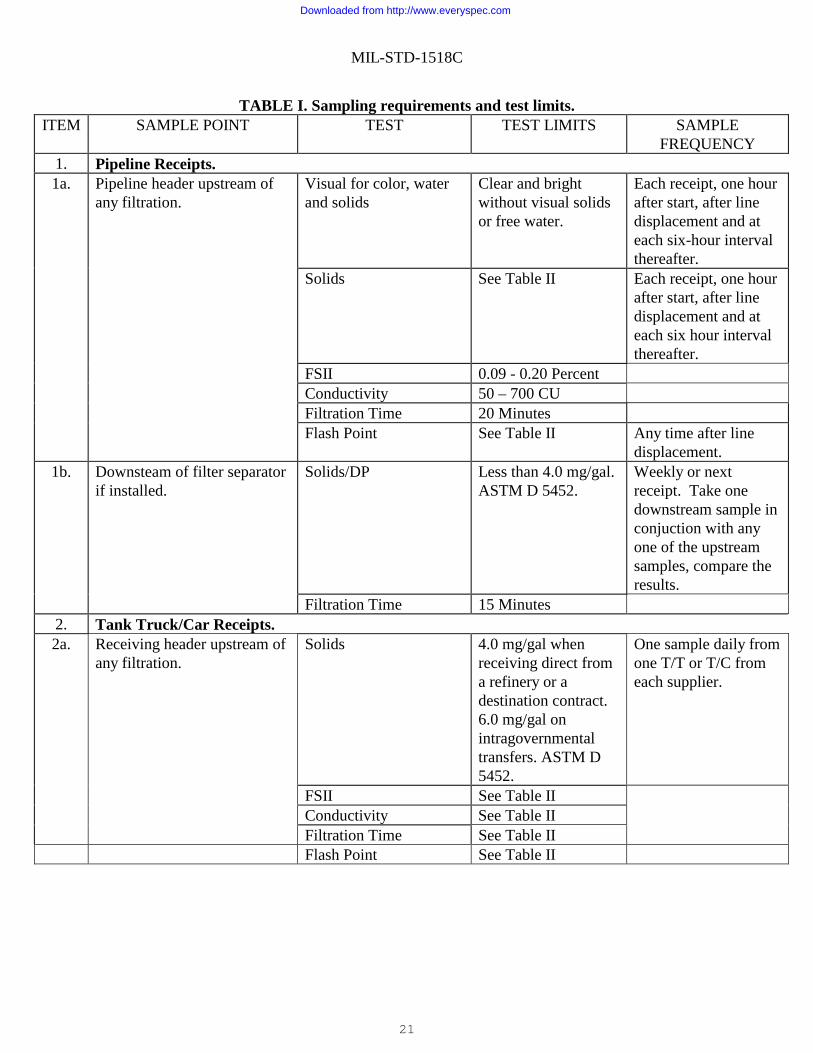
TABLE I. Sampling requirements and test limits.ITEM SAMPLE POINT TEST TEST LIMITS SAMPLE
FREQUENCY 1. Pipeline Receipts. 1a. Pipeline header upstream of
any filtration. Visual for color, water and solids
Clear and bright without visual solids or free water.
Each receipt, one hour after start, after line displacement and at each six-hour interval thereafter.
Solids See Table II Each receipt, one hour after start, after line displacement and at each six hour interval thereafter.
FSII 0.09 - 0.20 Percent Conductivity 50 – 700 CU Filtration Time 20 Minutes Flash Point See Table II Any time after line
displacement. 1b. Downsteam of filter separator
if installed. Solids/DP Less than 4.0 mg/gal.
ASTM D 5452. Weekly or next receipt. Take one downstream sample in conjuction with any one of the upstream samples, compare the results.
Filtration Time 15 Minutes 2. Tank Truck/Car Receipts. 2a. Receiving header upstream of
any filtration. Solids 4.0 mg/gal when
receiving direct from a refinery or a destination contract. 6.0 mg/gal on intragovernmental transfers. ASTM D 5452.
One sample daily from one T/T or T/C from each supplier.
FSII See Table II Conductivity See Table II Filtration Time See Table II Flash Point See Table II
Downloaded from http://www.everyspec.com
MIL-STD-1518C
22
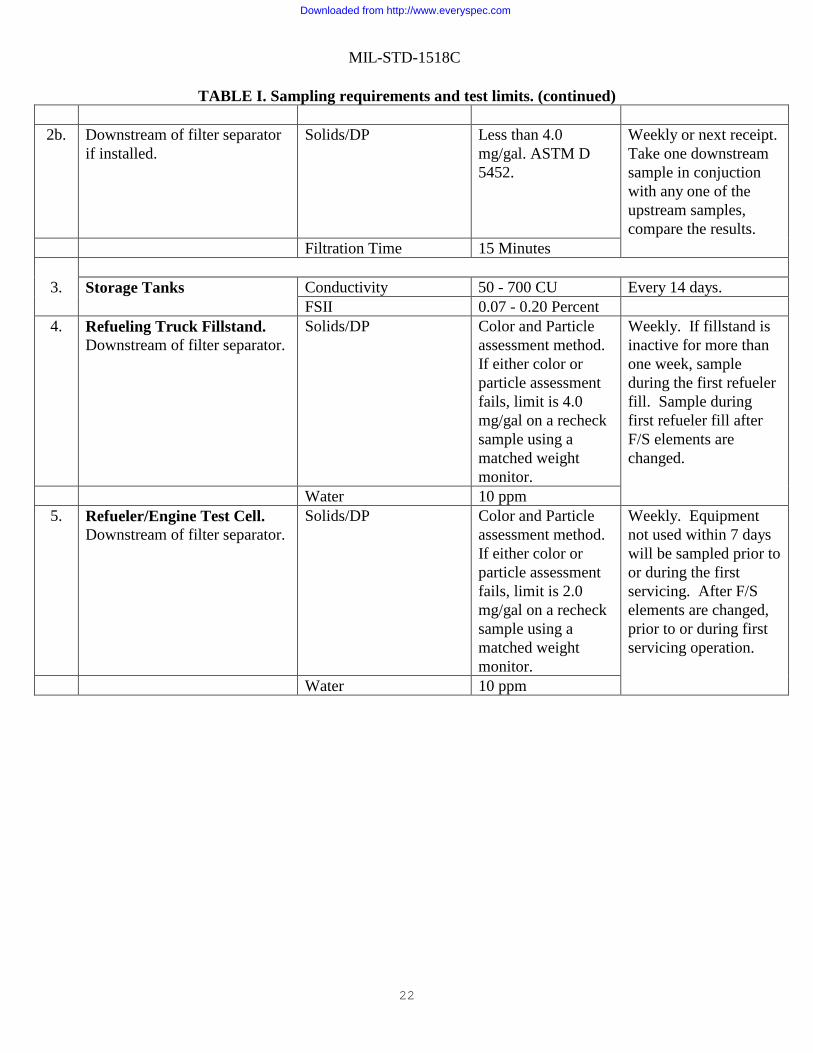
TABLE I. Sampling requirements and test limits. (continued)
2b. Downstream of filter separator if installed.
Solids/DP Less than 4.0 mg/gal. ASTM D 5452.
Weekly or next receipt. Take one downstream sample in conjuction with any one of the upstream samples, compare the results.
Filtration Time 15 Minutes
3. Storage Tanks Conductivity 50 - 700 CU Every 14 days. FSII 0.07 - 0.20 Percent
4. Refueling Truck Fillstand. Downstream of filter separator.
Solids/DP Color and Particle assessment method. If either color or particle assessment fails, limit is 4.0 mg/gal on a recheck sample using a matched weight monitor.
Weekly. If fillstand is inactive for more than one week, sample during the first refueler fill. Sample during first refueler fill after F/S elements are changed.
Water 10 ppm 5. Refueler/Engine Test Cell.
Downstream of filter separator. Solids/DP Color and Particle
assessment method. If either color or particle assessment fails, limit is 2.0 mg/gal on a recheck sample using a matched weight monitor.
Weekly. Equipment not used within 7 days will be sampled prior to or during the first servicing. After F/S elements are changed, prior to or during first servicing operation.
Water 10 ppm
Downloaded from http://www.everyspec.com
MIL-STD-1518C
23
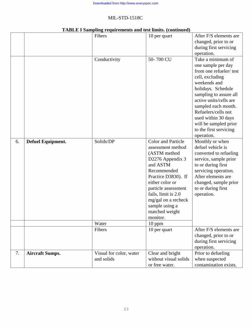
TABLE I Sampling requirements and test limits. (continued) Fibers 10 per quart After F/S elements are
changed, prior to or during first servicing operation.
Conductivity 50- 700 CU Take a minimum of one sample per day from one refueler/ test cell, excluding weekends and holidays. Schedule sampling to assure all active units/cells are sampled each month. Refuelers/cells not used within 30 days will be sampled prior to the first servicing operation.
6. Defuel Equipment. Solids/DP Color and Particle assessment method (ASTM method D2276 Appendix 3 and ASTM Recommended Practice D3830). If either color or particle assessment fails, limit is 2.0 mg/gal on a recheck sample using a matched weight monitor.
Monthly or when defuel vehicle is converted to refueling service, sample prior to or during first servicing operation. After elements are changed, sample prior to or during first operation.
Water 10 ppm Fibers 10 per quart After F/S elements are
changed, prior to or during first servicing operation.
7. Aircraft Sumps. Visual for color, water and solids
Clear and bright without visual solids or free water.
Prior to defueling when suspected contamination exists.
Downloaded from http://www.everyspec.com

MIL-STD-1518C
24
TABLE I. Sampling requirements and rest limits. (continued)
Solids Report solids in mg per
quart DO NOT convert weight to mg/gal. If the quantity of sample is less than one quart, report that quantity along with the total solids. Compare the membrane to the Millipore Membrane Particle Assessment Guide. If visual fails, determine the total solids. Limit is less than 4.0mg/qt. Both weight and visual must fail in order to consider the sample a failure. In the event of failure, analyze a one-quart recheck sample to verify results. If the retest passes visual assessment weighing the membrane is waived. If solid limits are exceeded, examine the membrane filter under a microscope to identify the types of contaminants and assist in pinpointing their source. Operators should gain knowledge through repeated use of the microscope. Examination of known particles will familiarize operators with what to look for on the filter.
Downloaded from http://www.everyspec.com
MIL-STD-1518C
25
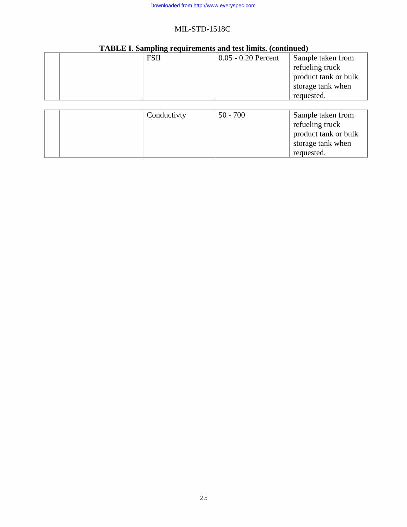
TABLE I. Sampling requirements and test limits. (continued)
FSII 0.05 - 0.20 Percent Sample taken from refueling truck product tank or bulk storage tank when requested.
Conductivty
50 - 700 Sample taken from
refueling truck product tank or bulk storage tank when requested.
Downloaded from http://www.everyspec.com
MIL-STD-1518C
26
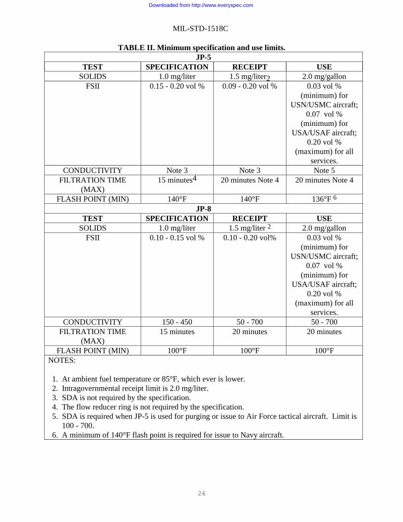
TABLE II. Minimum specification and use limits.JP-5
TEST SPECIFICATION RECEIPT USE SOLIDS 1.0 mg/liter 1.5 mg/liter2 2.0 mg/gallon
FSII 0.15 - 0.20 vol % 0.09 - 0.20 vol % 0.03 vol % (minimum) for
USN/USMC aircraft; 0.07 vol %
(minimum) for USA/USAF aircraft;
0.20 vol % (maximum) for all
services. CONDUCTIVITY Note 3 Note 3 Note 5
FILTRATION TIME (MAX)
15 minutes4 20 minutes Note 4 20 minutes Note 4
FLASH POINT (MIN) 140°F 140°F 136°F 6 JP-8
TEST SPECIFICATION RECEIPT USE SOLIDS 1.0 mg/liter 1.5 mg/liter 2 2.0 mg/gallon
FSII 0.10 - 0.15 vol % 0.10 - 0.20 vol% 0.03 vol % (minimum) for
USN/USMC aircraft; 0.07 vol %
(minimum) for USA/USAF aircraft;
0.20 vol % (maximum) for all
services. CONDUCTIVITY 150 - 450 50 - 700 50 - 700
FILTRATION TIME (MAX)
15 minutes 20 minutes 20 minutes
FLASH POINT (MIN) 100°F 100°F 100°F NOTES: 1. At ambient fuel temperature or 85°F, which ever is lower. 2. Intragovernmental receipt limit is 2.0 mg/liter. 3. SDA is not required by the specification. 4. The flow reducer ring is not required by the specification. 5. SDA is required when JP-5 is used for purging or issue to Air Force tactical aircraft. Limit is 100 - 700. 6. A minimum of 140°F flash point is required for issue to Navy aircraft.
Downloaded from http://www.everyspec.com
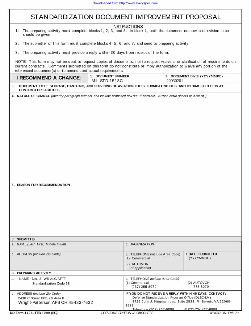
STANDARDIZ ATIO N DOCUM ENT IM PRO VEM ENT PRO PO SAL
INSTRUCTIO NS 1. Th e pre paring activity m ust com plete block s 1, 2, 3, and 8. In block 1, both th e docum ent num be r and revis ion lette r
s h ould be given. 2. Th e s ubm itte r of th is form m ust com plete block s 4, 5, 6, and 7, and s end to pre paring activity. 3. Th e pre paring activity m ust provide a re ply w ith in 30 days from re ce ipt of th e form . NO TE: Th is form m ay not be used to re q ue st copie s of docum ents , nor to re q ue st w aive rs , or clarification of re q uire m e nts on curre nt contracts . Com m ents subm itte d on th is form do not constitute or im ply auth orization to w aive any portion of th e re fe re nce d docum ent(s) or to am e nd contractual re q uire m e nts .
I RECO M M END A CH ANGE: 1. D OCUM ENT NUM BER M IL-STD -1518C
2. D OCUM ENT DATE (YYYYMMDD) 20030201
3. DOCUM ENT TITLE STO RAGE, H ANDLING, AND SERVICING O F AVIATIO N FUELS, LUBRICATING O ILS, AND H YDRAULIC FLUIDS AT CO NTRACTO R FACILITIES
4. NATURE O F CH ANGE (Ide ntify paragraph num be r and include propos e d re w rite , if possible . Attach e xtra s h e e ts as needed.)
5. REASO N FO R RECO M M ENDATIO N
6. SUBM ITTER a. NAM E (Last, First, M iddle Initial) b. ORGANIZ ATION
c. ADDRESS (Include Z ip Code ) d. TELEPH ONE (Include Are a Code ) (1) Com m e rcial (2) AUTOVON
(if applicable )
7.DATE SUBM ITTED (YYYYM M D D )
8. PREPARING ACTIVITY a. NAME D e t. 3, W R-ALC/AFTT Standardization Code 68
b. TELEPH ONE Include Are a Code ) (1) Com m e rcial (2) AUTOVON (9 37) 255-8070 785-8070
c. ADDRESS (Include Z ip Code ) 2430 C Stre e t Bldg 70 Are a B W righ t-Patte rson AFB O H 45433-7632
IF YOU DO NO T RECEIVE A REPLY W ITH IN 45 DAYS, CONTACT: D e fe nse Standardization Program Office (DLSC-LM ) 8725 Joh n J. K ingm an road, Suite 2533 Ft. Be lvoir, VA 22060-
2533 Te le ph one (703) 767-6888 AUTOVON 427-6888
DD Form 1426, FEB 19 9 9 (EG) PREVIO US EDITIO N IS O BSO LETE W H S/DIO R, Fe b 9 9
Downloaded from http://www.everyspec.com