NOS RTK TEAM FINAL REPORT - Home - NOAA Tides & Currents
27
NOS RTK TEAM FINAL REPORT August 31, 2000 Office of Coast Survey Center for Operational Oceanographic Products and Services Office of National Geodetic Survey Cary Wong (N/OPS1) Jack L. Riley (N/CS11) Doug Martin (N/OPS1) Lloyd C. Huff (N/CS1) Lucy Hall (N/NGS22) Stephen Gill (N/OPS) Rick Foote (N/NGS22) Edward Carlson (N/NGS2)
Transcript of NOS RTK TEAM FINAL REPORT - Home - NOAA Tides & Currents
NOS RTK TEAM FINAL REPORTAugust 31, 2000
Office of Coast SurveyCenter for Operational Oceanographic Products and Services
Office of National Geodetic Survey
Cary Wong (N/OPS1)Jack L. Riley (N/CS11)Doug Martin (N/OPS1)Lloyd C. Huff (N/CS1)Lucy Hall (N/NGS22)Stephen Gill (N/OPS)Rick Foote (N/NGS22)Edward Carlson (N/NGS2)
CONTENTS
PURPOSE . . . . . . . . . . . . . . . . . . . . . . . . . . . . . . . . . . . . . . . . . . . . . . . . . . . . . . . . . . . . . . . . . . . 1The RTK Team . . . . . . . . . . . . . . . . . . . . . . . . . . . . . . . . . . . . . . . . . . . . . . . . . . . . . . . . . 1
BACKGROUND . . . . . . . . . . . . . . . . . . . . . . . . . . . . . . . . . . . . . . . . . . . . . . . . . . . . . . . . . . . . . . 1Differential GPS . . . . . . . . . . . . . . . . . . . . . . . . . . . . . . . . . . . . . . . . . . . . . . . . . . . . . . . . . 1Kinematic GPS . . . . . . . . . . . . . . . . . . . . . . . . . . . . . . . . . . . . . . . . . . . . . . . . . . . . . . . . . . 2Real-Time and Post-Processed Kinematic GPS . . . . . . . . . . . . . . . . . . . . . . . . . . . . . . . . 2On-The-Fly Kinematic GPS . . . . . . . . . . . . . . . . . . . . . . . . . . . . . . . . . . . . . . . . . . . . . . . . 2Summary . . . . . . . . . . . . . . . . . . . . . . . . . . . . . . . . . . . . . . . . . . . . . . . . . . . . . . . . . . . . . . 3
NOS HYDROGRAPHIC SURVEY SPECIFICATIONS . . . . . . . . . . . . . . . . . . . . . . . . . . . . . . . 3Basic Minimum Criteria . . . . . . . . . . . . . . . . . . . . . . . . . . . . . . . . . . . . . . . . . . . . . . . . . . 3Horizontal and Vertical Accuracy Budget . . . . . . . . . . . . . . . . . . . . . . . . . . . . . . . . . . . . . 4
Maximum Allowable Horizontal Error for a Sounding . . . . . . . . . . . . . . . . . . . . . 4Maximum Allowable Vertical Error for a Sounding . . . . . . . . . . . . . . . . . . . . . . . 4
Kinematic GPS Horizontal and Vertical Accuracy Budget . . . . . . . . . . . . . . . . . . . . . . . . 5Relevant Dynamic Parameters in Vertical Measurement . . . . . . . . . . . . . . . . . . . 5Hydrographic Accuracy Requirements for Three-Dimensional GPS . . . . . . . . . . 6Chart Datum Issues . . . . . . . . . . . . . . . . . . . . . . . . . . . . . . . . . . . . . . . . . . . . . . . . 6
KINEMATIC GPS IN HYDROGRAPHY . . . . . . . . . . . . . . . . . . . . . . . . . . . . . . . . . . . . . . . . . . 7Operational Requirements (RTK, OTF RTK, or Post-Processed techniques?) . . . . . . . . . 7Survey Scenarios . . . . . . . . . . . . . . . . . . . . . . . . . . . . . . . . . . . . . . . . . . . . . . . . . . . . . . . . 7
Maximum Existing Water Level and GPS Control . . . . . . . . . . . . . . . . . . . . . . . . 8Mid-Level Water Level Datum and GPS Control . . . . . . . . . . . . . . . . . . . . . . . . . 9Mid-Level GPS and Inadequate Water Level Datum Control . . . . . . . . . . . . . . . . 9Inadequate GPS and Mid-Level Water Level Datum Control . . . . . . . . . . . . . . . . 9Inadequate GPS and Inadequate Water Level Datum Control . . . . . . . . . . . . . . . 10
Issues: Benefits & Costs . . . . . . . . . . . . . . . . . . . . . . . . . . . . . . . . . . . . . . . . . . . . . . . . . 10Inspiring Field Work . . . . . . . . . . . . . . . . . . . . . . . . . . . . . . . . . . . . . . . . . . . . . . . . . . . . 11
GPS Expedition to Tangier Island, Chesapeake Bay . . . . . . . . . . . . . . . . . . . . . . 11
RECOMMENDATIONS . . . . . . . . . . . . . . . . . . . . . . . . . . . . . . . . . . . . . . . . . . . . . . . . . . . . . . . 12
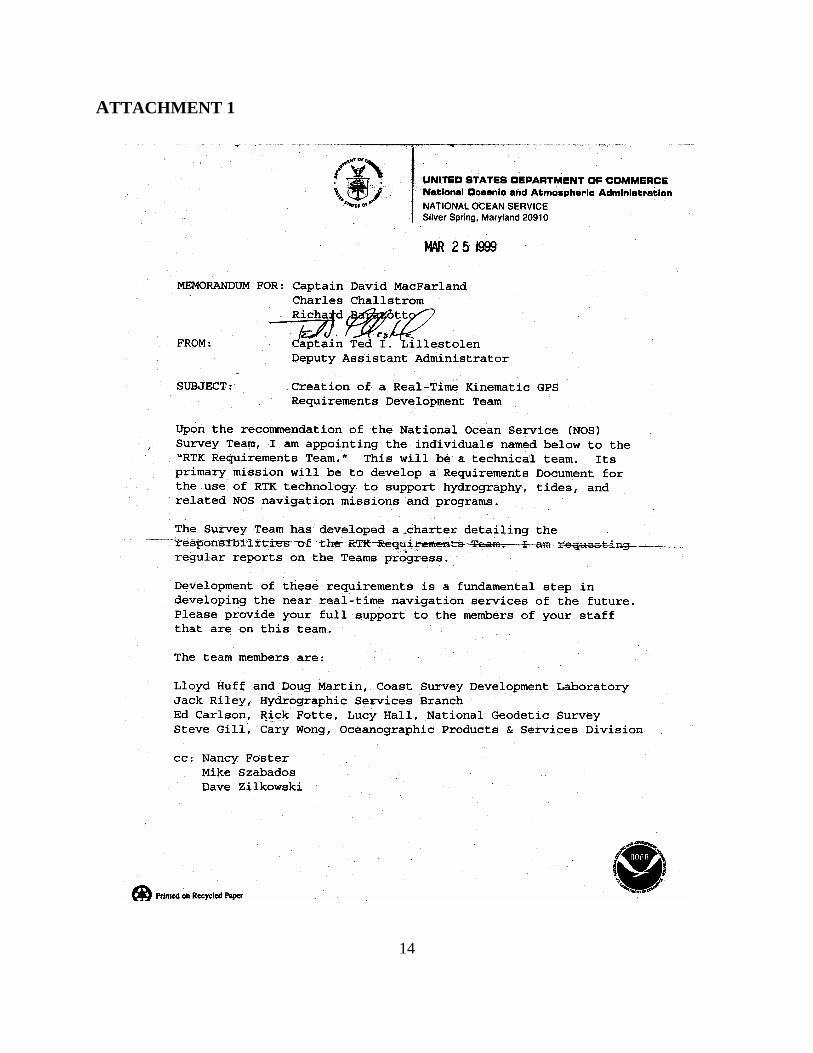
ATTACHMENT 1 – Memo Creating RTK Team . . . . . . . . . . . . . . . . . . . . . . . . . . . . . . . . . . . . 14
ATTACHMENT 2 – RTK Team Charter . . . . . . . . . . . . . . . . . . . . . . . . . . . . . . . . . . . . . . . . . . 15
APPENDIX A – Glossary of GPS Terms . . . . . . . . . . . . . . . . . . . . . . . . . . . . . . . . . . . . . . . . . . 16
APPENDIX B – Glossary of Tide Terms . . . . . . . . . . . . . . . . . . . . . . . . . . . . . . . . . . . . . . . . . . 20
BIBLIOGRAPHY . . . . . . . . . . . . . . . . . . . . . . . . . . . . . . . . . . . . . . . . . . . . . . . . . . . . . . . . . . . . 24
1
PURPOSE
The RTK TeamUpon the recommendation of the National Ocean Service (NOS) Survey Team, a Real-TimeKinematic (RTK) Requirements Team was created (see ATTACHMENT 1). The RTKRequirements Team (“the RTK Team”) was task to document requirements for the application ofRTK global positioning system (GPS) technology in support of hydrography, tides, and relatedNOS navigation missions and programs1. The NOS Survey team helped develop a charter for theRTK Team (see ATTACHMENT 2). The charter specifies that the purpose of the RTK Team isto “investigate and report on applications of RTK GPS to support [chart-quality hydrographicsurveying]”2. Here, chart-quality hydrographic surveying (“hydrography”) means meeting, orexceeding, applicable NOS hydrographic survey specifications3 and International HydrographicOrganization standards4. This is the final report of the RTK Team investigations into the use ofkinematic GPS methods for NOS hydrography.
BACKGROUND
To avoid possible confusion that may result from colloquial terminology, a short discussion ofGPS concepts is presented. A glossary of general GPS terms is found in APPENDIX A. Subsequent terms appearing in quotes or italics are contained in the glossary in one form oranother. Some general knowledge of GPS theory and technology is assumed.
Differential GPSThe term “differential GPS” (DGPS) encompasses a family of GPS relative positioningtechniques. DGPS uses two or more GPS receiver-antenna units to position an unknown point orset of points relative to a known point or set of points. DGPS improves upon the positioningaccuracy otherwise attainable in absolute point positioning methods, which use a single GPSreceiver-antenna unit.
For the purpose of our discussion, DGPS can be divided into two primary surveying categories: meter level and centimeter level. Meter-level DGPS surveys utilize GPS code phasemeasurements and are primarily based on the C/A code modulated on frequency L1; for example,a L1-only GPS receiver for the rover and (preferably) a L1/L2 base station. Centimeter-levelDGPS surveys utilize GPS carrier phase measurements and are based on the carrier signalpresent on both L1 and L2. There are many variations employed in both meter- and centimeter-level DGPS (e.g., meter-level DGPS augmented with carrier smoothing and carrier-aidedtracking, centimeter-level DGPS utilizing L1 only, etc.)5.
Meter-level DGPS has been used as the primary source of horizontal control for all NOShydrographic surveying operations in support of nautical charting since 19926. The United StatesCoast Guard (USCG) meter-level DGPS reference station network has been in operation foralmost as long7. Hydrographers and the general marine navigational community use the term
2
“DGPS” to refer to meter-level DGPS. Hereafter in our discussion, “DGPS” will refer to meter-level differential positioning based primarily on code phase measurements.
There are several forms of centimeter-level DGPS surveying and specific terms have beenadopted by the GPS community-at-large to differentiate between those techniques.
Kinematic GPSThe term “kinematic GPS” refers to the form of centimeter-level differential positioning which(primarily) uses carrier phase observables. Intuitively, “kinematic” GPS implies that differentialcorrections are formulated in conjunction with a mobile GPS receiver (i.e., a rover in conjunctionwith at least one static base station). Although many “static GPS” techniques also exist whichuse both code- and carrier-phases and are used in hydrography, we will focus discussion onmobile, kinematic GPS-based methods.
Real-Time and Post-Processed Kinematic GPSOperationally, the kinematic GPS solution can be determined either in real-time or after post-processing. “Real time” in the term “real-time kinematic GPS” (RTK GPS) simply refers to thefact that the carrier phase corrections are transmitted in real time via some (wireless) data link;e.g., via very-high frequency (VHF), HF, or ultra-HF (UHF) radio transmission–c.f., USCG real-time DGPS via HF radiobeacon. All post-processing techniques require the kinematic GPScarrier phase “observables” to be continuously recorded. Long, uninterrupted observationsessions could pose a data management problem. Post-processed kinematic GPS methods mightnot exist were it not for the complexity associated with real-time data links and the resolution ofthe carrier phase ambiguity in real time. Use of the GPS carrier phase permits resolution at themillimeter level, provided the ambiguity of the integer-number of carrier phase wavelengths canbe determined and maintained. Incorrect ambiguity resolution translates to a degradation ofpositioning accuracy and, depending on user accuracy requirements, the percentage of systemavailability.
On-The-Fly Kinematic GPSKinematic GPS technology is not new to NOS. Starting in 1983, NOS has developed centimeter-level kinematic GPS techniques to support land, air, and marine applications8. At first thesetechniques relied on some form of static initialization procedure to resolve carrier phaseambiguity. During static initialization, the kinematic GPS receivers are required to be stationaryfor some period of time after loss of satellite signal lock (e.g., after receiver power-up or recoveryfrom antenna signal interruption). In 1989 NOS extended kinematic GPS technology tocircumvent the static initialization requirement. Subsequently, carrier phase ambiguity could beresolved in the presence of relative motion between two GPS receiver-antenna units “on-the-fly”(OTF)9. Not to be confused with the operational term “real time”, OTF refers to themathematical technique that resolves GPS carrier phase integer ambiguities without requiring aGPS receiver to be stationary at any time. Indeed, OTF can be applied in real time during RTKGPS, or kinematic GPS data can be post-processed via OTF going either, or both, forward andreverse on the time line8. Because no GPS receiver can ever be completely immune to loss of
3
satellite signal lock the application of OTF is vital to the practical use of kinematic GPS inhydrography and any other mobile application.
The utility of OTF is currently being applied in kinematic GPS for hydrographic calibrationactivities within NOS Coast Survey (CS). CS has been employing post-processed kinematicGPS methods using OTF since 1993 in support of hydrography8,10. Consequently, the term“OTF” has become so commonplace in this regard that NOS hydrographers typically use it torefer to the specific concept of post-processed OTF kinematic GPS. NOS hydrographers usuallyspeak of “OTF” in referring to all kinematic GPS endeavors not computed in real time.
SummaryIn summary, the following GPS terminology is used in the NOS hydrographic community:
DGPS – Meter-level differential positioning based on code phase measurements
RTK GPS – Or simply “RTK”; centimeter-level (i.e., less-than-or-equal-to onedecimeter) differential positioning based on GPS carrier phasemeasurements transmitted in real time; static initialization may benecessary, but “OTF RTK” usually implied
OTF RTK – RTK GPS technique where static initialization is not necessary
Post-Processed OTF – Sometimes simply “OTF”; centimeter-level differential positioningbased on GPS carrier phase measurements computed off-line (i.e., not inreal time); and, static initialization is not necessary. The ability to post-process forward and reverse on the time line provides a means of dataquality assurance.
NOS HYDROGRAPHIC SURVEY SPECIFICATIONS
Concepts related to water level observations are discussed in this section. A glossary of someimportant tide terms is found in APPENDIX B. Subsequent water level terms appearing inquotes or italics are tabulated in the glossary. Some general knowledge in the theory of tides isassumed.
Basic Minimum CriteriaThe Hydrographic Surveys Division of the Office of Coast Survey document NOS HydrographicSurveys Specifications and Deliverables3 contains the minimum criteria for shallow-waterhydrographic surveys. These requirements are used by NOAA field units and by organizationsunder government contract to deliver data for application to the nautical charts produced byNOAA. The specifications detailed are based, in part, on the International HydrographicOrganization Standards for Hydrographic Surveys4. Additional details for specific project areas
4
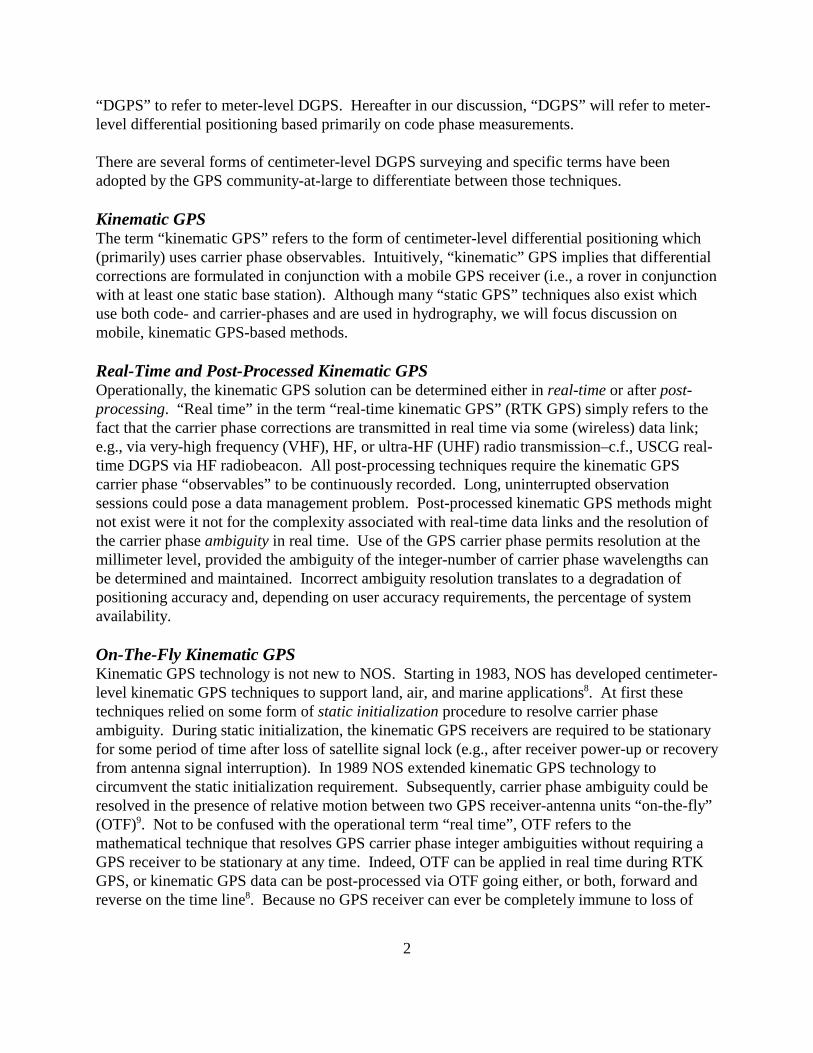
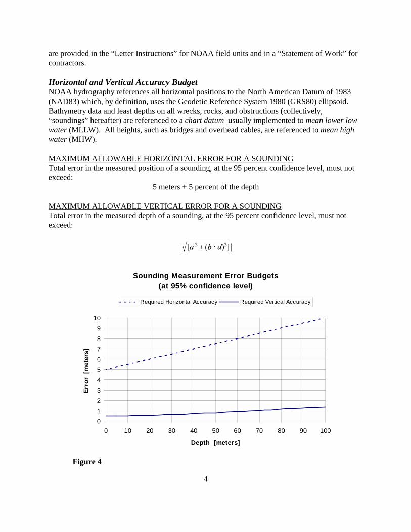
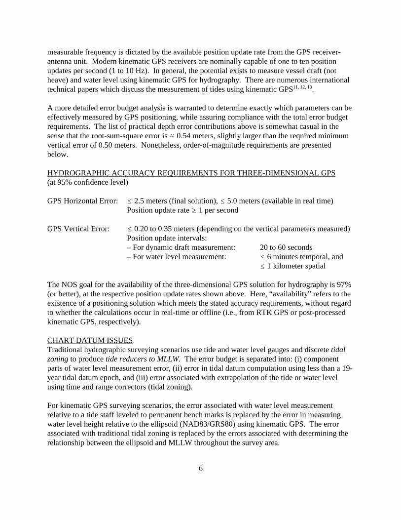
Sounding Measurement Error Budgets(at 95% confidence level)
0123456789
10
0 10 20 30 40 50 60 70 80 90 100
Depth [meters]
Erro
r [m
eter
s]
Required Horizontal Accuracy Required Vertical Accuracy
Figure 4
are provided in the “Letter Instructions” for NOAA field units and in a “Statement of Work” forcontractors.
Horizontal and Vertical Accuracy BudgetNOAA hydrography references all horizontal positions to the North American Datum of 1983(NAD83) which, by definition, uses the Geodetic Reference System 1980 (GRS80) ellipsoid. Bathymetry data and least depths on all wrecks, rocks, and obstructions (collectively,“soundings” hereafter) are referenced to a chart datum–usually implemented to mean lower lowwater (MLLW). All heights, such as bridges and overhead cables, are referenced to mean highwater (MHW).
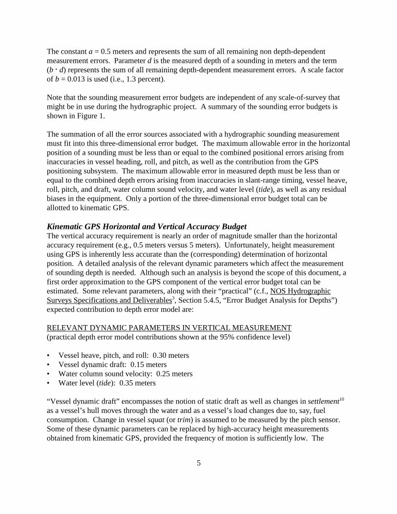
MAXIMUM ALLOWABLE HORIZONTAL ERROR FOR A SOUNDINGTotal error in the measured position of a sounding, at the 95 percent confidence level, must notexceed:
5 meters + 5 percent of the depth
MAXIMUM ALLOWABLE VERTICAL ERROR FOR A SOUNDINGTotal error in the measured depth of a sounding, at the 95 percent confidence level, must notexceed:
5
The constant a = 0.5 meters and represents the sum of all remaining non depth-dependentmeasurement errors. Parameter d is the measured depth of a sounding in meters and the term(b @ d) represents the sum of all remaining depth-dependent measurement errors. A scale factorof b = 0.013 is used (i.e., 1.3 percent).
Note that the sounding measurement error budgets are independent of any scale-of-survey thatmight be in use during the hydrographic project. A summary of the sounding error budgets isshown in Figure 1.
The summation of all the error sources associated with a hydrographic sounding measurementmust fit into this three-dimensional error budget. The maximum allowable error in the horizontalposition of a sounding must be less than or equal to the combined positional errors arising frominaccuracies in vessel heading, roll, and pitch, as well as the contribution from the GPSpositioning subsystem. The maximum allowable error in measured depth must be less than orequal to the combined depth errors arising from inaccuracies in slant-range timing, vessel heave,roll, pitch, and draft, water column sound velocity, and water level (tide), as well as any residualbiases in the equipment. Only a portion of the three-dimensional error budget total can beallotted to kinematic GPS.
Kinematic GPS Horizontal and Vertical Accuracy BudgetThe vertical accuracy requirement is nearly an order of magnitude smaller than the horizontalaccuracy requirement (e.g., 0.5 meters versus 5 meters). Unfortunately, height measurementusing GPS is inherently less accurate than the (corresponding) determination of horizontalposition. A detailed analysis of the relevant dynamic parameters which affect the measurementof sounding depth is needed. Although such an analysis is beyond the scope of this document, afirst order approximation to the GPS component of the vertical error budget total can beestimated. Some relevant parameters, along with their “practical” (c.f., NOS HydrographicSurveys Specifications and Deliverables3, Section 5.4.5, “Error Budget Analysis for Depths”)expected contribution to depth error model are:
RELEVANT DYNAMIC PARAMETERS IN VERTICAL MEASUREMENT(practical depth error model contributions shown at the 95% confidence level)
• Vessel heave, pitch, and roll: 0.30 meters• Vessel dynamic draft: 0.15 meters• Water column sound velocity: 0.25 meters• Water level (tide): 0.35 meters
“Vessel dynamic draft” encompasses the notion of static draft as well as changes in settlement10
as a vessel’s hull moves through the water and as a vessel’s load changes due to, say, fuelconsumption. Change in vessel squat (or trim) is assumed to be measured by the pitch sensor. Some of these dynamic parameters can be replaced by high-accuracy height measurementsobtained from kinematic GPS, provided the frequency of motion is sufficiently low. The
6
measurable frequency is dictated by the available position update rate from the GPS receiver-antenna unit. Modern kinematic GPS receivers are nominally capable of one to ten positionupdates per second (1 to 10 Hz). In general, the potential exists to measure vessel draft (notheave) and water level using kinematic GPS for hydrography. There are numerous internationaltechnical papers which discuss the measurement of tides using kinematic GPS11, 12, 13.
A more detailed error budget analysis is warranted to determine exactly which parameters can beeffectively measured by GPS positioning, while assuring compliance with the total error budgetrequirements. The list of practical depth error contributions above is somewhat casual in thesense that the root-sum-square error is . 0.54 meters, slightly larger than the required minimumvertical error of 0.50 meters. Nonetheless, order-of-magnitude requirements are presentedbelow.
HYDROGRAPHIC ACCURACY REQUIREMENTS FOR THREE-DIMENSIONAL GPS(at 95% confidence level)
GPS Horizontal Error: # 2.5 meters (final solution), # 5.0 meters (available in real time)Position update rate $ 1 per second
GPS Vertical Error: # 0.20 to 0.35 meters (depending on the vertical parameters measured)Position update intervals:– For dynamic draft measurement: 20 to 60 seconds– For water level measurement: # 6 minutes temporal, and
# 1 kilometer spatial
The NOS goal for the availability of the three-dimensional GPS solution for hydrography is 97%(or better), at the respective position update rates shown above. Here, “availability” refers to theexistence of a positioning solution which meets the stated accuracy requirements, without regardto whether the calculations occur in real-time or offline (i.e., from RTK GPS or post-processedkinematic GPS, respectively).
CHART DATUM ISSUESTraditional hydrographic surveying scenarios use tide and water level gauges and discrete tidalzoning to produce tide reducers to MLLW. The error budget is separated into: (i) componentparts of water level measurement error, (ii) error in tidal datum computation using less than a 19-year tidal datum epoch, and (iii) error associated with extrapolation of the tide or water levelusing time and range correctors (tidal zoning).
For kinematic GPS surveying scenarios, the error associated with water level measurementrelative to a tide staff leveled to permanent bench marks is replaced by the error in measuringwater level height relative to the ellipsoid (NAD83/GRS80) using kinematic GPS. The errorassociated with traditional tidal zoning is replaced by the errors associated with determining therelationship between the ellipsoid and MLLW throughout the survey area.
7
The MLLW datum relative to GPS must be determined in all scenarios. Tide gauges must beinstalled at “critical locations” wherein ellipsoidal height relationships are established byoccupying tidal benchmarks with GPS. This should be accomplished prior to actualhydrographic surveying operations. The error associated with tidal datum determination usingshort periods of observations (i.e., less than 19 years) will always exist as long as the chart datumis based on a tidal datum.
In summary, the kinematic GPS water level error budget would need to have estimates of:
• Errors of knowing OTF elevations of the water surface relative to the ellipsoid at the time andlocation of each sounding
• Errors of establishing or recovering MLLW/Ellipsoidal relationships at shore points usingappropriate combinations of new tide gauge measurements and datum determinations;benchmark and tidal datum recoveries from historical locations; and occupations of tidalbench marks with GPS to establish the relationships
• Errors in interpolating and extrapolating the MLLW/Ellipsoidal relationship using variousmeans such as interpolation, offshore GPS/tide gauge measurements, numerical estuarinemodels, and continuous zoning approaches such as “Tidal Constituent And ResidualInterpolation” (TCARI)14.
KINEMATIC GPS IN HYDROGRAPHY
Operational Requirements (RTK, OTF RTK, or Post-Processed techniques?)Strictly speaking a real-time, highly accurate and precise, 3-D position is not necessary forhydrographic surveying operations. Real-time horizontal positions need only to be good enoughto maintain survey line navigation (DGPS 5-meter horizontal accuracy sufficient for real time).
Vertical positioning is inherently an off line procedure in hydrography. Soundings are formed byreviewing and editing associated sensor data (i.e., vessel attitude and speed) as well as testing forpotentially anomalous depths, managing sound velocity profile data and performing speed andrefraction corrections, managing tide data and, finally, merging everything together into a verticalposition solution. Nominal post-processing time required to “clean & merge” soundings mightbe, at best, 1:1 as compared with acquisition time (1 hour of time on-line data acquisitionrequires 1 hour of off-line data processing). Hence, both real-time and post-processed kinematicGPS scenarios are feasible.
Survey ScenariosKinematic GPS requires an accurate horizontal and vertical reference frame in order to determinean accurate position on each sounding, relative to NAD83, and to determine an accurate depth ofeach sounding, relative to MLLW or other appropriate (local) chart datum (tide or water level;
8
e.g., Great Lakes).
The issue of determining separation between kinematic differential GPS vertical datum and thelocal chart datum is important to resolve for each survey area. These relationships may or maynot be well know. The complexity of the geodesy of the area, the tidal characteristics of the areaand the geographic complexity and size must be taken into account. Constant relationships maybe adequate in small areas; simple interpolation may be adequate in others; or complex spacialinterpolation may be required using numerical models and continuous zoning procedures (e.g.,TCARI14 and other tidal datum transformation models15).
Moored vessels or GPS buoys have been used by NOS, USACE, and organizations in Canada inseveral special projects for determining offshore tidal datums and their relationships to theellipsoid. Simultaneous tide measurements from offshore GPS platforms, with onshore controltide stations, have been successfully used to determine tidal datums and separation between chartdatum and the ellipsoid at offshore positions. This technique is operationally feasible for futuresurvey operations16.
There are a number of possible operational survey scenarios, depending on the availability ofsuitable horizontal and vertical control. The availability of control must be evaluated duringsurvey planning. Establishment of the appropriate control prior to survey operations (soundings)must become an integral part of the survey process. Establishment of the proper control for somesurvey areas may not be trivial and consequently may not be accomplished without considerableeffort and time.
The following is a list of some possible survey scenarios:
(1) MAXIMUM EXISTING WATER LEVEL AND GPS CONTROL
C The survey area contains NGS approved continuously-operating reference stations(CORS). For example, USCG, United States Army Corps of Engineers (USACE),Federal Aviation Administration (FAA), or International GPS Service for Geodynamics(IGS) CORS might be within a useable distance of the survey site.
C The survey area has a combination of operational NOS NWLON water level stations withknown chart datum relationships to ellipsoidal heights and/or historical water level stationlocations with a minimum of three bench marks with known up-to-date chart datumelevations relative to the ellipsoid.
C The relationship between local chart datum and the ellipsoid is known throughout thesurvey area with confidence based on interpolation techniques between the known shorelocations.
C Carrier phase corrections are broadcast or archived at a suitable epoch update for real-
9
time or post-processed kinematic GPS.
(2) MID-LEVEL WATER LEVEL DATUM AND GPS CONTROL
C The survey area has high accuracy reference network (HARN) marks, but there is nosuitable CORS station nearby. A GPS base station must be set up on one of the HARNmarks to record and/or broadcast the required carrier phase corrections to the surveyvessels.
C The survey area has a network of historical water level station locations with known up-to-date chart datum elevations on the bench marks. Some of the water level stationbenchmarks must be occupied temporarily with GPS to establish the chart-datum-to-ellipsoidal-height relationship.
C Some developmental (continuous or discrete zoning) work is required to determine thechart-datum-to-ellipsoidal-height relationship in offshore areas. Offshore GPS buoysmay be deployed and TCARI may be used to establish these relationships
(3) MID-LEVEL GPS AND INADEQUATE WATER LEVEL DATUM CONTROL
C The survey area has HARN marks but no operational or historical water level stationswith up-to-date chart datum elevations. A GPS base station must be set up on one of theHARN marks to record and/or broadcast the required carrier phase corrections to thesurvey vessels.
C Prior to collection of soundings, water level stations need to be established, chart datumelevation relative to the bench marks established and the bench marks occupied with GPSto establish the chart-datum-to-ellipsoidal-height relationships. Significant developmentwork may have to be done to extend the chart datum/ellipsoid height relationship over theentire survey area (depending on the particular tide regime and the geographic area).
(4) INADEQUATE GPS AND MID-LEVEL WATER LEVEL DATUM CONTROL
C The survey area has no CORS or HARN marks established but has an adequate networkof operating or historical water level stations with chart datum established. A GPS basestation will have to be established to record and/or broadcast carrier phase observablesduring survey operations.
C The water level station bench marks need to be occupied with GPS to establish the chart-datum-to-ellipsoid-height relationships and significant developmental work may have tobe done to determine the relationship throughout the survey area.
10
(5) INADEQUATE GPS AND INADEQUATE WATER LEVEL DATUM CONTROL
C Significant pre-operational survey field work must be done to establish the horizontal andvertical control necessary for the survey to be accomplished using kinematic GPS.
Obviously, there are numerous combinations of these situation elements that may exist in a givenhydrographic survey project area. The important point to note is that the complete situation mustbe identified early on in the project planning stages so that a ample time and resources can beorganized and mobilized to establish the vertical control necessary (prior to beginning surveyoperations). As noted in the above scenarios, this may entail conducting static GPS observationsto establish a control point for a base station or installing a water level measurement system toestablish a chart datum.
Although real-time solutions might appear to be the preferred operational scenario, it has beendemonstrated that NOS kinematic GPS hydrographic operations should not be limited to RTKalone. Scenarios based on post-processed kinematic GPS positioning may be the best approachin many instances.
Issues: Benefits & CostsWhen GPS control and chart datum are established prior to survey operations, the survey vesselscan accomplish their survey without the need to establish and monitor traditional tide and waterlevel gauges. The survey personnel may only need to construct a GPS base station if a CORSstation is not nearby. Pre-survey activities dealing with tide gauge and GPS control aretraditionally accomplished right at the beginning of surveys, but they could be scheduled andaccomplished much earlier in the project cycle. The potential benefit to be gained fromaccomplishing this earlier in the project cycle stems from the reduction in the time it takes toproduce “final” sounding data for a nautical chart product. That time would be reduced becausethe post-processing and application of tide data, tidal datums, and tidal zoning process wouldbecome streamlined. Soundings would be automatically referenced to chart datum in the courseof field data acquisition and processed on-board or during shore-based processing operations.
Both horizontal and vertical accuracy (vis-a-vis more accurate tide and dynamic draftmeasurements) could be increased in hydrographic surveying. Increased accuracy meanshydrographic surveying is organized for change as future, more-demanding charting requirementsarise. Hydrographic data accessible via electronic navigation charts will be commensurate withthe best capabilities of GPS marine navigation.
11
As in any satellite-based differential GPS positioning technique, the availability of kinematicGPS solutions (i.e. “fix” data) depends on four key issues17:
C Time to first fixC Recovery of data after an interruptionC Proximity of reference station(s) for computational purposesC Proximity of reference station(s) for purposes of radio data link coverage
The first three issues are intimately tied to the technical problem of acquiring and maintainingphase-lock in the carrier tracking loop of the kinematic GPS solution.
In the case of post-processed OTF, where forward and reverse kinematic GPS computations canbe compared, “NOS has found that GPS vertical positions of suitable accuracy are typicallyavailable only 85% of the time.”13. However, recent investigations by NOS have shown thathydrographic requirements for kinematic GPS availability are within reach, using a combinationof “carrier triple differences”, “code double differences”, and Kalman filtering13.
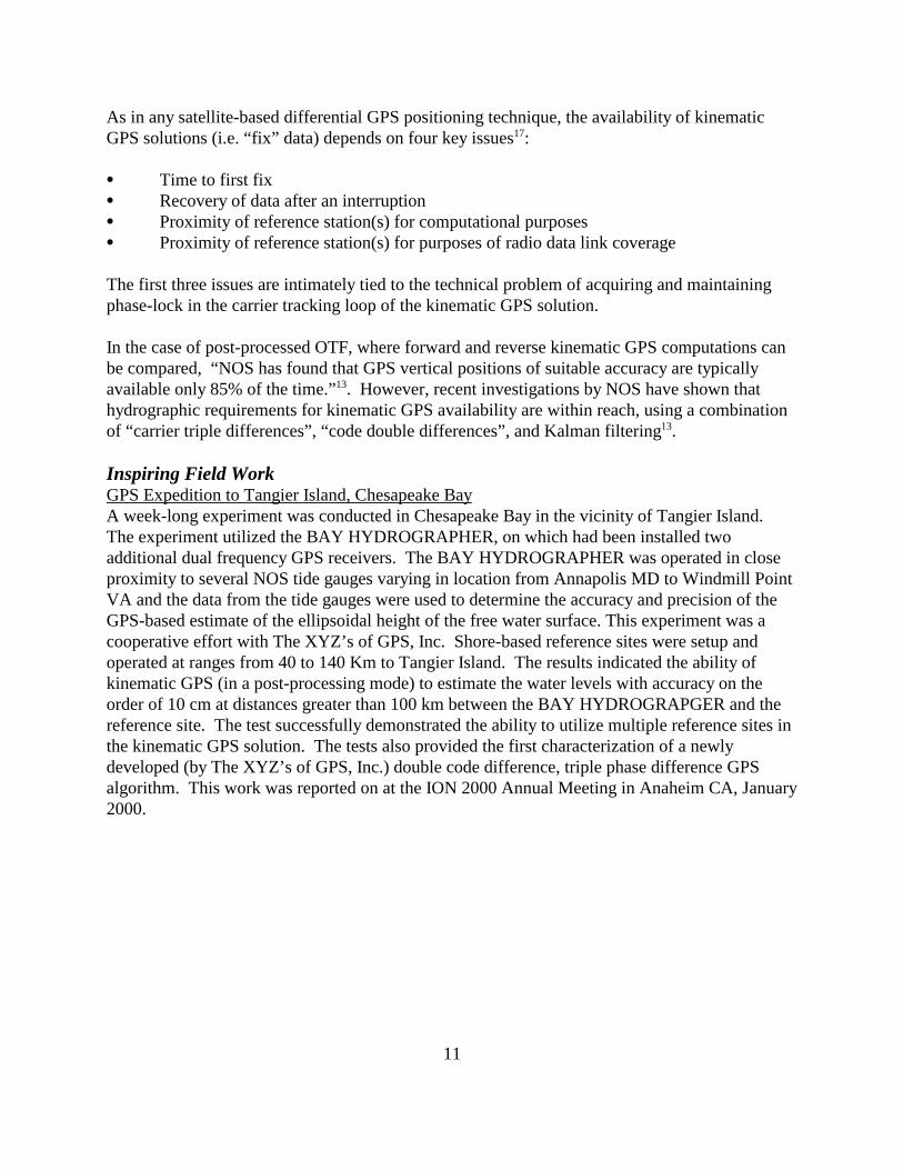
Inspiring Field WorkGPS Expedition to Tangier Island, Chesapeake BayA week-long experiment was conducted in Chesapeake Bay in the vicinity of Tangier Island. The experiment utilized the BAY HYDROGRAPHER, on which had been installed twoadditional dual frequency GPS receivers. The BAY HYDROGRAPHER was operated in closeproximity to several NOS tide gauges varying in location from Annapolis MD to Windmill PointVA and the data from the tide gauges were used to determine the accuracy and precision of theGPS-based estimate of the ellipsoidal height of the free water surface. This experiment was acooperative effort with The XYZ’s of GPS, Inc. Shore-based reference sites were setup andoperated at ranges from 40 to 140 Km to Tangier Island. The results indicated the ability ofkinematic GPS (in a post-processing mode) to estimate the water levels with accuracy on theorder of 10 cm at distances greater than 100 km between the BAY HYDROGRAPGER and thereference site. The test successfully demonstrated the ability to utilize multiple reference sites inthe kinematic GPS solution. The tests also provided the first characterization of a newlydeveloped (by The XYZ’s of GPS, Inc.) double code difference, triple phase difference GPSalgorithm. This work was reported on at the ION 2000 Annual Meeting in Anaheim CA, January2000.
12
RECOMMENDATIONS
This report represents preliminary efforts and findings based on considerable discussion andresearch by the RTK team. This report represents only the first phase of NOS moving towardsconducting hydrographic surveys using kinematic GPS. The Team has developed severalspecific recommendations based on what was learned in the process of preparing this report.
The Team recommends that:
1. A new crosscutting team of appropriate technical personnel should be established thatwill continue this effort in a formal manner. The new NOS RTK team should also have a"home" within a line office, possibly NGS, such that the line office is responsible forkeeping the momentum of the team going and takes ownership for its' success. ThroughNGS, the team could gain access to GPS hardware and expertise, as well as have a homebase that would be capable of providing R&D funding.
2. Starting immediately, all new GPS equipment (receivers and antennas) purchased forNOS hydrographic surveying should be dual frequency and either equipped for RTKoperations, or have an optional upgrade path to full RTK operations.
3. Greater use should be made of the BAY HYDROGRAPHER to field test operationalscenarios so that standard kinematic GPS operating procedures can be developed forhydrographic surveying.
4. Project instructions for NOS hydrographic surveys should be modified to include arequirement for the acquisition of GPS phase observables at one-second intervals on thesurvey platform and at one or more suitable shore sites. The observed data would beprovided to NGS or another designated group within NOS that would be tasked andfunded to process the data, to determine the time history of latitude, longitude, and Heightof the shipboard GPS antenna at one-second intervals, estimate the performance andinvestigate any problems encountered in the data processing.
5. Future Hydrographic Survey Contracts should be modified to require the acquisition ofGPS phase observables at one-second intervals on the survey platform and at one or moresuitable shore sites. An initial strategy may be to specify that both traditional surveyingprocedures and kinematic GPS procedures be employed as the contractor conducts patchtests. The phase observables would be processed, by the contractor in a post-missionmode, to determine the time history of Lat, Lon, and Height of the shipboard GPSantenna at one-second intervals. The observed data and the processed results wouldbecome deliverables under the contract. The observed data would be provided to NGS oranother designated group within NOS that would be tasked and funded to process thedata, to determine the time history of Lat, Lon, Height of the shipboard GPS antenna atone-second intervals, estimate the performance and investigate any problems encountered
13
in the data processing.
6. NOS should establish and/or nurture existing operational partnerships with the privateGPS industry. One possible means to accomplish this would be to continue to workcooperatively with the several developers and suppliers of GPS processing software toassess the reliability/ availability of solutions at different levels of accuracy and precision. The sets of GPS phase observables from shipboard antennas and relevant shore basedantennas, are available from the BAY HYDROGRAPHER, NOS hydrographic surveyplatforms, and Hydrographic Survey Contracts, could be used for algorithm testing.
7. The Joint Hydrographic Center partnership of NOAA with UNH should be encouraged toexplore GPS technology through applied research and operational testing for purposes ofimplementing kinematic GPS for NOS hydrographic surveying.
8. NOS should move quickly to determine ellipsoidal heights of MLLW for the US coastalwaters and to update MLLW to the current epoch. NOS should also continue to improvethe accuracy and spatial resolution of the geoid in the coastal waters of the US becauseuncertainties in the local geoid height and the ellipsoidal height of MLLW translatedirectly into uncertainties in elevations and depths relative to local MLLW.
9. NOS should plan for and provide adequate R&D funds to rapidly address new issues ofRTK-GPS as they are brought to light by the increased exposure associated withadditional field data and the attempts to establish practical field operating procedures.
10. The future RTK team or others in NOS should further investigate the issues ofpost-mission processing of RTK data as compared to true real-time operations. Issues tobe investigated include: (i) cost and complexity of real-time communication of GPSphase observables from the reference station to the moving platform, and (ii) impact ofpost-mission vs. real-time knowledge of the Lat, Lon, Height of a shipboard antenna onthe time required for the hydrographic field unit to process, review and forward ahydrographic survey data set.
11. NOS should anticipate that upon the decision to convert NOS hydrographic surveying toRTK-GPS, it may be necessary to purchase of a significant amount of RTG-GPSequipment in addition to that which was acquired by the ongoing slow purchase of suchequipment, as stated in recommendation (2), above.
14
ATTACHMENT 1
15
ATTACHMENT 2
16
APPENDIX A
A. Glossary of GPS terms (adapted from http://www.navtechgps.com/glossary.aspand http://www.analog.com/techsupt/prod_briefs/glossary.html)1. absolute positioning - mode in which a position is identified with respect
to a well-defined coordinate system, commonly a geocentric system (i.e., asystem whose point of origin coincides with the center of mass of theearth).
2. ambiguity - The initial bias in a carrier-phase observation of an arbitrarynumber of cycles. The initial phase measurement made when a GPSreceiver first locks onto a satellite signal is ambiguous by an integernumber of cycles since the receiver has no way of knowing when thecarrier wave left the satellite. This ambiguity remains constant as long asthe receiver remains locked onto the satellite signal and is resolved whenthe carrier-phase data are processed.
3. availability - The percentage of time that the services of a navigationsystem can be used within a particular coverage area. Signal availability isthe percentage of time that navigational signals transmitted from externalsources are available for use. Availability is a function of both the physicalcharacteristics of the operational environment and the technicalcapabilities of the transmitter facilities.
4. baseline - A baseline consists of a pair of stations for which simultaneousGPS data has been collected.
5. base Station - Also called a reference station. A receiver that is set up on aknown location specifically to collect data for differentially correctingrover files. The base station calculates the error for each satellite and,through differential correction, improves the accuracy of GPS positionscollected at unknown locations by a roving GPS receiver.
6. C/A code - The Coarse/Acquisition or Clear/Acquisition code modulatedinto the GPS L1 signal. This pseudo random noise (PRN) code is asequence of 1023 pseudo random binary biphase modulations on the GPScarrier at a chipping rate of 1.023 MHz, thus having a code repetitionperiod of 1 millisecond. The code was selected to provide good acquisitionproperties. Also known as the "civilian code." C/A codes are transmittedonly on the L1 frequency.
7. carrier - A radio wave having at least one characteristic (e.g. frequency,amplitude, phase) that can be varied from a known reference value bymodulation.
8. carrier-aided tracking - A signal processing strategy that uses the GPScarrier signal to achieve an exact lock on the pseudo random code.
9. carrier phase measurements - GPS measurements based on the L1 or L2carrier signal.
10. code phase GPS - GPS measurements based on the C/A code.
17
11. control point - Also called a control station. A monumented point towhich coordinates have been, or are being assigned by the use of surveyingobservations. The National Geodetic Survey maintains a nation-wide set ofcontrol points.
12. cycle slip - A discontinuity of an interger number of cycles in themeasured carrier beat phase resulting from a temporary loss-of-lock in thecarrier tracking loop of a GPS receiver.
13. differential positioning - Precise measurement of the relative positions oftwo or more receivers tracking the same GPS signals.
14. differential GPS (DGPS) - A technique used to improve positioning ornavigation accuracy by determining the positioning error at a knownlocation and subsequently incorporating a corrective factor (by real-timetransmission of correction or by post-processing) into the positioncalculations of another receiver operating in the same area andsimultaneously tracking the same satellites.
15. dilution of precision (DOP) - an indicator of satellite geometry for aunique constellation of satellites used to determine a position. Positionstagged with a higher DOP value generally constitute poorer measurementresults than those tagged with lower DOP.
16. distance root mean square (DRMS) - It is the root-mean-square value ofthe horizontal distance error. The root-mean-square value of the distancesfrom the true location point of the position fixes in a collection ofmeasurements. As typically used in GPS positioning, 2 drms is twice theroot mean square of error ellipse. This implies that the probability offinding the true horizontal position is within 95%.
17. elevation mask angle - That angle below which satellites should not betracked to avoid interference problems caused by buildings and trees andmultipath errors.
18. ellipsoid height - The measure of vertical distance above the ellipsoid.Not the same as elevation above sea level (or MLLW). A roving DGPSreceiver output position fix height in the same datum as the base DGPSreceiver.
19. epoch - Measurement interval or data frequency, as in makingobservations every one second (1 Hz).
20. geoid - The particular equipotential surface that coincides with mean sealevel and that may be imagined to extend through the continents. Thissurface is everywhere perpendicular to the force of gravity.
21. geoid height - The height above the geoid, often called elevation abovemean sea level.
22. ionosphere - The band of charged particles 80 to 120 miles above the
18
earth's surface, which represents a nonhomogeneous and dispersivemedium for radio signals.
23. ionospheric delay - A wave propagating through the ionosphereexperiences delay. Phase delay depends on electron content and affectscarrier signals. Group delay depends on dispersion in the ionosphere aswell, and affects signal modulation (codes). The phase and group delay areof the same magnitude but opposite sign.
24. ionospheric refraction - The change in the propagation speed of a signalas it passes through the ionosphere.
25. L-band - The group of radio frequencies extending from 390 MHz to1550 MHz. The GPS carrier frequencies L1 (15735 MHz) and L2 (1227.6MHz) are in the L-band.
26. local area DGPS (LADGPS) - A form of DGPS in which the user's GPSsystem receives real-time pseudorange and, possibly, carrier-phasecorrections from a reference receiver located within line of sight
27. multipath - Interference caused by reflected GPS signals arriving at thereceiver, typically as a result of nearby structures or other reflectivesurfaces. Signals travelling longer paths produce higher (erroneous)pseudorange estimates and, consequently, positioning errors.
28. on-the-fly (OTF) - The term used to identify a technique that resolvesdifferential carrier phase integer ambiguities without requiring a GPSreceiver to be stationary at any time.
29. P-code - The precise or precision code of the GPS signal, typically usedalone by US and allied military receivers. A very long sequence of pseudo-random binary biphase modulations on the GPS carrier at a chip rate of10.23 MHz which repeats about every 267 days. Each one-week segmentof this code is unique to one GPS satellite and is reset each week.
30. positional dilution of precision (PDOP) - Measure of the geometricalstrength of the GPS satellite configuration and translates into positionerror. For example, a 3 m error in the pseudoranges will translate into a 6m position error if the PDOP is 2.
31. phase lock - The technique whereby the phase of an oscillator signal ismade to follow exactly the phase of a reference signal. The receiver firstcompares the phases of the two signals, then uses the resulting phasedifference signal to adjust the reference oscillator frequency. Thiseliminates phase difference when the two signals are next compared.
32. post-processed differential GPS - In post-processed differential GPS thebase and roving recievers have no active data link between them. Instead,each records the satellite observations that will allow differentialcorrection at a later time. Differential correction software is used to
19
combine and process the data collected from these receivers.33. pseudo-range - A distance measurement based on the correlation of a
satellite transmitted code and the local receiver's reference code, that hasnot been corrected for errors in synchronization between the transmitter'sclock and the receiver's clock.
34. range rate - The rate of change between the satellite and receiver. Therange to a satellite changes due to satellite and observer motions. Rangerate is determined by measuring the Doppler shift of the satellite beaconcarrier.
35. real time kinematic (RTK) - The DGPS procedure whereby carrier phasecorrections are transmitted in real time from a reference station to theuser's roving receiver.
36. real-time differential GPS - A base station which computes, formats, andtransmits corrections usually through some sort of data link (e.g. VHFradio or cellular telephone) with each new GPS observation. The rovingunit requires some sort of data link receiving equipment to receive thetransmitted GPS corrections and get them into the GPS receiver so theycan be applied to its current observations.
37. relative positioning - The process of determining the relative difference inposition between two locations; in the case of GPS, by placing a receiverover each site and making simultaneous measurements observing the sameset of satellites at the same time. This technique allows the receiver tocancel errors that are common to both receivers, such as satellite clock andephemeris errors, propagation delays and so forth.
38. receiver independent exchange format (RINEX) - A set of standarddefinitions and formats that permits interchangeable use of GPS data fromdissimilar GPS receiver models or post processing software. The formatincludes definitions for time, phase and range.
39. RTCM SC-104 - The special committee of the Radio TechnicalCommission for Maritime Services that develops recommended standardsfor DGPS.
40. rover - Any mobile GPS receiver collecting data during a field session.The receiver's position can be computed relative to another, stationaryGPS receiver.
20
APPENDIX B
B. Glossary of tide terms (adapted from the NOS Tide and Current Glossary on theCO-OPS web site: http://www.co-ops.nos.noaa.gov/tideglos.html)1. accepted values - Tidal datums and Greenwich high and low water
intervals obtained through primary determination or simultaneousobservational comparisons made with a primary control tide station inorder to derive the equivalent of a 19-year value.
2. chart datum - The datum to which soundings on a chart are referred. It isusually taken to correspond to a low-water elevation, and its depressionbelow mean sea level is represented by the symbol Z . Since 1989, chartdatum has been implemented to mean lower low water for all marinewaters of the United States, its territories, Commonwealth of Puerto Rico,and Trust Territory of the Pacific Islands. See datum and National TidalDatum Convention of 1980.
3. datum (vertical) - For marine applications, a base elevation used as areference from which to reckon heights or depths. It is called a tidal datumwhen defined in terms of a certain phase of the tide. Tidal datums are localdatums and should not be extended into areas which have differinghydrographic characteristics without substantiating measurements. In orderthat they may be recovered when needed, such datums are referenced tofixed points known as bench marks. See chart datum.
4. mean high water (MHW) - A tidal datum. The average of all the highwater heights observed over the National Tidal Datum Epoch. For stationswith shorter series, simultaneous observational comparisons are made witha control tide station in order to derive the equivalent datum of theNational Tidal Datum Epoch.
5. mean lower low water (MLLW) - A tidal datum. The average of thelower low water height of each tidal day observed over the National TidalDatum Epoch. For stations with shorter series, simultaneous observationalcomparisons are made with a control tide station in order to derive theequivalent datum of the National Tidal Datum Epoch.
6. mean sea level (MSL) - A tidal datum. The arithmetic mean of hourlyheights observed over the National Tidal Datum Epoch. Shorter series arespecified in the name; e.g., monthly mean sea level and yearly mean sealevel.
7. national tidal datum epoch - The specific l9-year period adopted by theNational Ocean Service as the official time segment over which tideobservations are taken and reduced to obtain mean values (e.g., meanlower low water, etc.) for tidal datums. It is necessary for standardization
21
because of periodic and apparent secular trends in sea level. The presentNational Tidal Datum Epoch is 1960 through 1978. It is reviewed annuallyfor possible revision and must be actively considered for revision every 25years.
8. national water level observation network (NWLON) - The network oftide and water level stations operated by the National Ocean Service alongthe marine and Great Lakes coasts and islands of the United States. TheNWLON is composed of the primary and secondary control tide stationsof the National Ocean Service. Distributed along the coasts of the UnitedStates, this Network provides the basic tidal datums for coastal and marineboundaries and for chart datum of the United States. Tide observations at asecondary control tide station or tertiary tide station are reduced toequivalent l9-year tidal datums through the comparison of simultaneousobservations with a primary control tide station. In addition tohydrography and nautical charting, and to coastal and marine boundaries,the Network is used for coastal processes and tectonic studies, tsunami andstorm surge warnings, and climate monitoring. The National Water LevelObservation Network also includes stations operated throughout the GreatLakes Basin. The primary network is composed of 54 sites with 139seasonal gauge sites selectively operated 4 months annually for themaintenance of IGLD. The network supports regulation, navigation andcharting, river and harbor improvement, power generation, variousscientific activities, and the adjustment for vertical movement of theEarth's crust in the Great Lakes Basin.
9. primary control tide station - A tide station at which continuousobservations have been made over a minimum of 19 years. Its purpose isto provide data for computing accepted values of the harmonic and nonharmonic constants essential to tide predictions and to the determination oftidal datums for charting and for coastal and marine boundaries. The dataseries from this station serves as a primary control for the reduction ofrelatively short series from subordinate tide stations through the method ofcomparison of simultaneous observations and for monitoring long-periodsea level trends and variations. See tide station, secondary control tidestation, tertiary tide station, and subordinate tide station.
10. tertiary tide station - A tide station at which continuous observationshave been made over a minimum period of 30 days but less than 1 year.The series is reduced by comparison with simultaneous observations froma secondary control tide station. This station provides for a 29-dayharmonic analysis. See tide station, primary control tide station, secondarycontrol tide station, and subordinate tide station.
11. tidal zoning - The practice of dividing a hydrographic survey area intodiscrete zones or sections, each one possessing similar tidal characteristics.
22
One set of tide reducers is assigned to each zone. Tide reducers are used toadjust the soundings in that zone to chart datum (MLLW). Tidal zoning isnecessary in order to correct for differing water level heights occurringthroughout the survey area at any given time. Each zone of the survey areais geographically delineated such that the differences in time and range donot exceed certain limits, generally 0.2 hours and 0.2 feet respectively;however, these limits are subject to change depending upon type of survey,location, and tidal characteristics. The tide reducers are derived from thewater levels recorded at an appropriate tide station, usually nearby. Tidereducers are used to correct the soundings throughout the hydrographicsurvey area to a common, uniform, uninterrupted chart datum. See tidereducers.
12. tide - The periodic rise and fall of the water resulting from gravitationalinteractions between Sun, Moon, and Earth. The vertical component of theparticulate motion of a tidal wave. Although the accompanying horizontalmovement of the water is part of the same phenomenon, it is preferable todesignate this motion as tidal current. See tidal wave.
13. tide (water level) gauge - An instrument for measuring the rise and fall ofthe tide (water level). See ADR gauge, automatic tide gauge, NextGeneration Water Level Measurement System, gas purged pressure gauge,electric tape gauge, pressure gauge, and tide staff.
14. tide reducers - Height corrections for reducing soundings to chart datum(MLLW). A tide reducer represents the height of the water level at a givenplace and time relative to chart datum. Tide reducers are obtained fromone or more tide stations within or nearby the survey area. Often, due todiffering tidal characteristics over the survey area, the tide reducersobtained directly from a tide station must be corrected to adjust for timeand range of tide differences in the various zones of the hydrographicsurvey area. See tidal zoning.
15. tide (water level) station - The geographic location at which tidalobservations are conducted. Also, the facilities used to make tidalobservations. These may include a tide house, tide gauge, tide staff, andtidal bench marks. See primary control tide station, secondary control tidestation, tertiary tide station, and subordinate tide station.
16. type of tide - A classification based on characteristic forms of a tide curve.Qualitatively, when the two high waters and two low waters of each tidalday are approximately equal in height, the tide is said to be semidiurnal;when there is a relatively large diurnal inequality in the high or low watersor both, it is said to be mixed; and when there is only one high water andone low water in each tidal day, it is said to be diurnal. Quantitatively(after Dietrich), where the ratio of K1 + O1 to M2 + S2 is less than 0.25,the tide is classified as semidiurnal; where the ratio is from 0.25 to 1.5, the

23
tide is mixed, mainly semidiurnal; where the ratio is from 1.5 to 3.0, thetide is mixed, mainly diurnal; and where greater than 3.0, diurnal.
24
1. Lillestolen, Ted L., Captain, NOAA, Creation of a Real-Time Kinematic GPS RequirementsDevelopment Team, NOS memorandum, March 25, 1999.
2. Zilkoski, David, Charter for the Real-Time Kinematic GPS Team, April 8, 1999.
3. NOS Hydrographic Survey Specifications and Deliverables,http://chartmaker.ncd.noaa.gov/ocs/text/dsman2.pdf, Hydrographic Surveys Division, April 1999(subject to change).
4. International Hydrographic Organization Standards for Hydrographic Surveys, SpecialPublication 44, Fourth Ed., April 1998 (update expected in 2002).
5. Frodge, Sally L., Real-Time On-The-Fly Positioning Using the Global Positioning System,Draft Report, 1994.
6. Ferguson, Jeffrey A., Lieutenant, NOAA, DGPS in Nautical Charting Operations; A Reviewof the 1992 Field Season at the Coast and Geodetic Survey, Proceedings of ION GPS-92, Sept.16-18, 1992.
7. United States Coast Guard Navigation Center web page, DGPS section,http://www.navcen.uscg.mil/dgps/Default.htm.
8. Huff, Lloyd C. & Gallagher, Barry, On-the-fly GPS for Vertical Control of HydrographicSurveys, HYDRO ‘96, Session No. 4, Paper No. 19, seehttp://chartmaker.ncd.noaa.gov/csdl/htp/gps.html, Coast Survey Development Laboratory,Hydrogarphic Systems and Technology Programs.
9. Remondi, B. W., Real-Time Centimeter-Accuracy GPS for Marine Applications, Proceedingsof the Fifth Biennial NOS International Hydrographic Conference, Baltimore, MD, February 25-28, 1992.
10. Modern Measurement of Vessel Squat and Settlement using GPS,http://chartmaker.ncd.noaa.gov/csdl/htp/sas.html, Coast Survey Development Laboratory,Hydrographic Systems and Technology Programs.
11. Deloach, S.R., GPS Tides and Water Levels, HYDRO ‘96, Session No. 4, Paper No. 21, pp.211-219.
12. Shannon, B. F. & Martin, D. M., Kinematic GPS Observations to Establish a Mean LowerLow Water Dredging Datum Directly in a Navigation Channel, Proceedings of the ASPS/ACSMAnnual Convention, Vol. II, GIS and GPS, Baltimore, MD, April 1996.
BIBLIOGRAPHY
25
13. Huff, Lloyd C. & Remondi, Benjamin W., GPS Expedition to Tangier Island, ION 2000Annual Meeting, January 27, 2000.
14. Hess, Kurt, Tidal Constituent And Residual Interpolation (TCARI),http://chartmaker.ncd.noaa.gov/csdl/op/conzone.html, Coast Survey Development Laboratory,Marine Modeling and Analysis Programs.
15. Parsons, Stephen A. & O’Reilly, Charles T., The Application of GPS Derived EllipsoidalHeights to Hydrographic Data Acquisition and the Definition of Tidal Datums, GPSApplications, Canadian Hydrographic Conference 1998 (CHC 98), pp. 309-319.
16. Richards, Robert J. Jr. & Oswald, John, TIDAL ZONING of UPPER COOK INLET,ALASKA, 34th Annual Alaska Surveying and Mapping Conference, Anchorage, Alaska, February19, 1999.
17. Erceau, François, Across the English Channel with Long Range Kinematic, HydroINTERNATIONAL magazine, November/December 1998, Volume 2, Number 8, pp. 32-35.