North - Strathfield Council · 20. Permanent (non-structural) formwork shall be Lysaght's Bondek,...
7
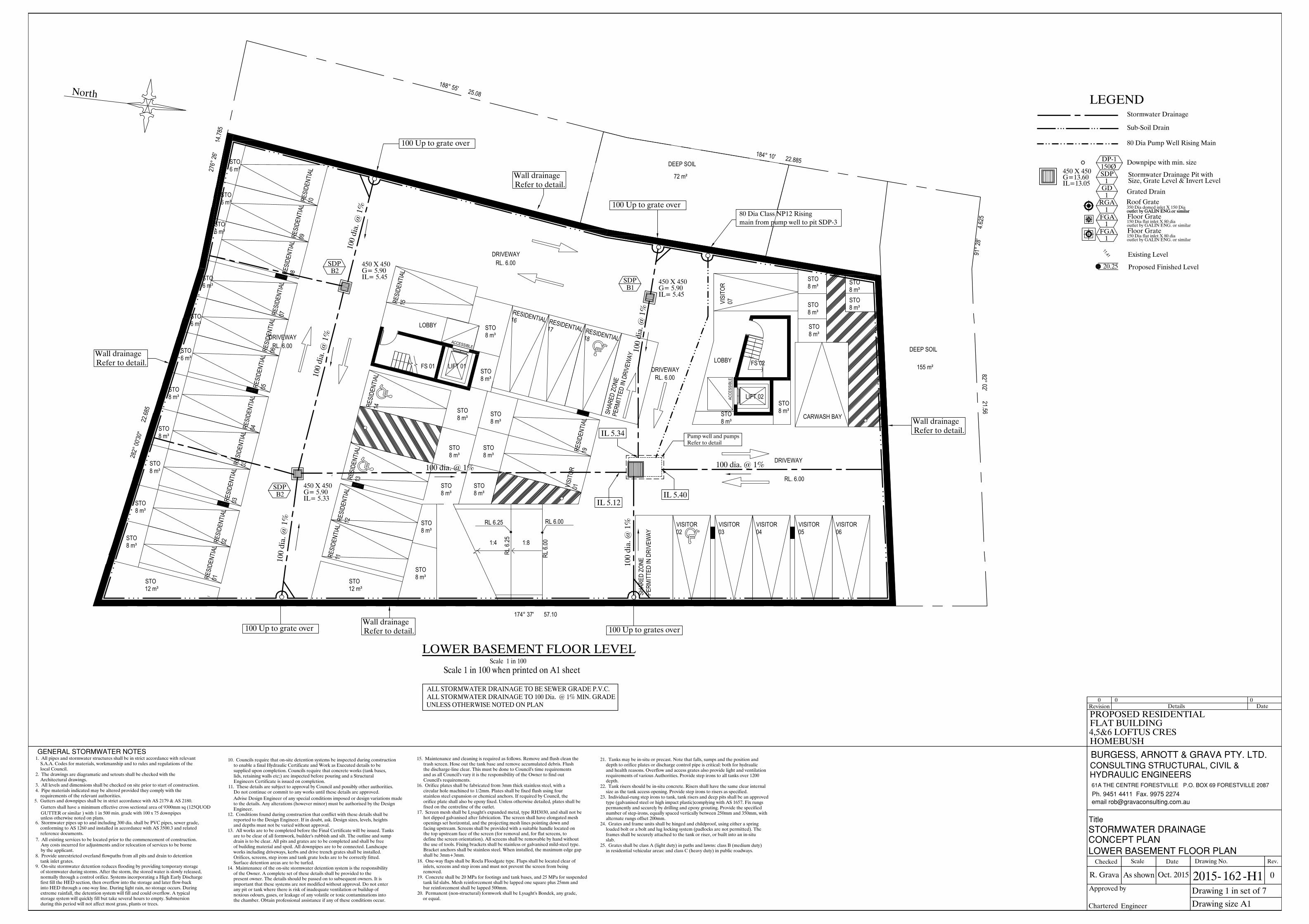
number of step-irons, equally spaced vertically between 250mm and 350mm, with alternate rungs offset 200mm. 24. Grates and frame units shall be hinged and childproof, using either a spring loaded bolt or a bolt and lug locking system (padlocks are not permitted). The frames shall be securely attached to the tank or riser, or built into an in-situ 25. Grates shall be class A (light duty) in paths and lawns: class B (medium duty) in residential vehicular areas: and class C (heavy duty) in public roadways. slab. the discharge-line clear. This must be done to Council's time requirements fixed on the centreline of the outlet. bar reinforcement shall be lapped 500mm. and as all Council's vary it is the responsibility of the Owner to find out 16. Orifice plates shall be fabricated from 3mm thick stainless steel, with a circular hole machined to 1/2mm. Plates shall be fixed flush using four stainless steel expansion or chemical anchors. If required by Council, the orifice plate shall also be epoxy fixed. Unless otherwise detailed, plates shall be 17. Screen mesh shall be Lysaght's expanded metal, type RH3030, and shall not be hot dipped galvanised after fabrication. The screen shall have elongated mesh openings set horizontal, and the projecting mesh lines pointing down and facing upstream. Screens shall be provided with a suitable handle located on the top upstream face of the screen (for removal and, for flat screens, to define the screen orientation). All screens shall be removable by hand without the use of tools. Fixing brackets shall be stainless or galvanised mild-steel type. Bracket anchors shall be stainless steel. When installed, the maximum edge gap 18. One-way flaps shall be Rocla Floodgate type. Flaps shall be located clear of inlets, screens and step irons and must not prevent the screen from being 19. Concrete shall be 20 MPa for footings and tank bases, and 25 MPa for suspended tank lid slabs. Mesh reinforcement shall be lapped one square plus 25mm and 20. Permanent (non-structural) formwork shall be Lysaght's Bondek, any grade, 21. Tanks may be in-situ or precast. Note that falls, sumps and the position and depth to orifice plates or discharge control pipe is critical: both for hydraulic and health reasons. Overflow and access grates also provide light and ventilation requirements of various Authorities. Provide step irons to all tanks over 1200 22. Tank risers should be in-situ concrete. Risers shall have the same clear internal size as the tank access opening. Provide step irons to risers as specified. 23. Individual-rung step irons to tank, tank risers and deep pits shall be an approved type (galvanised steel or high impact plastic)complying with AS 1657. Fix rungs permanently and securely by drilling and epoxy grouting. Provide the specified depth. removed. or equal. shall be 3mm+3mm. Council's requirements. during this period will not affect most grass, plants or trees. Engineers Certificate is issued on completion. and depths must not be varied without approval. Surface detention areas are to be turfed. first fill the HED section, then overflow into the storage and later flow-back into HED through a one-way line. During light rain, no storage occurs. During extreme rainfall, the detention system will fill and could overflow. A typical storage system will quickly fill but take several hours to empty. Submersion 10. Councils require that on-site detention systems be inspected during construction to enable a final Hydraulic Certificate and Work as Executed details to be supplied upon completion. Councils require that concrete works (tank bases, lids, retaining walls etc;) are inspected before pouring and a Structural 11. These details are subject to approval by Council and possibly other authorities. Do not continue or commit to any works until these details are approved. Advise Design Engineer of any special conditions imposed or design variations made to the details. Any alterations (however minor) must be authorised by the Design 12. Conditions found during construction that conflict with these details shall be reported to the Design Engineer. If in doubt, ask. Design sizes, levels, heights 13. All works are to be completed before the Final Certificate will be issued. Tanks are to be clear of all formwork, builder's rubbish and silt. The outline and sump drain is to be clear. All pits and grates are to be completed and shall be free of building material and spoil. All downpipes are to be connected. Landscape works including driveways, kerbs and drive trench grates shall be installed. Orifices, screens, step irons and tank grate locks are to be correctly fitted. 14. Maintenance of the on-site stormwater detention system is the responsibility of the Owner. A complete set of these details shall be provided to the present owner. The details should be passed on to subsequent owners. It is important that these systems are not modified without approval. Do not enter any pit or tank where there is risk of inadequate ventilation or buildup of noxious odours, gases, or leakage of any volatile or toxic contaminations into the chamber. Obtain professional assistance if any of these conditions occur. 15. Maintenance and cleaning is required as follows. Remove and flush clean the trash screen. Hose out the tank base and remove accumulated debris. Flush Engineer. requirements of the relevant authorities. 1. All pipes and stormwater structures shall be in strict accordance with relevant S.A.A. Codes for materials, workmanship and to rules and regulations of the 2. The drawings are diagramatic and setouts shall be checked with the 3. All levels and dimensions shall be checked on site prior to start of construction. 4. Pipe materials indicated may be altered provided they comply with the 6. Stormwater pipes up to and including 300 dia. shall be PVC pipes, sewer grade, conforming to AS 1260 and installed in accordance with AS 3500.3 and related 8. Provide unrestricted overland flowpaths from all pits and drain to detention 7. All existing services to be located prior to the commencement of construction. Any costs incurred for adjustments and/or relocation of services to be borne 9. On-site stormwater detention reduces flooding by providing temporary storage of stormwater during storms. After the storm, the stored water is slowly released, normally through a control orifice. Systems incorporating a High Early Discharge Architectural drawings. reference documents. tank inlet grates. by the applicant. )'0'4#. 5614/9#6'4 016'5 local Council. 5. Gutters and downpipes shall be in strict accordance with AS 2179 & AS 2180. Gutters shall have a minimum effective cross sectional area of 9300mm sq (125QUOD GUTTER or similar ) with 1 in 500 min. grade with 100 x 75 downpipes unless otherwise noted on plans. R. Grava 5614/9#6'4 &4#+0#)' Drawing size A1 Drawing No. Date Oct. 2015 As shown Scale Checked Drawing 1 in set of 7 Details Date 0 Engineer Chartered Approved by 2015- -H1 %10%'26 2.#0 162 Revision 0 0 Rev. 0 2J (CZ *;&4#7.+% '0)+0''45 # 6*' %'064' (14'568+..' 21 $1: (14'568+..' GOCKN TQD"ITCXCEQPUWNVKPIEQOCW $74)'55 #40166 )4#8# 26; .6& %1057.6+0) 5647%674#. %+8+. 6KVNG FLAT BUILDING 4,5&6 LOFTUS CRES PROPOSED RESIDENTIAL HOMEBUSH .19'4 $#5'/'06 (.114 2.#0 ACCESSIBLE ACCESSIBLE 1:8 1:4 PERMITTED IN DRIVEWAY SHARED ZONE PERMITTED IN DRIVEWAY SHARED ZONE RL 6.00 RL 6.25 LOBBY LOBBY LIFT 01 FS 01 FS 02 LIFT 02 Pñ STO Pñ STO Pñ STO Pñ STO Pñ STO Pñ STO Pñ STO Pñ STO Pñ STO Pñ STO Pñ STO Pñ STO Pñ STO Pñ STO Pñ STO Pñ STO Pñ STO Pñ STO Pñ STO Pñ STO Pñ STO Pñ STO Pñ STO Pñ STO Pñ STO Pñ STO Pñ STO Pñ STO Pñ STO Pñ STO 01 RESIDENTIAL 02 RESIDENTIAL 03 RESIDENTIAL 03 RESIDENTIAL 04 RESIDENTIAL 05 RESIDENTIAL 06 RESIDENTIAL 07 RESIDENTIAL 08 RESIDENTIAL 09 RESIDENTIAL 10 RESIDENTIAL 11 RESIDENTIAL 12 RESIDENTIAL 13 RESIDENTIAL 14 RESIDENTIAL 15 RESIDENTIAL 19 RESIDENTIAL 01 VISITOR 16 RESIDENTIAL 17 RESIDENTIAL 18 RESIDENTIAL 02 VISITOR 03 VISITOR 04 VISITOR 05 VISITOR 06 VISITOR 07 VISITOR CARWASH BAY DRIVEWAY DRIVEWAY DRIVEWAY DRIVEWAY RL. 6.00 RL. 6.00 RL. 6.00 RL. 6.00 RL 6.25 RL 6.00 LOWER BASEMENT FLOOR LEVEL DEEP SOIL Pð North 100 Up to grates over 100 Up to grate over 100 Up to grate over 100 Up to grate over Pump well and pumps Refer to detail 100 dia. @ 1% 450 X 450 G= 5.90 IL= 5.45 SDP B1 450 X 450 G= 5.90 IL= 5.45 450 X 450 G= 5.90 IL= 5.33 SDP B2 SDP B2 100 dia. @ 1% IL 5.12 IL 5.40 IL 5.34 100 dia. @ 1% 100 dia. @ 1% 100 dia. @ 1% 100 dia. @ 1% 100 dia. @ 1% Wall drainage Refer to detail. Wall drainage Refer to detail. Wall drainage Refer to detail. Wall drainage Refer to detail. main from pump well to pit SDP-3 80 Dia Class NP12 Rising Downpipe with min. size Stormwater Drainage Pit with Size, Grate Level & Invert Level 1 SDP IL=13.05 G=13.60 450 X 450 1 Grated Drain GD 1 RGA Roof Grate outlet by GALIN ENG.or similar 350 Dia domed inlet X 150 Dia outlet by GALIN ENG.or similar DP-1 1 FGA Floor Grate 150 Dia flat inlet X 80 dia outlet by GALIN ENG. or similar 1 FGA Floor Grate 150 Dia flat inlet X 80 dia outlet by GALIN ENG. or similar Stormwater Drainage Sub-Soil Drain LEGEND 80 Dia Pump Well Rising Main Proposed Finished Level Existing Level 20.25 11.41 DEEP SOIL Pð
Transcript of North - Strathfield Council · 20. Permanent (non-structural) formwork shall be Lysaght's Bondek,...
number of step-irons, equally spaced vertically between 250mm and 350mm, with alternate rungs offset 200mm.24. Grates and frame units shall be hinged and childproof, using either a spring loaded bolt or a bolt and lug locking system (padlocks are not permitted). The frames shall be securely attached to the tank or riser, or built into an in-situ
25. Grates shall be class A (light duty) in paths and lawns: class B (medium duty) in residential vehicular areas: and class C (heavy duty) in public roadways.
slab.
the discharge-line clear. This must be done to Council's time requirements
fixed on the centreline of the outlet.
bar reinforcement shall be lapped 500mm.
and as all Council's vary it is the responsibility of the Owner to find out
16. Orifice plates shall be fabricated from 3mm thick stainless steel, with a circular hole machined to 1/2mm. Plates shall be fixed flush using four stainless steel expansion or chemical anchors. If required by Council, the orifice plate shall also be epoxy fixed. Unless otherwise detailed, plates shall be
17. Screen mesh shall be Lysaght's expanded metal, type RH3030, and shall not be hot dipped galvanised after fabrication. The screen shall have elongated mesh openings set horizontal, and the projecting mesh lines pointing down and facing upstream. Screens shall be provided with a suitable handle located on the top upstream face of the screen (for removal and, for flat screens, to define the screen orientation). All screens shall be removable by hand without the use of tools. Fixing brackets shall be stainless or galvanised mild-steel type. Bracket anchors shall be stainless steel. When installed, the maximum edge gap
18. One-way flaps shall be Rocla Floodgate type. Flaps shall be located clear of inlets, screens and step irons and must not prevent the screen from being
19. Concrete shall be 20 MPa for footings and tank bases, and 25 MPa for suspended tank lid slabs. Mesh reinforcement shall be lapped one square plus 25mm and
20. Permanent (non-structural) formwork shall be Lysaght's Bondek, any grade,
21. Tanks may be in-situ or precast. Note that falls, sumps and the position and depth to orifice plates or discharge control pipe is critical: both for hydraulic and health reasons. Overflow and access grates also provide light and ventilation requirements of various Authorities. Provide step irons to all tanks over 1200
22. Tank risers should be in-situ concrete. Risers shall have the same clear internal size as the tank access opening. Provide step irons to risers as specified.23. Individual-rung step irons to tank, tank risers and deep pits shall be an approved type (galvanised steel or high impact plastic)complying with AS 1657. Fix rungs permanently and securely by drilling and epoxy grouting. Provide the specified
depth.
removed.
or equal.
shall be 3mm+3mm.
Council's requirements.
during this period will not affect most grass, plants or trees.
Engineers Certificate is issued on completion.
and depths must not be varied without approval.
Surface detention areas are to be turfed.
first fill the HED section, then overflow into the storage and later flow-back into HED through a one-way line. During light rain, no storage occurs. During extreme rainfall, the detention system will fill and could overflow. A typical storage system will quickly fill but take several hours to empty. Submersion
10. Councils require that on-site detention systems be inspected during construction to enable a final Hydraulic Certificate and Work as Executed details to be supplied upon completion. Councils require that concrete works (tank bases, lids, retaining walls etc;) are inspected before pouring and a Structural
11. These details are subject to approval by Council and possibly other authorities. Do not continue or commit to any works until these details are approved. Advise Design Engineer of any special conditions imposed or design variations made to the details. Any alterations (however minor) must be authorised by the Design
12. Conditions found during construction that conflict with these details shall be reported to the Design Engineer. If in doubt, ask. Design sizes, levels, heights
13. All works are to be completed before the Final Certificate will be issued. Tanks are to be clear of all formwork, builder's rubbish and silt. The outline and sump drain is to be clear. All pits and grates are to be completed and shall be free of building material and spoil. All downpipes are to be connected. Landscape works including driveways, kerbs and drive trench grates shall be installed. Orifices, screens, step irons and tank grate locks are to be correctly fitted.
14. Maintenance of the on-site stormwater detention system is the responsibility of the Owner. A complete set of these details shall be provided to the present owner. The details should be passed on to subsequent owners. It is important that these systems are not modified without approval. Do not enter any pit or tank where there is risk of inadequate ventilation or buildup of noxious odours, gases, or leakage of any volatile or toxic contaminations into the chamber. Obtain professional assistance if any of these conditions occur.
15. Maintenance and cleaning is required as follows. Remove and flush clean the trash screen. Hose out the tank base and remove accumulated debris. Flush
Engineer.
requirements of the relevant authorities.
1. All pipes and stormwater structures shall be in strict accordance with relevant S.A.A. Codes for materials, workmanship and to rules and regulations of the
2. The drawings are diagramatic and setouts shall be checked with the
3. All levels and dimensions shall be checked on site prior to start of construction.4. Pipe materials indicated may be altered provided they comply with the
6. Stormwater pipes up to and including 300 dia. shall be PVC pipes, sewer grade, conforming to AS 1260 and installed in accordance with AS 3500.3 and related
8. Provide unrestricted overland flowpaths from all pits and drain to detention
7. All existing services to be located prior to the commencement of construction. Any costs incurred for adjustments and/or relocation of services to be borne
9. On-site stormwater detention reduces flooding by providing temporary storage of stormwater during storms. After the storm, the stored water is slowly released, normally through a control orifice. Systems incorporating a High Early Discharge
Architectural drawings.
reference documents.
tank inlet grates.
by the applicant.
local Council.
5. Gutters and downpipes shall be in strict accordance with AS 2179 & AS 2180. Gutters shall have a minimum effective cross sectional area of 9300mm sq (125QUOD GUTTER or similar ) with 1 in 500 min. grade with 100 x 75 downpipesunless otherwise noted on plans.
R. Grava
Drawing size A1
Drawing No.Date
Oct. 2015As shown
ScaleChecked
Drawing 1 in set of 7
Details Date0
EngineerChartered
Approved by
2015- -H1
162
Revision00
Rev.
0
FLAT BUILDING4,5&6 LOFTUS CRES
PROPOSED RESIDENTIAL
HOMEBUSH
ACCE
SSIB
LE
ACCESSIBLE
1:81:4
PERM
ITTE
D IN
DRI
VEW
AY
SHAR
ED Z
ONE
PERM
ITTE
D IN
DRI
VEW
AYSH
ARED
ZON
E
RL 6.00RL 6.25
LOBBY
LOBBYLIFT 01FS 01 FS 02
LIFT 02
8 m³STO
8 m³STO
8 m³STO
8 m³STO8 m³STO
8 m³STO
8 m³STO
8 m³STO
8 m³STO
8 m³STO8 m³
STO
8 m³STO
8 m³STO
8 m³STO
8 m³STO
8 m³STO
8 m³STO
12 m³STO
8 m³STO
8 m³STO
8 m³STO
8 m³STO
8 m³STO
6 m³STO
6 m³STO
6 m³STO
6 m³STO
6 m³STO
6 m³STO
12 m³STO 01RE
SIDE
NTIA
L 02RESI
DENT
IAL
03RESI
DENT
IAL
03RESI
DENT
IAL 04RE
SIDE
NTIA
L05RE
SIDE
NTIA
L 06RESI
DENT
IAL 07RE
SIDE
NTIA
L08RE
SIDE
NTIA
L 09RESI
DENT
IAL 10RE
SIDE
NTIA
L
11RESI
DENT
IAL 12RE
SIDE
NTIA
L13RE
SIDE
NTIA
L
14RESI
DENT
IAL
15RESI
DENT
IAL
19RESI
DENT
IAL
01VISI
TOR
16RESIDENTIAL
17RESIDENTIAL
18RESIDENTIAL
02VISITOR
03VISITOR
04VISITOR
05VISITOR
06VISITOR
07VISI
TOR
CARWASH BAY
DRIVEWAY
DRIVEWAY
DRIVEWAY
DRIVEWAY
RL. 6.00
RL. 6.00
RL. 6.00
RL. 6.00
RL 6.
25
RL 6.
00
LOWER BASEMENT FLOOR LEVEL
DEEP SOIL
72 m²
188° 55' 25.08
184° 10' 22.885
91° 28' 4.625
82° 02' 21.56
174° 37' 57.10
282° 00'30" 22.685
276° 26' 14.785
North
100 Up to grates over
100 Up to grate over
100 Up to grate over
100 Up to grate over
Pump well and pumps Refer to detail
100
dia.
@ 1
%
450 X 450G= 5.90IL= 5.45
SDPB1
450 X 450G= 5.90IL= 5.45
450 X 450G= 5.90IL= 5.33
SDPB2
SDPB2
100 dia. @ 1%
IL 5.12IL 5.40
IL 5.34
100 dia. @ 1%
100
dia.
@ 1
%
100
dia.
@ 1
%
100
dia.
@ 1
%
100
dia.
@ 1
%
Wall drainageRefer to detail.
Wall drainageRefer to detail.
Wall drainageRefer to detail.
Wall drainageRefer to detail.
main from pump well to pit SDP-380 Dia Class NP12 Rising
Downpipe with min. size
Stormwater Drainage Pit withSize, Grate Level & Invert Level1
SDPIL=13.05G=13.60450 X 450
1 Grated DrainGD
1RGA Roof Grate
outlet by GALIN ENG.or similar350 Dia domed inlet X 150 Dia outlet by GALIN ENG.or similar
DP-1150Ø
1FGA Floor Grate
150 Dia flat inlet X 80 diaoutlet by GALIN ENG. or similar
1FGA Floor Grate
150 Dia flat inlet X 80 diaoutlet by GALIN ENG. or similar
Stormwater Drainage
Sub-Soil Drain
LEGEND
80 Dia Pump Well Rising Main
Proposed Finished Level
Existing Level
20.25
11.41
DEEP SOIL
155 m²

R. Grava
Drawing size A1
Drawing No.Date
Oct. 2015As shown
ScaleChecked
Drawing 2 in set of 7
Details Date0
EngineerChartered
Approved by
2015- -H2
162
Revision00
Rev.
0
FLAT BUILDING4,5&6 LOFTUS CRES
PROPOSED RESIDENTIAL
HOMEBUSH
ACCE
SSIB
LE
ACCESSIBLE
WASTE
1:81:41:8 1:4
WASTE
8 m³STO
SHARED ZONE
PERM
ITTE
D IN
DRI
VEW
AYSH
ARED
ZON
E
LOBBY
SHAR
ED Z
ONELIFT 01
FS 01FS 02
LIFT 02
8 m³STO
8 m³STO8 m³STO8 m³STO
8 m³STO
8 m³STO
8 m³STO
8 m³STO8 m³
STO
8 m³STO
8 m³STO8 m³
STO8 m³STO
12 m³STO
12 m³STO
6 m³STO
6 m³STO
6 m³STO
6 m³STO
6 m³STO
6 m³STO
6 m³STO
6 m³STO
ROOMSPRINKLER VALVE
PUMP ROOM +
FIRE HYDRANT20RE
SIDE
NTIA
L 21RESI
DENT
IAL
22RESI
DENT
IAL
23RESI
DENT
IAL 24RE
SIDE
NTIA
L
25RESI
DENT
IAL 26RE
SIDE
NTIA
L 27RESI
DENT
IAL
28RESI
DENT
IAL 29RE
SIDE
NTIA
L 30RESI
DENT
IAL
31RESI
DENT
IAL
32RESI
DENT
IAL
33RESI
DENT
IAL 34RE
SIDE
NTIA
L35RE
SIDE
NTIA
L 36RESI
DENT
IAL
37RESIDENTIAL
38RESIDENTIAL
39RESIDENTIAL
40RESIDENTIAL
41RESIDENTIAL
42RESIDENTIAL
8 m³STO
8 m³STO
CARPARK
RL 9.00
RL 9.00
RL 9.00
RL 9.00
DRIVEWAY
DRIVEWAY
DRIVEWAY
DRIVEWAY
RL 9.
25
RL 8.
75
RL 9.
00
RL 9.
00
276° 26' 14.785
282° 00'30" 22.685
174° 37' 57.10
82° 02' 21.56
91° 28' 4.625
184° 10' 22.885
188° 55' 25.08
72 m²
155 m²
DEEP SOIL
DEEP SOIL
174° 37' 57.10
UPPER BASEMENT FLOOR LEVEL
North
100 on grade under slab
GD2
1FGB
100 dia. @ 1%
100
dia.
@ 1
%
100 Down topump dbelow
2FGB
3FGB
100 Down topump dbelow
100
dia.
@ 1
%
100 Down topump dbelow
100
dia.
@ 1
%
4FGB
100
dia.
@ 1
%
100 Down topump dbelow
main from pump well to pit SDP-380 Dia Class NP12 Rising
Downpipe with min. size
Stormwater Drainage Pit withSize, Grate Level & Invert Level1
SDPIL=13.05G=13.60450 X 450
1 Grated DrainGD
1RGA Roof Grate
outlet by GALIN ENG.or similar350 Dia domed inlet X 150 Dia outlet by GALIN ENG.or similar
DP-1150Ø
1FGA Floor Grate
150 Dia flat inlet X 80 diaoutlet by GALIN ENG. or similar
1FGB Floor Grate
250 Dia flat inlet X 100 diaoutlet by GALIN ENG. or similar
Stormwater Drainage
Sub-Soil Drain
LEGEND
80 Dia Pump Well Rising Main
Proposed Finished Level
Existing Level
20.25
11.41

R. Grava
Drawing size A1
Drawing No.Date
Oct. 2015As shown
ScaleChecked
Drawing 3 in set of 7
Details Date0
EngineerChartered
Approved by
2015- -H3
162
Revision00
Rev.
0
FLAT BUILDING4,5&6 LOFTUS CRES
PROPOSED RESIDENTIAL
HOMEBUSH
ACCESSIBLE
ACCE
SSIB
LE
ACCE
SSIB
LE
2 BED+SAG04
2 BED+SAG02
2 BEDAG03
2 BEDBG02
2 BEDBG01
VOID OVER
VOID OVER
15.16 m²TERRACE
TERRACE
TERRACE
TERRACE
TERRACE
TERRACE
TERRACE
LIFT 01FS 01
FS 02
LIFT 02
1:8 1:4
BED 2
BED 1
STUDYLDY
KITDIN
LIV
R
BED 2
BED 1
R
ENS
LDY
BATH R
DINLIV
KIT
RL 13.16
BED 2BED 1
KITDIN LIV
R
LDY
R
ENS
RL 12.80
RL 12.80
RL 12.80
BED 1
R
R
ENS
BED 2
LIVDINKIT
BATH
LDY
BED 3
R
3 BEDAG01
RL 12.80
1 BEDBG03
BATH
R
VOID OVER
MSB
WAST HOLDING ROOM
LIV
DIN
ENSBED 1BED 2
KITR
R
LDY
(ADAPTABLE UNIT)
SELF-CLOSINGFIRE DOOR
GATE
BED 1R
KIT
DINLDY
L
LIV
BED 2
R
R BED 1ENS
BATH
LIVDIN
KIT
LDY L STUDY
STUDY
BATH
RL 12.60
RL 11.99
RL 11.65
BATH
BREE
ZE W
AY
BREE
ZE W
AY
PLAT
FORM
CHAI
R LIF
T
RL 11
.16
RL 11
.42
FIRE
HYD
RANT
BOO
STER
GROUND FLOOR / SITE PLAN
North
DEEP SOIL
DEEP SOIL155 m²
72 m²
188° 55' 25.08
184° 10' 22.885
91° 28' 4.625
82° 02' 21.56
174° 37' 57.10
282° 00'30" 22.685
276° 26' 14.785
CONCRETE PATH
ELP
SIGN
MESH FENCE
MESH FENCE
11.61
11.73
11.83
11.94
12.00
11.95
11.88
11.79
11.6411.45G 11.60K
11.57G 11.72K
11.70G 11.85K
11.81G 11.96K
11.88G 12.03K
11.91G 12.06K
3
CR
ESC
EN
T
LO
FTU
S
11.1511.17
11.2711.3011.35
11.4411.37
11.45
11.38
11.39SEALED PIT
11.37
11.82G11.95K
11.93
11.87G 12.0511.87G
12.00K
11.97
11.19
11.41
11.75G11.88K 11.89
11.56
11.56HYD
11.47G11.62K
11.62
11.26
11.36
11.56
11.47
11.59
11.74
11.70
11.38
11.51
11.68
11.5711.55
11.66
11.72
11.79
11.67
11.3811.38
11.45
11.42
11.72
11.7011.63
11.81
11.8411.87
11.93
11.3711.41
11.42
11.3311.43
11.38
11.2711.18
11.35
11.2511.39
11.27
11.42
11.49
11.68
11.39
11.5611.56
11.5411.54
11.7111.71
11.8511.86
cL
12.02
cL
11.86
RL. 12.04CUT IN KERB
BENCH MARK
DP-10150Ø
100Y=7.13 l/s
100Y=7.13 l/s
DP-8150Ø
DP9150Ø
100Y=7.13 l/s
DP-6150Ø
100Y=7.13 l/s
100Y=7.13 l/s
DP-7150Ø
100Y=7.13 l/s
DP-11100Ø
DP-12100Ø
DP-13100Ø
DP-14100Ø
DP-15100Ø
DP-16100Ø
DP-1150Ø
150ØDP-2
100Y=7.31 l/s
100Y=7.31 l/s
DP-18100Ø
DP-17100Ø
DP-3150Ø
DP-5150Ø
11.41G11.56K
900 X 700G=12.70IL=10.70
SDP2
750 x 750G=12.09IL=11.64
R.H.S. Steel section at 1%
DETENTION POND
600 X 600G=12.60IL=11.74
SURFACE AREA 127 m2 X 0.25. m deep avg.
225
dia
. @
0.5
%
IL 11.51
225
dia
. @
0.5
%
600 X 600G=12.09IL=11.69
Volume 31.75 m3 Area shown hatchedMax. designed water level RL 12.39
2 Off 300 dia. @ 0.5 %
Outlet Control Pit
Refer to detail.
GD1
100 on grade under slab to
SDP3
600 X 600G=11.80IL=11.46
SDP1
Outlet Pit
SDP5
100Y=7.31 l/s
SDP4
12.15
12.15
12.1512.15
12.15
12.15
150
dia.
@ 1
%
150
dia.
@ 1
%
150 dia. @ 1 %
150
dia.
@ 1
%
150 dia. @ 1 %
150 dia. @ 1 %
100
dia.
@ 1
%
150 dia. @ 1 %
150 dia. @ 1 %
150
dia.
@ 1
%
150
dia.
@ 1
%150 dia. @
1 %
150
dia.
@ 1
%
100 dia. @ 1 %
150
dia.
@ 1
%
150 dia. @ 1 %
150 dia. @ 1 % 150 dia. @
1 %
150 dia. @ 1 %
Refer to detail.
150 dia. @ 1 %
5FGB
12.50T.O.W.
12.50T.O.W.
pump well delow
12.00
100Y=7.13 l/s
DP-4150Ø
main from pump well to pit SDP-3
80 Dia Class NP12 Risingmain from pump well to pit SDP-380 Dia Class NP12 Rising
IL 11.41
2 Off 200 x 100 x 4 Gal
Refer to section detail.
Line of basementwall under.
Line of basementwall under.
Top of side wall RL 12.70
RL 12.80

R. Grava
Drawing size A1
Drawing No.Date
Oct. 2015As shown
ScaleChecked
Drawing 4 in set of 7
Details Date0
EngineerChartered
Approved by
2015- -H4
162
Revision00
Rev.
0
FLAT BUILDING4,5&6 LOFTUS CRES
PROPOSED RESIDENTIAL
HOMEBUSH
ACCE
SSIB
LE
ACCE
SSIB
LE
ACCE
SSIB
LE
ACCE
SSIB
LE
ACCE
SSIB
LE
ACCESSIBLE
VOID
VOID
VOID
LIFT 01
FS 01 FS 02
LIFT 02
(ADAPTABLE UNIT)
LIV
DIN
KIT
LDY
BATH
KIT
DINLIV
BED 2
BED 1BATH
R
BED 2
BED 1
RENS
BATHSTUDY
LDY
R
LIV
DIN
KIT
BED 2
BED 1
ENS
BATH STUDY
LDY
KIT
DIN
LIV
BED 2
BED 1
R
ENS
LDY
BATH R
DINLIV
KIT
BED 2
BED 1
ENS
BATHSTUDY
LDY
KITDIN
LIV
RR
3 BEDA102
2 BED+SA101
2 BED+SA104
2 BED+SA103
75.81 m²2 BED+SA107
2 BED+SA105
2 BEDA106
2 BEDB101
2 BED+SB102
1 BEDB103
BALCONY
BALCONY
BALCONY
BALCONY
10.29 m²BALCONY
BALCONY
BALCONY
BALCONY
BALCONY
BALCONY
BREE
ZE W
AY
BREE
ZE W
AY
NON ACCESSABLE ROOF
LIV
DIN
ENS
BED 1BED 2
KITR
R
LDY
(ADAPTABLE UNIT)
BED 2BED 1
KITDIN LIV
R
LDY
R
ENS
RL 16.00
STUDY
BED 2
R
RBED 1ENS
BATH
LIVDIN
KIT
LDY L STUDY
?
BATH
R
R
L
BATH
BED 1
KIT
LDY
BATH
DIN LIVL
RL 16.00
RL 16.00
RL 16.00
RL 16.00
276° 26' 14.785
282° 00'30" 22.685
174° 37' 57.10
82° 02' 21.56
91° 28' 4.625
184° 10' 22.885
188° 55' 25.08
LEVEL O1 FLOOR PLAN
North
DP-10150Ø
100Y=7.13 l/s
100Y=7.13 l/s
DP-8150Ø
DP9150Ø
100Y=7.13 l/s
DP-6150Ø
100Y=7.13 l/s100Y=7.13 l/s
DP-7150Ø
DP-5150Ø
100Y=7.13 l/s
100Y=7.13 l/s
DP-4150Ø
26FGA
27FGA
DP-11100Ø
28FGA
DP-12100Ø
31FGA
DP-13100Ø
DP-14100Ø
DP-15100Ø
30FGA
29FGA
DP-16100Ø32
FGA
DP-1150Ø
150ØDP-2
DP-3150Ø
100Y=7.31 l/s
100Y=7.31 l/s
100Y=7.31 l/s
33FGA
34FGA
35FGA
DP-18100Ø
DP-17100Ø
DP-3150Ø
100Y=7.31 l/s
DownUp
Offset under slaband box in
DP-5150Ø
100Y=7.13 l/s
DownUp
Up
Offset under slaband box in
DP-16100ØDown
Offset under slab
Offset under slaband box in
DP-10150Ø
100Y=7.13 l/s
Up
Down
Up
100Y=7.13 l/s
DP-8150Ø
Down
Offset under slaband box in
DP-11100ØDown
UpOffset under slab
Up
100Y=7.13 l/s
DP-4150ØDown
100 dia. @ 1 %
150 dia. @ 1 %
LEVEL O2 AND 03 FLOOR PLAN SIMILAR
R. Grava
Drawing size A1
Drawing No.Date
Oct. 2015As shown
ScaleChecked
Drawing 5 in set of 7
Details Date0
EngineerChartered
Approved by
2015- -H5
162
Revision00
Rev.
0
FLAT BUILDING4,5&6 LOFTUS CRES
PROPOSED RESIDENTIAL
HOMEBUSH
276° 26' 14.785
282° 00'30" 22.685
174° 37' 57.10
82° 02' 21.56
91° 28' 4.625
184° 10' 22.885
188° 55' 25.08
LEVEL O4 FLOOR PLAN
North
Downpipe under grate
100Y=7.31 l/sFGA1
DP-1150Ø
150ØDP-2
100Y=7.31 l/s
under grateDownpipe
2FGA
FGA3 Downpipe
under grate
100Y=7.31 l/s
DP-3150Ø
GRADE ROOF 1% MIN.TO INLET GRATES
DP-1150Ø
150ØDP-2
DP-3150Ø
DP-10150Ø
100Y=7.13 l/s
100Y=7.13 l/s
DP-8150Ø
DP9150Ø
100Y=7.13 l/s
DP-6150Ø
100Y=7.13 l/s100Y=7.13 l/s
DP-7150Ø
DP-5150Ø
100Y=7.13 l/s
100Y=7.13 l/s
DP-4150Ø
1FGA
2FGA
DP-11100Ø
3FGA
DP-12100Ø
6FGA
DP-13100Ø
DP-14100Ø
DP-15100Ø
5FGA
4FGA
ACCE
SSIB
LE
ACCESSIBLE
VOID
VOID
VOID
VOID
LIFT 1FS1
2 BED+SA402
2 BEDA403
2 BED+SA404
2 BEDA405
2 BED+SA406
2 BED+SA401
3 BEDA302
10.08 m²BALCONY
10.31 m²BALCONY
BALCONY
BALCONY
BALCONYBALCONY
BED 1BED 2ENS
R
BED 3
R
R
BED 2
BED 1
RENS
BATHSTUDY
LDY
R
LIV
DIN
KIT
KIT
DINLIV
BED 2
BED 1BATH
R
BED 2
BED 1
ENS
BATH STUDY
LDY
KIT
DIN
LIV
BED 2
BED 1
R
ENS
LDY
BATH R
DINLIV
KIT
BED 2
BED 1
ENS
BATHSTUDY
LDY
KITDIN
LIV
RR
L
TOW 25.10
TOW 27.20
TOW 25.10
LIV
DIN
ENS
BED 1BED 2
KITR
R
LDY
RL 25.00
RL 26.90
SKYLIGHT
ABOVE
SKYLIGHT
ABOVE
SKYLIGHT
ABOVE
SKYLIGHT
ABOVE
SKYLIGHT
ABOVE
SKYLIGHT
ABOVE
STUDY
R
R
L
BATH
RL 24.80
RL 24.80
RL 25.00
RL 25.00
R. Grava
Drawing size A1
Drawing No.Date
Oct. 2015As shown
ScaleChecked
Drawing 6 in set of 7
Details Date0
EngineerChartered
Approved by
2015- -H6
162
Revision00
Rev.
0
FLAT BUILDING4,5&6 LOFTUS CRES
PROPOSED RESIDENTIAL
HOMEBUSH
276° 26' 14.785
282° 00'30" 22.685
174° 37' 57.10
82° 02' 21.56
91° 28' 4.625
184° 10' 22.885
188° 55' 25.08
ROOF PLAN
North
150ØDP-1
1FGA 100Y=7.31 l/s
under grateDownpipe
FGA2
Downpipe under grate
100Y=7.31 l/s
DP-2150Ø
TO INLET GRATESGRADE ROOF 1% MIN.
150ØDP-4
4FGA
100Y=7.13 l/s
under grateDownpipe
150ØDP-5
5FGA
100Y=7.13 l/s
under grateDownpipe
150ØDP-7
7FGA
100Y=7.13 l/s
under grateDownpipe
150ØDP-6
6FGA
100Y=7.13 l/s
under grateDownpipe
150ØDP-8
8FGA
100Y=7.13 l/s
under grateDownpipe
150ØDP9
9FGA 100Y=7.13 l/s
under grateDownpipe
150ØDP-10
10FGA 100Y=7.13 l/s
under grateDownpipe
150ØDP-3150ØDP-3
100Y=7.31 l/s
under grateDownpipe 3
FGA
TO INLET GRATESGRADE ROOF 1% MIN.
VOID
VOID
TOW 28.30
TOW 30.40
TOW 28.30
TOW 28.30
TOW 28.30
VOID
TOW 28.30
TOW 28.30
RL 30.20
RL 28.00
RL 28.00
TOW 25.10
TOW 27.20
TOW 25.10
RL 26.90
RL 24.80
RL 24.80

R. Grava
Drawing size A1
Drawing No.Date
Oct. 2015As shown
ScaleChecked
Drawing 7 in set of 7
Details Date0
EngineerChartered
Approved by
2015- -H7
162
Revision00
Rev.
0
FLAT BUILDING4,5&6 LOFTUS CRES
PROPOSED RESIDENTIAL
HOMEBUSH
Volume 3162 L minimalSingle pump operation on low level start &
PUMP WELL DETAILmay be usedAlternative pre-cast approved concrete pitdual pump operation on hgh level start.
Provide CONFINED SPACE DANGER signsin view of tank access grates and covers
DANGERCONFINED SPACE
NO ENTRY WITHOUT CONFINED SPACE TRAINING
1200 X 750
RL 3.57
RL 3.82
RL 4.12
RL 5.02RL 5.12 Pump failure warning start
880
1200
system.
300
Floor slab
200
and automatic change over in the
Alternative pumps may be used with
Class 1 Zone 1 wired for alternate operationPumps, 2 off, Nossiter NP1500M 3 phase 415v
capacity 5 L/S at 7 M head min.
event of one pump failing
900
Single Operation
Dual Operation
Locked controlpanel location
Architect
rising main to detention
Low Level Start
High Level Start
as directed by
80 Dia Class NP12 P.V.C.
250
Low Level Stop
Garage Floor Level RL 5.90
Invert of lowest inlet pipe RL 5.12
80 dia.
100
High level alarm start
Step irons
Refer plan for locatipn
engineers detailsFloor slab to structural
Grade base of tank 1 % min. to sump
Pump set to detail
Frame with grate lockdown clips900 X 900 Class C galvanised Grate &
position with sign indicating& siren mounted in prominentPump failure warning light
Float Switch
80 Dia Check Valves80 Dia Stop Valves
it's relation to pump failure.
in geofabric20 Gravel wrapped
50 Dia. Holes at 200 crs. eachway
2100 long X 1200 wide
Flange set or union
face of outlet wall 150mm of gal. steelRH3030 Maximesh fixed to wall with
Trash screen 550 wide X 750 high standing off
4 M12 S/S wing nuts and washers on 75 long M12 S/S DYNA boltsProvide 2 lifting handles on screen
LC200 X 100 X 4 Gal. R.H.S. steel section @ 1 %
IL 11.51
Bou
ndar
y
RL 11.62PIT SDP 1
600 x 600 Hinged Gal.steel grate class A fittedwith childproof spring loaded holddown clips
RL 11.80
IL 11.46
150150600 X 600
900 x 700 Hinged Gal.steel grate class A fittedwith childproof spring loaded holddown clips
IL 11.21
RL 12.70
in geofabric20 Gravel wrapped
50 Dia holes @ 200 crs.
RL 11.55
150150900 long X 700 wide
water level RL 12.39Max. designed
Orifice plate 141mm to detail
1 : 20
S/S Dyna bolts
50
50
5050
5mm Stainless steel plate 4 / 100 X 10mm
Pipe diameter ( behind plate )
Outlet pipe
ORIFICE PLATE DETAIL
C/L
Silicon seal plate to wall
Orifice diameter 141mm
2 Off 300 dia. @ 0.5 %
750 x 750 Hinged Gal.steel grate class A fittedwith childproof spring loaded holddown clips
RL 12.09
IL 11.64
SECTION THROUGH STORMWATER DRAINAGE DETENTION POND AND OUTLET N.T.S.
225 dia. @ 0.5 %
From SDP-4
Floor LevelRL 12.80
water level RL 12.39Max. designed
Provide 600 wide weir overflow at RL 12.39
Floor LevelRL 12.80
RL 12.15 RL 12.15
Side walls RL 12.50
Detention pond surface area 127 m2 x 0.25m deepVol. 31.75 m3 at RL 12.39
150150750 x 750
PIT SDP 2
PIT SDP 3
Refer landscape Arch. details for finish
225 dia. Pipe IL11.46
Side walls RL 12.70