NORTH REFINERY TO MARKETING TERMINAL (SHEET …Technical... · Z:\PC-00101-EPCM Services for LPG...
36
Z:\PC-00101-EPCM Services for LPG Import Terminal at Paradip\mechanical\apattanayak\deliverables\cross country piping\pipeline alignment sheet\NORTH REFINERY TO MARKETING TERMINAL\R1\NORTH REFINERY TO MARKETING TERMINAL (SHEET 3 of 4)
Transcript of NORTH REFINERY TO MARKETING TERMINAL (SHEET …Technical... · Z:\PC-00101-EPCM Services for LPG...

Z:\PC-00101-EPCM Services for LPG Import Terminal at Paradip\mechanical\apattanayak\deliverables\cross country piping\pipeline alignment sheet\NORTH REFINERY TO MARKETING TERMINAL\R1\NORTH REFINERY TO MARKETING TERMINAL (SHEET 3 of 4)

Z:\PC-00101-EPCM Services for LPG Import Terminal at Paradip\mechanical\apattanayak\deliverables\cross country piping\pipeline alignment sheet\NORTH REFINERY TO MARKETING TERMINAL\R1\NORTH REFINERY TO MARKETING TERMINAL (SHEET 4 of 4)


SCOPE OF WORK FOR TOPOGRAPHICAL SURVEY AT LPG IMPORT TERMINAL
PC00101-SOW-0203 0
DOCUMENT NO. REV
Sheet 2 of 4
All rights reserved
CONTENTS
1. General 3
2. Scope of work 3

SCOPE OF WORK FOR TOPOGRAPHICAL SURVEY AT LPG IMPORT TERMINAL
PC00101-SOW-0203 0
DOCUMENT NO. REV
Sheet 3 of 4
All rights reserved
1.0 GENERAL 1.1 This section of the tender Documents deals mainly with the Brief Scope for
conducting soil investigation work at LPG Import Terminal, Paradip Odisha.
1.2 Indian Oil Corporation Limited, Mumbai, is proposing to Construct 20 Nos of new
mounded bullets of approximately 600 MT Capacity as per OISD STD 150 along
with pipe bridges/culverts, pump foundation, Pig launching Pad and support for
other related utilities.
1.3 The site for the proposed work is within the Import Terminal N-350 to N-550 & W-
250 to E-150 as per plot plan.
1.4 The topographical survey shall be in accordance with SOR, Technical
Specifications and as directed by the Engineer-in-charge.
1.5 Key plan showing Area of Topography is attached for reference – Drg no.
PC00101-9511-0203 R0.
1.6 It includes furnishing all materials, labours, tools, equipments and management
necessary for conducting & completing survey works.
2.0 SCOPE OF WORK 2.1 This scope of work will include but not limited to the following works:
a) Identifying the existing Bench Mark (BM) and transferring the level, co-ordinates
to the site and Establishment of permanent bench marks at site with reference to
approved existing permanent bench mark.
b) Establishment of base line and grid system for defining co-ordinates of various
areas in plan drawings as well as at site with respect to existing co-ordinates grid
system.
c) Development of topographical information as per site survey plan.
d) Surveying of the entire area and taking spot levels at every 25m. interval both
ways.
e) Preparation of survey and contour drawings.

SCOPE OF WORK FOR TOPOGRAPHICAL SURVEY AT LPG IMPORT TERMINAL
PC00101-SOW-0203 0
DOCUMENT NO. REV
Sheet 4 of 4
All rights reserved
f) Plotting existing details of permanent features of area in 1 in 1000 showing true
north, storm water drains, pipe lines, cable trays/trenches, equipments, plants,
buildings, sheds, any type of structure, roads, culverts and vegetations etc.,
g) Constructing Permanent Bench mark pillars with metal plates as shown in the
detail drawing including embossing the readings of co-ordinates and RL on the
plate inserted, all complete.
h) Provision of all necessary survey instruments, tools & tackles, personnel,
materials, labour, license, facilities, equipments required for the complete
performance of the work shall be in contractor’s scope.
i) Preparing and Submitting Survey Drawings indicating all above details, RL, Co-
ordinates of Plants, Roads, Storm water drains pipe lines, cable trays/trenches,
equipments, plants, buildings, sheds, any type of structure, roads, culverts and
vegetations and submitting check print 3 Copies (colour Print outs & soft copy) for
Owner/ Consultant review and approval.
j) On accord of Owner/ Consultant approval, 5 copies of Final drawing (White
prints) shall be submitted along with an editable (AutoCAD latest ver.) soft copy in
2 sets of CD.
2.2 The scope of work under this includes supervision through qualified and technical
personnel, skilled labor, etc. and mobilization of all relevant and adequate plants,
tools and tackles equipment, machineries, etc., to carry out all works for
successful completion of the job. All the works shall be carried out as per the well
established, sound survey practices and standards by qualified and competent
surveyors under the direct supervision of qualified surveyors and strictly in
accordance with the “SOR” & "Technical Specifications” enclosed with this
document.
2.3 The scope of work is defined in general and is not limited to above, Bidder has
also to carry out job which is not listed here but required for Completion of Survey
Works.


TECHNICAL SPECIFICATION FOR TOPOGRAPHICAL SURVEY WORK
AT LPG IMPORT TERMINAL
PC00101-TS-0209 0
DOCUMENT NO. REV
Sheet 2 of 7
All rights reserved
CONTENTS
Sl. No. Description Sheet Number
1.00 GENERAL 3
2.00 SCOPE 3
3.00 KEY ACTIVITIES 3
4.00 ENGINEERING OBJECTIVES 4
5.00 FIELD WORK PROGRAMME 4
6.00 DOCUMENTATION 4
7.00 PERFORMANCE REQUIREMENTS 5
8.00 AUTHORITY 7
9.00 PAYMENT 7

TECHNICAL SPECIFICATION FOR TOPOGRAPHICAL SURVEY WORK
AT LPG IMPORT TERMINAL
PC00101-TS-0209 0
DOCUMENT NO. REV
Sheet 3 of 7
All rights reserved
1.00 GENERAL 1.01 The intent of this specification is to cover the basic requirements for conducting the
Topographical survey to generate requisite topographical information for the design and field engineering activities.
1.02 The work shall be executed as per specifications to fulfill the objectives of the survey work, strictly in accordance with the direction of the Engineer-in-Charge at site.
1.03 This specification shall be read in conjunction with the description of items in the Schedule of Rates. The contractor shall refer to the Client / Consultant any discrepancy which may exist between the drawings, specifications and corresponding items of Schedule of Rates for clarification before submission of quotation and the Clients / Consultants decision as to clarification of the points raised shall be final binding to the Contractor.
2.00 SCOPE
This scope of work will include but not limited to the following works: 2.01 Establishment of permanent bench marks at site with reference to approved
existing permanent bench mark. 2.02 Development of topographical information as per site survey plan. 2.03 Surveying of the entire area and taking spot levels at every specified interval both
ways. 2.04 Cadastral survey of the site and the nearby area. 2.05 Preparation of survey and contour drawings. 2.06 Provision of personnel, materials, labour, license, facilities, equipments and
everything required for the complete performance of the work. 2.07 Submission of Technical Report and Drawings. 2.08 Construction of Grid Pillars, Boundary Pillars and Permanent Bench Mark at Site. 3.00 KEY ACTIVITIES The Key activities to be covered by this specification are as follows: 3.01 Undertake the field work. 3.02 Supervise the field work including continuous reporting. 3.03 Determination of levels and coordinates of all survey points. 3.04 The contractor shall provide one representative who will be a qualified surveyor.
This representative shall be made available full time at site to oversee all aspects of the work for the entire duration of the field work.
TECHNICAL SPECIFICATION FOR TOPOGRAPHICAL SURVEY WORK
AT LPG IMPORT TERMINAL
PC00101-TS-0209 0
DOCUMENT NO. REV
Sheet 4 of 7
All rights reserved
4.00 ENGINEERING OBJECTIVES The primary objective of the work is to establish the followings: 4.01 The detailed relation of existing interesting items, monuments, structures etc. 4.02 Horizontal and vertical variation in terrain, profile and characteristics across the site. 4.03 Establishing bench mark at the site in relation with the existing approved permanent
bench mark. 5.00 FIELD WORK PROGRAMME 5.01 The Contractor shall identify the existing permanent bench mark and transfer the
reduced levels to the site for establishing new bench mark at site. 5.02 The contractor shall furnish the following information for each bench marks
installed: Identification number Reduced level Co-ordinates of bench mark.
5.03 The contractor shall develop topographical information within the limits of the site by establishing a grid system for survey points.
5.03.01 The grid system shall be established by constructing grid pillars at specified intervals in square pattern.
5.03.02 The above grid system shall be further subdivided into smaller intervals for taking spot levels.
5.04 The contractor shall determine the location, co-ordinates and elevation of the nearby existing roads and railway lines.
5.05 The contractor shall record the High Flood Level (H.F.L) of site and nearby rivers / streams.
6.00 DOCUMENTATION 6.01 Drawings: The contractor shall prepare the following maps, plans and drawings to be
submitted with the report. 6.01.01 Key Plans:
a) Key Plan of the surveyed area with reference to the nearest railway station and / or State Highway / National Highway.
b) Key Plan of the survey area showing relative location of different areas within the limits of the survey area.
6.01.02 All survey information will be shown in the drawing using the guidelines listed below: a) Project Title Block with all informations.

TECHNICAL SPECIFICATION FOR TOPOGRAPHICAL SURVEY WORK
AT LPG IMPORT TERMINAL
PC00101-TS-0209 0
DOCUMENT NO. REV
Sheet 5 of 7
All rights reserved
b) Project Name and Location. c) Client / Consultations / Contractor's Name. d) Date. e) Maximum Drawing size 1189 x 850 mm (A0 Size). f) Scale for survey map 1:1000 for 20 m x 20 m grids and 1:2000 for 50 m x 50 m
grids. g) Surface contours at 0.50 m intervals. h) Existing bench mark, and monuments and over ground features. i) Horizontal control system shall use the grid pattern. j) Location of base, zero and grid lines on survey drawings. k) Co-ordinates and levels of grid pillars, other survey stations and bench marks
corrected up to three decimals. l) Relationship between true North and grid North.
6.01.03 Following survey drawings shall be submitted by the Contractor.
a) Drawing showing spot levels of existing ground at 20m / 50m interval both ways. b) Drawing showing 0.50m contours and all existing over ground features. c) Crop survey of the areas, if required. d) Population survey of the area, if required. However, base; zero and grid lines, bench marks and grid pillars established at site shall be shown on both the types of drawings.
6.02 Reports: 6.02.01 The contractor shall handover all field books neatly maintained. All field
observations shall be recorded methodically and neatly therein. Any clarification required on the field book shall be promptly furnished by the contractor.
6.02.02 Three copies of check prints of the plotted maps shall be supplied by the contractor for checking / comments / approval.
6.02.03 On approval of check prints, five copies of blue prints along with original tracings for the map shall be provided by the contractor.
The contractor shall also submit CD of the drawings on latest revision of Auto-CAD. 7.00 PERFORMANCE RQUIRMENTS 7.01 UNITS The survey work shall be carried out in metric system and distances, levels,
contours etc., shall be recorded in meters and its decimals.

TECHNICAL SPECIFICATION FOR TOPOGRAPHICAL SURVEY WORK
AT LPG IMPORT TERMINAL
PC00101-TS-0209 0
DOCUMENT NO. REV
Sheet 6 of 7
All rights reserved
7.02 Base, Zero and Grid Lines The base and zero lines shall be established with an accuracy of 1:10,000 and grid
lines shall be established with an accuracy of 1:5000 minimum. 7.03 Angular Measurement The error for angular measurement shall not exceed six (6) seconds per station. 7.04 Levelling 7.04.01 The levels shall be established with reference to the nearest existing permanent
bench mark or as directed. 7.04.02 Sub - Grid points for establishing spot levels shall be spaced at 20m / 50m intervals
in both directions with permissible tolerance of ±0.5%. These sub-grids shall be further subdivided into smaller grids of 10 m x 10 m / 25 m x 25 m to locate prominent physical features of the terrain. The spot levels shall be so obtained to get a contour intervals of 0.50 m. Pointed wooden pegs with identification marking shall be fixed at each and every sub-grid points. The bench mark levels shall be established to an accuracy of 12 mm per Kilometer of the distance covered for levelling. The spot levels shall be established by fly levelling with reference to the bench mark and corrected up to three decimals of a meter. Each days work shall be checked by the Contractor by closing the levels at the 'end' of the day.
7.05 Grid Pillars Grid Pillars of Hume pipe filled with concrete shall be constructed at an interval of
200 meters in both directions. These shall be provided with mild steel plate at top embedded in the concrete through lugs. The plates shall carry central punch lines and shall be painted with anti-corrosive paint. All grid pillars shall be numbered for easy identification and future reference.
7.06 Boundary Pillars Boundary pillars of plain cement concrete shall be constructed along land
acquisition limits at all corners and at an interval of 400 meters in straight reaches. 7.07 Permanent Bench Mark Pillar Permanent Bench Mark Pillar of plain cement concrete shall be constructed at the
location indicated in the tender drawing / land or as directed. Intersecting point, alignment marks, co-ordinates, level and date of installation shall be marked on the top surface of the pillar, which shall be used in future as reference bench marks, Mild steel plates shall be fixed on the top of the pillar through lugs. These plates shall carry central punch lines and shall be painted with anti-corrosive paint.
TECHNICAL SPECIFICATION FOR TOPOGRAPHICAL SURVEY WORK
AT LPG IMPORT TERMINAL
PC00101-TS-0209 0
DOCUMENT NO. REV
Sheet 7 of 7
All rights reserved
8.00 AUTHORITY Maps prepared by the contractor based on the survey work carried out under this
scope of work shall be the sole property of the client. The contractor shall be have no right to use, reproduce or pass on to the third party without prior written permission of the Client.
9.00 PAYMENT
Payment for survey work shall be made on area basis as per Schedule of Rates, payment for grid pillars, boundary pillars and bench mark pillars shall be made on the unit basis as per Schedule of Rates. All connected works including supply of drawings and documents shall be considered as a part of total work. No other payment shall be made on any account.


SCOPE OF WORK FOR GEOTECHNICAL INVESTIGATION WORK
AT LPG IMPORT TERMINAL
PC00101-SOW-0202 0
DOCUMENT NO. REV
Sheet 2 of 4
All rights reserved
CONTENTS
1. General 3
2. Scope of work 3
3. Site Cleaning 4

SCOPE OF WORK FOR GEOTECHNICAL INVESTIGATION WORK
AT LPG IMPORT TERMINAL
PC00101-SOW-0202 0
DOCUMENT NO. REV
Sheet 3 of 4
All rights reserved
1.0 GENERAL 1.1 This section of the tender Documents deals mainly with the Brief Scope for
conducting soil investigation work at LPG Import Terminal, Paradip Odisha.
1.2 Indian Oil Corporation Limited, Mumbai, is proposing to Construct 20 Nos of new
mounded bullets of approximately 600 MT Capacity as per OISD STD 150 along
with pipe bridges/culverts, pump foundation, Pig launching Pad and support for
other related utilities.
1.3 The site for the proposed work is within the Import Terminal N-350 to N-550 & W-
250 to E-150 as per plot plan.
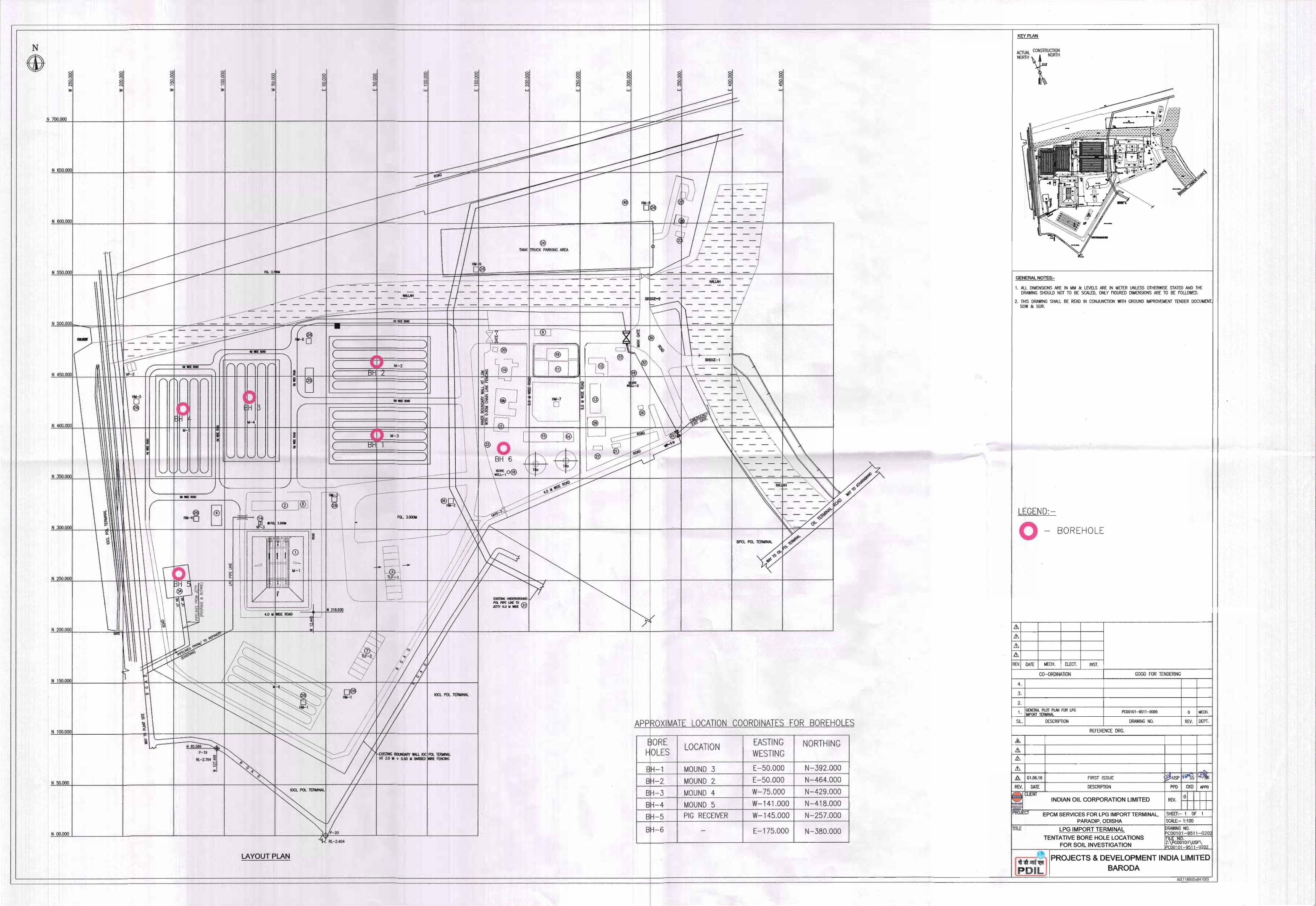
1.4 Key plan showing location of bore hole and other site investigation tests is
attached for reference – Drg no. PC00101-9511-0202 R0
2.0 SCOPE OF WORK
2.1 The scope of work consists of Geotechnical Investigation work carrying out at site
and at laboratory various soil tests to arrive at the following:-
a) Type of foundation system for:
Base for Sand filled Mound Retaining wall for Mound Barricading structure Control room & Pump House Pipe rack, pipe bridge, pipe trestle, pipe sleeper, pipe support RCC culvert Pump foundation Support for other related utilities
b) Depth below the ground level at which the foundation system is to be laid.
c) Allowable bearing pressure on the foundation levels / pile capacity for
Bored cast - in - situ / Driven cast - in - situ piles and their SBC and pile
diameter with pile capacity in compression, tension & lateral etc.
d) All soil dynamic parameters for design of foundation for vibratory
equipments.

SCOPE OF WORK FOR GEOTECHNICAL INVESTIGATION WORK
AT LPG IMPORT TERMINAL
PC00101-SOW-0202 0
DOCUMENT NO. REV
Sheet 4 of 4
All rights reserved
e) CBR for design of RCC road/pavement and suggestive soil improvement
technique, if required.
f) Sample calculation for all arrived soil parameters i.e. pile capacity, SBC,
etc.
g) Type of cement and the type of rebar to be used.
2.2 The scope of work under this includes supervision through qualified and technical
personnel, skilled and unskilled labor, etc. and mobilization of all relevant and
adequate plants, tools and tackles equipment, machineries, etc., to carry out all
works for successful completion of the job. All the works shall be carried out
strictly in accordance with the "Technical Specifications” enclosed with this
document.
2.3 The scope of work covered under soil investigation work includes setting out of
bore hole location as per drawing, field investigation, laboratory testing and
submission of soil investigation report incorporating the observations made during
the field investigation and result of laboratory tests, analysis of all results,
foundation recommendations with calculation and other related information along
with necessary charts, curves and drawings and submission of draft and final
report as per SOR.
2.4 The scope of work is defined in general and is not limited to above, Bidder has
also to carry out job which is not listed here but required for Completion of Works.
3.0 SITE CLEANING
During investigation and on completion of investigation clearing all the debris and
waste materials scattered around the site and disposal of the same as per direction
of the Engineer-in-Charge, shall be in the scope of the Contractor.


TECHNICAL SPECIFICATIONS FOR GEOTECHNICAL INVESTIGATION WORK
AT LPG IMPORT TERMINAL
PC00101-TS-0208 0
DOCUMENT NO. REV
Sheet 2 of 17
All rights reserved
CONTENTS
Sl. No. Description Sheet Number
1.00 SCOPE 3
2.00 CODES 3
3.00 SOIL INVESTIGATION 4
3.01 BORING 4
3.02 IN-SITU TESTING 6
3.03 SAMPLING 11
4.00 LABORATORY TESTING ON SOILS 12
5.00 REPORT 15
ANNEXURE LABORATORY TEST RESULTS 17

TECHNICAL SPECIFICATIONS FOR GEOTECHNICAL INVESTIGATION WORK
AT LPG IMPORT TERMINAL
PC00101-TS-0208 0
DOCUMENT NO. REV
Sheet 3 of 17
All rights reserved
1.00 SCOPE
1.01 These specifications cover the procedure for soil investigations for foundations.
1.02 The work shall be carried out in accordance with the specification set out below and as directed by the Engineer-in-Charge, where necessary.
2.00 CODES
2.01 These specifications conform to the Indian Standards on soils and Foundations as given below :
IS: 1498 Classification and Identification of Soil for General Engineering Purposes.
IS: 1888 Method of Load Tests on Soil.
IS: 1892 Code of practice for Site Investigations for Foundations.
IS: 2131 Method for Standard Penetration Test.
IS: 2132 Code of Practice for Thin Walled Tube sampling of soils.
IS: 2720 Method of Test for Soils ( Relevant Parts ).
IS: 2911 Code of practice for design and construction of pile foundations. (Part-I)
Section-1: Driven cast-in-situ concrete piles.
Section-2: Bored cast-in-situ piles.
Section-3: Driven precast concrete piles.
IS: 2911 Code of practice for design and construction of pile foundations. (Part-II) Under Reamed Piles.
IS: 4434 Code of Practice for In-Situ-Vane-Shear Test for Soils.
IS: 4968 Method for sub-surface sounding for Soil: (Part-I) Dynamic Method Using Cone without Bentonite Slurry.
IS: 4968 Method for sub-surface sounding for Soil: (Part-II) Dynamic Method Using Cone and Bentonite Slurry.
IS: 4968 Method for sub-surface sounding for Soil: (Part-III) Static Cone Penetration Test.
IS: 5249 Method of Tests for Determination of In-situ Dynamic Properties of Soils.

TECHNICAL SPECIFICATIONS FOR GEOTECHNICAL INVESTIGATION WORK
AT LPG IMPORT TERMINAL
PC00101-TS-0208 0
DOCUMENT NO. REV
Sheet 4 of 17
All rights reserved
IS: 5529 Code of Practice for in-situ permeability tests : (Part-I) Test in overburden.
IS: 6403 Code of Practice for determination of allowable bearing pressure on shallow foundations.
IS: 6935 Determination of water level in borehole.
IS: 8009 Code of practice for calculation of settlement of foundations : Shallow foundations subject to symmetrical static vertical loads.
IS: 9118 Method for measurement of pressure by means of manometer.
2.02 Reference to any code in these specifications shall mean the Latest revision of the code unless otherwise mentioned. In the event of any conflict between the requirements in these specifications and the referred codes, the former shall govern.
3.00 SOIL INVESTIGATIONS
3.01 BORING
Boring shall be carried out in accordance with the provisions of IS: 1892 and as per the specifications given below:
3.01.1.0 AUGER BORING
3.01.1.1 Augers shall be of helical or post hole type and may be manually or power operated. The Augers shall be used only up to ground water level and no water shall be added during auger boring. The diameter of the hole shall be minimum 100 mm and preferably 150 mm.
3.01.1.2 Uncased holes shall be permitted only up to a depth where the sides of the hole can stand unsupported. In case side fall is noticed, steps shall be taken immediately to stabilize the holes by using bentonite slurry or by casing pipes as directed by the Engineer.
3.01.1.3 No water shall be added while boring through cohesive soils and cohesion less soils above water table. While boring through cohesion less soil below water table, water in the casing shall always be maintained at or above the water table.
3.01.1.4 The cuttings brought up by the auger shall be carefully examined and soil descriptions duly recorded. Representative samples shall be preserved for laboratory testing.
3.01.1.5 Wherever in-situ tests are conducted and undisturbed samples are obtained at specified depths from the borehole, care shall be taken to ensure that the borehole is properly cleaned and free from foreign matters at the time of conducting these operations.
3.01.1.6 Water table in the borehole shall be carefully recorded and reported.

TECHNICAL SPECIFICATIONS FOR GEOTECHNICAL INVESTIGATION WORK
AT LPG IMPORT TERMINAL
PC00101-TS-0208 0
DOCUMENT NO. REV
Sheet 5 of 17
All rights reserved
3.01.2.0 SHELL AND AUGER BORING
3.01.2.1 Augers shall be of helical or post hole type and may be manually operated. The diameter of the hole shall be minimum 100 mm and preferably 150 mm.
3.01.2.2 Specifications set forth in clauses 3.01.1.2 to 3.01.1.7 for Auger Borings shall apply to shell and Auger borings also.
3.01.2.3 Auger shall be used for soft to firm clay and for silt deposits at upper depths of 10 meters or up to the water table whichever is deeper. For deeper depths in such deposits and for very stiff to hard clays and dense sands located at any depth, use of shell may be made.
3.01.2.4 While boring in soft clays and in sandy deposits below water table, it shall be ensured that the shell diameter shall be at least 25 to 50 mm less than the casing diameter. This is to ensure that suction is not created in the borehole during withdrawal of the shell with consequent "Caving in and blowing" in the boreholes.
3.01.3.0 ROTARY MUD CIRCULATION DRILLING
3.01.3.1 The drilling shall be carried out manually conforming to IS: 1892 or by use of a suitable mechanical rig.
3.01.3.2 Drilling up to water table shall be done by auger and provisions of clauses 3.01.1.1 to 3.01.1.7 shall apply. Below the water table drilling by rotary and circulation shall be adopted.
3.01.3.3 Use of percussion tools may be permitted in very stiff to hard clays and dense sandy deposits.
3.01.3.4 Use of chisel/ percussion shall be permitted exclusively in strata having SPT below count greater than 100/30 cm penetration or less. If the rate of advancement of boring by chiseling is little or slow (i.e. less than 20cm in 4 hrs). The contractor may adopt core drilling with Nx size Tc bit. Where the core recovery exceeds 25%, the Tc bits shall be used for coring in soft/weathered rock and diamond bits for hard rock having core recovery 50% or more. Double tube core barrel shall be used for coring. The drill core and cutting shall be preserved carefully in core boxes and core recovery & RQD of each of the core taken shall be recorded. The selected core samples shall be transported to the laboratory for testing at no additional cost. The cost of core boxes shall be deemed to have included in the quoted rates. The contractor shall at his own cost transport the core boxes to the place of storage as directed by the Engineer-In-Charge.
3.01.4.0 TERMINATION CRITERIA The boreholes shall be terminated as per the following criteria:
a) When the specified depth of borehole is reached and drilling in soft/weak/weathered rock reaches 5.0m depth
or b) Drilling in hard rock reaches 1m depth.

TECHNICAL SPECIFICATIONS FOR GEOTECHNICAL INVESTIGATION WORK
AT LPG IMPORT TERMINAL
PC00101-TS-0208 0
DOCUMENT NO. REV
Sheet 6 of 17
All rights reserved
If very hard soil is met within the borehole at depths shallower than specified in tender documents, the bore- hole shall be advanced by chiseling. If in the opinion of the Engineer-in-Charge, the rate of advancement of borehole is still low, coring may be resorted to subsequently.
3.01.5.0 BORE-LOG
Immediately on completion of a borehole, bore-log shall be prepared and submitted to the Engineer-in-Charge in triplicate. Detailed bore logs indicating co-ordinates, Reduced level, ground water table etc., sub soil section along various profiles indicating boreholes nos., depth wise in-situ tests like SPT
3.01.6.0 BACK-FILLING OF BOREHOLES
Backfilling of Bore holes to be done with 1:1Cement: Bentonite or Mud grout.
3.02 IN-SITU TESTING
3.02.1.0 STANDARD PENETRATION TEST
3.02.1.1 The test shall be conducted at regular intervals or at a depth where the strata changes, whichever occurs earlier. Up to a depth of 10 m, interval shall be 1.5 m. Thereafter SPT tests shall be conducted at an interval of 2 m up to 20 m depth, followed by an interval of 3 m beyond 20 m depth.
3.02.1.2 The test shall be carried out by driving a standard split spoon by means of 63.5 kg hammer with a 75 cm free fall. Detailed procedure of testing, as specified in IS: 2131 - "Method of Standard Penetration Test in Soils" shall be followed. The samples obtained in the split spoon shall be labeled and preserved for identification tests in the laboratory.
3.02.1.3 The standard penetration test shall be discontinued when N is greater than 75 blows for 30 cms of penetration.
3.02.2.0 VANE SHEAR TEST
3.02.2.1 These tests shall be conducted in soft to firm clays and sensitive clays. These tests shall also be conducted in case of stiff fissured clays where samples cannot be taken.
3.02.2.2 Test may be conducted from the bottom of bore-hole or by direct penetration from ground surface as per IS: 4434. The results of vane shear test shall be maintained and submitted to the Engineer-in-Charge in triplicate.
3.02.2.3 The apparatus used for Vane Shear Tests shall satisfy the requirements conforming to IS: 4434.
3.02.2.4 The following points shall be carefully supervised in the field :
a. The vane selected shall be the largest size suitable for the general soil conditions at site.
TECHNICAL SPECIFICATIONS FOR GEOTECHNICAL INVESTIGATION WORK
AT LPG IMPORT TERMINAL
PC00101-TS-0208 0
DOCUMENT NO. REV
Sheet 7 of 17
All rights reserved
b. The vane shall be frequently checked for straightness.
c. If torque versus rotation curve is to be determined, It is essential that the torque rods shall be calibrated prior to the use in the field. The amount of rod twist, if any, shall be established in degree per meter per unit torque. This correction becomes progressively more important as the depth of test increases. The calibration shall be made at least to the maximum depth of testing anticipated.
d. During the test, it is essential that the rods and Vane are placed centrally in the bore-hole. For this purpose guides shall be used at an interval in depth of not more than 5.0 m.
e. The apparatus shall be checked and calibrated as and when required.
f. Straightness of vane shall be checked while the entire assembly of vane connected with rod is lowered to the bottom of bore-holes. Vane shall be pushed with a moderate steady force up to a depth of five times the bore-hole diameter below the bottom of bore-holes. Precaution shall be taken to ensure that no torque is applied to the torque rods during the application of thrust. No hammering shall be done.
g. 5-minute’s time shall be allowed to lapse after insertion of vane.
h. Torque indicator readings shall be recorded at intervals of 30 seconds until the vane readings drop appreciably from the maximum.
i. Samples shall be collected from the levels at which the tests have been conducted.
j. In case of tests by Direct Penetration from Ground Surface, rods shall remain tight when vane is lowered. Guides shall be placed at every 3.0 m. to centralize and reduce friction between rods and extension pipe.
3.02.3.0 DYNAMIC CONE PENETRATION TEST
3.02.3.1 The method of conducting the tests and the details of the equipment shall conform to one of the two alternatives given below. The particular method to be followed is indicated under specific requirements:
a. The test shall be conducted in accordance with IS: 4968 (Part- I). The cone size shall be 50 mm.
b. The test shall be conducted in accordance with IS: 4968 (Part- II). A continuous flow of bentonite slurry shall be maintained through the rods and the cone so as to avoid friction between the rods and the soil. The cone size shall be 65 mm. and provided with vents for flow of bentonite slurry.
3.02.3.2 Dynamic cone penetration tests shall be terminated when blow counts (Ne) exceed 150 for two successive penetrations of 30 cms. each.

TECHNICAL SPECIFICATIONS FOR GEOTECHNICAL INVESTIGATION WORK
AT LPG IMPORT TERMINAL
PC00101-TS-0208 0
DOCUMENT NO. REV
Sheet 8 of 17
All rights reserved
3.02.3.3 The results shall be recorded in a suitable tabular form enclosed, giving blow counts for every 30 cm. penetration, supplemented by a graphical plot of blow counts versus depth.
3.02.4.0 STATIC CONE PENETRATION TEST
3.02.4.1 The method of conducting tests and the details of the equipment used for this test shall conform to the requirements of IS: 4968 (Part- III).
3.02.4.2 The capacity of the equipment to be used for test shall not be less than 3.0 tonnes but preferably 10.0 tonnes.
3.02.4.3 The test shall not be carried out on gravelly soils and for soils with Standard Penetration Value "N" greater than 50.
3.02.5.0 PLATE LOAD TEST
3.02.5.1 Plate Size and Thickness:
a. For Clayey and silty soils and for loose to medium compact sandy soils (N<15), chequered plate of 60 x 60 cm shall be used. Alternatively, circular plate of equivalent area also may be used.
b. For dense sandy or gravely soils (15<N<30) the smallest size shall be 30 cm. square and largest 75 cm. square. Circular plates of equivalent areas may also be used.
c. The minimum thickness of the chequered plate shall be 25 mm.
3.02.5.2 Test Pit:
a. Test pit shall be at least five times as wide as the test plate and the depth of the pit shall be the same as the depth of actual foundations.
b. If the test is to be done on strata below water table, the water level shall be maintained at the plate level, throughout the test by dewatering, especially in sandy soils.
c. The test shall be conducted immediately after excavation of soil.
3.02.5.3 Placing of Test Plate:
Plate shall be placed on the soil by spreading fine sand in a layer not exceeding 5 mm carefully leveled and set horizontally at the bottom of the pit. A minimum seating pressure of 70 g/cm² shall be applied and removed before starting of the load test.
3.02.5.4 The method of conducting Plate Load Tests shall conform to IS: 1888.
3.02.5.5 Settlement and Observation:

TECHNICAL SPECIFICATIONS FOR GEOTECHNICAL INVESTIGATION WORK
AT LPG IMPORT TERMINAL
PC00101-TS-0208 0
DOCUMENT NO. REV
Sheet 9 of 17
All rights reserved
a. Settlement shall be recorded with at least two dial gauges, resting at diametrically opposite ends of the plate.
b. Settlement shall be observed for each increment of load after an interval of 1, 2.25,4, 6.25,9, 16, 25, 36 and 64 minutes and thereafter every one hour.
c. The next load increment shall be applied when the rate of settlement is less than 0.02 mm/hr with a minimum period of two hours. For computing the rate of settlement its extrapolation for periods less than one hour shall not be permitted.
3.02.5.6 Record:
a. Record shall consist of the following:
1. Load-settlement reading in tabular form.
2. Time-settlement curve for each load stage.
3. Load-settlement curve in natural and log-log scale.
4. Modulus of sub-grade reaction evaluated from test.
b. In addition to above, the record shall also contain the followings :
1. Date
2. List of personnel
3. Weather conditions
4. Irregularity in routine procedure, if any.
3.02.5.7 Post Test Requirements:
a. Back-filling of the pit shall be carried out in an approved manner and as per the directions of Engineer-in-Charge on completion of test.
b. An auger bore-hole shall be made from the depth of test extending to a depth of 6.0 m below test depth so as to ascertain the nature of sub-soil test depth. If required, undisturbed samples shall be obtained at suitable depths from bore-hole.
3.02.6.0 FIELD CBR TEST
This test shall be conducted as per IS: 2720 (Part-XXXI) at specified depth after removing top soil, vegetation and organic matter.

TECHNICAL SPECIFICATIONS FOR GEOTECHNICAL INVESTIGATION WORK
AT LPG IMPORT TERMINAL
PC00101-TS-0208 0
DOCUMENT NO. REV
Sheet 10 of 17
All rights reserved
3.02.7.0 DYNAMIC SOIL TESTS
3.02.7.1 General
The following tests shall be conducted for the determination of dynamic properties of soil for use in the design of foundations subject to vibratory loads:
3.02.7.2 Wave Velocity Measurements
The test set up and method of conducting the tests shall conform to IS: 5249. The concrete block shall be cast at the expected foundation level. After completion of the test, back filling of the pit shall be carried out in an approved manner and as per the directions of the Engineer-in-Charge after removing the concrete block.
3.02.7.3 Resonance Tests
The equipment set up and method of conducting the tests shall conform to IS: 5249.
3.02.7.4 Cyclic Plate Load Test
The test set up and plate size shall conform to that for plate load tests. After stabilization of settlements for each load increment, load shall be removed and elastic rebound and residual settlement recorded.
3.02.7.5 Repeated Triaxial Shear Test
This test shall be carried out for confining pressure ranging from 0.5 Kg/cm² 4.0 Kg/cm².
The triaxial sample shall first be subjected to an initial load equal to the anticipated static working load, which shall be indicated at the time of testing. Positive and negative values of a small increment of load shall then be applied to the sample in cycles and graph plotted of stress against strain. E-Value shall be obtained from this plot after obtaining a stable state.
Results of all the above tests shall be incorporated in the form of a plot of shear modulus Vs. confining pressure for a range of pressure up to 4.0 Kg/cm². All the stress-strain diagrams as well as Mohr’s circle envelopes is to be included in the report.
3.02.7.6 Electrical Resistivity Test This test shall be conducted as per Appendix B, Clause 3.2 of IS1892 - 1979. The test shall be done by using 4 points. The locations where ERT IS to be performed shall be finalized in consultation with EIC.

TECHNICAL SPECIFICATIONS FOR GEOTECHNICAL INVESTIGATION WORK
AT LPG IMPORT TERMINAL
PC00101-TS-0208 0
DOCUMENT NO. REV
Sheet 11 of 17
All rights reserved
3.03 SAMPLING
3.03.1.0 Sampling Record:
All samples (disturbed and undisturbed) collected from the pit/bore-hole shall be labeled and attached to the top of sampler, in case of undisturbed samples. In case of samples collected in Jar or other containers, the label should be properly pasted to the Jar/container.
3.03.2.0 Undisturbed Soil Samples from Borehole:
3.03.2.1 Samplers for recovering undisturbed samples from cohesive soils at the specified depth shall conform to IS: 2132. However, use of samples less than 70 mm diameter shall not be permitted.
3.03.2.2 The sampling procedure shall conform to IS: 2132. Both the area ratio of the cutting edge, as well as recovery ratio of the sample shall be measured and reported. For normal soils, area ratio of the sampling tubes, shall conform to IS: 2132, that is it may vary from 10.9 percent to 12.4 percent but for sampling in very hard and dense soils, use of thick walled sampling tubes with area ratio not exceeding 20% may be permitted subject to the approval of the Engineer-in-Charge.
3.03.2.3 In order to reduce the wall friction, suitable precautions such as oiling inside and outside the sampling tubes shall be observed. The sampling tube shall have smooth finish.
3.03.2.4 In soft to firm clays, undisturbed samples shall be collected by pushing the tube continuously without impact or twisting. Driving of sampling tubes shall be permitted only if stiff to very stiff and hard deposits exists.
3.03.2.5 For highly sensitive soils, piston samples shall be employed.
3.03.2.6 For soft clays exceeding more than 15 m depth from the ground level, collection of undisturbed samples shall be supplemented by the In-situ Vane shear test.
3.03.2.7 The top and bottom of the sample shall be clearly marked on the sampling tube.
3.03.2.8 Undisturbed samples shall be tested within a period of two weeks of taking them from the bore holes of Trial pit.
3.03.2.9 If any space is left between the end of the tube and top of wax, the same shall be tightly packed with raw dust or any other suitable material. A close fitting bid or screwed cap shall then be placed on each end of the tube and held in position by adhesive tape.
3.03.3.0 Undisturbed Soil Samples from Trial Pits
3.03.3.1 Samples shall be obtained at specified depths from Trial Pits in a timber or steel box as under:

TECHNICAL SPECIFICATIONS FOR GEOTECHNICAL INVESTIGATION WORK
AT LPG IMPORT TERMINAL
PC00101-TS-0208 0
DOCUMENT NO. REV
Sheet 12 of 17
All rights reserved
A benching shall be made at the level where it is proposed to take the sample. A cube of 30 cm size shall be formed by careful trimming with knife or any other suitable sharp instrument. A timber box having dimensions slightly larger than the soil cube shall be slipped on it so as to act as a container and the sample removed from the pit without causing any disturbance.
3.03.3.2 After recovery of the sample, all exposed faces shall be sealed with wax to prevent moisture loss and the sample shall be properly labeled and transferred to the laboratory immediately.
3.03.4.0 Disturbed Soil Samples
Disturbed soil samples shall be collected at every half a meter and at every change of strata from boreholes as well as from trial pits. Identification labels indicating depth. Borehole number and visual soil classification shall be affixed on the containers.
3.03.5.0 Water Samples
3.03.5.1 Samples of ground water shall be obtained from the specified boreholes at the depths specified by Engineer-in-Charge.
3.03.5.2 At the specified depth water shall be bailed or pumped out so that fresh ground water flows into the borehole. Care shall be taken in avoiding any contamination with surface water at any time. Water sample shall be collected in a five liter polythene or glass container and labeled properly.
4.00 LABORATORY TESTING OF SOILS
4.01 STORING OF SOIL SAMPLES IN LABORATORY
4.01.1.0 Soil samples shall be inspected and tested shortly after their arrival at the laboratory. Proper arrangement for storing shall be made in cases where testing of samples is not possible immediately after they are brought to the laboratory.
4.01.2.0 Bags of canvas, cans and bins can be used for storing large quantities of soil. The containers should have a label or tag which gives such data as soil type, project location, sampling date, boring number, sample depth, etc.
4.01.3.0 If the undisturbed clay samples are taken from pit, they should be covered with a protective coating. The coating shall preferably be with wax having melting point between 120° to 160°F. The wax coating can be applied by either dipping the soil sample in the melted wax or using a soft brush to spread the melted wax. Wax should not be heated to more than a few degrees above its melting temperature, since heating to higher temperatures tend to drive off more volatile hydro-carbons, thus making the wax more permeable and more brittle upon coating.
4.01.4.0 If the soil sample is to be stored for more than 15 days, a protective coating of wax, in more than one layer, is recommended with a total thickness of 12 mm to 18 mm.

TECHNICAL SPECIFICATIONS FOR GEOTECHNICAL INVESTIGATION WORK
AT LPG IMPORT TERMINAL
PC00101-TS-0208 0
DOCUMENT NO. REV
Sheet 13 of 17
All rights reserved
4.01.5.0 A few selected soil samples shall be stored in the laboratory till the soil investigation report is finalized and approved by the Engineer.
4.02 HANDLING OF UNDISTURBED SAMPLES IN LABORATORY
4.02.1.0 The undisturbed samples shall be handled in the laboratory with due precaution to avoid disturbances and loss of moisture content which may adversely affect the test results.
4.02.2.0 Unprotected samples shall never be handled with bare hands because the hands foster disturbance and loss of moisture. The sample shall be protected by using Aluminium cellophane or wax paper before handling it.
4.02.3.0 When transporting a specimen, it should be supported over its entire length by using a mould, plate or paper sling.
4.02.4.0 A chunk from an undisturbed sample collected from pit shall be cut with a wire saw which consists of a frame with a piano wire stung tightly across it. Any wax or other covering used to protect the sample shall be cut with a knife or hacksaw. Care shall be taken when trimming the finished specimen. The wire in the wire saw used for final trimming shall be smaller in diameter than that used for preliminary cutting and the wire shall be cleaned prior to each cut.
4.02.5.0 In case of samples taken in sample tubes, the samples shall be extrude from their tubes by a steady pushing process and not by a jerky or driving one. Prior to extrusion, the plug which protects the end of the soil shall be removed by scrapping it with a knife or sawing off that portion of the tube which contains plug. The extrusion shall employ the same direction of motion or motion of the soil with respect to the tube as existed during sampling, because a reversal of stress tends to cause disturbance.
4.03 PROCEDURES OF TESTING
4.03.1.0 All apparatus used for laboratory testing shall conform to the specifications laid down in the relevant Indian Standards.
4.03.2.0 All testing procedures shall conform to those laid down in relevant Indian Standards.
4.03.3.0 For proper interpretation, results of each laboratory test shall be presented either as given in relevant Indian Standard or as specified in specific requirements.
4.03.4.0 Attenberg Limits The tests result should include liquid limit and plastic limit of the soil samples tested. These tests should be conducted as per IS: 2720 Part V.
4.03.5.0 Natural Moisture Content
In case of organic soils, the oven temperature shall be 60 deg. C and not 105 deg.C.

TECHNICAL SPECIFICATIONS FOR GEOTECHNICAL INVESTIGATION WORK
AT LPG IMPORT TERMINAL
PC00101-TS-0208 0
DOCUMENT NO. REV
Sheet 14 of 17
All rights reserved
4.03.6.0 Specific Gravity
This test should be conducted as per IS: 2720, Part 3.
4.03.7.0 Grain Size Distribution
Wherever applicable both the sieve and hydrometer analysis shall be conducted to indicate complete range of grain size in the soil sample tested. Generally, Hydrometer analysis will be carried out, wherever percentage passing No.200 sieve is greater than 30%.
4.03.8.0 Unconfined Compression Test
This test shall be conducted as per IS: 2720, Part X.
4.03.9.0 Free Swelling Index
This test shall be conducted as per IS: 2720, Part 40.
4.03.10.0 Swelling Pressure Test
This test shall be conducted as per IS: 2720, Part 41.
4.03.11.0 Consolidation Tests
The following loading stage shall be employed: 0, 0.1, 0.25, 1.0, 2.0, 4.0 and 8.0 kg / sq.cm. From e Vs log p curves, pre consolidation pressure shall be determined to establish whether the soil is normally consolidated or over consolidated. The point (e, p) showing initial condition of the soil under test must be specifically marked on the consolidation curves. Settlement predictions based on the field virgin compression curve shall only be acceptable. The procedure adopted in respect of obtaining compression indices from the field curve and that for computing settlements for the type of clay under consideration shall be clearly illustrated in the report. It is to be noted that deviations from the standard procedure of performing consolidation tests given in IS:2720 are permissible in order to enable computation of settlements based on the above procedure i.e. cycles (s) of loading, unloading and reloading shall be employed wherever required. The following curves shall be included in the report: a) e vs. : log p b) e vs. : p c) Compression vs.: log t or compression vs t. The choice of relationship depends upon the shape of the plot, which enables a clear determination of Cv, the coefficient of consolidation. The time period required for 50% and 90% primary consolidation should be given in the report. Computation of secondary settlements, if significant, shall also be made and included in the report.

TECHNICAL SPECIFICATIONS FOR GEOTECHNICAL INVESTIGATION WORK
AT LPG IMPORT TERMINAL
PC00101-TS-0208 0
DOCUMENT NO. REV
Sheet 15 of 17
All rights reserved
4.03.12.0 Chemical Tests on Water & Soil
Chemical tests shall be conducted on soil and water samples to report the following: a) pH b) Chloride c) Sulphate d) Sulphite e) Organic contents f) Total hardness
4.03.13.0 Proctor Density Tests
These tests shall be conducted as per IS: 2720 Part VII samples collected randomly in consultation with Engineer-in-Charge.
5.0 R E P O R T
5.01 The report shall state in brief the description of the test procedures employed. It shall contain all field and laboratory test results.
5.02 The report shall also include wherever required a sample calculation with reference to formula used to evaluate the various parameters.
5.03 Report shall also contain the summary of various soil parameters evaluated, in a Performa as given in ANNEXURE- A enclosed.
5.04 Report shall contain character and genesis of soil.
5.05 Detailed bore-logs, subsoil sections, laboratory and field test results both in tabular as well as in graphical form and a plot plan showing locations and reduced levels of bore holes and other tests.
5.06 Results obtained and their interpretation.
5.07 Recommendation for type, depth, ultimate and safe bearing pressure and settlement of foundations for the following structures:
i. Process units, power plants etc., which carry a heavy unit load.
ii. Non plant structures such as, substation, control room etc., which are lightly loaded.
iii. Other structures like base and retaining wall for mound, pipe rack, Pipe Bridge, pump foundations founded at or near ground surface.
5.08 Recommendations shall also be given for allowable bearing pressure and settlements for foundations of sizes ranging from 1 to 10 metres placed at different depths ranging from surface to 3 metres below the ground surface.

TECHNICAL SPECIFICATIONS FOR GEOTECHNICAL INVESTIGATION WORK
AT LPG IMPORT TERMINAL
PC00101-TS-0208 0
DOCUMENT NO. REV
Sheet 16 of 17
All rights reserved
5.09 Aggressiveness of soil and soil water to reinforced concrete and steel and other building materials.
5.10 Suitability of soil and degree of compaction of fill for the pavement and tank farms and recommendation for thickness of pavement for class AA and Class A loadings.
5.11 Modulus of subgrade reaction for pressure ranging up to 3 Kg/cm². The recommended values shall include the effect of size, shape and depth of foundation.
5.12 In case of poor soil conditions recommendations are to be made for the following:
a. Ground improvement techniques, stabilizing slopes, etc. adopting internationally accepted norms and practices considering economy of foundation system. In case of ground improvement, type(s) of improvement method(s) recommended, depth of treatment and settlements and bearing capacity estimates after treatment shall be indicated.
b. Pile foundations, if considered necessary. If so, type(s) of pile recommended (bored/driven), depth of pile, depth of fixity, negative skin friction, and safe load capacity for different sizes of piles. Sample calculations showing load carrying capacity of both driven & bored pile to be included in the soil report.
All recommendations shall be supported by back up calculations.
5.13 Any other information of special significance encountered during investigation and likely to have a bearing on design and construction.
5.14 Interim reports based on the data available shall be supplied to the Engineer-in-Charge at various stages of investigation for review/comments. Comments, if any, on these reports shall be duly incorporated in the final report.6 copies of final report along with soft copy to be submitted.
5.15 A set of longitudinal and transverse soil profile connecting various boreholes shall be presented in order to show the variation of soil stratum.

TECHNICAL SPECIFICATIONS FOR GEOTECHNICAL INVESTIGATION WORK
AT LPG IMPORT TERMINAL
PC00101-TS-0208 0
DOCUMENT NO. REV
Sheet 17 of 17
All rights reserved
Con
solid
atio
n Te
st m
v
(Kg/
Cm
2 )
Pr.
Ran
ge
(Kg/
Cm
2 )
She
ar T
est Ø
(Deg
.)
C
(Kg/
Cm
2 )
Atte
rber
g Li
mit P
L
(%)
LL
(%)
Gra
in S
ize
Dis
tribu
tion
Cla
y
(%)
Silt
(%)
San
d
(%)
Gra
vel
(%)
Sp.
G
ravi
Ty
Dry
D
ensi
ty
g/cc
)
Bul
k D
ensi
ty
(g/c
c)
NM
C
(%)
Brie
f D
escr
iptio
n
Dep
th
in
Met
re
Bor
ehol
e /
Pit
No.