Nortec RS Steam Humidifier Operation Manual · 7.3 Saving Fault and Service Histories to a USB...
80
Humidification and Evaporative Cooling 2582418-A EN | 06 AUG 2015 OPERATION MANUAL Steam humidifier Nortec RS
Transcript of Nortec RS Steam Humidifier Operation Manual · 7.3 Saving Fault and Service Histories to a USB...
Humidification and Evaporative Cooling
2582
418-
A E
N |
06 A
UG
201
5
OPERATION MANUALSteam humidifier Nortec RS
Thank you for choosing Nortec
Installation date (MM/DD/YYYY):
Commissioning date (MM/DD/YYYY):
Site:
Model:
Serial number:
ManufacturerNortec Humidity Ltd.2740 Fenton Road, Ottawa, Ontario K1T3T7TEL: 1.866.NORTEC1, FAX: 613.822.7964EMAIL: [email protected], WEBSITE: www.humidity.com
Proprietary NoticeThis document and the information disclosed herein are proprietary data of Nortec Humidity Ltd. Neither this do-cument, nor the information contained herein shall be reproduced, used, or disclosed to others without the written authorization of Nortec Humidity Ltd., except to the extent required for installation or maintenance of recipient's equipment.
Liability NoticeNortec Humidity Ltd. does not accept any liability due to incorrect installation or operation of the equipment or due to the use of parts/components/equipment that are not authorized by Nortec Humidity Ltd.
Copyright NoticeCopyright 2015, Nortec Humidity Ltd. All rights reserved.
Technical modifications reserved
3Contents
Contents
1 Introduction 51.1 Before You Begin 51.2 Notes on the Operation Manual 5
2 For Your Safety 7
3 Product Overview 93.1 Construction Nortec RS steam humidifier 93.2 Functional Description 103.3 System Overview Nortec RS 113.4 System Overview Nortec RS for Direct Room Humidification 12
4 Operation 134.1 First-time Commissioning 134.2 Display and Operating Elements 134.3 Commissioning After an Interruption of Operation 144.4 Notes on Operation 154.4.1 Inspections During Operation 154.4.2 Manual Draining of the Steam Cylinder 154.5 Taking the Unit Out of Operation 16
5 Operating the Control Software 175.1 Standard Operating Display 175.1.1 Operating Status Indication 185.1.2 Maintenance and Malfunction Indications 185.2 Navigating/Operating the Control Software 195.3 Information Functions 205.3.1 Accessing Support Information 205.3.2 Accessing System Information 205.4 Configuration 245.4.1 Accessing the "Configuration" Submenu 245.4.2 Activating/Deactivating and Configuration of Options – "Features" Submenu 245.4.3 Humidity Control Settings – "Control Settings" Submenu 315.4.4 Basic Settings – "General" Submenu 385.4.5 Communication Settings – "Communication" Submenu 395.5 Maintenance Functions 435.5.1 Accessing the "Service" Submenu 435.5.2 Performing Maintenance Functions – "Service" Submenu 435.5.2.1 Input Diagnostic Functions – "Input Diagnostics" Submenu 455.5.2.2 Relay Diagnostic Functions – "Relay Diagnostics" Submenu 465.6 Administration Settings 475.6.1 Accessing "Administrator" Submenu 475.6.2 Switching On/Off Password Protection and Software Updates Function -
Submenu "Administrator" 47
4 Contents
6 Maintenance 496.1 Important Notes on Maintenance 496.2 Maintenance Intervals 506.3 Maintenance List 516.4 Removing and Installing Components for Maintenance 526.4.1 Preparing the Nortec RS for Removal of Components 526.4.2 Removal and Installation of the Scale Collector Tank 536.4.3 Removal and Installation of the Steam Cylinder 556.4.4 Removal and Installation of the Drain Cup 586.4.5 Removal and Installation of the Filling Cup, the Level Unit and Water Hoses 596.4.6 Removal and Installation of the Drain Pump 606.4.7 Removal and Installation of the Inlet Valve 616.4.8 Removal and Installation of the Steam Cylinder Receptacle 626.5 Notes on Cleaning the Unit Components 636.6 Notes on Cleaning Agents 656.7 Resetting the Maintenance Counter 666.8 Performing Software Updates 67
7 Fault Elimination 687.1 Fault Indication 687.2 Malfunction List 697.3 Saving Fault and Service Histories to a USB Memory Stick 737.4 Notes on Fault Elimination 737.5 Replacing the Fuses and Backup Battery in the Control Unit 747.6 Resetting the Fault Indication 75
8 Taking Out of Service/Disposal 768.1 Taking Out of Service 768.2 Disposal/Recycling 76
9 ProductSpecification 779.1 Performance Data 779.2 Operating Data 789.3 Connections/Dimensions/Weights 78
5Introduction
1 Introduction
1.1 Before You Begin
Thank you for purchasing the NortecRSsteamhumidifier.
The Nortec RS steam humidifier incorporates the latest technical ad van ces and meets all recognized safety standards. Never-the-less, improper use of the Nortec RS steam humidifier may result in danger to the user or third parties, and/or damage to property.
To ensure a safe, proper, and economical operation of the Nortec RS steam humidifier, please observe and comply with all information and safety instructions contained in the present documentation as well as in the separate documentations of the components installed in the humidification system.
If you have questions, which are not or insufficiently answered in this documentation, please contact your Nortec representative. They will be glad to assist you.
1.2 Notes on the Operation Manual
LimitationThesubjectofthisoperationmanualistheNortecRSsteamhumidifierinitsdifferentversions. The various options and accessories are only described in-so-far as this is necessary for proper opera-tion of the equipment. Further information on options and accessories can be obtained in the respective instructions.
This operation manual is restricted to the commissioning, operation, maintenance and troubleshoot-ing of the Nortec RS steam humidifier and is meant for well trainedpersonnelbeingsufficientlyqualifiedfortheirrespectivework.
This operation manual is supplemented by various separate items of documentation (installation manual, spare parts list, etc.), which are included in the delivery as well. Where necessary, appropriate cross-references are made to these publications in the operation manual.
6 Introduction
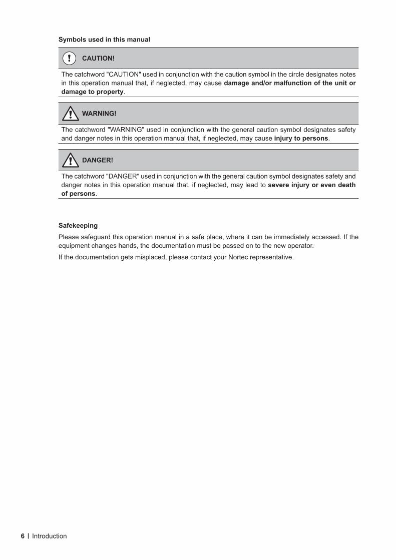
Symbols used in this manual
CAUTION!
The catchword "CAUTION" used in conjunction with the caution symbol in the circle designates notes in this operation manual that, if neglected, may cause damage and/or malfunction of the unit or damage to property.
WARNING!
The catchword "WARNING" used in conjunction with the general caution symbol designates safety and danger notes in this operation manual that, if neglected, may cause injury to persons.
DANGER!
The catchword "DANGER" used in conjunction with the general caution symbol designates safety and danger notes in this operation manual that, if neglected, may lead to severe injury or even death of persons.
SafekeepingPlease safeguard this operation manual in a safe place, where it can be immediately accessed. If the equipment changes hands, the documentation must be passed on to the new operator.
If the documentation gets misplaced, please contact your Nortec representative.
7For Your Safety
2 For Your Safety
GeneralEvery person working with the Nortec RS must have read and understood the Nortec RS operation manual before carrying out any work.Knowing and understanding the contents of the operation manual is a basic requirement for protecting personnel against any kind of danger, to prevent faulty operation, and to operate the Nortec RS safely and correctly.
All icons, signs and markings applied to the components of the Nortec RS must be observed and kept in readable state.
QualificationofpersonnelAll work described in this operation manual may only be carried out by specialists who are well trainedandadequatelyqualifiedandareauthorizedbythecustomer.For safety and warranty reasons any action beyond the scope of this manual must be carried out only by qualified personnel authorized by Nortec.
It is assumed that all persons working with the Nortec RS are familiar and comply with the appropriate regulations on work safety and the prevention of accidents.
The Nortec RS steam humidifier may not be used by persons (including children) with reduced physical, sensory or mental abilities or persons with lacking experience and/or knowledge, unless they are super-vised by a person responsible for their safety or they received instructions on how to operate the system. Children must be supervised to make sure that they do not play with the Nortec RS steam humidifier.
Intended useThe Nortec RS steam humidifier is intended exclusively for airhumidificationviaasteamdistributororablowerpackapprovedbyNortecwithinthespecifiedoperatingconditions. Any other type of application, without the written consent of Nortec, is considered as not conforming with the intended purpose and may lead to the Nortec RS becoming dangerous and will void any warranty.Operation of the equipment in the intended manner requires that all the information contained in this operation manual are observed (in particular the safety instructions).
8 For Your Safety
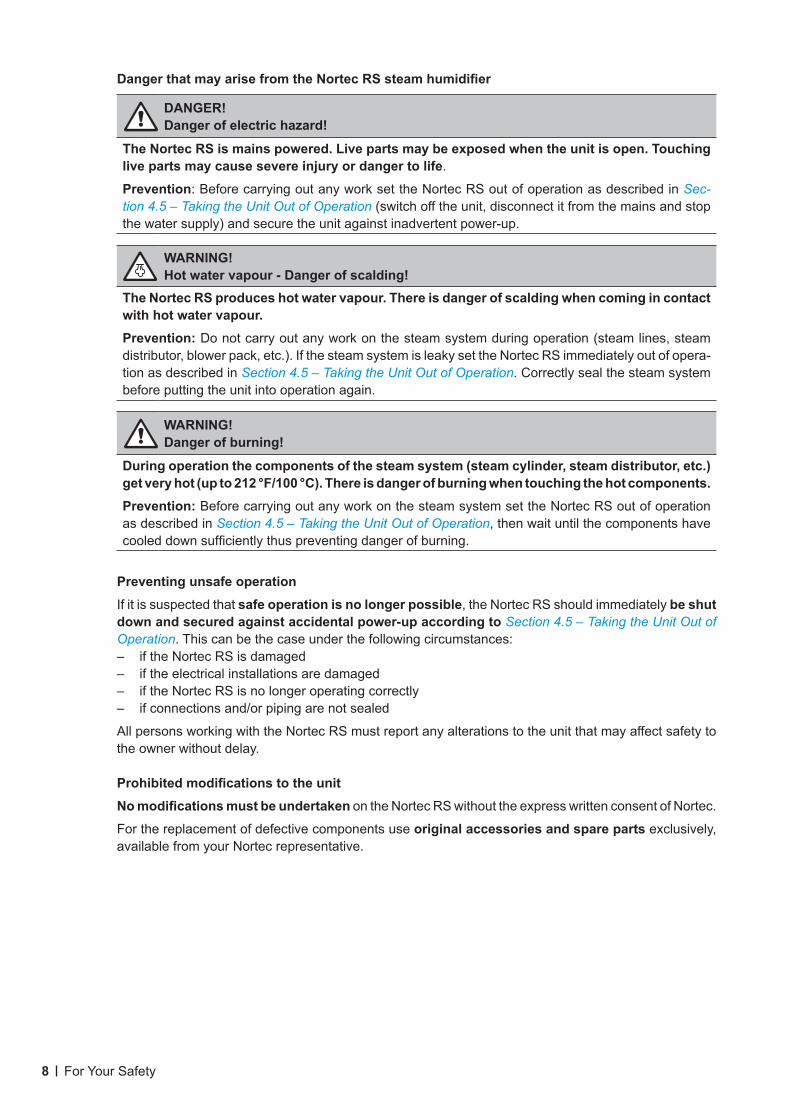
DangerthatmayarisefromtheNortecRSsteamhumidifier
DANGER!Dangerofelectrichazard!
The Nortec RS is mains powered. Live parts may be exposed when the unit is open. Touching live parts may cause severe injury or danger to life.
Prevention: Before carrying out any work set the Nortec RS out of operation as described in Sec-tion 4.5 – Taking the Unit Out of Operation (switch off the unit, disconnect it from the mains and stop the water supply) and secure the unit against inadvertent power-up.
WARNING! Hot water vapour - Danger of scalding!
The Nortec RS produces hot water vapour. There is danger of scalding when coming in contact with hot water vapour. Prevention: Do not carry out any work on the steam system during operation (steam lines, steam distributor, blower pack, etc.). If the steam system is leaky set the Nortec RS immediately out of opera-tion as described in Section 4.5 – Taking the Unit Out of Operation. Correctly seal the steam system before putting the unit into operation again.
WARNING!Danger of burning!
During operation the components of the steam system (steam cylinder, steam distributor, etc.) get very hot (up to 212 °F/100 °C). There is danger of burning when touching the hot components.Prevention: Before carrying out any work on the steam system set the Nortec RS out of operation as described in Section 4.5 – Taking the Unit Out of Operation, then wait until the components have cooled down sufficiently thus preventing danger of burning.
Preventing unsafe operationIf it is suspected that safe operation is no longer possible, the Nortec RS should immediately be shut down and secured against accidental power-up according to Section 4.5 – Taking the Unit Out of Operation. This can be the case under the following circumstances:– if the Nortec RS is damaged– if the electrical installations are damaged– if the Nortec RS is no longer operating correctly– if connections and/or piping are not sealed
All persons working with the Nortec RS must report any alterations to the unit that may affect safety to the owner without delay.
ProhibitedmodificationstotheunitNomodificationsmustbeundertaken on the Nortec RS without the express written consent of Nortec.
For the replacement of defective components use original accessories and spare parts exclusively, available from your Nortec representative.
9Product Overview
3 Product Overview
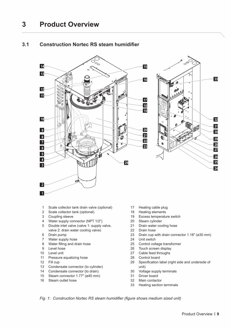
3.1 ConstructionNortecRSsteamhumidifier
1 Scale collector tank drain valve (optional) 2 Scale collector tank (optional) 3 Coupling sleeve 4 Water supply connector (NPT 1/2") 5 Double inlet valve (valve 1: supply valve,
valve 2: drain water cooling valve) 6 Drain pump 7 Water supply hose 8 Water filling and drain hose 9 Level hose 10 Level unit 11 Pressure equalizing hose 12 Fill cup 13 Condensate connector (to cylinder) 14 Condensate connector (to drain) 15 Steam connector 1.77" (ø45 mm) 16 Steam outlet hose
17 Heating cable plug 18 Heating elements 19 Excess temperature switch 20 Steam cylinder 21 Drain water cooling hose 22 Drain hose 23 Drain cup with drain connector 1.18" (ø30 mm) 24 Unit switch 25 Control voltage transformer 26 Touch screen display 27 Cable feed throughs 28 Control board 29 Specification label (right side and underside of
unit) 30 Voltage supply terminals 31 Driver board 32 Main contactor 33 Heating section terminals
Fig. 1: Construction Nortec RS steam humidifier (figure shows medium sized unit)
29
14
13
12
11
10
9
8
3
4
5
7
6
1
2
21
20
23
22
16
15
18
19
17
27
32
33
24
26
25
31
28
30
29
10 Product Overview
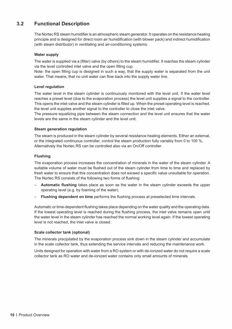
3.2 Functional Description
The Nortec RS steam humidifier is an atmospheric steam generator. It operates on the resistance heating principle and is designed for direct room air humidification (with blower pack) and indirect humidification (with steam distributor) in venti lating and air-conditioning systems.
Water supplyThe water is supplied via a (filter) valve (by others) to the steam humidifier. It reaches the steam cylinder via the level controlled inlet valve and the open filling cup.Note: the open filling cup is designed in such a way, that the supply water is separated from the unit water. That means, that no unit water can flow back into the supply water line.
Level regulationThe water level in the steam cylinder is continuously monitored with the level unit. If the water level reaches a preset level (due to the evaporation process) the level unit supplies a signal to the controller. This opens the inlet valve and the steam cylinder is filled up. When the preset operating level is reached, the level unit supplies another signal to the controller to close the inlet valve.The pressure equalizing pipe between the steam connection and the level unit ensures that the water levels are the same in the steam cylinder and the level unit.
Steam generation regulationThe steam is produced in the steam cylinder by several resistance heating elements. Either an external, or the integrated continuous controller, control the steam production fully variably from 0 to 100 %.Alternatively the Nortec RS can be controlled also via an On/Off controller.
FlushingThe evaporation process increases the concentration of minerals in the water of the steam cylinder. A suitable volume of water must be flushed out of the steam cylinder from time to time and replaced by fresh water to ensure that this concentration does not exceed a specific value unsuitable for operation.The Nortec RS consists of the following two forms of flushing:
– Automaticflushing takes place as soon as the water in the steam cylinder exceeds the upper operating level (e.g. by foaming of the water).
– Flushing dependent on time performs the flushing process at preselected time intervals.
Automatic or time-dependent flushing takes place depending on the water quality and the operating data. If the lowest operating level is reached during the flushing process, the inlet valve remains open until the water level in the steam cylinder has reached the normal working level again. If the lowest operating level is not reached, the inlet valve is closed.
Scale collector tank (optional)The minerals precipitated by the evaporation process sink down in the steam cylinder and accumulate in the scale collector tank, thus extending the service intervals and reducing the maintenance work.
Units designed for operation with water from a RO system or with de-ionized water do not require a scale collector tank as RO water and de-ionized water contains only small amounts of minerals.
11Product Overview
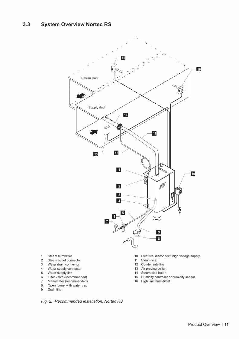
3.3 System Overview Nortec RS
1 Steam humidifier2 Steam outlet connector3 Water drain connector4 Water supply connector5 Water supply line6 Filter valve (recommended)7 Manometer (recommended)8 Open funnel with water trap9 Drain line
10 Electrical disconnect, high voltage supply 11 Steam line12 Condensate line13 Air proving switch14 Steam distributor15 Humidity controller or humidity sensor16 High limit humidistat
Fig. 2: Recommended installation, Nortec RS
9
8
10
1
2
3
4
5
7
6
13
15
16
11
14
12
Return Duct
Supply duct
12 Product Overview
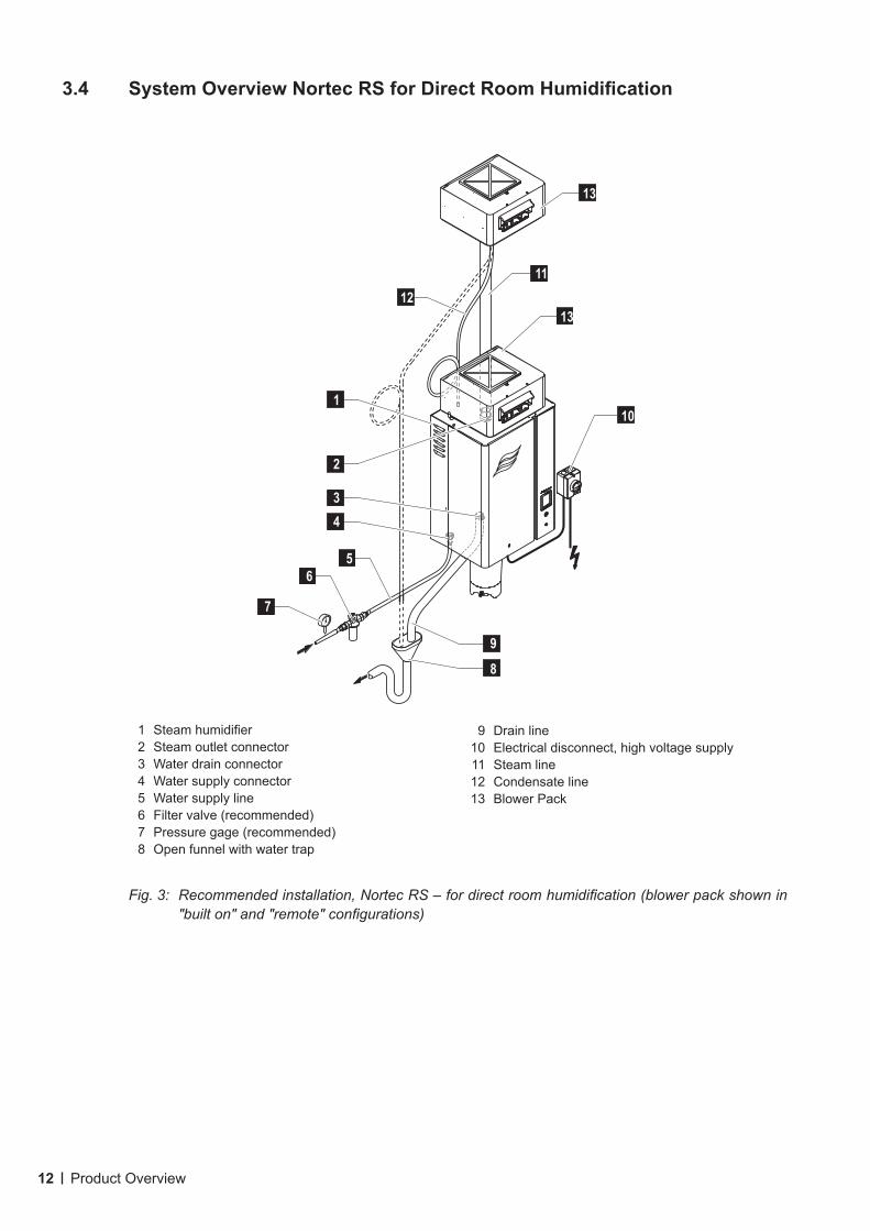
3.4 SystemOverviewNortecRSforDirectRoomHumidification
1 Steam humidifier2 Steam outlet connector3 Water drain connector4 Water supply connector5 Water supply line6 Filter valve (recommended)7 Pressure gage (recommended)8 Open funnel with water trap
9 Drain line10 Electrical disconnect, high voltage supply11 Steam line12 Condensate line13 Blower Pack
Fig. 3: Recommended installation, Nortec RS – for direct room humidification (blower pack shown in "built on" and "remote" configurations)
13
11
13
10
9
8
1
2
3
4
6
5
7
12
13Operation
4 Operation
The Nortec RS steam humidifier may be commissioned and operated only by persons familiar with the Nortec RS steam humidifier and adequately qualified. It is the owner’s responsibility to verify proper qualification of the personnel.
4.1 First-time Commissioning
The first-time commissioning must always be done by a service technician of your Nortec representative or a well trained and authorized person of the customer. Therefore the current manual does not provide detailed information on this procedure.
The following steps are carried out upon first-time commissioning in the specified order:• Inspecting the steam humidifier for correct installation.• Inspecting the electrical installation• Inspecting the water installation• Inspecting the steam installation• Flushing the water supply line.• Configuring the control or the Nortec RS, respectively.• Carrying out test runs including checking of the control and monitoring devices.• Filling in the commissioning protocol.
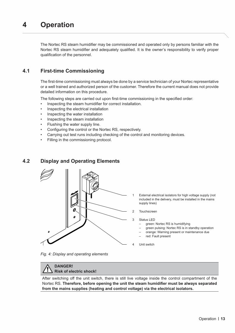
4.2 Display and Operating Elements
Fig. 4: Display and operating elements
DANGER!Risk of electric shock!
After switching off the unit switch, there is still live voltage inside the control compartment of the Nortec RS.Therefore,beforeopeningtheunitthesteamhumidifiermustbealwaysseparatedfrom the mains supplies (heating and control voltage) via the electrical isolators.
1 External electrical isolators for high voltage supply (not includ ed in the delivery, must be install ed in the mains supply lines)
2 Touchscreen
3 Status LED– green: Nortec RS is humidifying– green pulsing: Nortec RS is in standby operation– orange: Warning present or maintenance due– red: Fault present
4 Unit switch
Humidifier
14 Operation
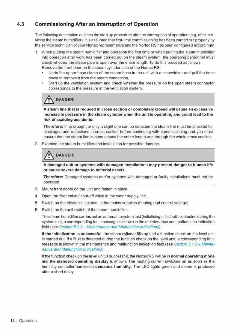
4.3 Commissioning After an Interruption of Operation
The following description outlines the start up procedure after an interruption of operation (e.g. after ser-vicing the steam humidifier). It is assumed that first-time commissioning has been carried out properly by the service technician of your Nortec representative and the Nortec RS has been configured accordingly.
1. When putting the steam humidifier into operation the first time or when putting the steam humidifier into operation after work has been carried out on the steam system, the operating personnel must check whether the steam pipe is open over the entire length. To do this proceed as follows: Remove the front door on the steam cylinder side of the Nortec RS.• Undo the upper hose clamp of the steam hose in the unit with a screwdriver and pull the hose
down to remove it from the steam connection. • Start up the ventilation system and check whether the pressure on the open steam connector
corresponds to the pressure in the ventilation system.
DANGER!
A steam line that is reduced in cross section or completely closed will cause an excessive increase in pressure in the steam cylinder when the unit is operating and could lead to the risk of scalding accidents! Therefore: If no draught or only a slight one can be detected the steam line must be checked for blockages and reductions in cross section before continuing with commissioning and you must ensure that the steam line is open across the entire length and through the whole cross section.
2. Examine the steam humidifier and installation for possible damage.
DANGER!
A damaged unit or systems with damaged installations may present danger to human life or cause severe damage to material assets. Therefore: Damaged systems and/or systems with damaged or faulty installations must not be operated.
3. Mount front doors on the unit and fasten in place.
4. Open the filter valve / shut-off valve in the water supply line.
5. Switch on the electrical isolators in the mains supplies (heating and control voltage).
6. Switch on the unit switch of the steam humidifier.
The steam humidifier carries out an automatic system test (initialising). If a fault is detected during the system test, a corresponding fault message is shown in the maintenance and malfunction indication field (see Section 5.1.2 – Maintenance and Malfunction Indications).
Iftheinitializationissuccessful, the steam cylinder fills up and a function check on the level unit is carried out. If a fault is detected during the function check on the level unit, a corresponding fault message is shown in the maintenance and malfunction indication field (see Section 5.1.2 – Mainte-nance and Malfunction Indications).
If the function check on the level unit is successful, the Nortec RS will be in normal operating mode and the standard operating display is shown. The heating current switches on as soon as the humidity controller/humidistat demands humidity. The LED lights green and steam is produced after a short delay.
15Operation
4.4 Notes on Operation
4.4.1 Inspections During Operation
During operation the Nortec RS and the humidification system have to be inspected weekly. This inspec-tion should consist of the following:
• checking the water and steam installation for any leakage.
• checking the steam humidifier and the other system components for proper mounting, and any dam-age.
• checking the electric installation for any damage.
If the inspection reveals any irregularities (e.g. leakages, error indication) or any damaged components, take the Nortec RS out of operation as described in Section 4.5 – Taking the Unit Out of Operation. Then contact your Nortec representative.
4.4.2 Manual Draining of the Steam Cylinder
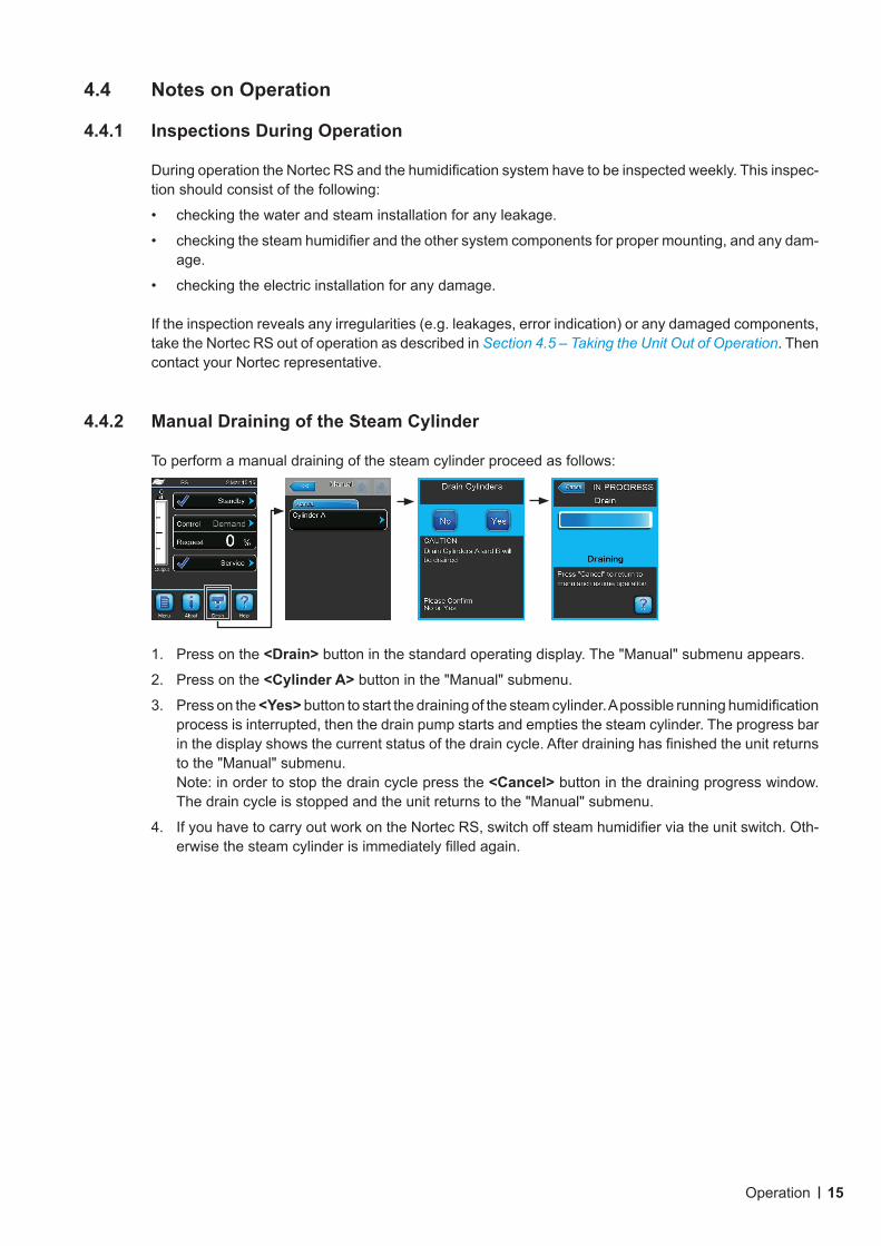
To perform a manual draining of the steam cylinder proceed as follows:
1. Press on the <Drain> button in the standard operating display. The "Manual" submenu appears.
2. Press on the <Cylinder A> button in the "Manual" submenu.
3. Press on the <Yes> button to start the draining of the steam cylinder. A possible running humidification process is interrupted, then the drain pump starts and empties the steam cylinder. The progress bar in the display shows the current status of the drain cycle. After draining has finished the unit returns to the "Manual" submenu.Note: in order to stop the drain cycle press the <Cancel> button in the draining progress window. The drain cycle is stopped and the unit returns to the "Manual" submenu.
4. If you have to carry out work on the Nortec RS, switch off steam humidifier via the unit switch. Oth-erwise the steam cylinder is immediately filled again.
16 Operation
4.5 Taking the Unit Out of Operation
In order to take the Nortec RS steam humidifier out of operation (e.g. for maintenance purpose), perform the following steps:
1. Close the shut-off valve in the water supply line.
2. If you have to carry out maintenance work on the steam cylinder and/or on the scale collector tank perform a manual draining (see Section 4.4.2 – Manual Draining of the Steam Cylinder).Note: On units equipped with the optional scale collector tank, the scale collector tank must be drained using the manually activated drain valve.
3. Switch off unit switch of the steam humidifier.
4. Disconnectsteamhumidifierfromthemains: Switch off electrical isolator in the mains supply line and secure switch in "Off" position against accidentally being switched on, or clearly mark the switch.
5. If you have to carry out maintenance work on the steam cylinder, empty the scale collector tank via the drain valve.
WARNING! Danger of burning!
The temperature of the water in the scale collector tank can be up to 203 °F (95 °C). Therefore: wear protective gloves and open the drain valve carefully.
If no water flows out from the open drain valve, the drain inside the scale collector tank is clogged and the scale collector tank may not be emptied. If this is the case, wait until the temperature indi-cation adhesive on the scale collector tank indicates a temperature below "<50°C" (<122°F) before dismantling the tank (since the scale collector tank is filled with water).
17Operating the Control Software
5 Operating the Control Software
5.1 Standard Operating Display
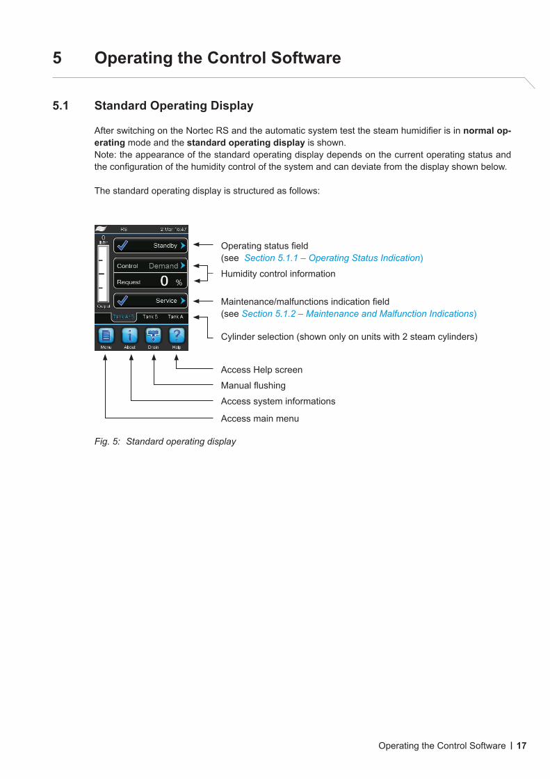
After switching on the Nortec RS and the automatic system test the steam humidifier is in normal op-erating mode and the standard operating display is shown.Note: the appearance of the standard operating display depends on the current operating status and the configuration of the humidity control of the system and can deviate from the display shown below.
The standard operating display is structured as follows:
Fig. 5: Standard operating display
Cylinder selection (shown only on units with 2 steam cylinders)
Maintenance/malfunctions indication field (see Section 5.1.2 – Maintenance and Malfunction Indications)
Humidity control information
Operating status field(see Section 5.1.1 – Operating Status Indication)
Access Help screen
Manual flushing
Access system informations
Access main menu
18 Operating the Control Software
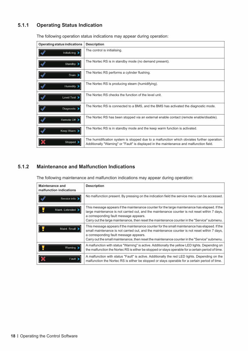
5.1.1 Operating Status Indication
The following operation status indications may appear during operation:
Operating status indications Description
The control is initialising.
The Nortec RS is in standby mode (no demand present).
The Nortec RS performs a cylinder flushing.
The Nortec RS is producing steam (humidifying).
The Nortec RS checks the function of the level unit.
The Nortec RS is connected to a BMS, and the BMS has activated the diagnostic mode.
The Nortec RS has been stopped via an external enable contact (remote enable/disable).
The Nortec RS is in standby mode and the keep warm function is activated.
The humidification system is stopped due to a malfunction which obviates further operation. Additionally "Warning" or "Fault" is displayed in the maintenance and malfunction field.
5.1.2 Maintenance and Malfunction Indications
The following maintenance and malfunction indications may appear during operation:
Maintenance and malfunction indications
Description
No malfunction present. By pressing on the indication field the service menu can be accessed.
This message appears if the maintenance counter for the large maintenance has elapsed. If the large maintenance is not carried out, and the maintenance counter is not reset within 7 days, a corresponding fault message appears.Carry out the large maintenance, then reset the maintenance counter in the "Service" submenu.
This message appears if the maintenance counter for the small maintenance has elapsed. If the small maintenance is not carried out, and the maintenance counter is not reset within 7 days, a corresponding fault message appears.Carry out the small maintenance, then reset the maintenance counter in the "Service" submenu.
A malfunction with status "Warning" is active. Additionally the yellow LED lights. Depending on the malfunction the Nortec RS is either be stopped or stays operable for a certain period of time.
A malfunction with status "Fault" is active. Additionally the red LED lights. Depending on the malfunction the Nortec RS is either be stopped or stays operable for a certain period of time.
19Operating the Control Software
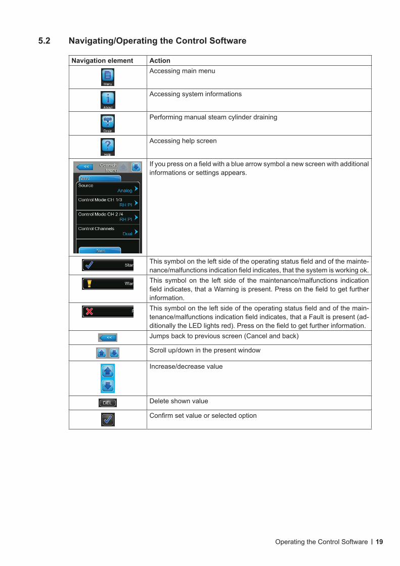
5.2 Navigating/Operating the Control Software
Navigation element ActionAccessing main menu
Accessing system informations
Performing manual steam cylinder draining
Accessing help screen
If you press on a field with a blue arrow symbol a new screen with additional informations or settings appears.
This symbol on the left side of the operating status field and of the mainte-nance/malfunctions indication field indicates, that the system is working ok.This symbol on the left side of the maintenance/malfunctions indication field indicates, that a Warning is present. Press on the field to get further information.This symbol on the left side of the operating status field and of the main-tenance/malfunctions indication field indicates, that a Fault is present (ad-ditionally the LED lights red). Press on the field to get further information.Jumps back to previous screen (Cancel and back)
Scroll up/down in the present window
Increase/decrease value
Delete shown value
Confirm set value or selected option
20 Operating the Control Software
5.3 Information Functions
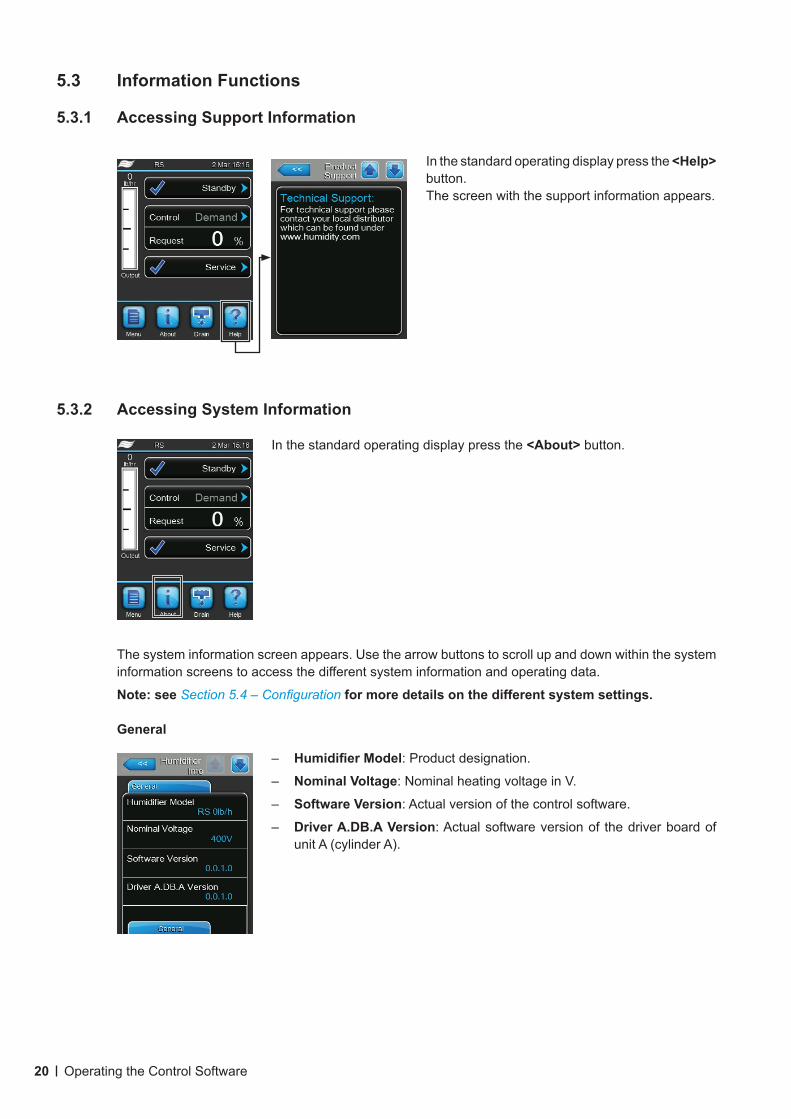
5.3.1 Accessing Support Information
In the standard operating display press the <Help> button.The screen with the support information appears.
5.3.2 Accessing System Information
In the standard operating display press the <About> button.
– HumidifierModel: Product designation.
– Nominal Voltage: Nominal heating voltage in V.
– Software Version: Actual version of the control software.
– Driver A.DB.A Version: Actual software version of the driver board of unit A (cylinder A).
The system information screen appears. Use the arrow buttons to scroll up and down within the system information screens to access the different system information and operating data.
Note: see Section 5.4 – Configuration for more details on the different system settings.
General
21Operating the Control Software
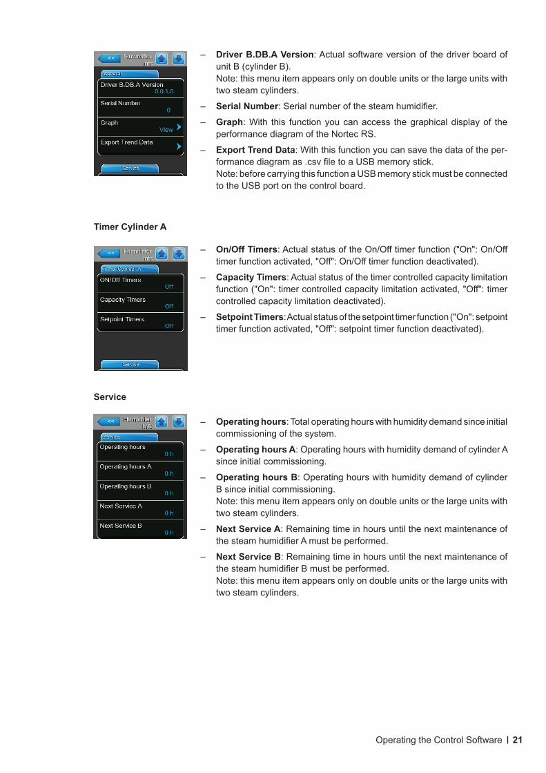
– Driver B.DB.A Version: Actual software version of the driver board of unit B (cylinder B).Note: this menu item appears only on double units or the large units with two steam cylinders.
– Serial Number: Serial number of the steam humidifier.
– Graph: With this function you can access the graphical display of the performance diagram of the Nortec RS.
– Export Trend Data: With this function you can save the data of the per-formance diagram as .csv file to a USB memory stick.Note: before carrying this function a USB memory stick must be connected to the USB port on the control board.
Timer Cylinder A
– On/Off Timers: Actual status of the On/Off timer function ("On": On/Off timer function activated, "Off": On/Off timer function deactivated).
– Capacity Timers: Actual status of the timer controlled capacity limitation function ("On": timer controlled capacity limitation activated, "Off": timer controlled capacity limitation deactivated).
– Setpoint Timers: Actual status of the setpoint timer function ("On": setpoint timer function activated, "Off": setpoint timer function deactivated).
Service
– Operating hours: Total operating hours with humidity demand since initial commissioning of the system.
– Operating hours A: Operating hours with humidity demand of cylinder A since initial commissioning.
– Operating hours B: Operating hours with humidity demand of cylinder B since initial commissioning.Note: this menu item appears only on double units or the large units with two steam cylinders.
– Next Service A: Remaining time in hours until the next maintenance of the steam humidifier A must be performed.
– Next Service B: Remaining time in hours until the next maintenance of the steam humidifier B must be performed.Note: this menu item appears only on double units or the large units with two steam cylinders.
22 Operating the Control Software
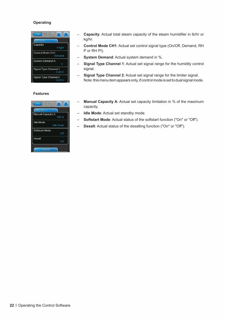
Operating
– Capacity: Actual total steam capacity of the steam humidifier in lb/hr or kg/hr.
– Control Mode CH1: Actual set control signal type (On/Off, Demand, RH P or RH PI).
– System Demand: Actual system demand in %.
– Signal Type Channel 1: Actual set signal range for the humidity control signal.
– Signal Type Channel 2: Actual set signal range for the limiter signal.Note: this menu item appears only, if control mode is set to dual signal mode.
Features
– Manual Capacity A: Actual set capacity limitation in % of the maximum capacity.
– Idle Mode: Actual set standby mode.
– Softstart Mode: Actual status of the softstart function ("On" or "Off").
– Desalt: Actual status of the desalting function ("On" or "Off").
23Operating the Control Software
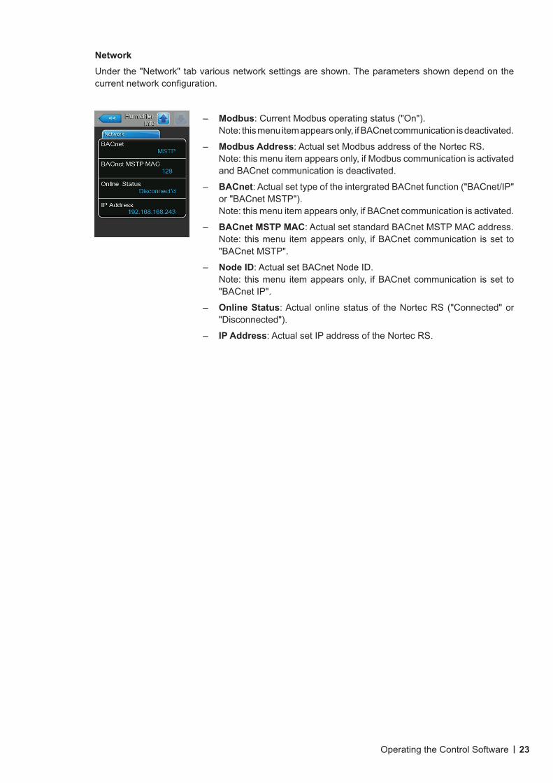
NetworkUnder the "Network" tab various network settings are shown. The parameters shown depend on the current network configuration.
– Modbus: Current Modbus operating status ("On").Note: this menu item appears only, if BACnet communication is deactivated.
– Modbus Address: Actual set Modbus address of the Nortec RS.Note: this menu item appears only, if Modbus communication is activated and BACnet communication is deactivated.
– BACnet: Actual set type of the intergrated BACnet function ("BACnet/IP" or "BACnet MSTP"). Note: this menu item appears only, if BACnet communication is activated.
– BACnet MSTP MAC: Actual set standard BACnet MSTP MAC address.Note: this menu item appears only, if BACnet communication is set to "BACnet MSTP".
– Node ID: Actual set BACnet Node ID.Note: this menu item appears only, if BACnet communication is set to "BACnet IP".
– Online Status: Actual online status of the Nortec RS ("Connected" or "Disconnected").
– IP Address: Actual set IP address of the Nortec RS.
24 Operating the Control Software
5.4 Configuration
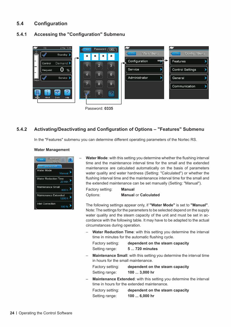
5.4.1 Accessingthe"Configuration"Submenu
5.4.2 Activating/DeactivatingandConfigurationofOptions–"Features"Submenu
In the "Features" submenu you can determine different operating parameters of the Nortec RS.
Water Management
– Water Mode: with this setting you determine whether the flushing interval time and the maintenance interval time for the small and the extended maintenance are calculated automatically on the basis of parameters water quality and water hardness (Setting: "Calculated") or whether the flushing interval time and the maintenance interval time for the small and the extended maintenance can be set manually (Setting: "Manual").Factory setting: ManualOptions: Manual or Calculated
The following settings appear only, if "Water Mode" is set to "Manual".Note: The settings for the parameters to be selected depend on the supply water quality and the steam capacity of the unit and must be set in ac-cordance with the following table. It may have to be adapted to the actual circumstances during operation.
– Water Reduction Time: with this setting you determine the interval time in minutes for the automatic flushing cycle.Factory setting: dependent on the steam capacitySetting range: 5 ... 720 minutes
– Maintenance Small: with this setting you determine the interval time in hours for the small maintenance.Factory setting: dependent on the steam capacitySetting range: 100 ... 3,000 hr
– Maintenance Extended: with this setting you determine the interval time in hours for the extended maintenance.Factory setting: dependent on the steam capacitySetting range: 100 ... 6,000 hr
Password: 0335
25Operating the Control Software
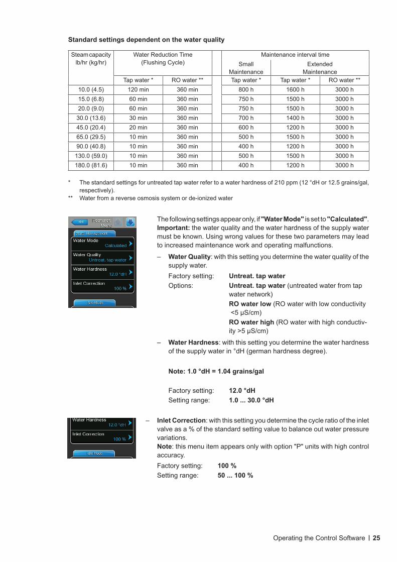
Standard settings dependent on the water quality
Steam capacity lb/hr (kg/hr)
Water Reduction Time(Flushing Cycle)
Maintenance interval timeSmall
MaintenanceExtended
MaintenanceTap water * RO water ** Tap water * Tap water * RO water **
10.0 (4.5) 120 min 360 min 800 h 1600 h 3000 h15.0 (6.8) 60 min 360 min 750 h 1500 h 3000 h20.0 (9.0) 60 min 360 min 750 h 1500 h 3000 h
30.0 (13.6) 30 min 360 min 700 h 1400 h 3000 h45.0 (20.4) 20 min 360 min 600 h 1200 h 3000 h65.0 (29.5) 10 min 360 min 500 h 1500 h 3000 h90.0 (40.8) 10 min 360 min 400 h 1200 h 3000 h
130.0 (59.0) 10 min 360 min 500 h 1500 h 3000 h180.0 (81.6) 10 min 360 min 400 h 1200 h 3000 h
* The standard settings for untreated tap water refer to a water hardness of 210 ppm (12 °dH or 12.5 grains/gal, respectively).
** Water from a reverse osmosis system or de-ionized water
The following settings appear only, if "Water Mode" is set to "Calculated".Important: the water quality and the water hardness of the supply water must be known. Using wrong values for these two parameters may lead to increased maintenance work and operating malfunctions.
– Water Quality: with this setting you determine the water quality of the supply water.Factory setting: Untreat. tap waterOptions: Untreat. tap water (untreated water from tap
water network) RO water low (RO water with low conductivity
<5 µS/cm) RO water high (RO water with high conductiv-
ity >5 µS/cm)
– Water Hardness: with this setting you determine the water hardness of the supply water in °dH (german hardness degree).
Note: 1.0 °dH = 1.04 grains/gal
Factory setting: 12.0 °dHSetting range: 1.0 ... 30.0 °dH
– Inlet Correction: with this setting you determine the cycle ratio of the inlet valve as a % of the standard setting value to balance out water pressure variations.Note: this menu item appears only with option "P" units with high control accuracy.Factory setting: 100 %Setting range: 50 ... 100 %
26 Operating the Control Software
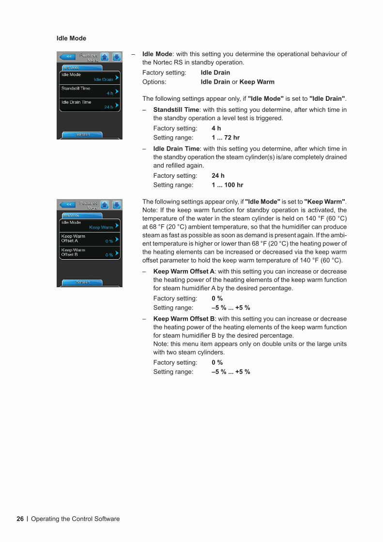
– Idle Mode: with this setting you determine the operational behaviour of the Nortec RS in standby operation. Factory setting: Idle DrainOptions: Idle Drain or Keep Warm
The following settings appear only, if "Idle Mode" is set to "Idle Drain".
– Standstill Time: with this setting you determine, after which time in the standby operation a level test is triggered.Factory setting: 4 hSetting range: 1 ... 72 hr
– Idle Drain Time: with this setting you determine, after which time in the standby operation the steam cylinder(s) is/are completely drained and refilled again.Factory setting: 24 hSetting range: 1 ... 100 hr
The following settings appear only, if "Idle Mode" is set to "Keep Warm".Note: If the keep warm function for standby operation is activated, the temperature of the water in the steam cylinder is held on 140 °F (60 °C) at 68 °F (20 °C) ambient temperature, so that the humidifier can produce steam as fast as possible as soon as demand is present again. If the ambi-ent temperature is higher or lower than 68 °F (20 °C) the heating power of the heating elements can be increased or decreased via the keep warm offset parameter to hold the keep warm temperature of 140 °F (60 °C).
– Keep Warm Offset A: with this setting you can increase or decrease the heating power of the heating elements of the keep warm function for steam humidifier A by the desired percentage.Factory setting: 0 %Setting range: –5%...+5%
– Keep Warm Offset B: with this setting you can increase or decrease the heating power of the heating elements of the keep warm function for steam humidifier B by the desired percentage.Note: this menu item appears only on double units or the large units with two steam cylinders.Factory setting: 0 %Setting range: –5%...+5%
Idle Mode

27Operating the Control Software
Softstart
– Softstart Mode: with this setting you can activate ("On") or deactivate ("Off") the softstart function.Factory setting: OffOptions: On or OffNote: activate the soft start function if you are using softened water or water with a high conductivity.
Note: if the softstart function is activated the humidification capacity is reduced to a preset value for a select able period if a demand is present after restarting the steam humidifier or after more than 4 hours in standby operation (settings see parameters below).
The following settings appear only, if "Softstart Mode" is set to "On".
– Softstart Time: with this setting you determine how long the softstart functions should remain activated in minutes.Factory setting: 30 minutesSetting range: 10 ... 120 minutes
– Softstart Power: with this setting you determine the capacity limitation for the softstart function in % of the maximum capacity of the humidi-fier.Factory setting: 75 %Setting range: 4 ... 100 %
Desalt Mode
– Desalt Mode: with this setting you can activate ("On") or deactivate ("Off") the demineralisation mode.Factory setting: OffOptions: On or OffNote: enable the demineralization mode if you are using softened water or water with a high conductivity.
Note: if desalting mode is activated the steam cylinder is drained after the set foam detection counts (see following parameter "Water Desalt Counts") within an hour is reached. Thus preventing the formation of foam in the steam cylinder.
The following setting appears only, if "Desalt Mode" is set to "On".
– Water Desalt Counts: with this setting you determine how many times the maximum level in the steam cylinder can be reached within on hour (foam detection) before a time-controlled flushing cycle will be initiated.Factory setting: 3Setting range: 1 ... 8
28 Operating the Control Software
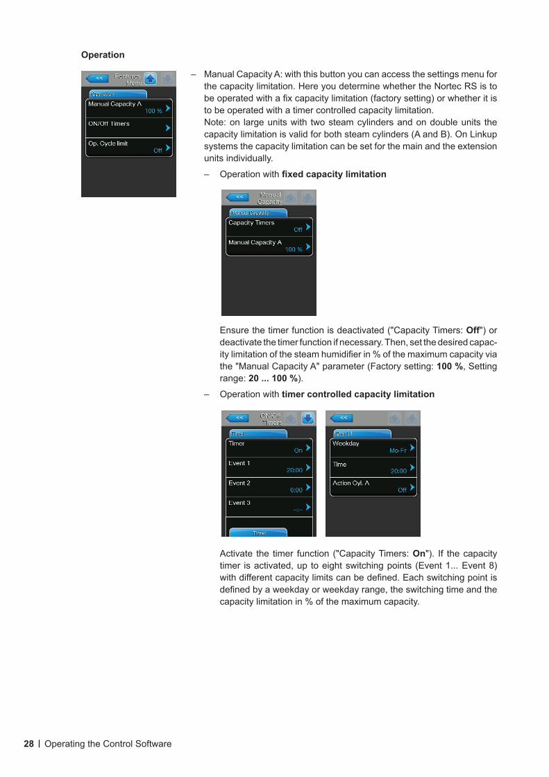
Operation
– Manual Capacity A: with this button you can access the settings menu for the capacity limitation. Here you determine whether the Nortec RS is to be operated with a fix capacity limitation (factory setting) or whether it is to be operated with a timer controlled capacity limitation.Note: on large units with two steam cylinders and on double units the capacity limitation is valid for both steam cylinders (A and B). On Linkup systems the capacity limitation can be set for the main and the extension units individually.
– Operation with fixedcapacitylimitation
Ensure the timer function is deactivated ("Capacity Timers: Off") or deactivate the timer function if necessary. Then, set the desired capac-ity limitation of the steam humidifier in % of the maximum capacity via the "Manual Capacity A" parameter (Factory setting: 100 %, Setting range: 20 ... 100 %).
– Operation with timer controlled capacity limitation
Activate the timer function ("Capacity Timers: On"). If the capacity timer is activated, up to eight switching points (Event 1... Event 8) with different capacity limits can be defined. Each switching point is defined by a weekday or weekday range, the switching time and the capacity limitation in % of the maximum capacity.
29Operating the Control Software
Configuration notes: – the settings of an event remain active up to the next event.– the software does not check the plausibility of the timer settings.
Therefore, make sure your settings make sense.– the On/Off timer overrides the capacity limit timer.
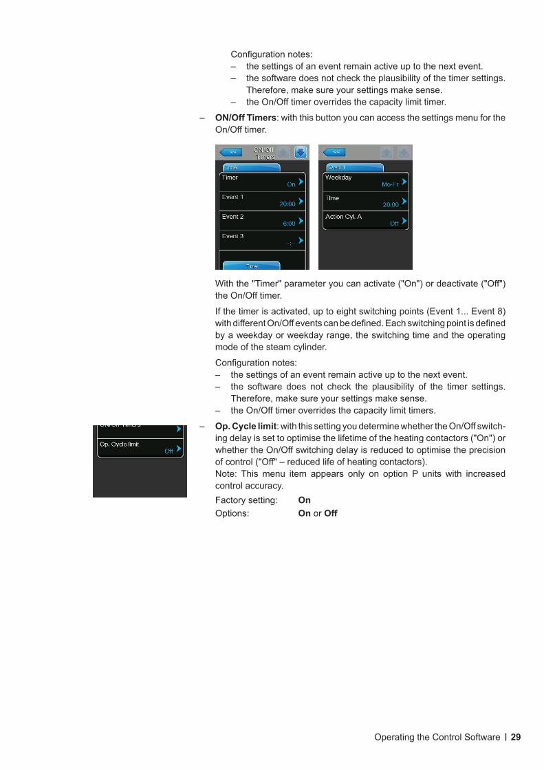
– ON/Off Timers: with this button you can access the settings menu for the On/Off timer.
With the "Timer" parameter you can activate ("On") or deactivate ("Off") the On/Off timer.
If the timer is activated, up to eight switching points (Event 1... Event 8) with different On/Off events can be defined. Each switching point is defined by a weekday or weekday range, the switching time and the operating mode of the steam cylinder.
Configuration notes: – the settings of an event remain active up to the next event.– the software does not check the plausibility of the timer settings.
Therefore, make sure your settings make sense.– the On/Off timer overrides the capacity limit timers.
– Op. Cycle limit: with this setting you determine whether the On/Off switch-ing delay is set to optimise the lifetime of the heating contactors ("On") or whether the On/Off switching delay is reduced to optimise the precision of control ("Off" – reduced life of heating contactors).Note: This menu item appears only on option P units with increased control accuracy.Factory setting: OnOptions: On or Off
30 Operating the Control Software
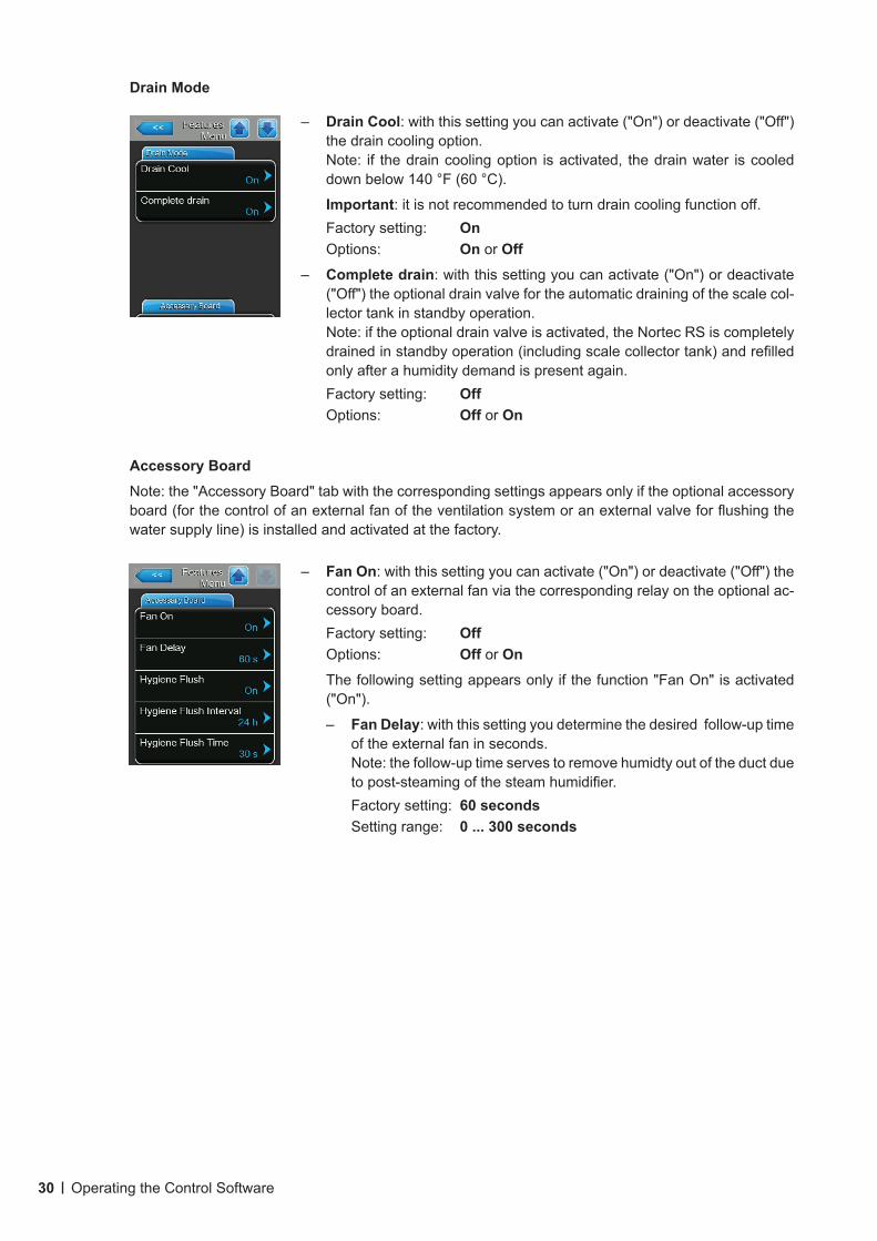
Drain Mode
– Drain Cool: with this setting you can activate ("On") or deactivate ("Off") the drain cooling option.Note: if the drain cooling option is activated, the drain water is cooled down below 140 °F (60 °C).
Important: it is not recommended to turn drain cooling function off.Factory setting: OnOptions: On or Off
– Complete drain: with this setting you can activate ("On") or deactivate ("Off") the optional drain valve for the automatic draining of the scale col-lector tank in standby operation.Note: if the optional drain valve is activated, the Nortec RS is completely drained in standby operation (including scale collector tank) and refilled only after a humidity demand is present again.Factory setting: OffOptions: Off or On
– Fan On: with this setting you can activate ("On") or deactivate ("Off") the control of an external fan via the corresponding relay on the optional ac-cessory board.Factory setting: OffOptions: Off or OnThe following setting appears only if the function "Fan On" is activated ("On").
– Fan Delay: with this setting you determine the desired follow-up time of the external fan in seconds.Note: the follow-up time serves to remove humidty out of the duct due to post-steaming of the steam humidifier.Factory setting: 60 secondsSetting range: 0 ... 300 seconds
Accessory BoardNote: the "Accessory Board" tab with the corresponding settings appears only if the optional accessory board (for the control of an external fan of the ventilation system or an external valve for flushing the water supply line) is installed and activated at the factory.
31Operating the Control Software
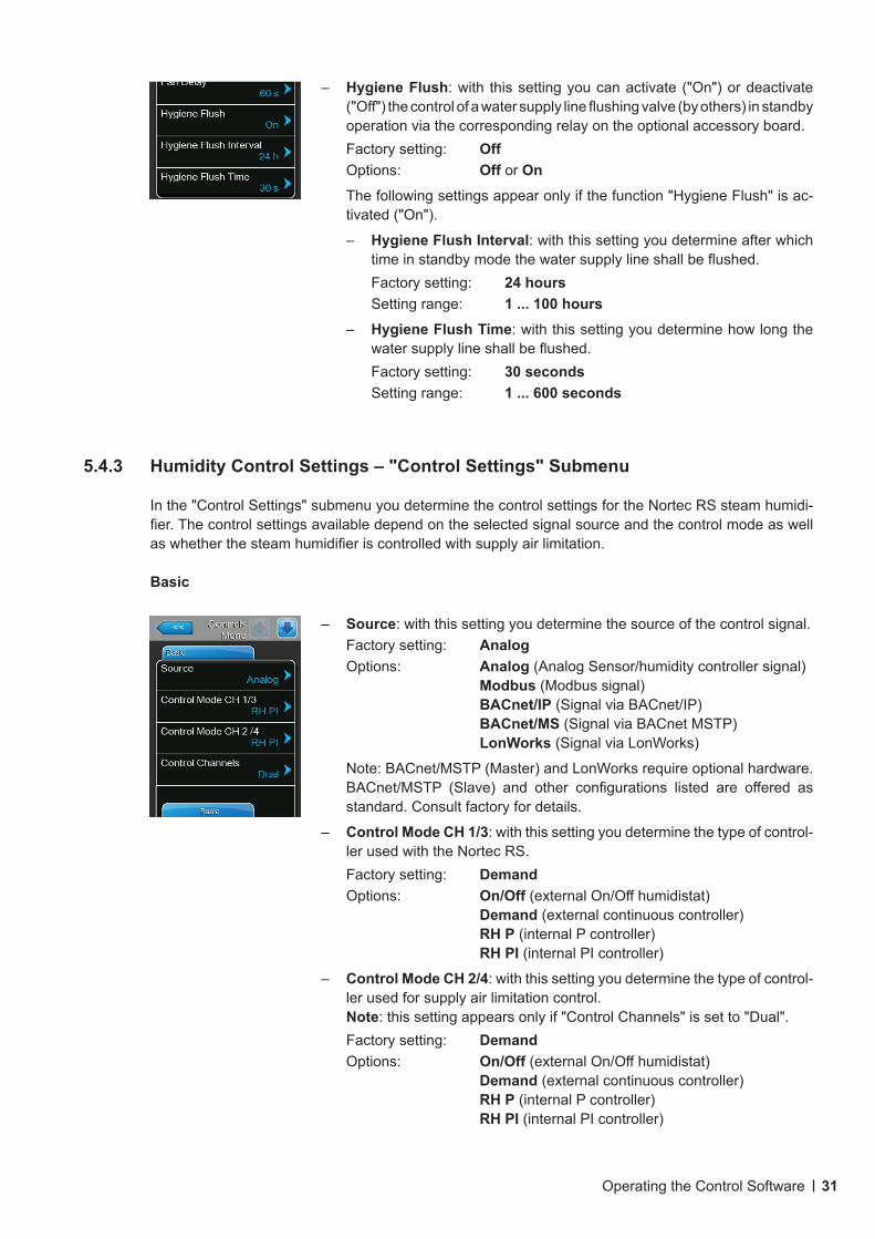
– Hygiene Flush: with this setting you can activate ("On") or deactivate ("Off") the control of a water supply line flushing valve (by others) in standby operation via the corresponding relay on the optional accessory board.Factory setting: OffOptions: Off or OnThe following settings appear only if the function "Hygiene Flush" is ac-tivated ("On").
– Hygiene Flush Interval: with this setting you determine after which time in standby mode the water supply line shall be flushed.Factory setting: 24 hoursSetting range: 1 ... 100 hours
– Hygiene Flush Time: with this setting you determine how long the water supply line shall be flushed.Factory setting: 30 secondsSetting range: 1 ... 600 seconds
5.4.3 HumidityControlSettings–"ControlSettings"Submenu
In the "Control Settings" submenu you determine the control settings for the Nortec RS steam humidi-fier. The control settings available depend on the selected signal source and the control mode as well as whether the steam humidifier is controlled with supply air limitation.
Basic
– Source: with this setting you determine the source of the control signal.Factory setting: AnalogOptions: Analog (Analog Sensor/humidity controller signal)
Modbus (Modbus signal) BACnet/IP (Signal via BACnet/IP) BACnet/MS (Signal via BACnet MSTP) LonWorks (Signal via LonWorks)
Note: BACnet/MSTP (Master) and LonWorks require optional hardware. BACnet/MSTP (Slave) and other configurations listed are offered as standard. Consult factory for details.
– Control Mode CH 1/3: with this setting you determine the type of control-ler used with the Nortec RS.Factory setting: DemandOptions: On/Off (external On/Off humidistat)
Demand (external continuous controller) RH P (internal P controller) RH PI (internal PI controller)
– Control Mode CH 2/4: with this setting you determine the type of control-ler used for supply air limitation control.Note: this setting appears only if "Control Channels" is set to "Dual".Factory setting: DemandOptions: On/Off (external On/Off humidistat)
Demand (external continuous controller) RH P (internal P controller) RH PI (internal PI controller)
32 Operating the Control Software
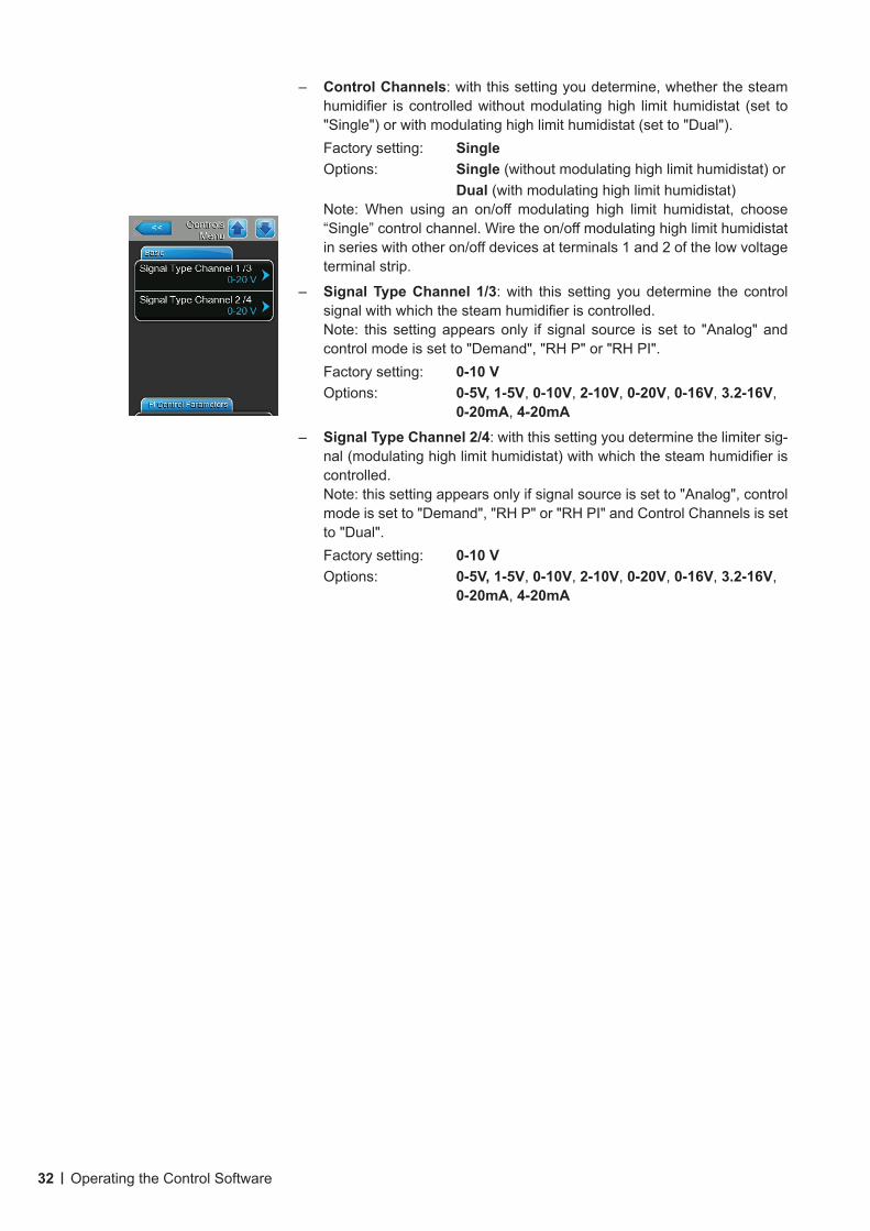
– Control Channels: with this setting you determine, whether the steam humidifier is controlled without modulating high limit humidistat (set to "Single") or with modulating high limit humidistat (set to "Dual").Factory setting: SingleOptions: Single (without modulating high limit humidistat) or Dual (with modulating high limit humidistat) Note: When using an on/off modulating high limit humidistat, choose “Single” control channel. Wire the on/off modulating high limit humidistat in series with other on/off devices at terminals 1 and 2 of the low voltage terminal strip.
– Signal Type Channel 1/3: with this setting you determine the control signal with which the steam humidifier is controlled.Note: this setting appears only if signal source is set to "Analog" and control mode is set to "Demand", "RH P" or "RH PI".Factory setting: 0-10 VOptions: 0-5V, 1-5V, 0-10V, 2-10V, 0-20V, 0-16V, 3.2-16V,
0-20mA, 4-20mA
– Signal Type Channel 2/4: with this setting you determine the limiter sig-nal (modulating high limit humidistat) with which the steam humidifier is controlled.Note: this setting appears only if signal source is set to "Analog", control mode is set to "Demand", "RH P" or "RH PI" and Control Channels is set to "Dual".Factory setting: 0-10 VOptions: 0-5V, 1-5V, 0-10V, 2-10V, 0-20V, 0-16V, 3.2-16V,
0-20mA, 4-20mA
33Operating the Control Software
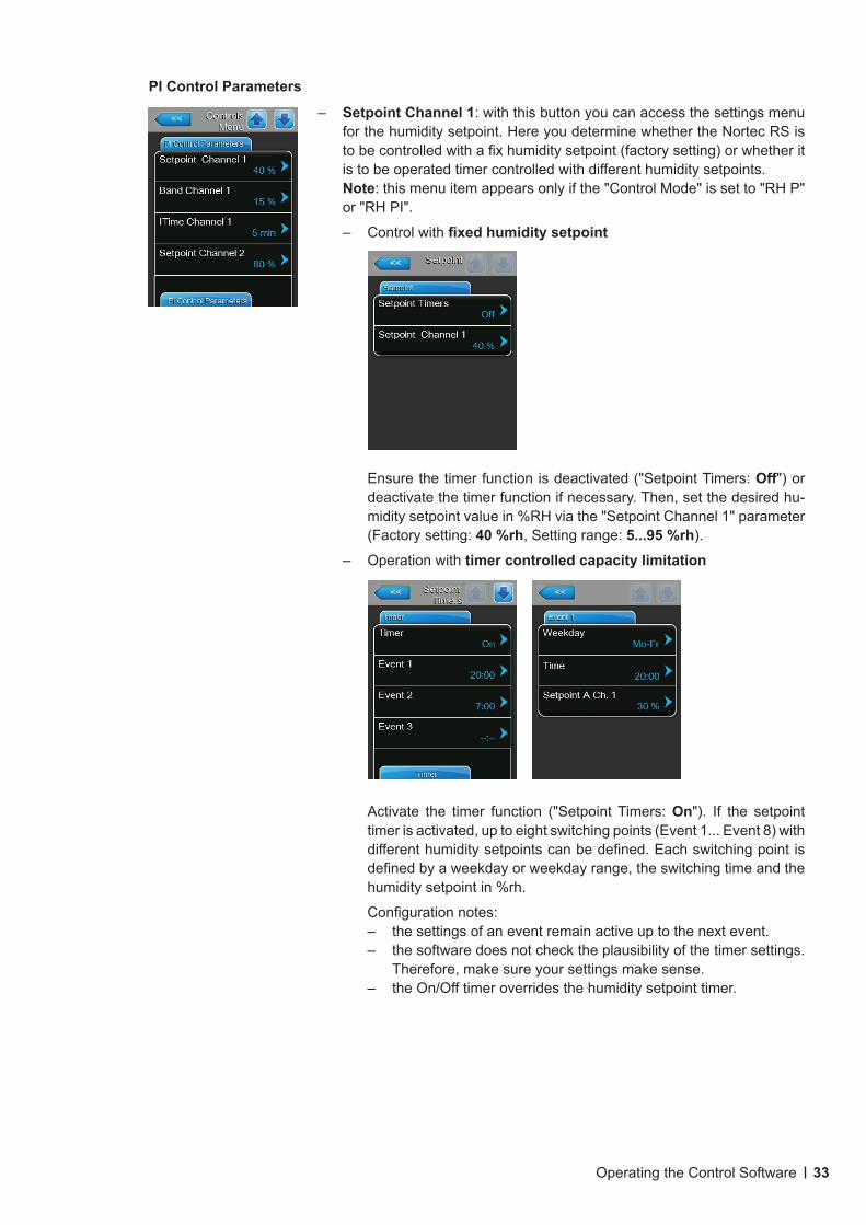
PI Control Parameters
– Setpoint Channel 1: with this button you can access the settings menu for the humidity setpoint. Here you determine whether the Nortec RS is to be controlled with a fix humidity setpoint (factory setting) or whether it is to be operated timer controlled with different humidity setpoints.Note: this menu item appears only if the "Control Mode" is set to "RH P" or "RH PI".
– Control with fixedhumiditysetpoint
Ensure the timer function is deactivated ("Setpoint Timers: Off") or deactivate the timer function if necessary. Then, set the desired hu-midity setpoint value in %RH via the "Setpoint Channel 1" parameter (Factory setting: 40 %rh, Setting range: 5...95 %rh).
– Operation with timer controlled capacity limitation
Activate the timer function ("Setpoint Timers: On"). If the setpoint timer is activated, up to eight switching points (Event 1... Event 8) with different humidity setpoints can be defined. Each switching point is defined by a weekday or weekday range, the switching time and the humidity setpoint in %rh.
Configuration notes: – the settings of an event remain active up to the next event.– the software does not check the plausibility of the timer settings.
Therefore, make sure your settings make sense.– the On/Off timer overrides the humidity setpoint timer.
34 Operating the Control Software
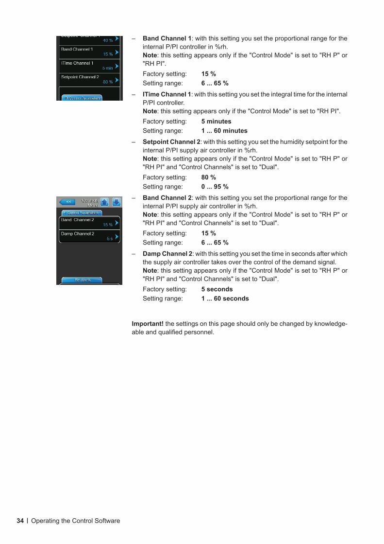
– Band Channel 1: with this setting you set the proportional range for the internal P/PI controller in %rh.Note: this setting appears only if the "Control Mode" is set to "RH P" or "RH PI".Factory setting: 15 %Setting range: 6 ... 65 %
– ITime Channel 1: with this setting you set the integral time for the internal P/PI controller.Note: this setting appears only if the "Control Mode" is set to "RH PI".Factory setting: 5 minutesSetting range: 1 ... 60 minutes
– Setpoint Channel 2: with this setting you set the humidity setpoint for the internal P/PI supply air controller in %rh.Note: this setting appears only if the "Control Mode" is set to "RH P" or "RH PI" and "Control Channels" is set to "Dual".Factory setting: 80 %Setting range: 0 ... 95 %
– Band Channel 2: with this setting you set the proportional range for the internal P/PI supply air controller in %rh.Note: this setting appears only if the "Control Mode" is set to "RH P" or "RH PI" and "Control Channels" is set to "Dual".Factory setting: 15 %Setting range: 6 ... 65 %
– Damp Channel 2: with this setting you set the time in seconds after which the supply air controller takes over the control of the demand signal.Note: this setting appears only if the "Control Mode" is set to "RH P" or "RH PI" and "Control Channels" is set to "Dual".Factory setting: 5 secondsSetting range: 1 ... 60 seconds
Important! the settings on this page should only be changed by knowledge-able and qualified personnel.
35Operating the Control Software
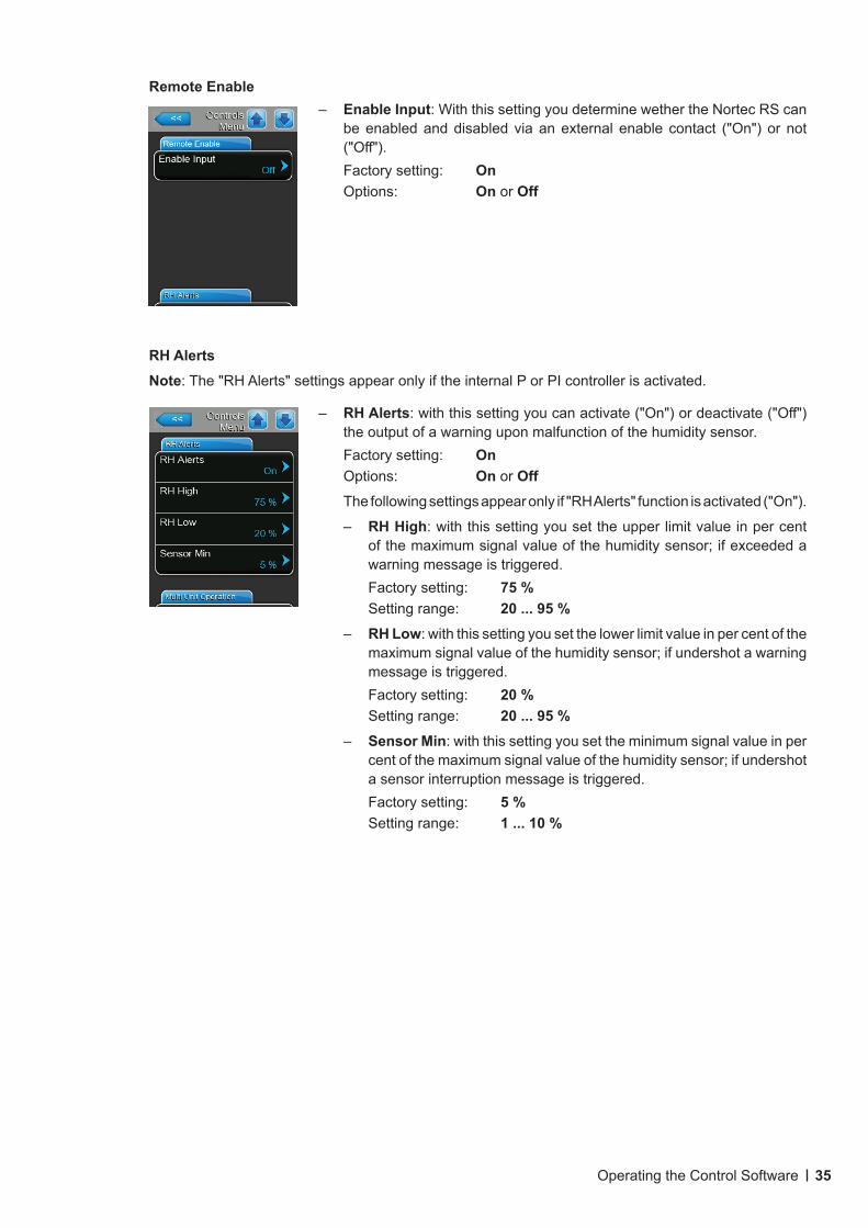
Remote Enable– Enable Input: With this setting you determine wether the Nortec RS can
be enabled and disabled via an external enable contact ("On") or not ("Off"). Factory setting: OnOptions: On or Off
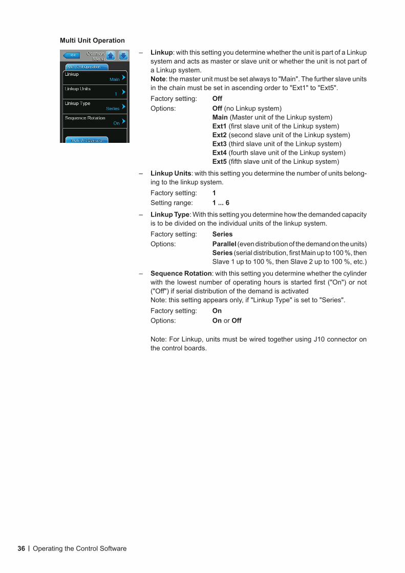
RH AlertsNote: The "RH Alerts" settings appear only if the internal P or PI controller is activated.
– RH Alerts: with this setting you can activate ("On") or deactivate ("Off") the output of a warning upon malfunction of the humidity sensor.Factory setting: OnOptions: On or OffThe following settings appear only if "RH Alerts" function is activated ("On").
– RH High: with this setting you set the upper limit value in per cent of the maximum signal value of the humidity sensor; if exceeded a warning message is triggered.Factory setting: 75 %Setting range: 20 ... 95 %
– RH Low: with this setting you set the lower limit value in per cent of the maximum signal value of the humidity sensor; if undershot a warning message is triggered.Factory setting: 20 %Setting range: 20 ... 95 %
– Sensor Min: with this setting you set the minimum signal value in per cent of the maximum signal value of the humidity sensor; if undershot a sensor interruption message is triggered.Factory setting: 5 %Setting range: 1 ... 10 %
36 Operating the Control Software
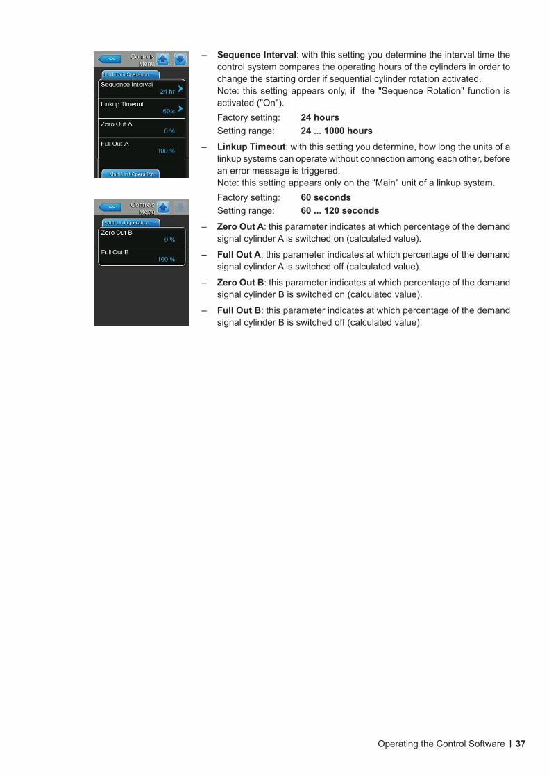
Multi Unit Operation
– Linkup: with this setting you determine whether the unit is part of a Linkup system and acts as master or slave unit or whether the unit is not part of a Linkup system.Note: the master unit must be set always to "Main". The further slave units in the chain must be set in ascending order to "Ext1" to "Ext5".Factory setting: Off Options: Off (no Linkup system)
Main (Master unit of the Linkup system) Ext1 (first slave unit of the Linkup system) Ext2 (second slave unit of the Linkup system) Ext3 (third slave unit of the Linkup system) Ext4 (fourth slave unit of the Linkup system) Ext5 (fifth slave unit of the Linkup system)
– Linkup Units: with this setting you determine the number of units belong-ing to the linkup system.Factory setting: 1Setting range: 1 ... 6
– Linkup Type: With this setting you determine how the demanded capacity is to be divided on the individual units of the linkup system.Factory setting: SeriesOptions: Parallel (even distribution of the demand on the units)
Series (serial distribution, first Main up to 100 %, then Slave 1 up to 100 %, then Slave 2 up to 100 %, etc.)
– Sequence Rotation: with this setting you determine whether the cylinder with the lowest number of operating hours is started first ("On") or not ("Off") if serial distribution of the demand is activatedNote: this setting appears only, if "Linkup Type" is set to "Series".Factory setting: OnOptions: On or Off
Note: For Linkup, units must be wired together using J10 connector on the control boards.
37Operating the Control Software
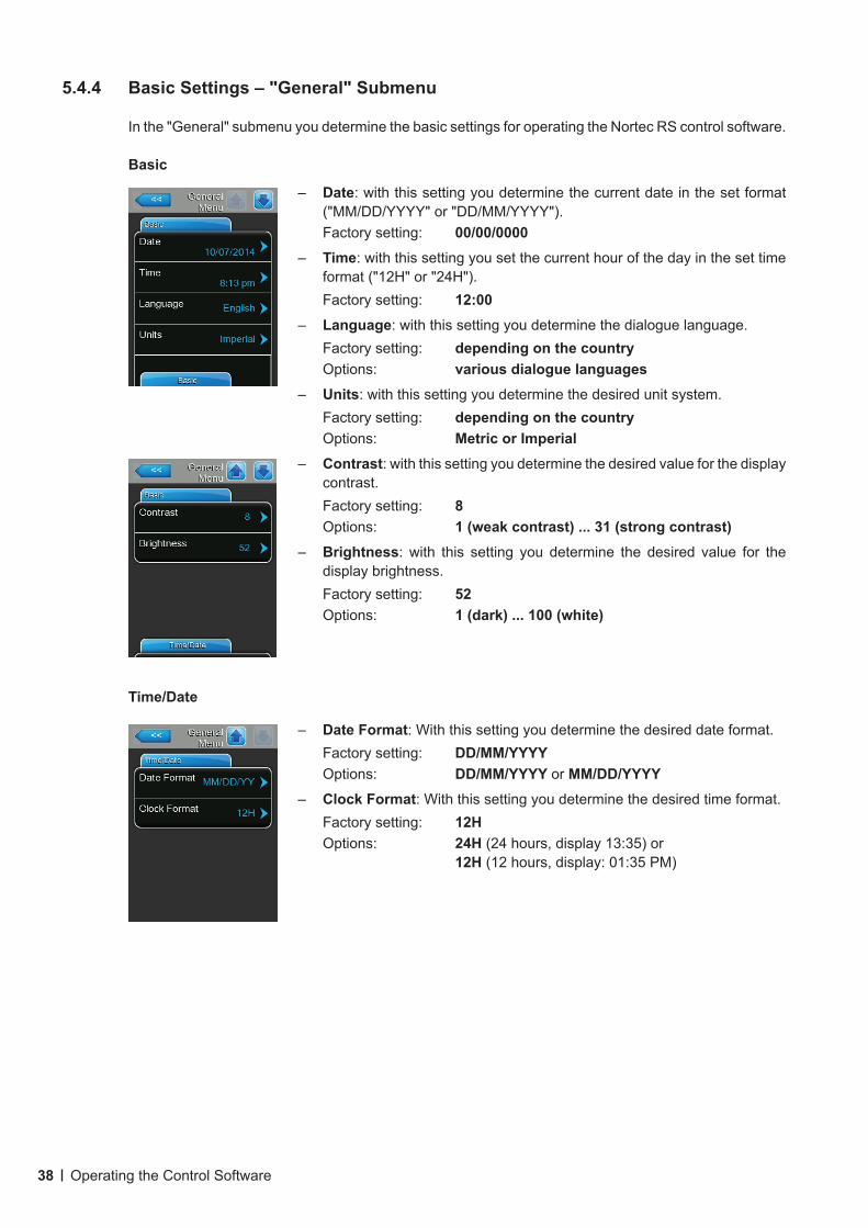
– Sequence Interval: with this setting you determine the interval time the control system compares the operating hours of the cylinders in order to change the starting order if sequential cylinder rotation activated. Note: this setting appears only, if the "Sequence Rotation" function is activated ("On").Factory setting: 24 hoursSetting range: 24 ... 1000 hours
– Linkup Timeout: with this setting you determine, how long the units of a linkup systems can operate without connection among each other, before an error message is triggered. Note: this setting appears only on the "Main" unit of a linkup system.Factory setting: 60 secondsSetting range: 60 ... 120 seconds
– Zero Out A: this parameter indicates at which percentage of the demand signal cylinder A is switched on (calculated value).
– Full Out A: this parameter indicates at which percentage of the demand signal cylinder A is switched off (calculated value).
– Zero Out B: this parameter indicates at which percentage of the demand signal cylinder B is switched on (calculated value).
– Full Out B: this parameter indicates at which percentage of the demand signal cylinder B is switched off (calculated value).
38 Operating the Control Software
5.4.4 BasicSettings–"General"Submenu
In the "General" submenu you determine the basic settings for operating the Nortec RS control software.
Basic
– Date: with this setting you determine the current date in the set format ("MM/DD/YYYY" or "DD/MM/YYYY").Factory setting: 00/00/0000
– Time: with this setting you set the current hour of the day in the set time format ("12H" or "24H").Factory setting: 12:00
– Language: with this setting you determine the dialogue language.Factory setting: depending on the countryOptions: various dialogue languages
– Units: with this setting you determine the desired unit system.Factory setting: depending on the countryOptions: Metric or Imperial
– Contrast: with this setting you determine the desired value for the display contrast.Factory setting: 8Options: 1 (weak contrast) ... 31 (strong contrast)
– Brightness: with this setting you determine the desired value for the display brightness.Factory setting: 52Options: 1 (dark) ... 100 (white)
Time/Date
– Date Format: With this setting you determine the desired date format.Factory setting: DD/MM/YYYYOptions: DD/MM/YYYY or MM/DD/YYYY
– Clock Format: With this setting you determine the desired time format.Factory setting: 12HOptions: 24H (24 hours, display 13:35) or
12H (12 hours, display: 01:35 PM)
39Operating the Control Software
5.4.5 CommunicationSettings–"Communication"Submenu
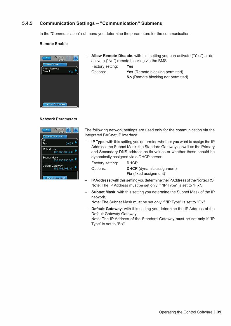
In the "Communication" submenu you determine the parameters for the communication.
Remote Enable
Network Parameters
The following network settings are used only for the communication via the integrated BACnet IP interface.
– IP Type: with this setting you determine whether you want to assign the IP Address, the Subnet Mask, the Standard Gateway as well as the Primary and Secondary DNS address as fix values or whether these should be dynamically assigned via a DHCP server.Factory setting: DHCPOptions: DHCP (dynamic assignment)
Fix (fixed assignment)
– IP Address: with this setting you determine the IP Address of the Nortec RS.Note: The IP Address must be set only if "IP Type" is set to "Fix".
– Subnet Mask: with this setting you determine the Subnet Mask of the IP network.Note: The Subnet Mask must be set only if "IP Type" is set to "Fix".
– Default Gateway: with this setting you determine the IP Address of the Default Gateway Gateway.Note: The IP Address of the Standard Gateway must be set only if "IP Type" is set to "Fix".
– Allow Remote Disable: with this setting you can activate ("Yes") or de-activate ("No") remote blocking via the BMS.Factory setting: YesOptions: Yes (Remote blocking permitted)
No (Remote blocking not permitted)
40 Operating the Control Software
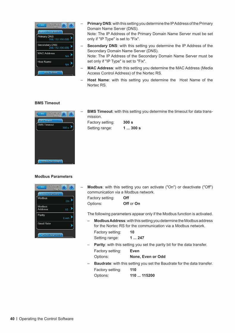
– Primary DNS: with this setting you determine the IP Address of the Primary Domain Name Server (DNS).Note: The IP Address of the Primary Domain Name Server must be set only if "IP Type" is set to "Fix".
– Secondary DNS: with this setting you determine the IP Address of the Secondary Domain Name Server (DNS).Note: The IP Address of the Secondary Domain Name Server must be set only if "IP Type" is set to "Fix".
– MAC Address: with this setting you determine the MAC Address (Media Access Control Address) of the Nortec RS.
– Host Name: with this setting you determine the Host Name of the Nortec RS.
BMS Timeout
– BMS Timeout: with this setting you determine the timeout for data trans-mission.Factory setting: 300 sSetting range: 1 ... 300 s
Modbus Parameters
– Modbus: with this setting you can activate ("On") or deactivate ("Off") communication via a Modbus network.Factory setting: OffOptions: Off or On
The following parameters appear only if the Modbus function is activated.
– Modbus Address: with this setting you determine the Modbus address for the Nortec RS for the communication via a Modbus network.Factory setting: 10Setting range: 1 ... 247
– Parity: with this setting you set the parity bit for the data transfer.Factory setting: EvenOptions: None, Even or Odd
– Baudrate: with this setting you set the Baudrate for the data transfer.Factory setting: 110Options: 110 ... 115200
41Operating the Control Software
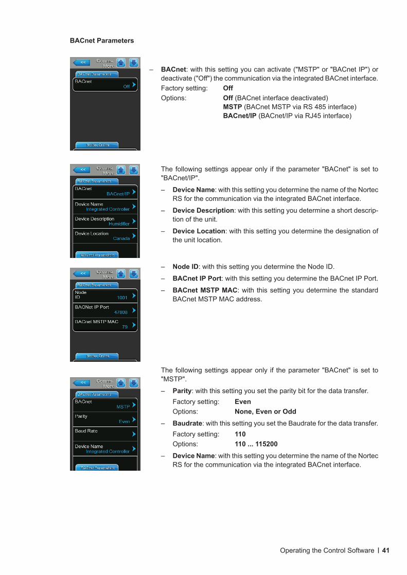
– BACnet: with this setting you can activate ("MSTP" or "BACnet IP") or deactivate ("Off") the communication via the integrated BACnet interface.Factory setting: OffOptions: Off (BACnet interface deactivated)
MSTP (BACnet MSTP via RS 485 interface) BACnet/IP (BACnet/IP via RJ45 interface)
The following settings appear only if the parameter "BACnet" is set to "BACnet/IP".
– Device Name: with this setting you determine the name of the Nortec RS for the communication via the integrated BACnet interface.
– Device Description: with this setting you determine a short descrip-tion of the unit.
– Device Location: with this setting you determine the designation of the unit location.
– Node ID: with this setting you determine the Node ID.
– BACnet IP Port: with this setting you determine the BACnet IP Port.
– BACnet MSTP MAC: with this setting you determine the standard BACnet MSTP MAC address.
The following settings appear only if the parameter "BACnet" is set to "MSTP".
– Parity: with this setting you set the parity bit for the data transfer.Factory setting: EvenOptions: None, Even or Odd
– Baudrate: with this setting you set the Baudrate for the data transfer.Factory setting: 110Options: 110 ... 115200
– Device Name: with this setting you determine the name of the Nortec RS for the communication via the integrated BACnet interface.
BACnet Parameters
42 Operating the Control Software
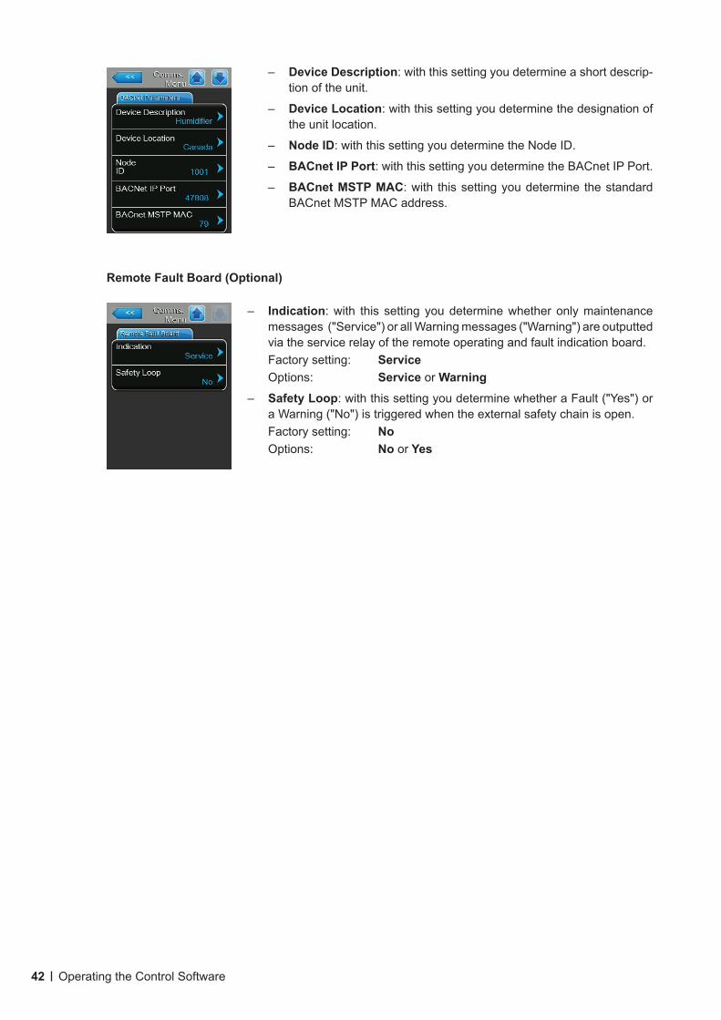
– Device Description: with this setting you determine a short descrip-tion of the unit.
– Device Location: with this setting you determine the designation of the unit location.
– Node ID: with this setting you determine the Node ID.
– BACnet IP Port: with this setting you determine the BACnet IP Port.
– BACnet MSTP MAC: with this setting you determine the standard BACnet MSTP MAC address.
Remote Fault Board (Optional)
– Indication: with this setting you determine whether only maintenance messages ("Service") or all Warning messages ("Warning") are outputted via the service relay of the remote operating and fault indication board.Factory setting: ServiceOptions: Service or Warning
– Safety Loop: with this setting you determine whether a Fault ("Yes") or a Warning ("No") is triggered when the external safety chain is open.Factory setting: NoOptions: No or Yes
43Operating the Control Software
Password: 0335
5.5 Maintenance Functions
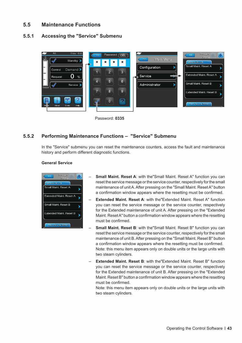
5.5.1 Accessing the "Service" Submenu
5.5.2 PerformingMaintenanceFunctions–"Service"Submenu
In the "Service" submenu you can reset the maintenance counters, access the fault and maintenance history and perform different diagnostic functions.
General Service
– Small Maint. Reset A: with the"Small Maint. Reset A" function you can reset the service message or the service counter, respectively for the small maintenance of unit A. After pressing on the "Small Maint. Reset A" button a confirmation window appears where the resetting must be confirmed.
– Extended Maint. Reset A: with the"Extended Maint. Reset A" function you can reset the service message or the service counter, respectively for the Extended maintenance of unit A. After pressing on the "Extended Maint. Reset A" button a confirmation window appears where the resetting must be confirmed.
– Small Maint. Reset B: with the"Small Maint. Reset B" function you can reset the service message or the service counter, respectively for the small maintenance of unit B. After pressing on the "Small Maint. Reset B" button a confirmation window appears where the resetting must be confirmed.Note: this menu item appears only on double units or the large units with two steam cylinders.
– Extended Maint. Reset B: with the"Extended Maint. Reset B" function you can reset the service message or the service counter, respectively for the Extended maintenance of unit B. After pressing on the "Extended Maint. Reset B" button a confirmation window appears where the resetting must be confirmed.Note: this menu item appears only on double units or the large units with two steam cylinders.
44 Operating the Control Software
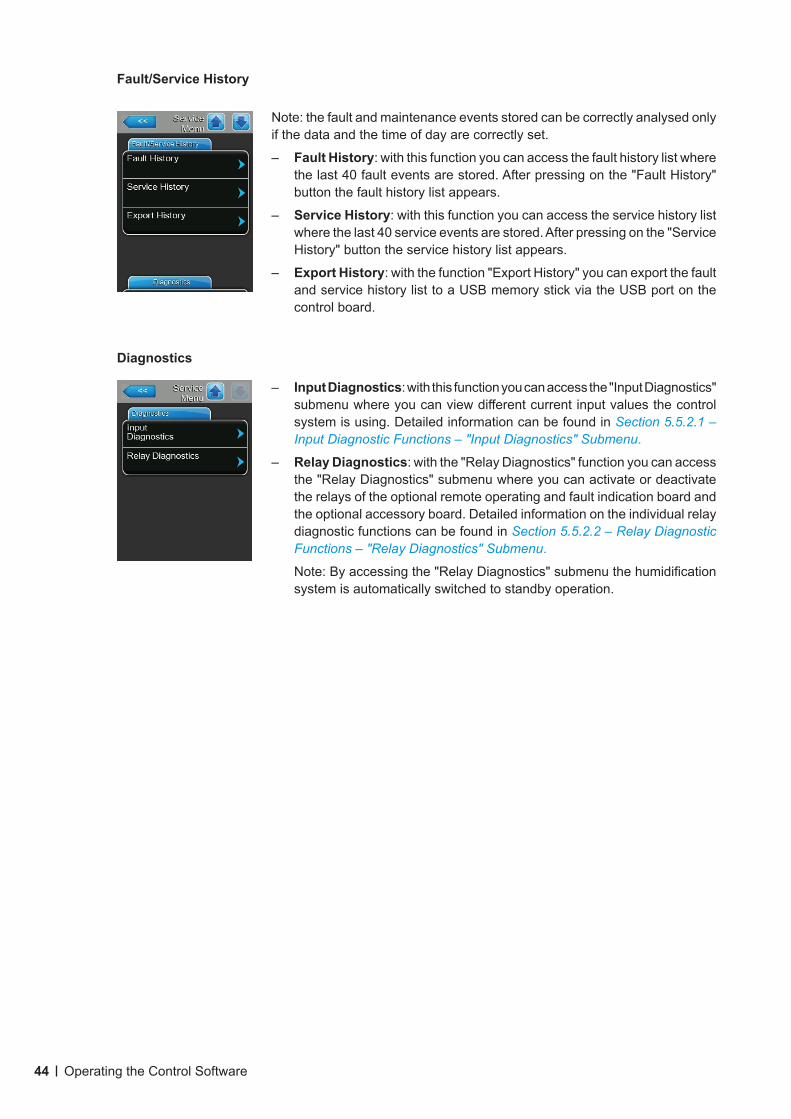
Fault/Service History
Note: the fault and maintenance events stored can be correctly analysed only if the data and the time of day are correctly set.
– Fault History: with this function you can access the fault history list where the last 40 fault events are stored. After pressing on the "Fault History" button the fault history list appears.
– Service History: with this function you can access the service history list where the last 40 service events are stored. After pressing on the "Service History" button the service history list appears.
– Export History: with the function "Export History" you can export the fault and service history list to a USB memory stick via the USB port on the control board.
Diagnostics
– Input Diagnostics: with this function you can access the "Input Diagnostics" submenu where you can view different current input values the control system is using. Detailed information can be found in Section 5.5.2.1 – Input Diagnostic Functions – "Input Diagnostics" Submenu.
– Relay Diagnostics: with the "Relay Diagnostics" function you can access the "Relay Diagnostics" submenu where you can activate or deactivate the relays of the optional remote operating and fault indication board and the optional accessory board. Detailed information on the individual relay diagnostic functions can be found in Section 5.5.2.2 – Relay Diagnostic Functions – "Relay Diagnostics" Submenu.
Note: By accessing the "Relay Diagnostics" submenu the humidification system is automatically switched to standby operation.
45Operating the Control Software
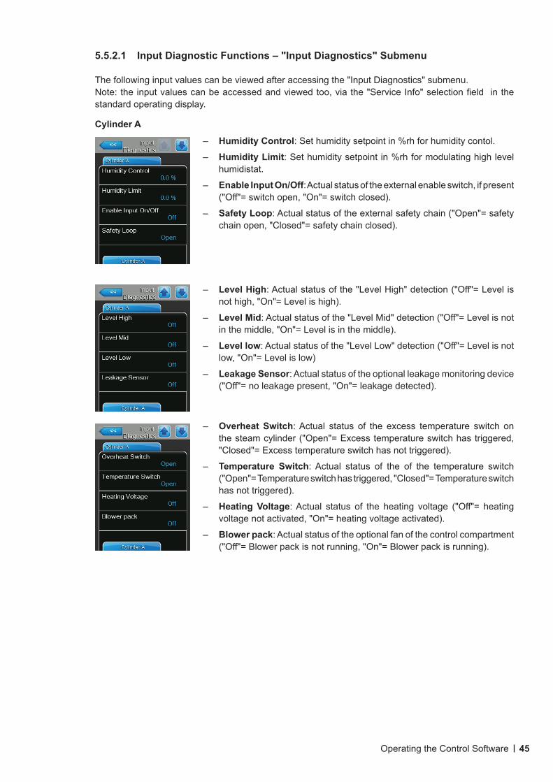
5.5.2.1 InputDiagnosticFunctions–"InputDiagnostics"Submenu
The following input values can be viewed after accessing the "Input Diagnostics" submenu.Note: the input values can be accessed and viewed too, via the "Service Info" selection field in the standard operating display.
Cylinder A
– Humidity Control: Set humidity setpoint in %rh for humidity contol.
– Humidity Limit: Set humidity setpoint in %rh for modulating high level humidistat.
– Enable Input On/Off: Actual status of the external enable switch, if present ("Off"= switch open, "On"= switch closed).
– Safety Loop: Actual status of the external safety chain ("Open"= safety chain open, "Closed"= safety chain closed).
– Level High: Actual status of the "Level High" detection ("Off"= Level is not high, "On"= Level is high).
– Level Mid: Actual status of the "Level Mid" detection ("Off"= Level is not in the middle, "On"= Level is in the middle).
– Level low: Actual status of the "Level Low" detection ("Off"= Level is not low, "On"= Level is low)
– Leakage Sensor: Actual status of the optional leakage monitoring device ("Off"= no leakage present, "On"= leakage detected).
– Overheat Switch: Actual status of the excess temperature switch on the steam cylinder ("Open"= Excess temperature switch has triggered, "Closed"= Excess temperature switch has not triggered).
– Temperature Switch: Actual status of the of the temperature switch ("Open"= Temperature switch has triggered, "Closed"= Temperature switch has not triggered).
– Heating Voltage: Actual status of the heating voltage ("Off"= heating voltage not activated, "On"= heating voltage activated).
– Blower pack: Actual status of the optional fan of the control compartment ("Off"= Blower pack is not running, "On"= Blower pack is running).
46 Operating the Control Software
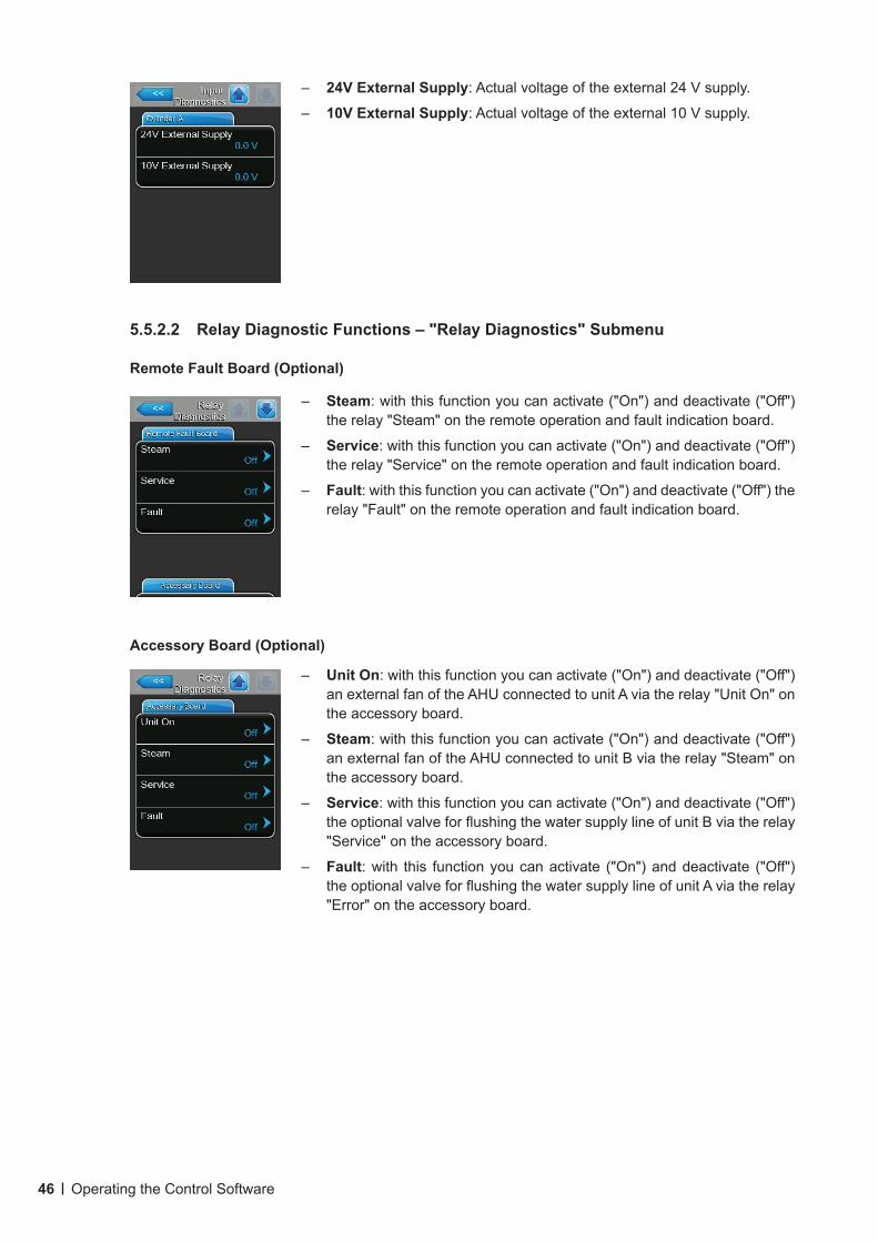
– 24V External Supply: Actual voltage of the external 24 V supply.
– 10V External Supply: Actual voltage of the external 10 V supply.
5.5.2.2 RelayDiagnosticFunctions–"RelayDiagnostics"Submenu
Remote Fault Board (Optional)
– Steam: with this function you can activate ("On") and deactivate ("Off") the relay "Steam" on the remote operation and fault indication board.
– Service: with this function you can activate ("On") and deactivate ("Off") the relay "Service" on the remote operation and fault indication board.
– Fault: with this function you can activate ("On") and deactivate ("Off") the relay "Fault" on the remote operation and fault indication board.
Accessory Board (Optional)
– Unit On: with this function you can activate ("On") and deactivate ("Off") an external fan of the AHU connected to unit A via the relay "Unit On" on the accessory board.
– Steam: with this function you can activate ("On") and deactivate ("Off") an external fan of the AHU connected to unit B via the relay "Steam" on the accessory board.
– Service: with this function you can activate ("On") and deactivate ("Off") the optional valve for flushing the water supply line of unit B via the relay "Service" on the accessory board.
– Fault: with this function you can activate ("On") and deactivate ("Off") the optional valve for flushing the water supply line of unit A via the relay "Error" on the accessory board.
47Operating the Control Software
Password: 0335
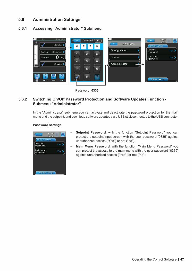
5.6 Administration Settings
5.6.1 Accessing "Administrator" Submenu
5.6.2 Switching On/Off Password Protection and Software Updates Function - Submenu "Administrator"
In the "Administrator" submenu you can activate and deactivate the password protection for the main menu and the setpoint, and download software updates via a USB stick connected to the USB connector.
Password settings
– Setpoint Password: with the function "Setpoint Password" you can protect the setpoint input screen with the user password "0335" against unauthorized access ("Yes") or not ("no").
– Main Menu Password: with the function "Main Menu Password" you can protect the access to the main menu with the user password "0335" against unauthorized access ("Yes") or not ("no")
48 Operating the Control Software
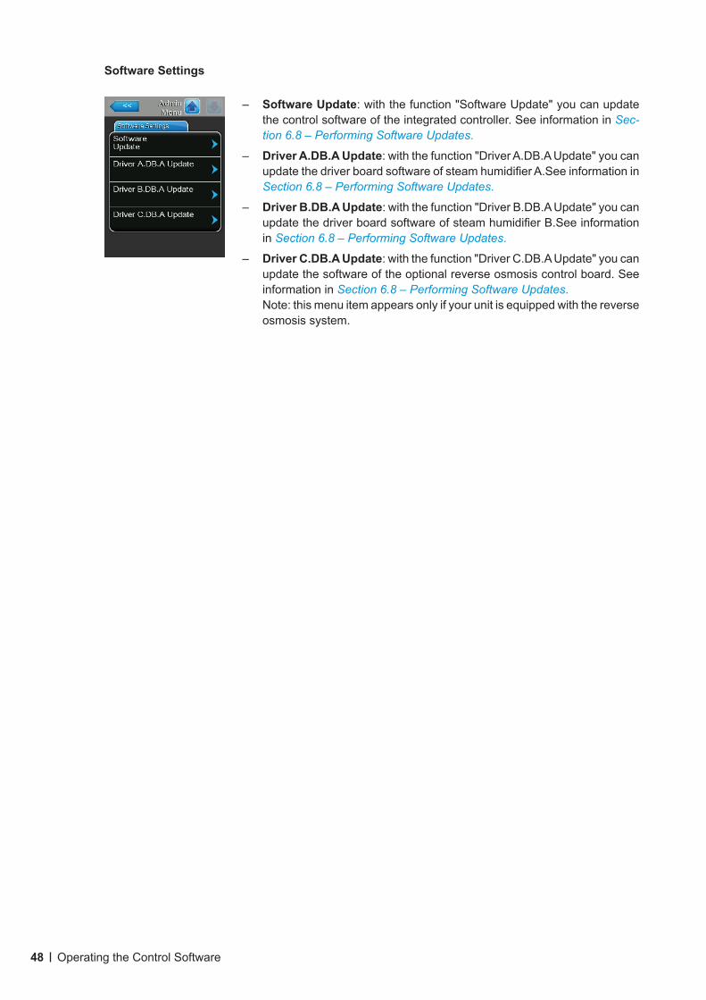
– Software Update: with the function "Software Update" you can update the control software of the integrated controller. See information in Sec-tion 6.8 – Performing Software Updates.
– Driver A.DB.A Update: with the function "Driver A.DB.A Update" you can update the driver board software of steam humidifier A.See information in Section 6.8 – Performing Software Updates.
– Driver B.DB.A Update: with the function "Driver B.DB.A Update" you can update the driver board software of steam humidifier B.See information in Section 6.8 – Performing Software Updates.
– Driver C.DB.A Update: with the function "Driver C.DB.A Update" you can update the software of the optional reverse osmosis control board. See information in Section 6.8 – Performing Software Updates.Note: this menu item appears only if your unit is equipped with the reverse osmosis system.
Software Settings
49Maintenance
6 Maintenance
6.1 Important Notes on Maintenance
QualificationofpersonnelAll maintenance work must be carried out only by wellqualifiedandtrainedpersonnelauthorisedbythe owner. It is the owner’s responsibility to verify proper qualification of the personnel.
General note The instructions and details for maintenance work must be followed and upheld.
Only the maintenance work described in this documentation may be carried out.
Only use original Nortec spare parts to replace faulty parts.
SafetySome maintenance work requires removal of the unit covers. Please note the following:
DANGER!Dangerofelectrichazard!
You may get in touch with live parts when the unit is open. Touching live parts may cause severe injury or even death.
Prevention: Before carrying out any maintenance work set the Nortec RS out of operation as described in Section 4.5 – Taking the Unit Out of Operation (switch off the unit, disconnect it from the mains and stop the water supply) and secure the unit against inadvertent power-up.
CAUTION!
The electronic components inside the humidifier are very sensitive to electrostatic discharge.
Prevention: Before carrying out any maintenance work to the electrical or electronic equipment of the humidifier, appropriate measures must be taken to protect the respective components against damage caused by electrostatic discharge (ESD protection).
WARNING! Danger of burning!
The water in the steam cylinder and in the scale collector tank can be hot, up to 203 °F (95 °C). There is danger of burning when the steam cylinder(s) and the scale collector tank(s) is/are dismounted shortly after steam has been produced. Prevention: Before carrying out any work on the steam system set the Nortec RS out of operation as described in Section 4.5 – Taking the Unit Out of Operation , then wait until the components have cooled down sufficiently (see temperature indication adhesive on the scale collector tank) thus pre-venting danger of burning.
50 Maintenance
6.2 Maintenance Intervals
To maintain operational safety the Nortec RS steam humidifier must be maintained at regular intervals. The control software of the Nortec RS features two maintenance counters one for the "Small mainte-nance" (Cleaning of the scale collector tank, only for units equipped with a scale collector tank) and one for the "Extended maintenance" (Cleaning of the steam cylinder and othe components of the steam and water system). The maintenance counters are set at the initial commissioning based on the water condition on site, however the maintenance counters can be adjusted at any time later to the actual operational conditions.
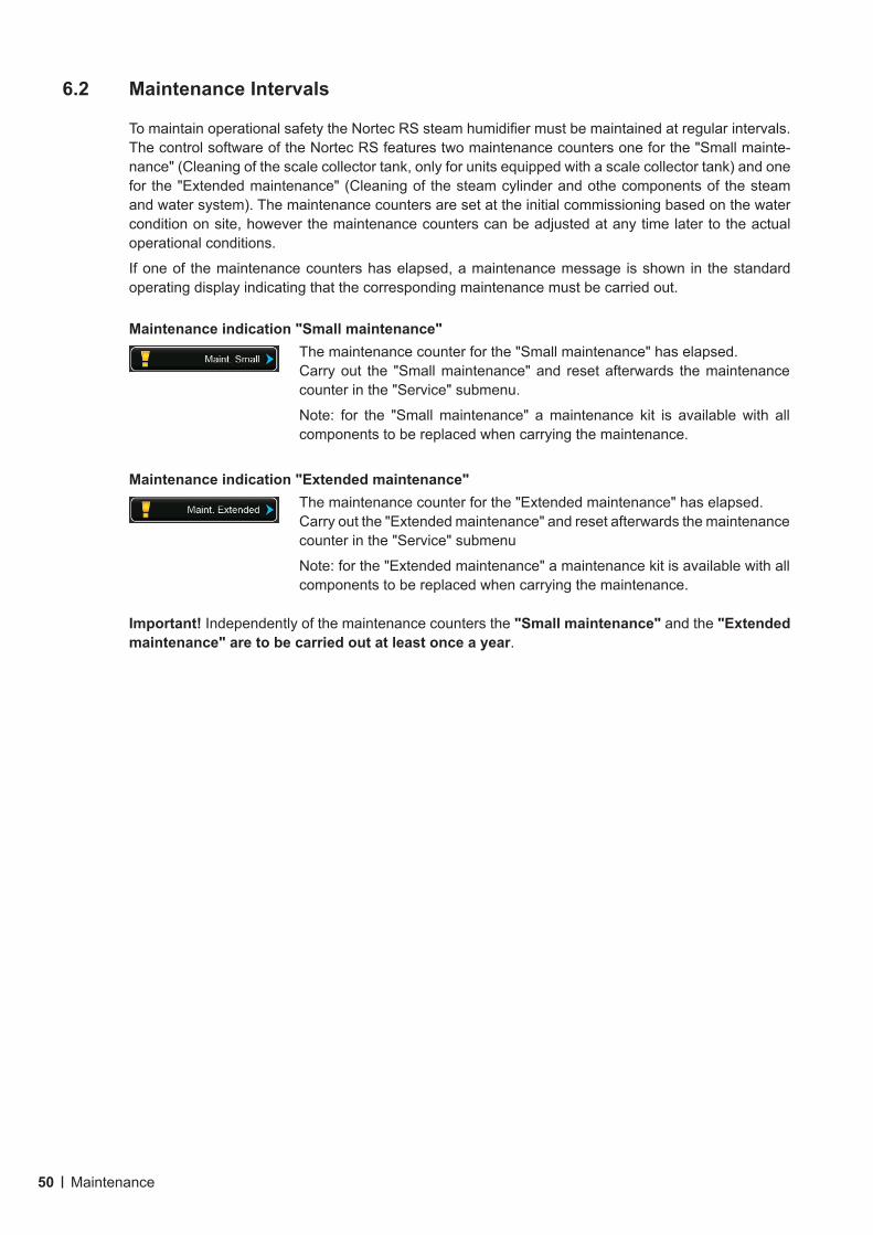
If one of the maintenance counters has elapsed, a maintenance message is shown in the standard operating display indicating that the corresponding maintenance must be carried out.
Maintenance indication "Small maintenance"The maintenance counter for the "Small maintenance" has elapsed.Carry out the "Small maintenance" and reset afterwards the maintenance counter in the "Service" submenu.
Note: for the "Small maintenance" a maintenance kit is available with all components to be replaced when carrying the maintenance.
Maintenance indication "Extended maintenance"The maintenance counter for the "Extended maintenance" has elapsed.Carry out the "Extended maintenance" and reset afterwards the maintenance counter in the "Service" submenu
Note: for the "Extended maintenance" a maintenance kit is available with all components to be replaced when carrying the maintenance.
Important! Independently of the maintenance counters the "Small maintenance" and the "Extended maintenance" are to be carried out at least once a year.
51Maintenance
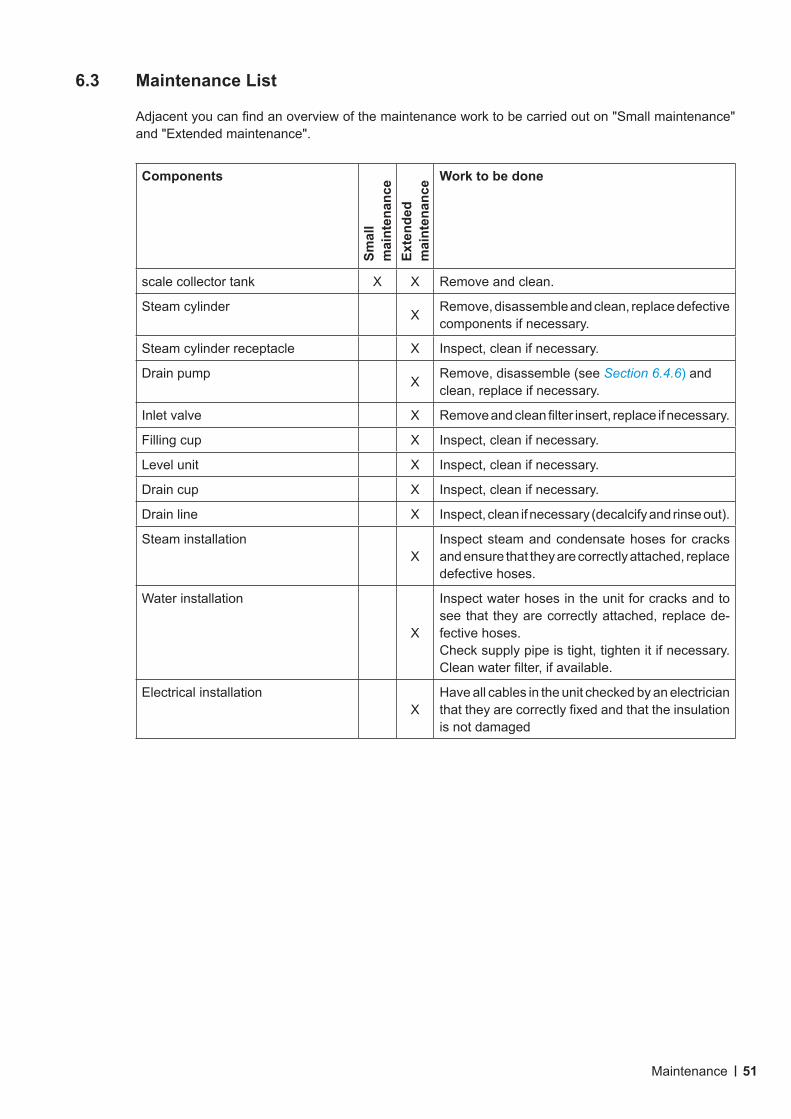
6.3 Maintenance List
Adjacent you can find an overview of the maintenance work to be carried out on "Small maintenance" and "Extended maintenance".
Components
Smal
l m
aint
enan
ceEx
tend
ed
mai
nten
ance
Work to be done
scale collector tank X X Remove and clean.
Steam cylinder X Remove, disassemble and clean, replace defective components if necessary.
Steam cylinder receptacle X Inspect, clean if necessary.
Drain pump X Remove, disassemble (see Section 6.4.6) and clean, replace if necessary.
Inlet valve X Remove and clean filter insert, replace if necessary.
Filling cup X Inspect, clean if necessary.
Level unit X Inspect, clean if necessary.
Drain cup X Inspect, clean if necessary.
Drain line X Inspect, clean if necessary (decalcify and rinse out).
Steam installationX
Inspect steam and condensate hoses for cracks and ensure that they are correctly attached, replace defective hoses.
Water installation
X
Inspect water hoses in the unit for cracks and to see that they are correctly attached, replace de-fective hoses.Check supply pipe is tight, tighten it if necessary. Clean water filter, if available.
Electrical installationX
Have all cables in the unit checked by an electrician that they are correctly fixed and that the insulation is not damaged
52 Maintenance
6.4 Removing and Installing Components for Maintenance
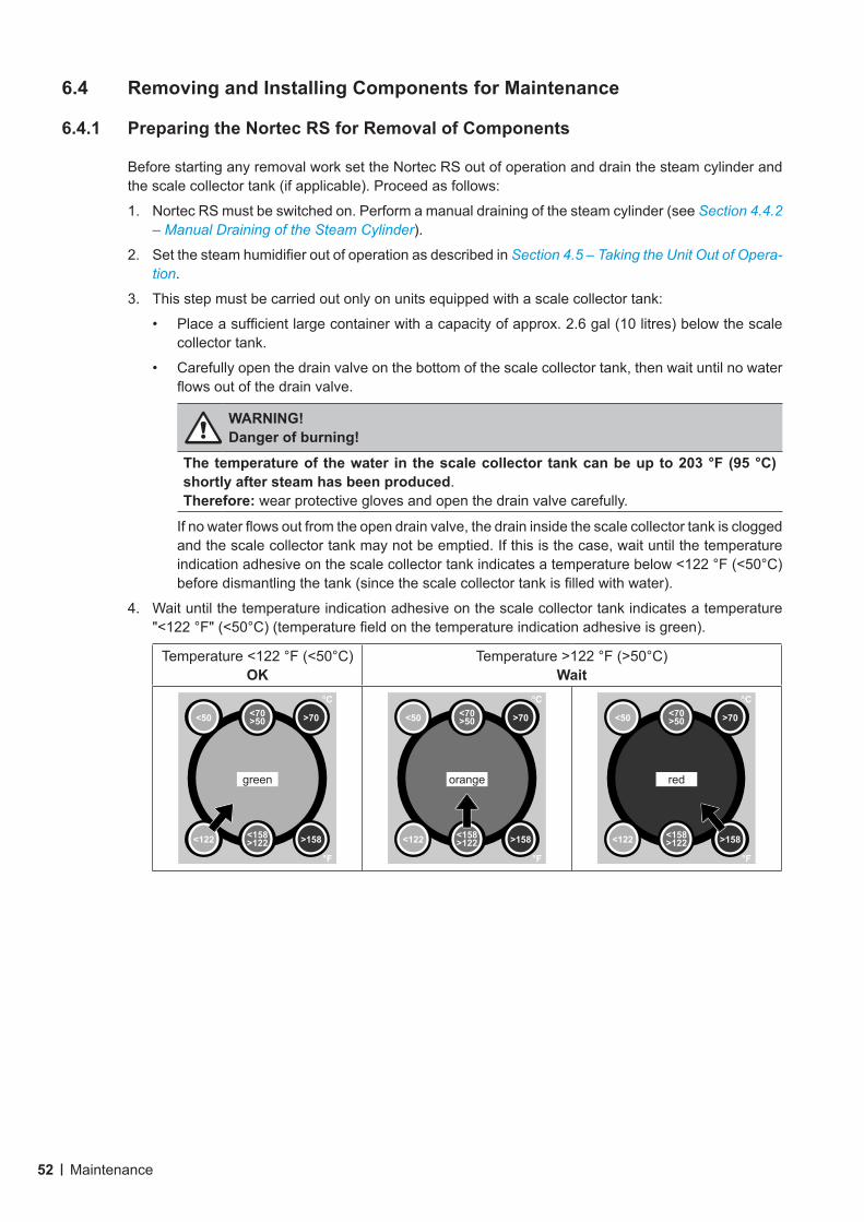
6.4.1 Preparing the Nortec RS for Removal of Components
Before starting any removal work set the Nortec RS out of operation and drain the steam cylinder and the scale collector tank (if applicable). Proceed as follows:
1. Nortec RS must be switched on. Perform a manual draining of the steam cylinder (see Section 4.4.2 – Manual Draining of the Steam Cylinder).
2. Set the steam humidifier out of operation as described in Section 4.5 – Taking the Unit Out of Opera-tion.
3. This step must be carried out only on units equipped with a scale collector tank:
• Place a sufficient large container with a capacity of approx. 2.6 gal (10 litres) below the scale collector tank.
• Carefully open the drain valve on the bottom of the scale collector tank, then wait until no water flows out of the drain valve.
WARNING! Danger of burning!
The temperature of the water in the scale collector tank can be up to 203 °F (95 °C) shortly after steam has been produced. Therefore: wear protective gloves and open the drain valve carefully.
If no water flows out from the open drain valve, the drain inside the scale collector tank is clogged and the scale collector tank may not be emptied. If this is the case, wait until the temperature indication adhesive on the scale collector tank indicates a temperature below <122 °F (<50°C) before dismantling the tank (since the scale collector tank is filled with water).
4. Wait until the temperature indication adhesive on the scale collector tank indicates a temperature "<122 °F" (<50°C) (temperature field on the temperature indication adhesive is green).
Temperature <122 °F (<50°C) OK
Temperature >122 °F (>50°C) Wait
°C
°F
>158<122 <158>122
>70<50 <70>50
green
°C
°F
>158<122 <158>122
>70<50 <70>50
orange
°C
°F
>158<122 <158>122
>70<50 <70>50
red
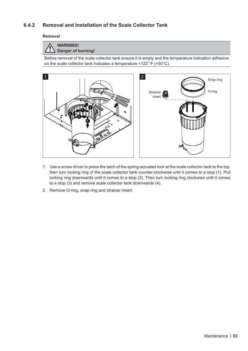
53Maintenance
6.4.2 Removal and Installation of the Scale Collector Tank
Removal
WARNING! Danger of burning!
Before removal of the scale collector tank ensure it is empty and the temperature indication adhesive on the scale collector tank indicates a temperature <122 °F (<50°C).
1. Use a screw driver to press the latch of the spring-actuated lock at the scale collector tank to the top, then turn locking ring of the scale collector tank counter-clockwise until it comes to a stop (1). Pull locking ring downwards until it comes to a stop (2). Then turn locking ring clockwise until it comes to a stop (3) and remove scale collector tank downwards (4).
2. Remove O-ring, snap ring and strainer insert.
1
1.1.
3.4.
2.
2
Strainer insert
Snap ring
O-ring
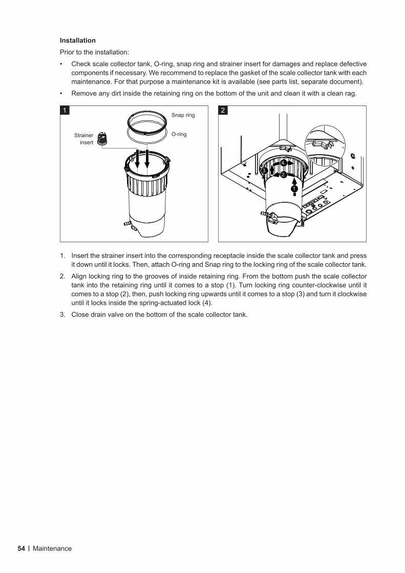
54 Maintenance
InstallationPrior to the installation:
• Check scale collector tank, O-ring, snap ring and strainer insert for damages and replace defective components if necessary. We recommend to replace the gasket of the scale collector tank with each maintenance. For that purpose a maintenance kit is available (see parts list, separate document).
• Remove any dirt inside the retaining ring on the bottom of the unit and clean it with a clean rag.
1. Insert the strainer insert into the corresponding receptacle inside the scale collector tank and press it down until it locks. Then, attach O-ring and Snap ring to the locking ring of the scale collector tank.
2. Align locking ring to the grooves of inside retaining ring. From the bottom push the scale collector tank into the retaining ring until it comes to a stop (1). Turn locking ring counter-clockwise until it comes to a stop (2), then, push locking ring upwards until it comes to a stop (3) and turn it clockwise until it locks inside the spring-actuated lock (4).
3. Close drain valve on the bottom of the scale collector tank.
2
4.
2.
1.
3.
1
Strainer insert
Snap ring
O-ring
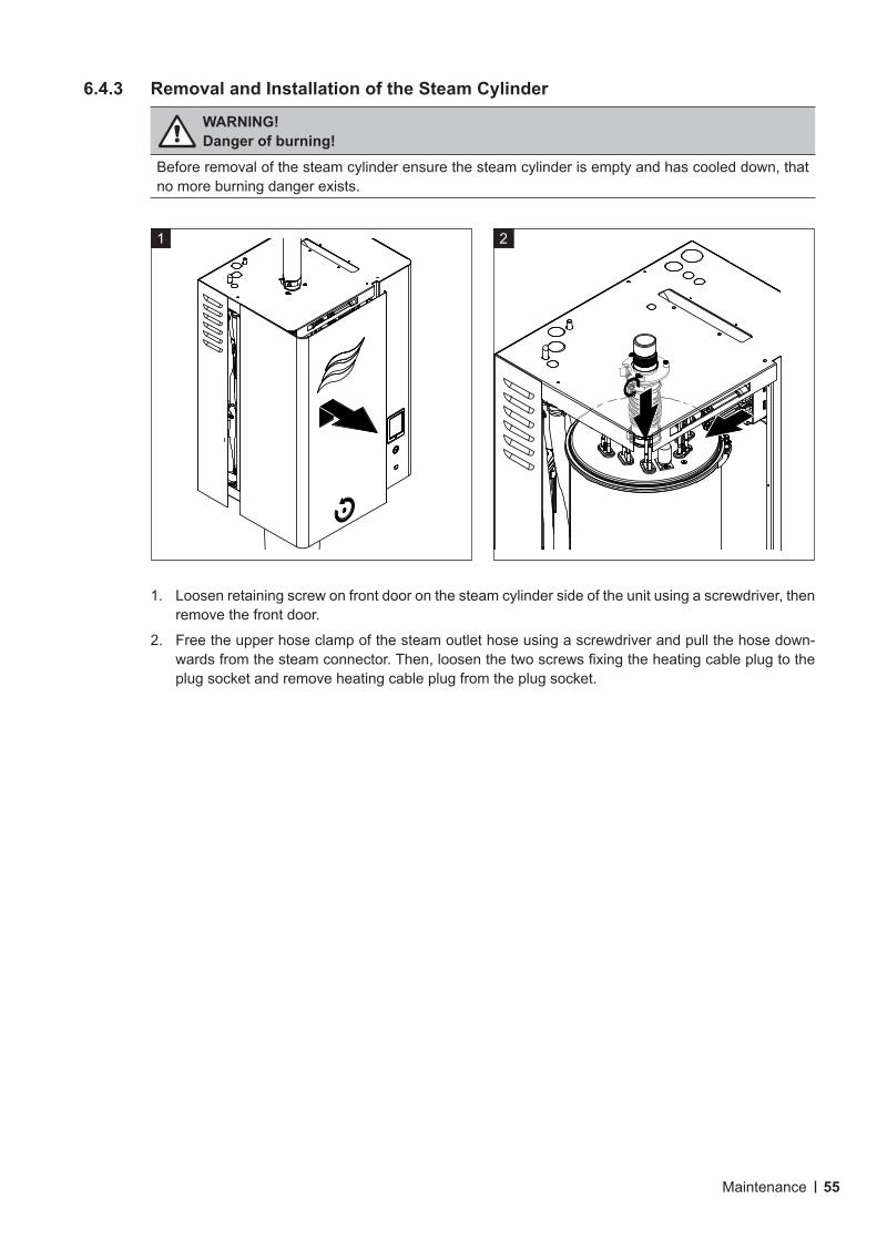
55Maintenance
6.4.3 Removal and Installation of the Steam Cylinder
WARNING! Danger of burning!
Before removal of the steam cylinder ensure the steam cylinder is empty and has cooled down, that no more burning danger exists.
1. Loosen retaining screw on front door on the steam cylinder side of the unit using a screwdriver, then remove the front door.
2. Free the upper hose clamp of the steam outlet hose using a screwdriver and pull the hose down-wards from the steam connector. Then, loosen the two screws fixing the heating cable plug to the plug socket and remove heating cable plug from the plug socket.
21
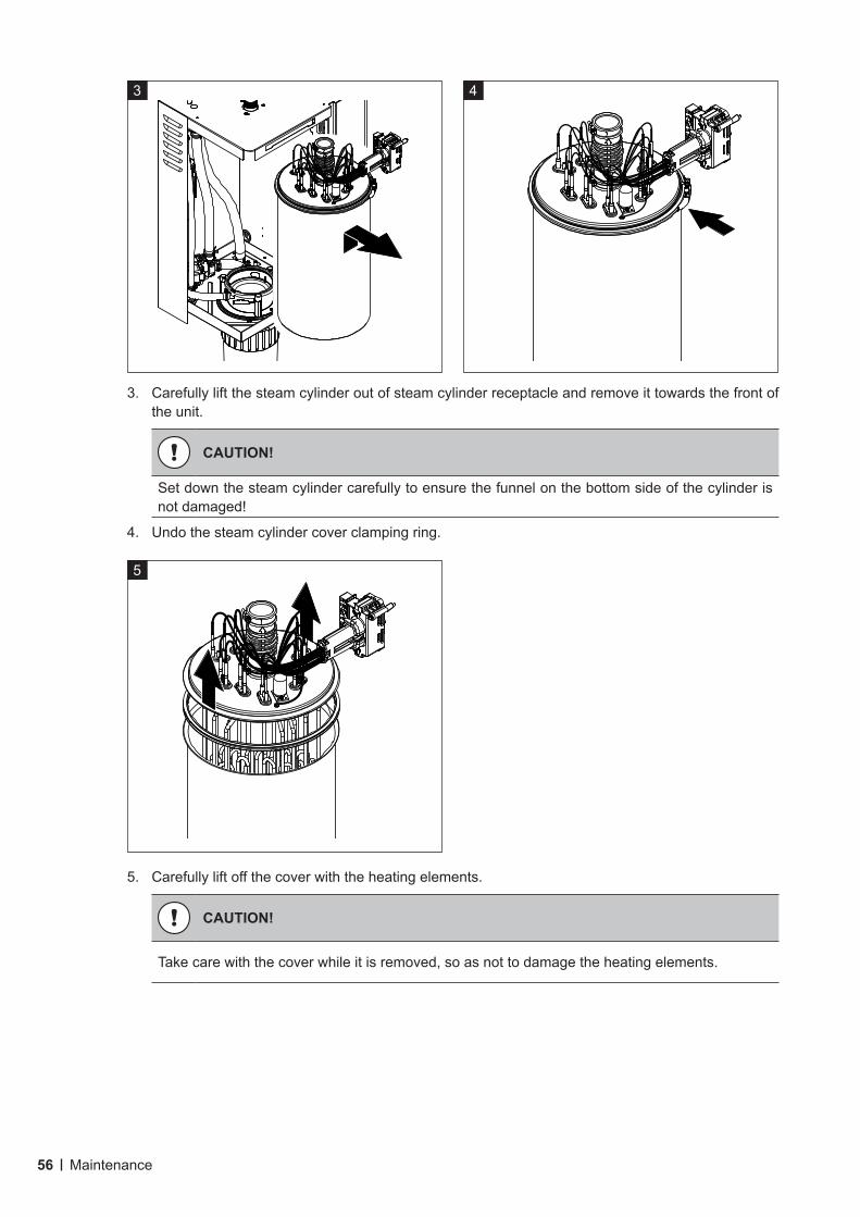
56 Maintenance
3. Carefully lift the steam cylinder out of steam cylinder receptacle and remove it towards the front of the unit.
CAUTION!
Set down the steam cylinder carefully to ensure the funnel on the bottom side of the cylinder is not damaged!
4. Undo the steam cylinder cover clamping ring.
5. Carefully lift off the cover with the heating elements.
CAUTION!
Take care with the cover while it is removed, so as not to damage the heating elements.
5
4 3
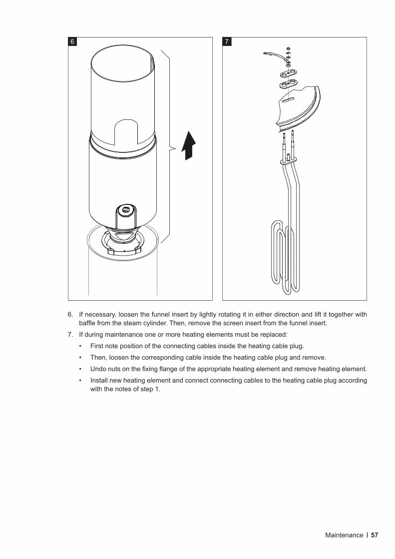
57Maintenance
7 6
6. If necessary, loosen the funnel insert by lightly rotating it in either direction and lift it together with baffle from the steam cylinder. Then, remove the screen insert from the funnel insert.
7. If during maintenance one or more heating elements must be replaced:
• First note position of the connecting cables inside the heating cable plug.
• Then, loosen the corresponding cable inside the heating cable plug and remove.
• Undo nuts on the fixing flange of the appropriate heating element and remove heating element.
• Install new heating element and connect connecting cables to the heating cable plug according with the notes of step 1.
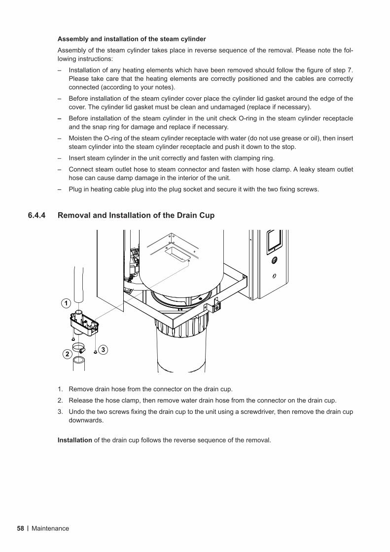
58 Maintenance
Assembly and installation of the steam cylinderAssembly of the steam cylinder takes place in reverse sequence of the removal. Please note the fol-lowing instructions:
– Installation of any heating elements which have been removed should follow the figure of step 7. Please take care that the heating elements are correctly positioned and the cables are correctly connected (according to your notes).
– Before installation of the steam cylinder cover place the cylinder lid gasket around the edge of the cover. The cylinder lid gasket must be clean and undamaged (replace if necessary).
– Before installation of the steam cylinder in the unit check O-ring in the steam cylinder receptacle and the snap ring for damage and replace if necessary.
– Moisten the O-ring of the steam cylinder receptacle with water (do not use grease or oil), then insert steam cylinder into the steam cylinder receptacle and push it down to the stop.
– Insert steam cylinder in the unit correctly and fasten with clamping ring.
– Connect steam outlet hose to steam connector and fasten with hose clamp. A leaky steam outlet hose can cause damp damage in the interior of the unit.
– Plug in heating cable plug into the plug socket and secure it with the two fixing screws.
6.4.4 Removal and Installation of the Drain Cup
1. Remove drain hose from the connector on the drain cup.
2. Release the hose clamp, then remove water drain hose from the connector on the drain cup.
3. Undo the two screws fixing the drain cup to the unit using a screwdriver, then remove the drain cup downwards.
Installation of the drain cup follows the reverse sequence of the removal.
1
2 3
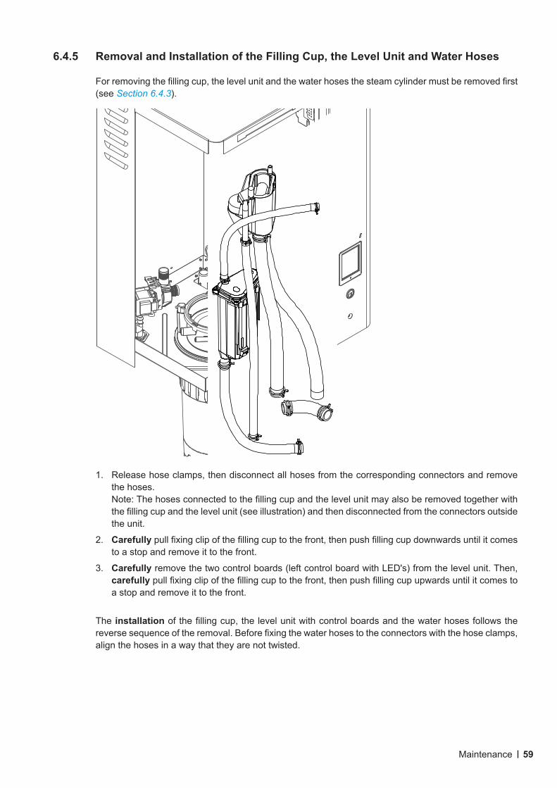
59Maintenance
6.4.5 Removal and Installation of the Filling Cup, the Level Unit and Water Hoses
For removing the filling cup, the level unit and the water hoses the steam cylinder must be removed first (see Section 6.4.3).
1. Release hose clamps, then disconnect all hoses from the corresponding connectors and remove the hoses.Note: The hoses connected to the filling cup and the level unit may also be removed together with the filling cup and the level unit (see illustration) and then disconnected from the connectors outside the unit.
2. Carefully pull fixing clip of the filling cup to the front, then push filling cup downwards until it comes to a stop and remove it to the front.
3. Carefully remove the two control boards (left control board with LED's) from the level unit. Then, carefully pull fixing clip of the filling cup to the front, then push filling cup upwards until it comes to a stop and remove it to the front.
The installation of the filling cup, the level unit with control boards and the water hoses follows the reverse sequence of the removal. Before fixing the water hoses to the connectors with the hose clamps, align the hoses in a way that they are not twisted.
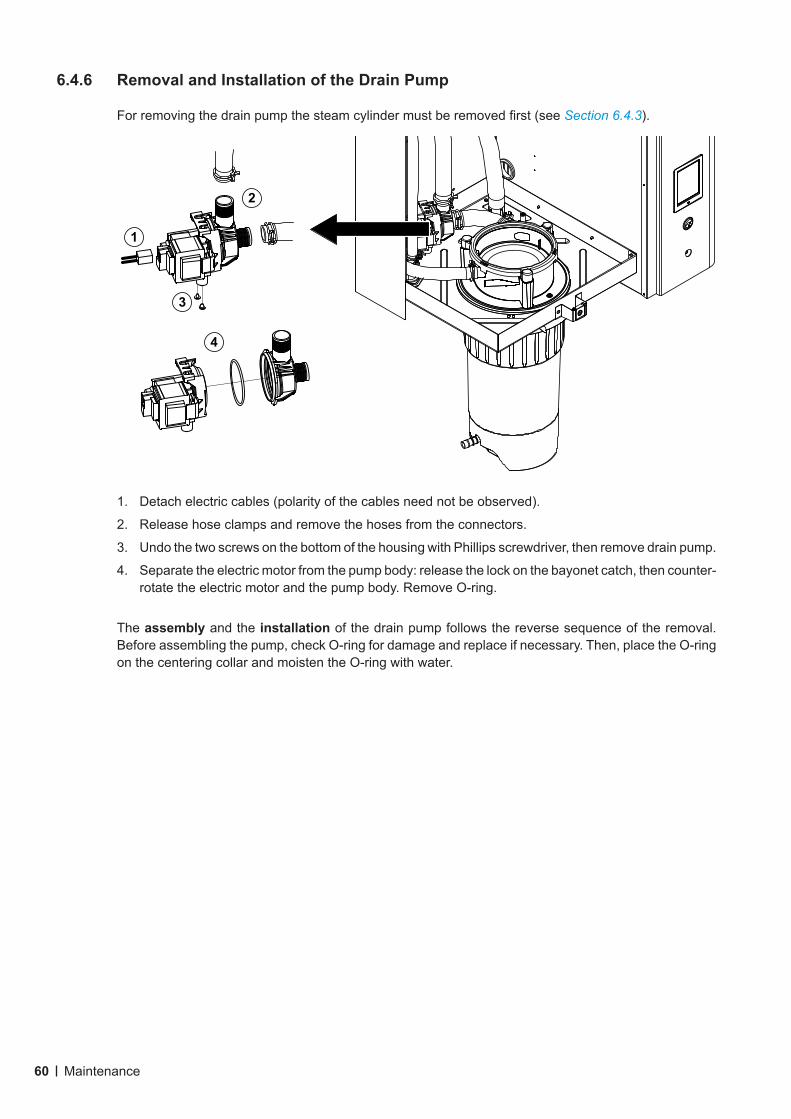
60 Maintenance
6.4.6 Removal and Installation of the Drain Pump
For removing the drain pump the steam cylinder must be removed first (see Section 6.4.3).
1. Detach electric cables (polarity of the cables need not be observed).
2. Release hose clamps and remove the hoses from the connectors.
3. Undo the two screws on the bottom of the housing with Phillips screwdriver, then remove drain pump.
4. Separate the electric motor from the pump body: release the lock on the bayonet catch, then counter-rotate the electric motor and the pump body. Remove O-ring.
The assembly and the installation of the drain pump follows the reverse sequence of the removal. Before assembling the pump, check O-ring for damage and replace if necessary. Then, place the O-ring on the centering collar and moisten the O-ring with water.
1
2
3
4
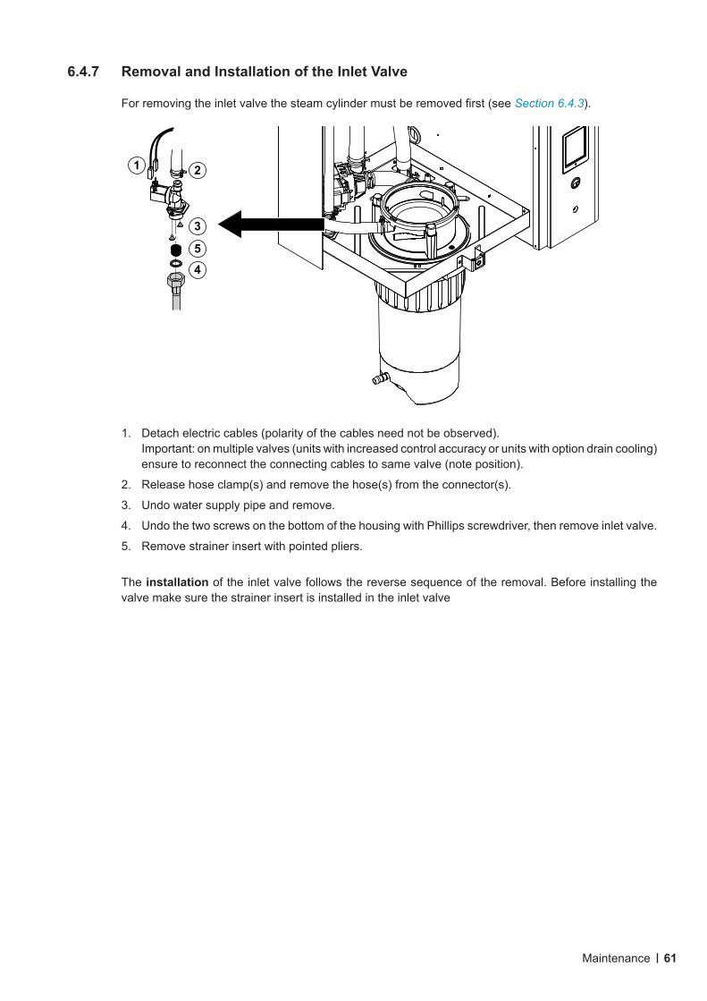
61Maintenance
6.4.7 Removal and Installation of the Inlet Valve
For removing the inlet valve the steam cylinder must be removed first (see Section 6.4.3).
1. Detach electric cables (polarity of the cables need not be observed). Important: on multiple valves (units with increased control accuracy or units with option drain cooling) ensure to reconnect the connecting cables to same valve (note position).
2. Release hose clamp(s) and remove the hose(s) from the connector(s).
3. Undo water supply pipe and remove.
4. Undo the two screws on the bottom of the housing with Phillips screwdriver, then remove inlet valve.
5. Remove strainer insert with pointed pliers.
The installation of the inlet valve follows the reverse sequence of the removal. Before installing the valve make sure the strainer insert is installed in the inlet valve
1 2
4
3
5
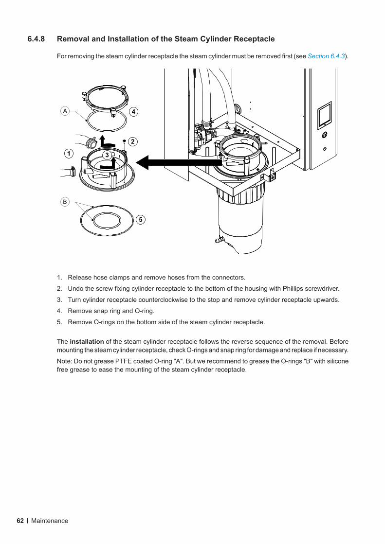
62 Maintenance
6.4.8 Removal and Installation of the Steam Cylinder Receptacle
For removing the steam cylinder receptacle the steam cylinder must be removed first (see Section 6.4.3).
1. Release hose clamps and remove hoses from the connectors.
2. Undo the screw fixing cylinder receptacle to the bottom of the housing with Phillips screwdriver.
3. Turn cylinder receptacle counterclockwise to the stop and remove cylinder receptacle upwards.
4. Remove snap ring and O-ring.
5. Remove O-rings on the bottom side of the steam cylinder receptacle.
The installation of the steam cylinder receptacle follows the reverse sequence of the removal. Before mounting the steam cylinder receptacle, check O-rings and snap ring for damage and replace if necessary.
Note: Do not grease PTFE coated O-ring "A". But we recommend to grease the O-rings "B" with silicone free grease to ease the mounting of the steam cylinder receptacle.
1
2
4
5
B
A
3
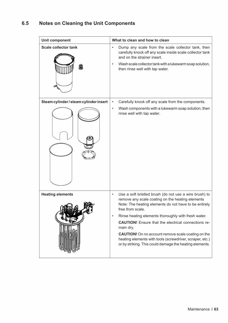
63Maintenance
6.5 Notes on Cleaning the Unit Components
Unit component What to clean and how to clean
Scale collector tank • Dump any scale from the scale collector tank, then carefully knock off any scale inside scale collector tank and on the strainer insert.
• Wash scale collector tank with a lukewarm soap solution, then rinse well with tap water.
Steam cylinder / steam cylinder insert • Carefully knock off any scale from the components.
• Wash components with a lukewarm soap solution, then rinse well with tap water.
Heating elements • Use a soft bristled brush (do not use a wire brush) to remove any scale coating on the heating elementsNote: The heating elements do not have to be entirely free from scale.
• Rinse heating elements thoroughly with fresh water.
CAUTION! Ensure that the electrical connections re-main dry.
CAUTION! On no account remove scale coating on the heating elements with tools (screwdriver, scraper, etc.) or by striking. This could damage the heating elements.
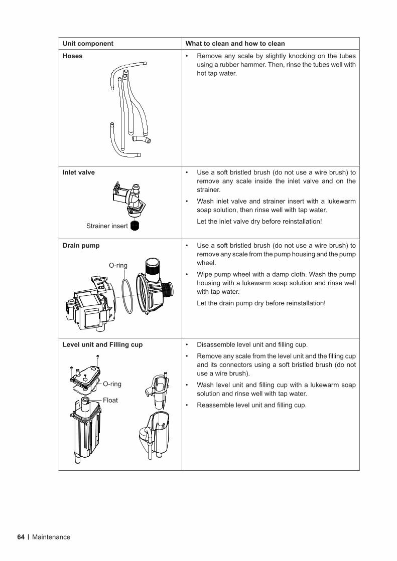
64 Maintenance
Unit component What to clean and how to clean
Hoses • Remove any scale by slightly knocking on the tubes using a rubber hammer. Then, rinse the tubes well with hot tap water.
Inlet valve • Use a soft bristled brush (do not use a wire brush) to remove any scale inside the inlet valve and on the strainer.
• Wash inlet valve and strainer insert with a lukewarm soap solution, then rinse well with tap water.
Let the inlet valve dry before reinstallation!
Drain pump • Use a soft bristled brush (do not use a wire brush) to remove any scale from the pump housing and the pump wheel.
• Wipe pump wheel with a damp cloth. Wash the pump housing with a lukewarm soap solution and rinse well with tap water.
Let the drain pump dry before reinstallation!
Level unit and Filling cup • Disassemble level unit and filling cup.
• Remove any scale from the level unit and the filling cup and its connectors using a soft bristled brush (do not use a wire brush).
• Wash level unit and filling cup with a lukewarm soap solution and rinse well with tap water.
• Reassemble level unit and filling cup.
O-ring
Strainer insert
O-ring
Float
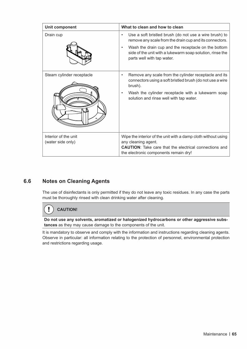
65Maintenance
Unit component What to clean and how to clean
Drain cup • Use a soft bristled brush (do not use a wire brush) to remove any scale from the drain cup and its connectors.
• Wash the drain cup and the receptacle on the bottom side of the unit with a lukewarm soap solution, rinse the parts well with tap water.
Steam cylinder receptacle • Remove any scale from the cylinder receptacle and its connectors using a soft bristled brush (do not use a wire brush).
• Wash the cylinder receptacle with a lukewarm soap solution and rinse well with tap water.
Interior of the unit (water side only)
Wipe the interior of the unit with a damp cloth without using any cleaning agent. CAUTION: Take care that the electrical connections and the electronic components remain dry!
6.6 Notes on Cleaning Agents
The use of disinfectants is only permitted if they do not leave any toxic residues. In any case the parts must be thoroughly rinsed with clean drinking water after cleaning.
CAUTION!
Donotuseanysolvents,aromatizedorhalogenizedhydrocarbonsorotheraggressivesubs-tances as they may cause damage to the components of the unit.
It is mandatory to observe and comply with the information and instructions regarding cleaning agents. Observe in particular: all information relating to the protection of personnel, environmental protection and restrictions regarding usage.
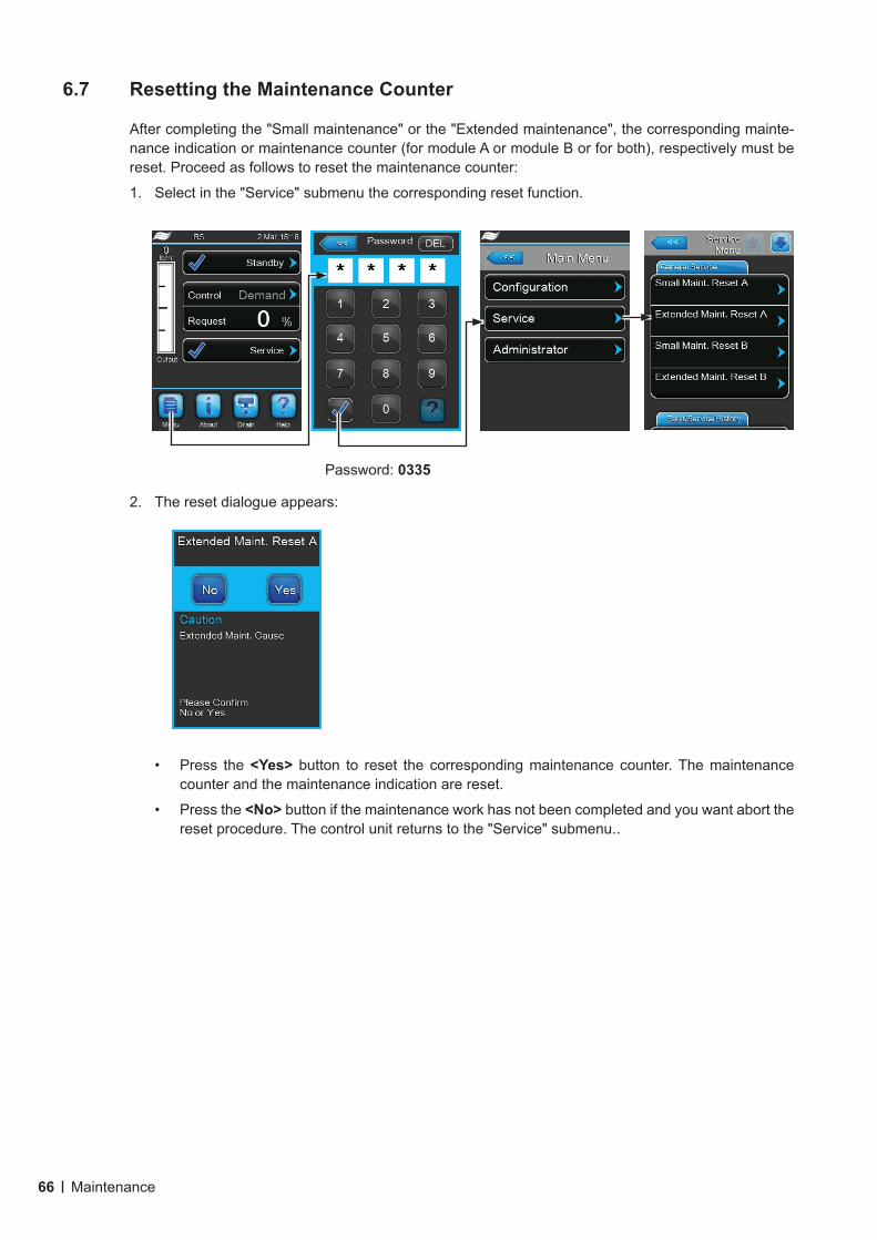
66 Maintenance
6.7 Resetting the Maintenance Counter
After completing the "Small maintenance" or the "Extended maintenance", the corresponding mainte-nance indication or maintenance counter (for module A or module B or for both), respectively must be reset. Proceed as follows to reset the maintenance counter:
1. Select in the "Service" submenu the corresponding reset function.
Password: 0335
2. The reset dialogue appears:
• Press the <Yes> button to reset the corresponding maintenance counter. The maintenance counter and the maintenance indication are reset.
• Press the <No> button if the maintenance work has not been completed and you want abort the reset procedure. The control unit returns to the "Service" submenu..
67Maintenance
6.8 Performing Software Updates
To perform a software update of the control software or of the driver boards, proceed as follows:
1. Switch off the voltage supply to the steam humidifier via the electrical isolator and secure switch in the off position to prevent it from inadvertent power up.
2. Unlock the front door on the electronic side of the steam humidifier and remove it.
3. Swivel control board assembly 90°outwards.
4. Connect USB memory stick (max. length 3 in/75 mm) containing the update software to the USB port of the control board.
5. Swivel control board assembly 90°inwards.
6. Close the front door of the steam humidifier and lock it with the screw.
7. Switch on power supply to the steam humidifier via the electrical isolator.
8. Access main menu and select in the "Administrator" submenu the desired software update function (e.g. "Control Software Update"). Then, follow the instructions in the display of the control unit.Note: in order to perform the update of the control software or of the driver board a USB stick with a valid software update (the update files must be on the highest level outside of any folder) must be connected to the USB port on the control board. Otherwise, an appropriate fault message appears when starting the software update.
9. During update a progress bar is shown in the display. If the update has completed the control unit returns to the standard operating display.
10. Repeat steps 1 to 6 to remove the USB memory stick.
11. To activated the new software the Nortec RS must be switched off and on again via the unit switch.
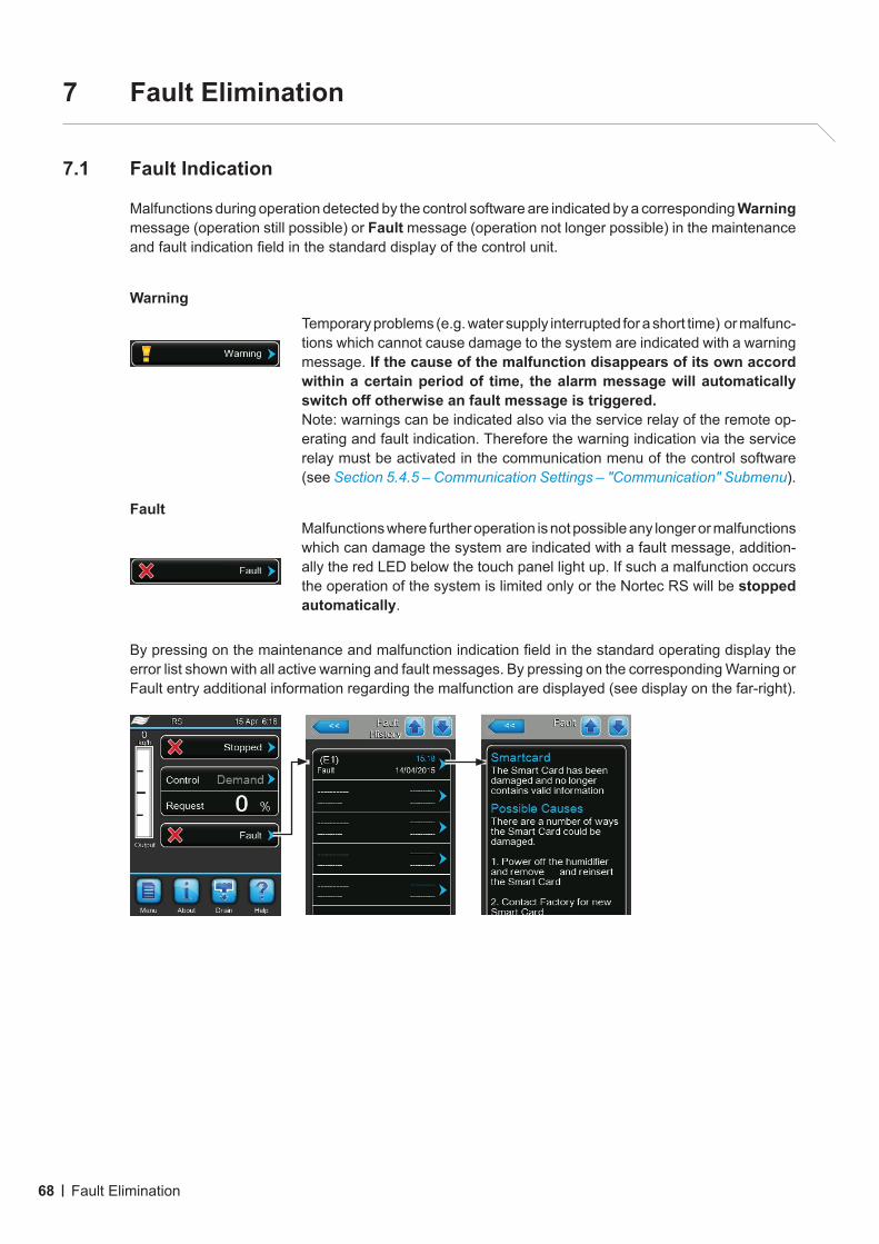
68 Fault Elimination
7 Fault Elimination
7.1 Fault Indication
Malfunctions during operation detected by the control software are indicated by a corresponding Warning message (operation still possible) or Fault message (operation not longer possible) in the maintenance and fault indication field in the standard display of the control unit.
WarningTemporary problems (e.g. water supply interrupted for a short time) or malfunc-tions which cannot cause damage to the system are indicated with a warning message. If the cause of the malfunction disappears of its own accord within a certain period of time, the alarm message will automatically switch off otherwise an fault message is triggered. Note: warnings can be indicated also via the service relay of the remote op-erating and fault indication. Therefore the warning indication via the service relay must be activated in the communication menu of the control software (see Section 5.4.5 – Communication Settings – "Communication" Submenu).
FaultMalfunctions where further operation is not possible any longer or malfunctions which can damage the system are indicated with a fault message, addition-ally the red LED below the touch panel light up. If such a malfunction occurs the operation of the system is limited only or the Nortec RS will be stopped automatically.
By pressing on the maintenance and malfunction indication field in the standard operating display the error list shown with all active warning and fault messages. By pressing on the corresponding Warning or Fault entry additional information regarding the malfunction are displayed (see display on the far-right).
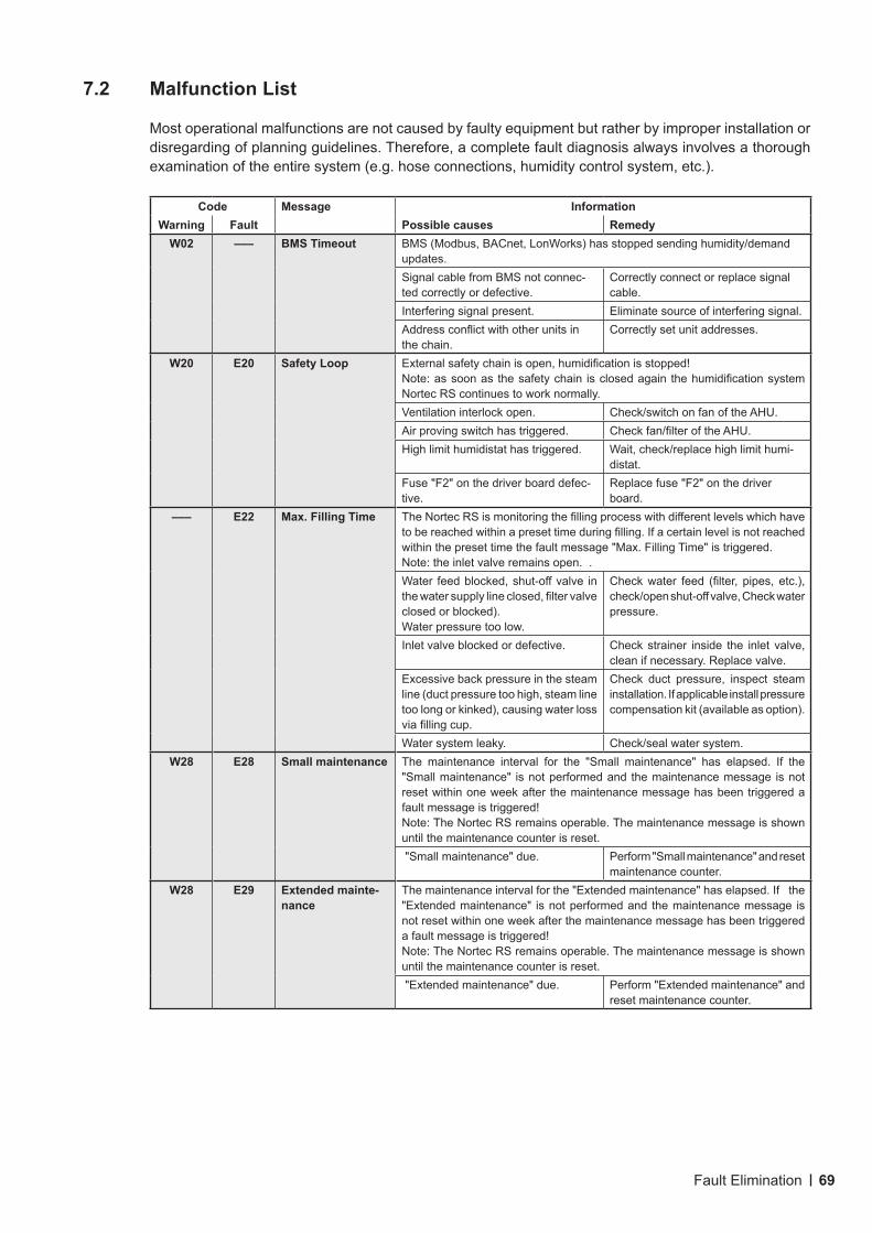
69Fault Elimination
7.2 Malfunction List
Most operational malfunctions are not caused by faulty equipment but rather by improper installation or disregarding of planning guidelines. Therefore, a complete fault diagnosis always involves a thorough examination of the entire system (e.g. hose connections, humidity control system, etc.).
Code Message InformationWarning Fault Possible causes Remedy
W02 ––– BMS Timeout BMS (Modbus, BACnet, LonWorks) has stopped sending humidity/demand updates.Signal cable from BMS not connec-ted correctly or defective.
Correctly connect or replace signal cable.
Interfering signal present. Eliminate source of interfering signal.Address conflict with other units in the chain.
Correctly set unit addresses.
W20 E20 Safety Loop External safety chain is open, humidification is stopped! Note: as soon as the safety chain is closed again the humidification system Nortec RS continues to work normally.Ventilation interlock open. Check/switch on fan of the AHU.Air proving switch has triggered. Check fan/filter of the AHU.High limit humidistat has triggered. Wait, check/replace high limit humi-
distat.Fuse "F2" on the driver board defec-tive.
Replace fuse "F2" on the driver board.
––– E22 Max. Filling Time The Nortec RS is monitoring the filling process with different levels which have to be reached within a preset time during filling. If a certain level is not reached within the preset time the fault message "Max. Filling Time" is triggered.Note: the inlet valve remains open. .Water feed blocked, shut-off valve in the water supply line closed, filter valve closed or blocked).Water pressure too low.
Check water feed (filter, pipes, etc.), check/open shut-off valve, Check water pressure.
Inlet valve blocked or defective. Check strainer inside the inlet valve, clean if necessary. Replace valve.
Excessive back pressure in the steam line (duct pressure too high, steam line too long or kinked), causing water loss via filling cup.
Check duct pressure, inspect steam installation. If applicable install pressure compensation kit (available as option).
Water system leaky. Check/seal water system.W28 E28 Small maintenance The maintenance interval for the "Small maintenance" has elapsed. If the
"Small maintenance" is not performed and the maintenance message is not reset within one week after the maintenance message has been triggered a fault message is triggered!Note: The Nortec RS remains operable. The maintenance message is shown until the maintenance counter is reset. "Small maintenance" due. Perform "Small maintenance" and reset
maintenance counter.W28 E29 Extended mainte-
nanceThe maintenance interval for the "Extended maintenance" has elapsed. If the "Extended maintenance" is not performed and the maintenance message is not reset within one week after the maintenance message has been triggered a fault message is triggered!Note: The Nortec RS remains operable. The maintenance message is shown until the maintenance counter is reset. "Extended maintenance" due. Perform "Extended maintenance" and
reset maintenance counter.
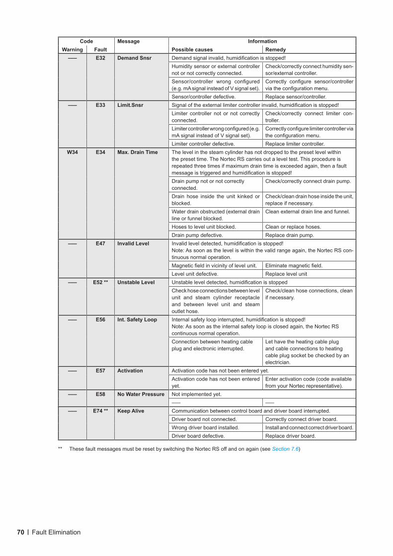
70 Fault Elimination
Code Message InformationWarning Fault Possible causes Remedy––– E32 Demand Snsr Demand signal invalid, humidification is stopped!
Humidity sensor or external controller not or not correctly connected.
Check/correctly connect humidity sen-sor/external controller.
Sensor/controller wrong configured (e.g. mA signal instead of V signal set).
Correctly configure sensor/controller via the configuration menu.
Sensor/controller defective. Replace sensor/controller.––– E33 Limit.Snsr Signal of the external limiter controller invalid, humidification is stopped!
Limiter controller not or not correctly connected.
Check/correctly connect limiter con-troller.
Limiter controller wrong configured (e.g. mA signal instead of V signal set).
Correctly configure limiter controller via the configuration menu.
Limiter controller defective. Replace limiter controller.W34 E34 Max. Drain Time The level in the steam cylinder has not dropped to the preset level within
the preset time. The Nortec RS carries out a level test. This procedure is repeated three times if maximum drain time is exceeded again, then a fault message is triggered and humidification is stopped! Drain pump not or not correctly connected.
Check/correctly connect drain pump.
Drain hose inside the unit kinked or blocked.
Check/clean drain hose inside the unit, replace if necessary.
Water drain obstructed (external drain line or funnel blocked.
Clean external drain line and funnel.
Hoses to level unit blocked. Clean or replace hoses.Drain pump defective. Replace drain pump.
––– E47 Invalid Level Invalid level detected, humidification is stopped!Note: As soon as the level is within the valid range again, the Nortec RS con-tinuous normal operation.Magnetic field in vicinity of level unit. Eliminate magnetic field.Level unit defective. Replace level unit
––– E52 ** Unstable Level Unstable level detected, humidification is stoppedCheck hose connections between level unit and steam cylinder receptacle and between level unit and steam outlet hose.
Check/clean hose connections, clean if necessary.
––– E56 Int. Safety Loop Internal safety loop interrupted, humidification is stopped! Note: As soon as the internal safety loop is closed again, the Nortec RS continuous normal operation.Connection between heating cable plug and electronic interrupted.
Let have the heating cable plug and cable connections to heating cable plug socket be checked by an electrician.
––– E57 Activation Activation code has not been entered yet.Activation code has not been entered yet.
Enter activation code (code available from your Nortec representative).
––– E58 No Water Pressure Not implemented yet.––– –––
––– E74 ** Keep Alive Communication between control board and driver board interrupted.Driver board not connected. Correctly connect driver board.Wrong driver board installed. Install and connect correct driver board.Driver board defective. Replace driver board.
** These fault messages must be reset by switching the Nortec RS off and on again (see Section 7.6)
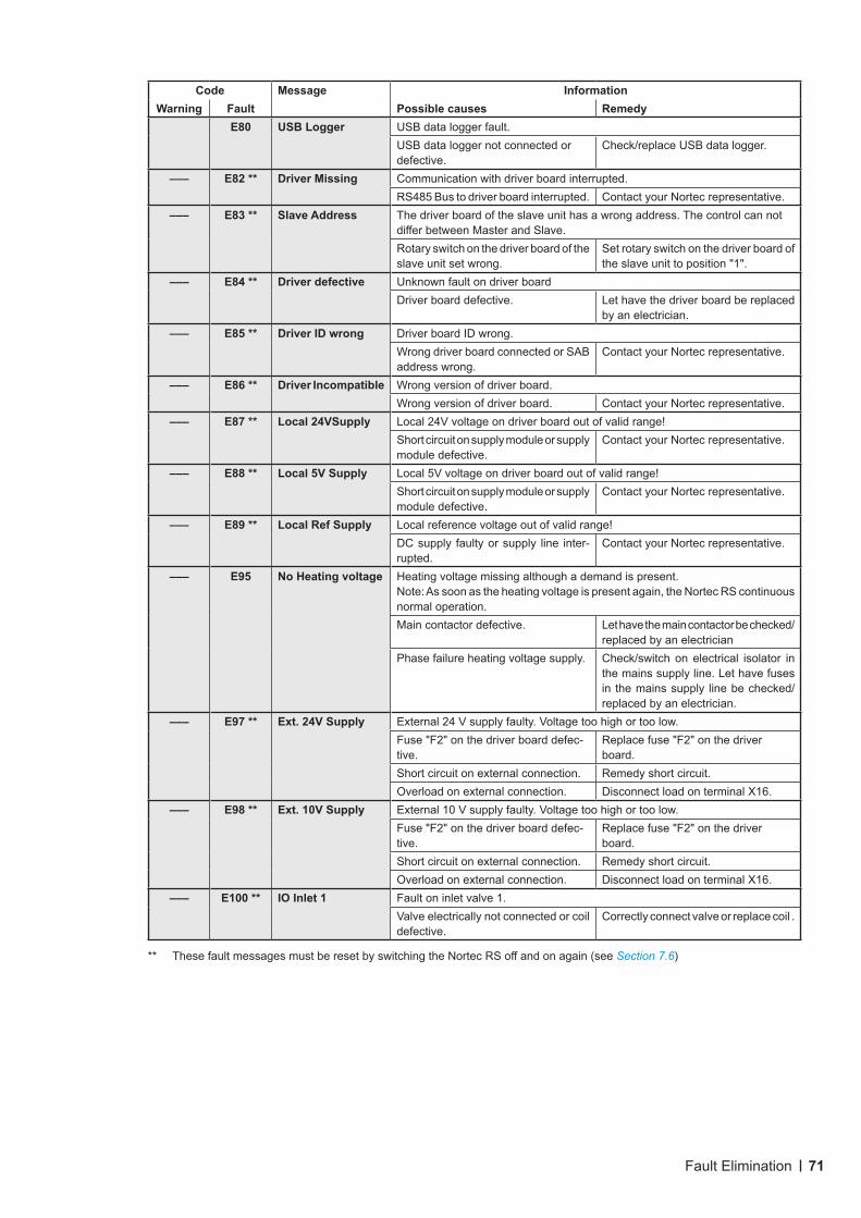
71Fault Elimination
Code Message InformationWarning Fault Possible causes Remedy
E80 USB Logger USB data logger fault.USB data logger not connected or defective.
Check/replace USB data logger.
––– E82 ** Driver Missing Communication with driver board interrupted.RS485 Bus to driver board interrupted. Contact your Nortec representative.
––– E83 ** Slave Address The driver board of the slave unit has a wrong address. The control can not differ between Master and Slave.Rotary switch on the driver board of the slave unit set wrong.
Set rotary switch on the driver board of the slave unit to position "1".
––– E84 ** Driver defective Unknown fault on driver boardDriver board defective. Let have the driver board be replaced
by an electrician.––– E85 ** Driver ID wrong Driver board ID wrong.
Wrong driver board connected or SAB address wrong.
Contact your Nortec representative.
––– E86 ** Driver Incompatible Wrong version of driver board.Wrong version of driver board. Contact your Nortec representative.
––– E87 ** Local 24VSupply Local 24V voltage on driver board out of valid range!Short circuit on supply module or supply module defective.
Contact your Nortec representative.
––– E88 ** Local 5V Supply Local 5V voltage on driver board out of valid range!Short circuit on supply module or supply module defective.
Contact your Nortec representative.
––– E89 ** Local Ref Supply Local reference voltage out of valid range!DC supply faulty or supply line inter-rupted.
Contact your Nortec representative.
––– E95 No Heating voltage Heating voltage missing although a demand is present.Note: As soon as the heating voltage is present again, the Nortec RS continuous normal operation.Main contactor defective. Let have the main contactor be checked/
replaced by an electricianPhase failure heating voltage supply. Check/switch on electrical isolator in
the mains supply line. Let have fuses in the mains supply line be checked/replaced by an electrician.
––– E97 ** Ext. 24V Supply External 24 V supply faulty. Voltage too high or too low.Fuse "F2" on the driver board defec-tive.
Replace fuse "F2" on the driver board.
Short circuit on external connection. Remedy short circuit.Overload on external connection. Disconnect load on terminal X16.
––– E98 ** Ext. 10V Supply External 10 V supply faulty. Voltage too high or too low.Fuse "F2" on the driver board defec-tive.
Replace fuse "F2" on the driver board.
Short circuit on external connection. Remedy short circuit.Overload on external connection. Disconnect load on terminal X16.
––– E100 ** IO Inlet 1 Fault on inlet valve 1.Valve electrically not connected or coil defective.
Correctly connect valve or replace coil .
** These fault messages must be reset by switching the Nortec RS off and on again (see Section 7.6)
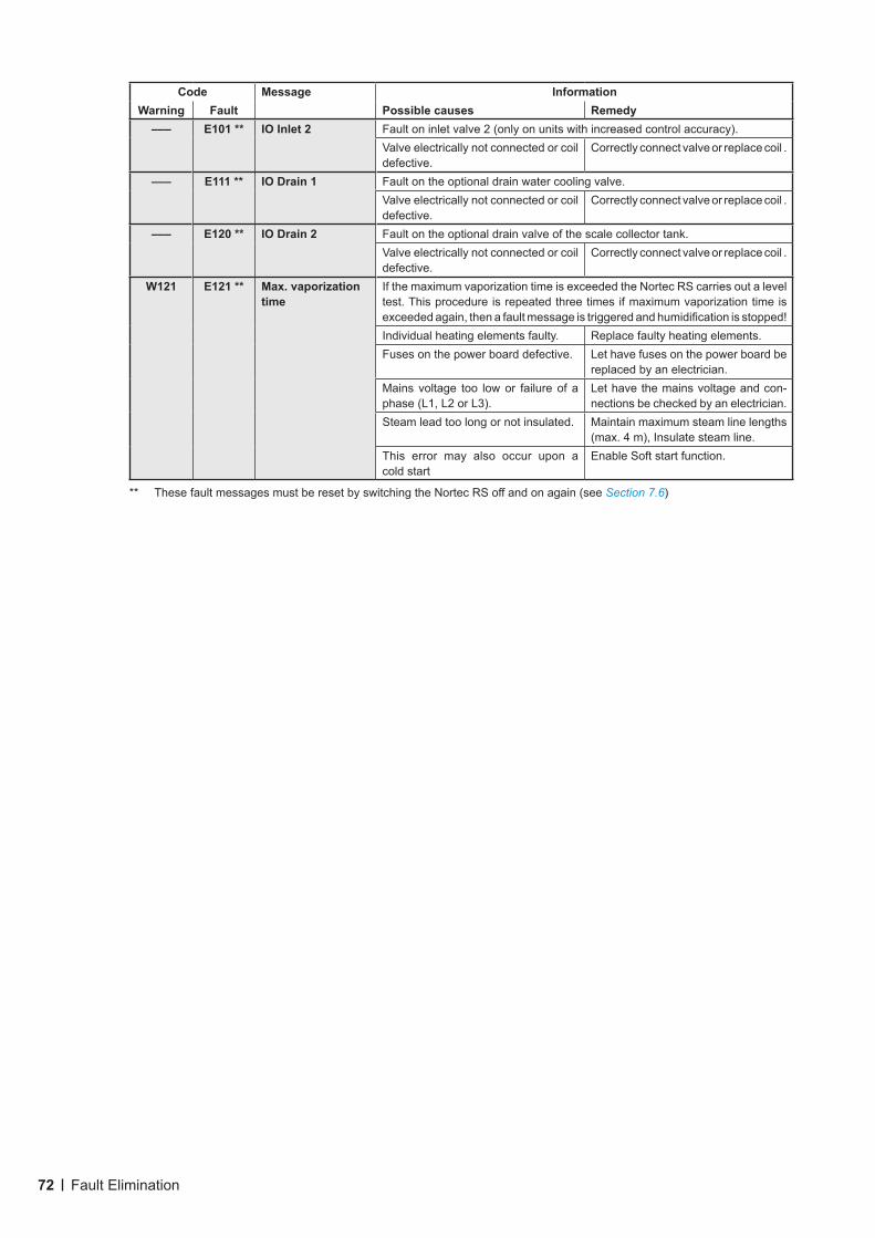
72 Fault Elimination
Code Message InformationWarning Fault Possible causes Remedy––– E101 ** IO Inlet 2 Fault on inlet valve 2 (only on units with increased control accuracy).
Valve electrically not connected or coil defective.
Correctly connect valve or replace coil .
––– E111 ** IO Drain 1 Fault on the optional drain water cooling valve.Valve electrically not connected or coil defective.
Correctly connect valve or replace coil .
––– E120 ** IO Drain 2 Fault on the optional drain valve of the scale collector tank.Valve electrically not connected or coil defective.
Correctly connect valve or replace coil .
W121 E121 ** Max.vaporizationtime
If the maximum vaporization time is exceeded the Nortec RS carries out a level test. This procedure is repeated three times if maximum vaporization time is exceeded again, then a fault message is triggered and humidification is stopped! Individual heating elements faulty. Replace faulty heating elements.Fuses on the power board defective. Let have fuses on the power board be
replaced by an electrician.Mains voltage too low or failure of a phase (L1, L2 or L3).
Let have the mains voltage and con-nections be checked by an electrician.
Steam lead too long or not insulated. Maintain maximum steam line lengths (max. 4 m), Insulate steam line.
This error may also occur upon a cold start
Enable Soft start function.
** These fault messages must be reset by switching the Nortec RS off and on again (see Section 7.6)
73Fault Elimination
7.3 Saving Fault and Service Histories to a USB Memory Stick
The fault and service histories of the Nortec RS can be saved to a USB memory stick for logging and further analysis. For this purpose proceed as follows:
To save the fault and service histories to a USB memory stick, proceed as follows:
1. Disconnect power supply to control unit by switching off the electrical isolator in the mains supply line. Secure electrical isolator against inadvertent power-up.
2. Unlock retaining screw of front cover of the control unit, then remove front cover.
3. Swivel control board assembly 90°outwards.
4. Connect USB memory stick (max. length 3 in/75 mm) to USB port on the control board.
3. Swivel control board assembly 90°inwards.
6. Relocate front cover on control unit and lock it with the retaining screw.
7. Switch on power supply to control unit.
8. Access the main menu, then select "Export History" function in the "Service" submenu. The data are saved as CSV table on the USB memory stick. The CSV table can be processed with a spread-sheet program on a PC.
9. When the data has been saved, repeat steps 1 to 6 once more to remove the USB memory stick.
7.4 Notes on Fault Elimination
– For the elimination of faults set the Nortec RS out of operation (see Section 4.5 – Taking the Unit Out of Operation) and disconnect it from the mains.
DANGER!
Make sure the Nortec RS is separated from the mains (check with voltage detector) and the shut-off valve in the water supply line is closed.
– The elimination of faults must be carried out by qualified and well trained professionals only.Malfunctions relating to the electrical installation must be repaired only by an authorized electrician or the Nortec service technician.
CAUTION!
Electronic components are very sensitive to electrostatic discharge. When carrying out repairs to the Nortec RS, appropriate measures (ESD-protection) must be taken to prevent damage to electronic components.
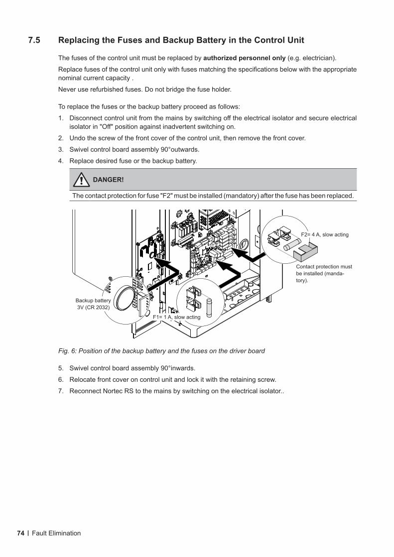
74 Fault Elimination
7.5 Replacing the Fuses and Backup Battery in the Control Unit
The fuses of the control unit must be replaced by authorizedpersonnelonly (e.g. electrician).
Replace fuses of the control unit only with fuses matching the specifications below with the appropriate nominal current capacity .
Never use refurbished fuses. Do not bridge the fuse holder.
To replace the fuses or the backup battery proceed as follows:
1. Disconnect control unit from the mains by switching off the electrical isolator and secure electrical isolator in "Off" position against inadvertent switching on.
2. Undo the screw of the front cover of the control unit, then remove the front cover.
3. Swivel control board assembly 90°outwards.
4. Replace desired fuse or the backup battery.
DANGER!
The contact protection for fuse "F2" must be installed (mandatory) after the fuse has been replaced.
Fig. 6: Position of the backup battery and the fuses on the driver board
5. Swivel control board assembly 90°inwards.
6. Relocate front cover on control unit and lock it with the retaining screw.
7. Reconnect Nortec RS to the mains by switching on the electrical isolator..
Backup battery3V (CR 2032)
F2= 4 A, slow acting
F1= 1 A, slow acting
Contact protection must be installed (manda-tory).
75Fault Elimination
7.6 Resetting the Fault Indication
To reset the error indication (red LED light, operating status indication shows "Stop"):
1. Switch off the Nortec RS via the unit switch.
2. Wait approx. 5 seconds, then switch on the Nortec RS again.
Note: If the fault has not been eliminated, the fault indication reappears after a short while.
76 Taking Out of Service/Disposal
8 Taking Out of Service/Disposal
8.1 Taking Out of Service
If the Nortec RS must be replaced or if the Nortec RS is not needed any more, proceed as follows:
1. Take the Nortec RS out of operation as described in Section 4.5 – Taking the Unit Out of Operation.
2. Have the Nortec RS (and if applicable othe system components) unmounted by a qualified service technician.
8.2 Disposal/Recycling
Components not used any more must not be disposed of in the domestic waste. Please dispose of the individual components in accordance with local regulations at the authorised collecting point.
If you have any questions, please contact the responsible authority or your local Nortec representative.
Thank you for your contribution to environmental protection.
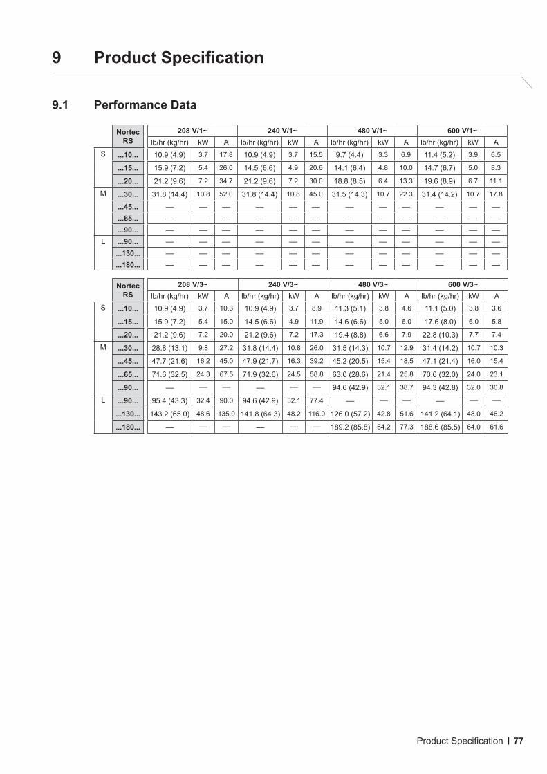
77Product Specification
9 ProductSpecification
9.1 Performance Data
Nortec RS
208 V/1~ 240 V/1~ 480 V/1~ 600 V/1~lb/hr (kg/hr) kW A lb/hr (kg/hr) kW A lb/hr (kg/hr) kW A lb/hr (kg/hr) kW A
S ...10... 10.9 (4.9) 3.7 17.8 10.9 (4.9) 3.7 15.5 9.7 (4.4) 3.3 6.9 11.4 (5.2) 3.9 6.5
...15... 15.9 (7.2) 5.4 26.0 14.5 (6.6) 4.9 20.6 14.1 (6.4) 4.8 10.0 14.7 (6.7) 5.0 8.3
...20... 21.2 (9.6) 7.2 34.7 21.2 (9.6) 7.2 30.0 18.8 (8.5) 6.4 13.3 19.6 (8.9) 6.7 11.1
M ...30... 31.8 (14.4) 10.8 52.0 31.8 (14.4) 10.8 45.0 31.5 (14.3) 10.7 22.3 31.4 (14.2) 10.7 17.8
...45... –– –– –– –– –– –– –– –– –– –– –– ––
...65... –– –– –– –– –– –– –– –– –– –– –– ––
...90... –– –– –– –– –– –– –– –– –– –– –– ––L ...90... –– –– –– –– –– –– –– –– –– –– –– ––
...130... –– –– –– –– –– –– –– –– –– –– –– ––
...180... –– –– –– –– –– –– –– –– –– –– –– ––
Nortec RS
208 V/3~ 240 V/3~ 480 V/3~ 600 V/3~lb/hr (kg/hr) kW A lb/hr (kg/hr) kW A lb/hr (kg/hr) kW A lb/hr (kg/hr) kW A
S ...10... 10.9 (4.9) 3.7 10.3 10.9 (4.9) 3.7 8.9 11.3 (5.1) 3.8 4.6 11.1 (5.0) 3.8 3.6
...15... 15.9 (7.2) 5.4 15.0 14.5 (6.6) 4.9 11.9 14.6 (6.6) 5.0 6.0 17.6 (8.0) 6.0 5.8
...20... 21.2 (9.6) 7.2 20.0 21.2 (9.6) 7.2 17.3 19.4 (8.8) 6.6 7.9 22.8 (10.3) 7.7 7.4
M ...30... 28.8 (13.1) 9.8 27.2 31.8 (14.4) 10.8 26.0 31.5 (14.3) 10.7 12.9 31.4 (14.2) 10.7 10.3
...45... 47.7 (21.6) 16.2 45.0 47.9 (21.7) 16.3 39.2 45.2 (20.5) 15.4 18.5 47.1 (21.4) 16.0 15.4
...65... 71.6 (32.5) 24.3 67.5 71.9 (32.6) 24.5 58.8 63.0 (28.6) 21.4 25.8 70.6 (32.0) 24.0 23.1
...90... –– –– –– –– –– –– 94.6 (42.9) 32.1 38.7 94.3 (42.8) 32.0 30.8
L ...90... 95.4 (43.3) 32.4 90.0 94.6 (42.9) 32.1 77.4 –– –– –– –– –– ––
...130... 143.2 (65.0) 48.6 135.0 141.8 (64.3) 48.2 116.0 126.0 (57.2) 42.8 51.6 141.2 (64.1) 48.0 46.2
...180... –– –– –– –– –– –– 189.2 (85.8) 64.2 77.3 188.6 (85.5) 64.0 61.6
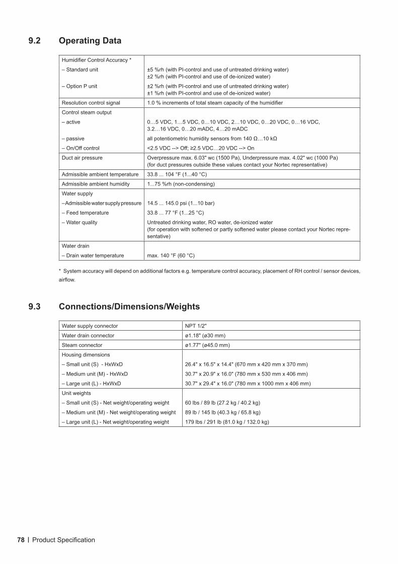
78 Product Specification
9.2 Operating Data
Humidifier Control Accuracy *
– Standard unit ±5 %rh (with PI-control and use of untreated drinking water)±2 %rh (with PI-control and use of de-ionized water)
– Option P unit ±2 %rh (with PI-control and use of untreated drinking water)±1 %rh (with PI-control and use of de-ionized water)
Resolution control signal 1.0 % increments of total steam capacity of the humidifier
Control steam output
– active 0…5 VDC, 1…5 VDC, 0…10 VDC, 2…10 VDC, 0…20 VDC, 0…16 VDC, 3.2…16 VDC, 0…20 mADC, 4…20 mADC
– passive all potentiometric humidity sensors from 140 Ω…10 kΩ
– On/Off control <2.5 VDC --> Off; ≥2.5 VDC…20 VDC --> On
Duct air pressure Overpressure max. 6.03" wc (1500 Pa), Underpressure max. 4.02" wc (1000 Pa) (for duct pressures outside these values contact your Nortec representative)
Admissible ambient temperature 33.8 ... 104 °F (1...40 °C)
Admissible ambient humidity 1...75 %rh (non-condensing)
Water supply
– Admissible water supply pressure 14.5 ... 145.0 psi (1...10 bar)
– Feed temperature 33.8 ... 77 °F (1...25 °C)
– Water quality Untreated drinking water, RO water, de-ionized water(for operation with softened or partly softened water please contact your Nortec repre-sentative)
Water drain
– Drain water temperature max. 140 °F (60 °C)
* System accuracy will depend on additional factors e.g. temperature control accuracy, placement of RH control / sensor devices, airflow.
9.3 Connections/Dimensions/Weights
Water supply connector NPT 1/2"
Water drain connector ø1.18" (ø30 mm)
Steam connector ø1.77" (ø45.0 mm)
Housing dimensions
– Small unit (S) - HxWxD 26.4" x 16.5" x 14.4" (670 mm x 420 mm x 370 mm)
– Medium unit (M) - HxWxD 30.7" x 20.9" x 16.0" (780 mm x 530 mm x 406 mm)
– Large unit (L) - HxWxD 30.7" x 29.4" x 16.0" (780 mm x 1000 mm x 406 mm)
Unit weights
– Small unit (S) - Net weight/operating weight 60 lbs / 89 lb (27.2 kg / 40.2 kg)
– Medium unit (M) - Net weight/operating weight 89 lb / 145 lb (40.3 kg / 65.8 kg)
– Large unit (L) - Net weight/operating weight 179 lbs / 291 lb (81.0 kg / 132.0 kg)
WarrantyNortec Humidity Inc. and/or Nortec Humidity Ltd. (hereinafter collectively referred to as THE COMPANY), warrant for a period of two years after installation or 30 months from manufacturer’s ship date, whichever date is earlier, that THE COMPANY’s manufactured and assembled products, not otherwise expressly warranted, are free from defects in material and workmanship. No warranty is made against corrosion, deterioration, or suitability of substituted materials used as a result of compliance with government regulations.
THE COMPANY’s obligations and liabilities under this warranty are limited to furnishing replacement parts to the customer, F.O.B. THE COMPANY’s factory, providing the defective part(s) is returned freight prepaid by the customer. Parts used for repairs are warranted for the balance of the term of the warranty on the original humidifier or 90 days, whichever is longer.
The warranties set forth herein are in lieu of all other warranties expressed or implied by law. No liability whatsoever shall be attached to THE COMPANY until said products have been paid for in full and then said liability shall be limited to the original purchase price for the product. Any further warranty must be in writing, signed by an officer of THE COMPANY.
THE COMPANY’s limited warranty on accessories, not of the companies manufacture, such as controls, humidistats, pumps, etc. is limited to the warranty of the original equipment manufacturer from date of original shipment of humidifier.
THE COMPANY makes no warranty and assumes no liability unless the equipment is installed in strict accordance with a copy of the catalog and installation manual in effect at the date of purchase and by a contractor approved by THE COMPANY to install such equipment.
THE COMPANY makes no warranty and assumes no liability whatsoever for consequential damage or damage resulting directly from misapplication, incorrect sizing or lack of proper maintenance of the equipment.
THE COMPANY makes no warranty and assumes no liability whatsoever for damage resulting from freezing of the humidifier, supply lines, drain lines, or steam distribution systems.
THE COMPANY retains the right to change the design, specification and performance criteria of its products without notice or obligation.
U.S.A.826 Proctor AvenueOgdensburg, NY 13669
CANADA2740 Fenton RoadOttawa, Ontario K1T 3T7
TEL: 1.866.NORTEC1FAX: 613.822.7964
EMAIL: [email protected]: www.humidity.com
![Nortec MES2 Electrode Steam Humidifier · B. Complete and operable humidification system [which meets applicable building codes]. C. Equipment start-up and project inspection by qualified](https://static.fdocuments.us/doc/165x107/5e75e90072bf2300d654e16e/nortec-mes2-electrode-steam-humidifier-b-complete-and-operable-humidification-system.jpg)