NONLINEAR DYNAMIC RESPONSE AND DUCTILITY ...research.iaun.ac.ir/pd/parhamold/pdfs/PaperM_7043.pdfA...
14
Iranian Journal of Science & Technology, Transaction B: Engineering, Vol. 34, No. B4, pp 371-384 Printed in The Islamic Republic of Iran, 2010 © Shiraz University NONLINEAR DYNAMIC RESPONSE AND DUCTILITY REQUIREMENTS OF A TYPICAL STEEL PLATE SHEAR WALL SUBJECTED TO EL CENTRO EARTHQUAKE * P. MEMARZADEH, M. M. SAADATPOUR AND M. AZHARI ** Dept. of Civil Engineering, Isfahan University of Technology, Isfahan 8415683111, I. R. of Iran Email: [email protected] Abstract– In the present research, an explicit dynamic analysis is conducted on a typical multi- storey Steel Plate Shear Wall (SPSW) designed according to AISC requirements. The SPSW model is subjected to a base earthquake acceleration record to simulate the time history response of the structure. The analysis utilizes a finite element method involving both material and geometric nonlinearities. The energy dissipation behavior and distribution of storey shear over height of the model are investigated through time history response of the system. In addition, this paper proposes a new definition of energy ductility, which can be used in the investigation of the dynamic response of SPSWs. The ductility demand based on the proposed definition as well as shear resistance contribution of the web plate and Vertical Boundary Elements (VBE) of SPSW are evaluated. Keywords– Shear wall, steel plate, dynamic response, transient, energy dissipation, energy ductility 1. INTRODUCTION In 1935 Tanabashi proposed an advanced theory which suggested that the earthquake resistant capacity of a structure should be measured by the amount of energy dissipated through the ductility of the structure before collapse [1]. Before the 1960s the ductility notion was used only for characterizing the material behavior. After Housner’s studies of earthquake problems, this concept has been extended to a structure level [2]. The plastic dissipation causes decreasing in the elastic strain energy and subsequently the developed seismic forces leading, in most cases, to a more economic design. In order to secure a stable hysteretic behavior under reversed loading, the structure must be designed for ductility in addition to stiffness. The objective of adding an energy dissipation element to new and exiting construction is to dissipate much of the earthquake-induced energy in disposable elements not forming part of a gravity framing system. As steel is a ductile material, steel systems are well suited to providing the required ductility, as long as the inelastic demands on the steel material occur in appropriate portions of the structure. A Steel Plate Shear Wall (SPSW) is a lateral-load-resisting system consisting of vertical steel plate infills connected to the surrounding beams and columns and installed in one or more bays along the full height of the structure. SPSWs offer significant advantages over many other systems in terms of cost, performance and ease of design. SPSWs also typically resist lateral loads, primarily through diagonal tension in the web and overturning forces in the adjoining columns. In addition to new construction, steel web plates have been added to retrofit existing frame buildings requiring additional strength and stiffness. ∗ Received by the editors March 1, 2009; Accepted August 24, 2009. ∗∗ Corresponding author
Transcript of NONLINEAR DYNAMIC RESPONSE AND DUCTILITY ...research.iaun.ac.ir/pd/parhamold/pdfs/PaperM_7043.pdfA...
Iranian Journal of Science & Technology, Transaction B: Engineering, Vol. 34, No. B4, pp 371-384 Printed in The Islamic Republic of Iran, 2010 © Shiraz University
NONLINEAR DYNAMIC RESPONSE AND DUCTILITY REQUIREMENTS OF A TYPICAL STEEL PLATE SHEAR WALL SUBJECTED TO
EL CENTRO EARTHQUAKE*
P. MEMARZADEH, M. M. SAADATPOUR AND M. AZHARI** Dept. of Civil Engineering, Isfahan University of Technology, Isfahan 8415683111, I. R. of Iran
Email: [email protected]
Abstract– In the present research, an explicit dynamic analysis is conducted on a typical multi-storey Steel Plate Shear Wall (SPSW) designed according to AISC requirements. The SPSW model is subjected to a base earthquake acceleration record to simulate the time history response of the structure. The analysis utilizes a finite element method involving both material and geometric nonlinearities. The energy dissipation behavior and distribution of storey shear over height of the model are investigated through time history response of the system. In addition, this paper proposes a new definition of energy ductility, which can be used in the investigation of the dynamic response of SPSWs. The ductility demand based on the proposed definition as well as shear resistance contribution of the web plate and Vertical Boundary Elements (VBE) of SPSW are evaluated.
Keywords– Shear wall, steel plate, dynamic response, transient, energy dissipation, energy ductility
1. INTRODUCTION
In 1935 Tanabashi proposed an advanced theory which suggested that the earthquake resistant capacity of a structure should be measured by the amount of energy dissipated through the ductility of the structure before collapse [1]. Before the 1960s the ductility notion was used only for characterizing the material behavior. After Housner’s studies of earthquake problems, this concept has been extended to a structure level [2].
The plastic dissipation causes decreasing in the elastic strain energy and subsequently the developed seismic forces leading, in most cases, to a more economic design. In order to secure a stable hysteretic behavior under reversed loading, the structure must be designed for ductility in addition to stiffness.
The objective of adding an energy dissipation element to new and exiting construction is to dissipate much of the earthquake-induced energy in disposable elements not forming part of a gravity framing system. As steel is a ductile material, steel systems are well suited to providing the required ductility, as long as the inelastic demands on the steel material occur in appropriate portions of the structure.
A Steel Plate Shear Wall (SPSW) is a lateral-load-resisting system consisting of vertical steel plate infills connected to the surrounding beams and columns and installed in one or more bays along the full height of the structure. SPSWs offer significant advantages over many other systems in terms of cost, performance and ease of design. SPSWs also typically resist lateral loads, primarily through diagonal tension in the web and overturning forces in the adjoining columns. In addition to new construction, steel web plates have been added to retrofit existing frame buildings requiring additional strength and stiffness.
∗Received by the editors March 1, 2009; Accepted August 24, 2009. ∗∗Corresponding author
P. Memarzadeh et al.
Iranian Journal of Science & Technology, Volume 34, Number B4 August 2010
372
Systems designed for high-seismic loading are expected to undergo multiple cycles of loading into the inelastic range with controlled damage accepted as a means of dissipating the energy of the earthquake. Web plates in SPSWs provide a large area of steel to dissipate the system energy by plasticity, causing the ductility of the system. For stability consideration, the high-seismic design of SPSW is based on confining ductility demands to the web plate and to plastic hinges in the Horizontal Boundary Element (HBE) at the Vertical Boundary Element (VBE) face. In this regard, AISC 341 [3] provides requirements for designing SPSW by means of a capacity-design concept [4] (i.e. in a SPSW, the capacity design is to design the system in such a way that the steel infill plate yields and acts as a fuse, while the column remains elastic for structural integrity of the system.) in which boundary elements are designed for forces corresponding to the full yield strength of the web plate.
In the design of high-rise buildings in seismic areas, there is an increasing demand for reliable structural systems with predictable behavior. For such systems, the desired behavior remains the tension yielding of the web plates. The distribution of inelastic demand between floors requires that web plates be designed with a similar overstrength. If web plates at some levels are designed with overstrength much greater than those at other levels, the high-overstrength web plates will not participate in providing system ductility, and the seismic drift demands on the other levels will be greater. Un-even drift distribution between stories can cause large flexural demands in the Vertical Boundary Elements (VBE), perhaps leading to their yielding and the formation of a storey mechanism [4]. Thus, it is recommended to proportion the web plates to storey shear as closely as possible and not to provide unnecessary overstrength [5].
The objective of this study is the evaluation of the ductility imposed on the storey plates of a typical SPSW when subjected to the El Centro earthquake record. In addition, other seismic performances of the building including storey displacements and drifts, as well as interstorey shear and internal forces over the height of VBE are evaluated. The subject of the investigation is a typical nine-storey SPSW building designed according to AISC [3, 6] requirements. Ref. [7] presents some experimental studies on the behavior of infilled frames.
2. METHODOLOGY
The methodology is based on a finite element model in which the effects of geometric and material nonlinearities are considered. The Logarithmic strain and the Cauchy stress which are conjugate with each other are used in the present analysis since, for metals such as steel, the elastic part of the strain can be assumed to be small [8]. Strain rate is the symmetric part of the velocity gradient decomposition and the Green-Naghdi rate is assumed as the stress rate [8].
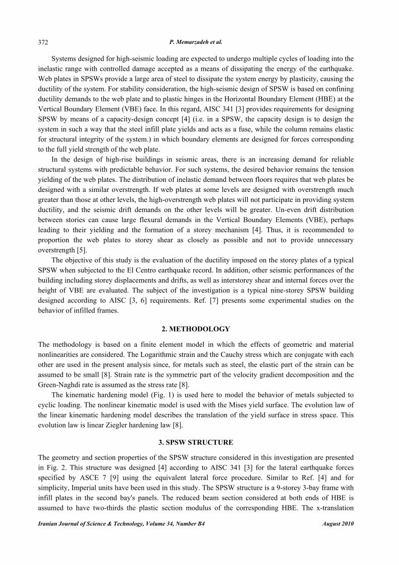
The kinematic hardening model (Fig. 1) is used here to model the behavior of metals subjected to cyclic loading. The nonlinear kinematic model is used with the Mises yield surface. The evolution law of the linear kinematic hardening model describes the translation of the yield surface in stress space. This evolution law is linear Ziegler hardening law [8].
3. SPSW STRUCTURE
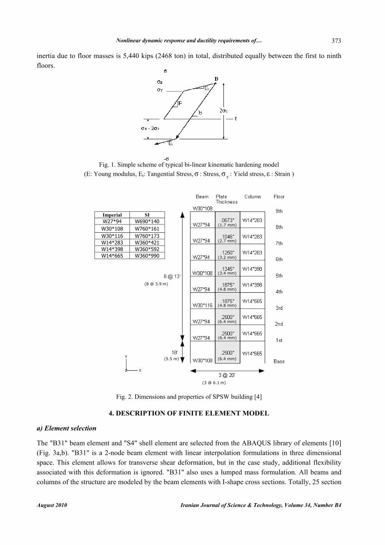
The geometry and section properties of the SPSW structure considered in this investigation are presented in Fig. 2. This structure was designed [4] according to AISC 341 [3] for the lateral earthquake forces specified by ASCE 7 [9] using the equivalent lateral force procedure. Similar to Ref. [4] and for simplicity, Imperial units have been used in this study. The SPSW structure is a 9-storey 3-bay frame with infill plates in the second bay's panels. The reduced beam section considered at both ends of HBE is assumed to have two-thirds the plastic section modulus of the corresponding HBE. The x-translation
Nonlinear dynamic response and ductility requirements of…
August 2010 Iranian Journal of Science & Technology, Volume 34, Number B4
373
inertia due to floor masses is 5,440 kips (2468 ton) in total, distributed equally between the first to ninth floors.
Fig. 1. Simple scheme of typical bi-linear kinematic hardening model
(E: Young modulus, Et: Tangential Stress,σ : Stress, yσ : Yield stress, ε : Strain )
Fig. 2. Dimensions and properties of SPSW building [4]
4. DESCRIPTION OF FINITE ELEMENT MODEL
a) Element selection
The "B31" beam element and "S4" shell element are selected from the ABAQUS library of elements [10] (Fig. 3a,b). "B31" is a 2-node beam element with linear interpolation formulations in three dimensional space. This element allows for transverse shear deformation, but in the case study, additional flexibility associated with this deformation is ignored. "B31" also uses a lumped mass formulation. All beams and columns of the structure are modeled by the beam elements with I-shape cross sections. Totally, 25 section
(1.7 mm)
(2.7 mm)
(3.2 mm)
(3.4 mm)
(4.8 mm)
(4.8 mm)
(6.4 mm)
(6.4 mm)
(8 @ 3.9 m)
(6.4 mm)
(3 @ 6.1 m)
(5.5 m)
SI Imperial W690*140 W27*94 W760*161 W30*108 W760*173 W30*116 W360*421 W14*283 W360*592 W14*398 W360*990 W14*665
P. Memarzadeh et al.
Iranian Journal of Science & Technology, Volume 34, Number B4 August 2010
374
points are specified to be used for integration; 9 points in web, 9 in each flange. Figure 3c shows Simpson's integration points in an I-shape cross section of a beam element [8, 10].
(a) (b) (c)
Fig. 3. Integration point in (a) "B31" beam element and (b) "S4" shell element (c) I-shape cross section [8,10]
"S4" is a general-purpose 4-node doubly curved shell element, which allows transverse shear
deformation. It uses thick shell theory as the shell thickness increases and becomes discrete Kirchhoff thin shell element as the thickness increases. The transverse shear deformation becomes very small as the shell thickness decreases. This element also uses linear interpolation and accounts for finite membrane strains and arbitrarily large rotations [8].
"S4" uses full integration to form the element stiffness. The mass matrix is integrated exactly. A mesh of 20 by 13 elements (20 elements over the width of the shear wall) is used to model the infill plates except for the first storey infill plate which has a mesh of 20 by 18 elements. The length of the beam elements is selected to match the mesh size in the infill plates. Seven Gaussian integration points through the thickness of the shell elements are used [8].
Both beam and shell elements are based on an updated Lagrangian formulation. Their properties are integrated numerically, so that nonlinear response associated with nonlinear material behavior is tracked accurately when needed. Each node of the elements has six degrees of freedom, namely, three translations
),,( zyx uuu and three rotations ),,( zyx θθθ defined in a global coordinate system [8].
b) Geometry and initial imperfections
The fishplate connection tabs, which are used for the connection of infill plates to the inside flanges of boundary members in the actual building, are not considered in the finite element model since they are not expected to affect the overall behavior of the SPSW [11]. The imperfections can be categorized as the camber and sweep of beams and columns, out-of-plump of the columns and out-of-flatness of the plate. The imperfections associated with the beams and columns are considered small and neglected in the formulation of the finite element model [12].
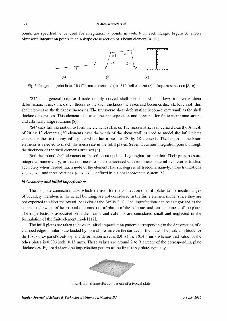
The infill plates are taken to have an initial imperfection pattern corresponding to the deformation of a clamped edges similar plate loaded by normal pressure on the surface of the plate. The peak amplitude for the first storey panel's out-of-plane deformation is set at 0.0183 inch (0.46 mm), whereas that value for the other plates is 0.006 inch (0.15 mm). These values are around 2 to 9 percent of the corresponding plate thicknesses. Figure 4 shows the imperfection pattern of the first storey plate, typically.
Fig. 4. Initial imperfection pattern of a typical plate

Nonlinear dynamic response and ductility requirements of…
August 2010 Iranian Journal of Science & Technology, Volume 34, Number B4
375
c) Boundary conditions All the nodes at the base of the SPSW model are fixed to simulate the rigid boundary condition at the
base of the shear wall. In addition, in order to prevent the local distortion and the out-of-plane deformation at the floor levels, all the nodes at these levels are restrained at zu and yθ degrees of freedom.
d) Material properties
The steel usage in all parts of the SPSW exhibits the classical stress versus strain behavior of hot-
rolled ductile steel with a well-defined yield plateau. A simple rate-independent constitutive behavior that is identical in tension and compression is used. A kinematic hardening model is used for dynamic analysis. Material properties of the boundary members and the plates are assumed with the following specifications [4]:
)345(50),248(36),/8.7(/489,3.0
),200(290),200(000,2933
21
MPaksiFMPaksiFmtonftlb
MPaksiEGPaksiE
ybyp ====
==
ρν (1)
in which ν,, 21 EE and ρ are initial elastic modulus, strain hardening modulus, Poison's ratio and density of steel material, and ybyp FF , are the plate and boundary member yield stresses, respectively. All beam and column material properties are the same as the boundary member properties. Fig. 5 shows the assumed stress-strain relationship of the plate, beam and column materials.
Fig. 5. The assumed stress-strain relationship of the material [4]
e) Damping
Linear bulk viscosity or truncation frequency damping is used to damp the high frequency ringing that leads to unwanted noise in the solution or spurious overshoot in the response amplitude. This damping generates a bulk viscosity pressure that is linear in the volumetric strain [13].
In shells, the linear bulk viscosity also damps the high frequency ringing in the rotational degrees of freedom. Hence, this damping generates a pressure moment which is linear in the mean curvature strain rate [13].
[×6.89 MPa]
2E2E
1E

P. Memarzadeh et al.
Iranian Journal of Science & Technology, Volume 34, Number B4 August 2010
376
5. FREQUENCY ANALYSIS
An eigenvalue extraction is performed on the undamped SPSW structure to calculate the natural frequencies of the frame vibration. Figure 6 shows the frequencies, ,f for various modes of vibration. The −x component of modal participation factor and the modal effective mass of the SPSW finite element
model for various modes of general vibration are also shown in Fig. 6.
Fig. 6. Natural frequencies, participation factors and effective masses for various modes of general vibration
This figure reveals that the 24th, 100th, 194th and 212th modes of general vibration are corresponding
with the 1st, 2nd, 3rd and 4th modes of longitudinal (x-direction) vibration, respectively. These modes have larger participation factors (x-component) and so, play more significant role in the x-direction (longitudinal) vibration than the other modes. Mode shapes corresponding with the mentioned modes are shown in Fig. 7. As shown, the first to fourth modes of longitudinal vibration have the largest effective mass and the largest participation factor (x-component), respectively.
1st mode 2nd mode 3rd mode 4th mode
Hzf x 9043.01 = Hzf x 7761.22 = Hzf x 9129.43 = Hzf x 1586.54 =
Fig. 7. Mode shapes and frequencies of significant modes for longitudinal vibration The frequency analysis presented here is based on assuming an elastic behavior for the materials.
However, it should be noted that, when the SPSW structural material exceeds its elastic limit, the frequency of vibration decreases due to a reduction in stiffness of the material. This is particularly noticeable for SPSWs, since they are designed, as expected, to undergo multiple cycles into the inelastic range.

Nonlinear dynamic response and ductility requirements of…
August 2010 Iranian Journal of Science & Technology, Volume 34, Number B4
377
6. VALIDATION OF THE FINITE ELEMENT MODEL
The finite element model developed for analysis of the SPSW structure is based on a nonlinear dynamic formulation and an explicit strategy is used to obtain the state of the model at each increment without any iteration.
In order to evaluate the validity of the model, the finite element model of the SPSW structure was subjected to a sinusoidal force at the roof level with a frequency of Hz9043.0 (equal to frequency of the first vibration mode) for a time interval of 5 seconds and then, it was allowed to freely vibrate. The lateral displacements of some floors are shown in Fig. 8. This figure shows a resonance in the first 5 second interval and also decreases the free vibration amplitudes due to the damping function.
Fig. 8. Lateral displacements of floors
Also, some other analyses were performed to check the efficiency of the degree of meshing. By
comparing their results for the various energy quantities, shear forces as well as the displacements and accelerations, the efficiency of the considered meshing was confirmed. The mentioned results have been omitted here for brevity.
7. NUMERICAL RESULTS OF THE EXPLICIT DYNAMIC ANALYSIS
The finite element model of the SPSW structure is subjected to a base acceleration recorded in the El Centro earthquake of May 18, 1940 (N-S component). The nonlinear dynamic response to this excitation is computed by digital computer, using the explicit dynamic procedure. The complete response history is determined during the 30 seconds of the earthquake (Fig. 9).
Fig. 9. El Centro earthquake, May 18, 1940, N-S component
a) Energy balance
Energy output is particularly important in checking the accuracy of the solution in an explicit dynamic analysis. An energy balance for the entire model can be written as [13]:
WVKITotal EEEEE −++= (2)
where TotalE is the total energy, VK EE , and WE are kinetic energy, energy dissipated by viscous effects and the external work, respectively; also, )( apsI EEEE ++= is total strain energy; ps EE , and aE are the recoverable strain energy, plastic dissipated energy and artificial strain energy, respectively [13]. The
[×2.54 cm]
P. Memarzadeh et al.
Iranian Journal of Science & Technology, Volume 34, Number B4 August 2010
378
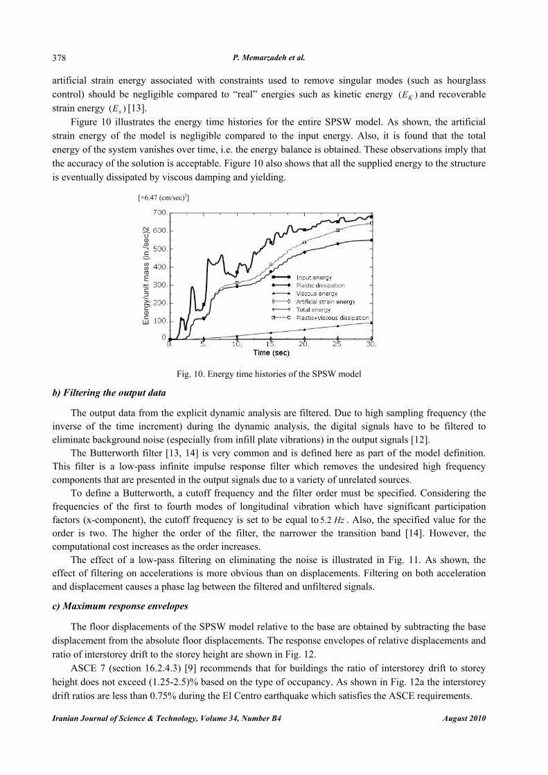
artificial strain energy associated with constraints used to remove singular modes (such as hourglass control) should be negligible compared to “real” energies such as kinetic energy )( KE and recoverable strain energy )( sE [13].
Figure 10 illustrates the energy time histories for the entire SPSW model. As shown, the artificial strain energy of the model is negligible compared to the input energy. Also, it is found that the total energy of the system vanishes over time, i.e. the energy balance is obtained. These observations imply that the accuracy of the solution is acceptable. Figure 10 also shows that all the supplied energy to the structure is eventually dissipated by viscous damping and yielding.
Fig. 10. Energy time histories of the SPSW model
b) Filtering the output data
The output data from the explicit dynamic analysis are filtered. Due to high sampling frequency (the inverse of the time increment) during the dynamic analysis, the digital signals have to be filtered to eliminate background noise (especially from infill plate vibrations) in the output signals [12].
The Butterworth filter [13, 14] is very common and is defined here as part of the model definition. This filter is a low-pass infinite impulse response filter which removes the undesired high frequency components that are presented in the output signals due to a variety of unrelated sources.
To define a Butterworth, a cutoff frequency and the filter order must be specified. Considering the frequencies of the first to fourth modes of longitudinal vibration which have significant participation factors (x-component), the cutoff frequency is set to be equal to Hz2.5 . Also, the specified value for the order is two. The higher the order of the filter, the narrower the transition band [14]. However, the computational cost increases as the order increases.
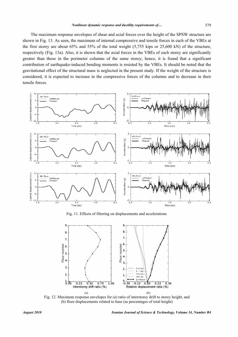
The effect of a low-pass filtering on eliminating the noise is illustrated in Fig. 11. As shown, the effect of filtering on accelerations is more obvious than on displacements. Filtering on both acceleration and displacement causes a phase lag between the filtered and unfiltered signals.
c) Maximum response envelopes
The floor displacements of the SPSW model relative to the base are obtained by subtracting the base
displacement from the absolute floor displacements. The response envelopes of relative displacements and ratio of interstorey drift to the storey height are shown in Fig. 12.
ASCE 7 (section 16.2.4.3) [9] recommends that for buildings the ratio of interstorey drift to storey height does not exceed (1.25-2.5)% based on the type of occupancy. As shown in Fig. 12a the interstorey drift ratios are less than 0.75% during the El Centro earthquake which satisfies the ASCE requirements.
[×6.47 (cm/sec)2]
Nonlinear dynamic response and ductility requirements of…
August 2010 Iranian Journal of Science & Technology, Volume 34, Number B4
379
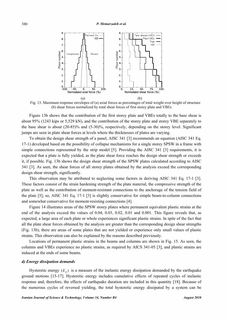
The maximum response envelopes of shear and axial forces over the height of the SPSW structure are shown in Fig. 13. As seen, the maximum of internal compressive and tensile forces in each of the VBEs at the first storey are about 65% and 55% of the total weight (5,755 kips or 25,600 kN) of the structure, respectively (Fig. 13a). Also, it is shown that the axial forces in the VBEs of each storey are significantly greater than those in the perimeter columns of the same storey; hence, it is found that a significant contribution of earthquake-induced bending moments is resisted by the VBEs. It should be noted that the gravitational effect of the structural mass is neglected in the present study. If the weight of the structure is considered, it is expected to increase in the compressive forces of the columns and to decrease in their tensile forces.
Fig. 11. Effects of filtering on displacements and accelerations
(a) (b)
Fig. 12. Maximum response envelopes for (a) ratio of interstorey drift to storey height, and (b) floor displacements related to base (as percentages of total height)
P. Memarzadeh et al.
Iranian Journal of Science & Technology, Volume 34, Number B4 August 2010
380
(a) (b)
Fig. 13. Maximum response envelopes of (a) axial forces as percentages of total weight over height of structure (b) shear forces normalized by total shear forces of first storey plate and VBEs
Figure 13b shows that the contribution of the first storey plate and VBEs totally to the base shear is
about 95% (1243 kips or 5,529 kN), and the contribution of the storey plate and storey VBE separately to the base shear is about (20-85)% and (5-30)%, respectively, depending on the storey level. Significant jumps are seen in plate shear forces at levels where the thicknesses of plates are varying.
To obtain the design shear strength of a panel, AISC 341 [3] recommends an equation (AISC 341 Eq. 17-1) developed based on the possibility of collapse mechanisms for a single storey SPSW in a frame with simple connections represented by the strip model [5]. Providing the AISC 341 [3] requirements, it is expected that a plate is fully yielded, as the plate shear force reaches the design shear strength or exceeds it, if possible. Fig. 13b shows the design shear strength of the SPSW plates calculated according to AISC 341 [3]. As seen, the shear forces of all storey plates obtained by the analysis exceed the corresponding design shear strength, significantly.
This observation may be attributed to neglecting some factors in deriving AISC 341 Eq. 17-1 [3]. These factors consist of the strain hardening strength of the plate material, the compressive strength of the plate as well as the contribution of moment-resistant connections to the anchorage of the tension field of the plate [5]; so, AISC 341 Eq. 17-1 [3] is slightly conservative for simple beam-to-column connections and somewhat conservative for moment-resisting connections [4].
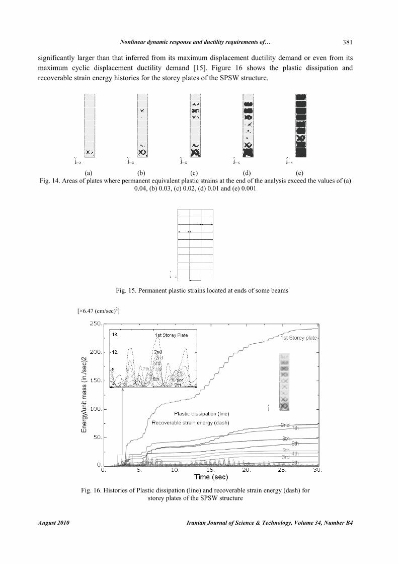
Figure 14 illustrates areas of the SPSW storey plates where permanent equivalent plastic strains at the end of the analysis exceed the values of 0.04, 0.03, 0.02, 0.01 and 0.001. This figure reveals that, as expected, a large area of each plate or whole experiences significant plastic strains. In spite of the fact that all the plate shear forces obtained by the analysis are greater than the corresponding design shear strengths (Fig. 13b), there are areas of some plates that are not yielded or experience only small values of plastic strains. This observation can also be explained by the reasons described previously.
Locations of permanent plastic strains in the beams and columns are shown in Fig. 15. As seen, the columns and VBEs experience no plastic strains, as required by AICS 341-05 [3], and plastic strains are induced at the ends of some beams.
d) Energy dissipation demands
Hysteretic energy )( pE is a measure of the inelastic energy dissipation demanded by the earthquake
ground motions [15-17]. Hysteretic energy includes cumulative effects of repeated cycles of inelastic response and, therefore, the effects of earthquake duration are included in this quantity [18]. Because of the numerous cycles of reversed yielding, the total hysteretic energy dissipated by a system can be
Nonlinear dynamic response and ductility requirements of…
August 2010 Iranian Journal of Science & Technology, Volume 34, Number B4
381
significantly larger than that inferred from its maximum displacement ductility demand or even from its maximum cyclic displacement ductility demand [15]. Figure 16 shows the plastic dissipation and recoverable strain energy histories for the storey plates of the SPSW structure.
(a) (b) (c) (d) (e) Fig. 14. Areas of plates where permanent equivalent plastic strains at the end of the analysis exceed the values of (a)
0.04, (b) 0.03, (c) 0.02, (d) 0.01 and (e) 0.001
Fig. 15. Permanent plastic strains located at ends of some beams
Fig. 16. Histories of Plastic dissipation (line) and recoverable strain energy (dash) for
storey plates of the SPSW structure
[×6.47 (cm/sec)2]

P. Memarzadeh et al.
Iranian Journal of Science & Technology, Volume 34, Number B4 August 2010
382
e) Energy ductility demands
There are many definitions available in the literature concerned with ductility such as maximum displacement ductility, cyclic displacement ductility, permanent displacement ductility and energy dissipation ductility [15, 19]. Sabouri-Ghomi and Gholhaki [20] conducted some experimental tests to investigate the displacement ductility of SPSWs according to ATC-24 protocol [21], and Popov’s definitions [22] resulted in ductility ratios of about 6.5 and 13, respectively.
The hysteretic energy ductility is an important quantity, as it contributes significant damage to the structure. A conventional definition for energy ductility, )( alConventioneμ , is as shown below [15]:
1)( +=y
palConventione E
Eμ (3)
in which pE and yE are the hysteretic energy and the energy at the yield state, respectively. There are also some other definitions for energy ductility in the literature on the basis of the above basic definition [23, 24].
The conventional definition of energy ductility is easy to use to evaluate the ductility demand of a monotonic SDOF system. In the case of a MDOF system, the determination of the yield state may be a challenge. In particular, for SPSWs, the problem is more significant as yielding of the web material of SPSW progress gradually in the web plate area and may be continued to obtain the full plastic capacity of the web plate. There are various definitions for the yield state of a MDOF system. Some researchers considered the yield state corresponding to the first yielding or to the intersection of the elastic line with the horizontal line at maximum loading [23], and/or also to 75% of ultimate loading [25]. However, it seems that there is not a common idea in this regard.
In the case of a cyclic MDOF system, the application of the conventional definition of energy ductility would be more complex. Some researchers assume the ductility of such a system equal to the ductility of a monotonic system whose response is the same as the maximum response envelope of the cyclic system [20]. However, as known, the energy ductility is a cumulative quantity and the mentioned assumption may be non-acceptable to the cyclic or dynamic systems. In addition, by this simplicity, the frequency characteristics of the response of such systems would be neglected.
This paper proposes a new definition for the energy ductility, ,eμ which is convenient to use in the case of dynamic response of SPSWs as follows:
( )
( )p s
es
max E Emax E
μ+
= (4)
where pE and sE are the hysteretic and recoverable strain energy, respectively, as defined previously.
Equation (4) has been inspired by the basic equation (Eq. 3) and describes a generalized definition of the energy ductility. The new definition (Eq. 4) is structurally very similar to the conventional definition and, in the case of the monotonic SDOF system, is simplified to that (Eq. (3)). Also, the proposed energy ductility factor, ,eμ is numerically equal to the displacement ductility of a monotonic SDOF system that dissipates the same energy [15]. Following a dynamic solution, Eq. (4) can be numerically calculated and results in a unique value for a typical case of SPSW.
Figure 16 gives a comparison between the plastic dissipation (hysteretic energy) and the recoverable strain energy for the storey plates of the SPSW structure.
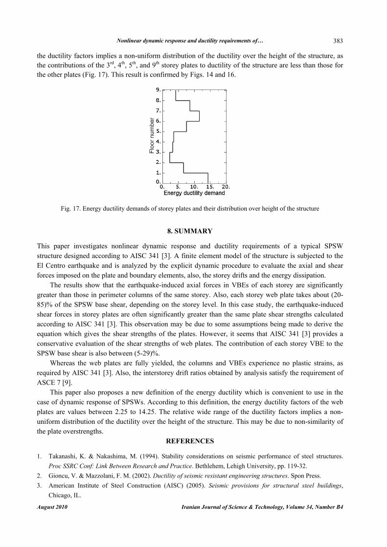
According to Eq. (4), the energy ductility demands for the storey plates of the SPSW structure and their distribution over the height of the structure are shown in Fig. 17. This figure shows that the energy ductility demands of the storey plates are in a range between 2.25 and 14.25. The relative wide range of
Nonlinear dynamic response and ductility requirements of…
August 2010 Iranian Journal of Science & Technology, Volume 34, Number B4
383
the ductility factors implies a non-uniform distribution of the ductility over the height of the structure, as the contributions of the 3rd, 4th, 5th, and 9th storey plates to ductility of the structure are less than those for the other plates (Fig. 17). This result is confirmed by Figs. 14 and 16.
Fig. 17. Energy ductility demands of storey plates and their distribution over height of the structure
8. SUMMARY
This paper investigates nonlinear dynamic response and ductility requirements of a typical SPSW structure designed according to AISC 341 [3]. A finite element model of the structure is subjected to the El Centro earthquake and is analyzed by the explicit dynamic procedure to evaluate the axial and shear forces imposed on the plate and boundary elements, also, the storey drifts and the energy dissipation.
The results show that the earthquake-induced axial forces in VBEs of each storey are significantly greater than those in perimeter columns of the same storey. Also, each storey web plate takes about (20-85)% of the SPSW base shear, depending on the storey level. In this case study, the earthquake-induced shear forces in storey plates are often significantly greater than the same plate shear strengths calculated according to AISC 341 [3]. This observation may be due to some assumptions being made to derive the equation which gives the shear strengths of the plates. However, it seems that AISC 341 [3] provides a conservative evaluation of the shear strengths of web plates. The contribution of each storey VBE to the SPSW base shear is also between (5-29)%.
Whereas the web plates are fully yielded, the columns and VBEs experience no plastic strains, as required by AISC 341 [3]. Also, the interstorey drift ratios obtained by analysis satisfy the requirement of ASCE 7 [9].
This paper also proposes a new definition of the energy ductility which is convenient to use in the case of dynamic response of SPSWs. According to this definition, the energy ductility factors of the web plates are values between 2.25 to 14.25. The relative wide range of the ductility factors implies a non-uniform distribution of the ductility over the height of the structure. This may be due to non-similarity of the plate overstrengths.
REFERENCES 1. Takanashi, K. & Nakashima, M. (1994). Stability considerations on seismic performance of steel structures.
Proc SSRC Conf: Link Between Research and Practice. Bethlehem, Lehigh University, pp. 119-32. 2. Gioncu, V. & Mazzolani, F. M. (2002). Ductility of seismic resistant engineering structures. Spon Press. 3. American Institute of Steel Construction (AISC) (2005). Seismic provisions for structural steel buildings,
Chicago, IL.

P. Memarzadeh et al.
Iranian Journal of Science & Technology, Volume 34, Number B4 August 2010
384
4. Sabelli, R. & Bruneau, M. (2007). Steel plate shear wall, AISC Steel Design Guide 20. USA. 5. Berman, J. W. & Bruneau, M. (2003). Plastic analysis and design of steel plate shear walls. J. Struct. Eng.
ASCE, Vol. 129, No. 11, pp. 1448-56. 6. American Institute of Steel Construction (AISC) (2005). Specification for structural steel buildings. Chicago, IL. 7. Kaltakci, M. Y., Koken, A. & Korkmaz, H. H. (2008). An experimental study on the behavior of infilled steel
frames under reversed-cycling loading. Iranian Journal of Science & Technology, Transaction B: Engineering, Vol. 32, No. B2, pp 157-160.
8. Hibbitt, Karlsson & Sorensen, Inc (HKS) (2007). ABAQUS Theory Manual (v6.7). Hibbitt, Karlsson, Sorensen, Inc of Pawtucket, Rhode Island.
9. American Society for Civil Engineers (ASCE) (2005). Minimum design loads for buildings and other structures (including Supplement No. 1), Reston, VA.
10. Hibbitt, Karlsson, Sorensen, Inc (HKS) (2007). ABAQUS Analysis user's manual (v 6.7), Hibbitt, Karlsson, Sorensen, Inc of Pawtucket, Rhode Island.
11. Behbahanifard, M. R., Grondin, G. Y. & Elwi, A. E. (2004). Analysis of steel plate shear wall using explicit finite element method. Proc., 13th World Conf. Earthq. Eng., Paper no. 2420, Vancouver, B.C., Canada.
12. Rezai, M. (1999). Seismic behavior of steel plate shear walls by shake table testing, PhD Thesis, Department of Civil Engineering, University of British Columbia, Canada.
13. Benson, D. J. (1992). Computational methods in Lagrangian and Eulerian hydrocodes. Comp. Meth. Appl. Mech. Eng., Vol. 99, pp. 235-394.
14. Oppenheim, A. V., Willsky, A. S. & Young, I. T. (1983). Signals and systems. Prentice-Hall Signal Processing Series. USA.
15. Mahin, S. A. & Bertero, V. V. (1981). An evaluation of inelastic seismic design spectra. J. Struct. Div. ASCE, 107(ST9), pp. 1777- 95.
16. Uang, C. M. & Bertero, V. V. (1990). Evaluation of seismic energy in structures. Earthq. Eng. Struct. Dyn., Vol. 19, 77-90.
17. Bertero, V. V., Uang, C. M. (1992). Issues and future directions in the use of an energy approach for seismic resistant design of structures. In: P. Fajfar and H. Krawinkler (eds), Nonlinear seismic analysis and design of reinforced concrete buildings, pp. 3-22.
18. Bozorgnia, Y. & Bertero, V. V. (2002). Improved damage parameters for post-earthquake application. Proc., SMIP02 Seminar on Utilization of Strong-Motion Data. Los Angeles, California.
19. Mahin, S. A. & Bertero, V. V. (1976). Problems in establishing and predicting ductility in aseismic design. Proc., Int. Symp. on Earthq. Struct. Eng., St. Louis, MO, pp. 613-628.
20. Sabouri-Ghomi, S. & Gholhaki, M. (2008). Ductility of thin steel plate shear walls. Asian J. Civil Eng. (Building and Housing), Vol. 9, No. 2, pp. 153-66.
21. Applied Technology Council. ATC-24 (1992). Guidelines for cyclic seismic testing of components of steel structures, California.
22. Popov, E. P. (1980). Seismic behavior of structural sub-assemblages. J. Struct. Div. ASCE, Vol. 106, pp. 1451-74.
23. Vayas, I. & Spiliopoulos, A. (1999). Ductility and overstrength of moment frames. Proc., 6th Int. Colloquium on Stability and Ductility of Steel Structure. September 9-11, Romania.
24. Naaman, A. E. & Jeong, S. E. (1995). Structural ductility of concrete beams prestressed with FRP tendons. Proc., 2nd Int. RILEM Symp.: Non-Metallic (FRP) for Concrete Structure., Ghent, Belgium, pp. 379-86.
25. Spadea, G., Bencardino, F. & Swamy, R. N. (1997). Strengthening and upgrading structures with bonded CFRP sheets design aspects for structural integrity. Proc., 3rd Int RILEM Symp: Non-Metallic (FRP) for Concrete Structures. Sapporo, Japan, pp. 379-86.