Non-traditional Machining...
22
Non-traditional Machining Processes ME 355, Introduction to Manufacturing Processes
Transcript of Non-traditional Machining...

Non-traditional
Machining Processes
ME 355, Introduction to
Manufacturing Processes

Outline
• Abrasive Grinding
• Non-traditional Machining Processes– Ultrasonic Machining
– Abrasive Water Jet Machining
– Chemical Machining
– Electro-chemical Machining
– Electro-chemical Grinding
– Electrodischarge Machining
– Laser Beam Machining
– Case Studies
– Overall Process comparisons

Grinding

Abrasive Grinding
• Can be viewed as
multiple very small
cutting edges
• Results in a very fine
finish
• Can leave residual
stresses
• Slow, small material
removal rates
• Sparking out

Standard Grinding Wheel
Designation
• While this is specific to grinding, realize that there are
similar standard designations in most industries
• Take the time to learn the standard designations early so
that you can speak intelligibly with those within the
industry.

Ultrasonic
Machining
• Ultrasonic vibration (20,000 Hz) of very small amplitudes (0.04-0.08 mm) drive the form tool (sonotrode) of ductile material (usually soft steel)
• An abrasive slurry is flowed through the work area
• The workpiece is brittle in nature (i.e. glass)
• The workpiece is gradually eroded away.
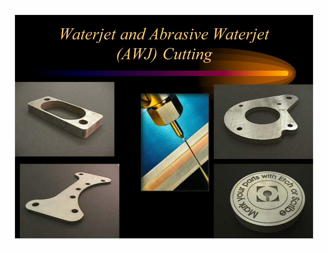
Waterjet and Abrasive Waterjet
(AWJ) Cutting

Abrasive
Waterjet and
Waterjet
examples

Abrasive
Water Jet• High pressure water (20,000-60,000 psi)
• Educt abrasive into stream
• Can cut extremely thick parts (5-10 inches possible)
– Thickness achievable is a function of speed
– Twice as thick will take more than twice as long
• Tight tolerances achievable
– Current machines 0.002” (older machines much less capable ~ 0.010”
• Jet will lag machine position, so controls must plan for it
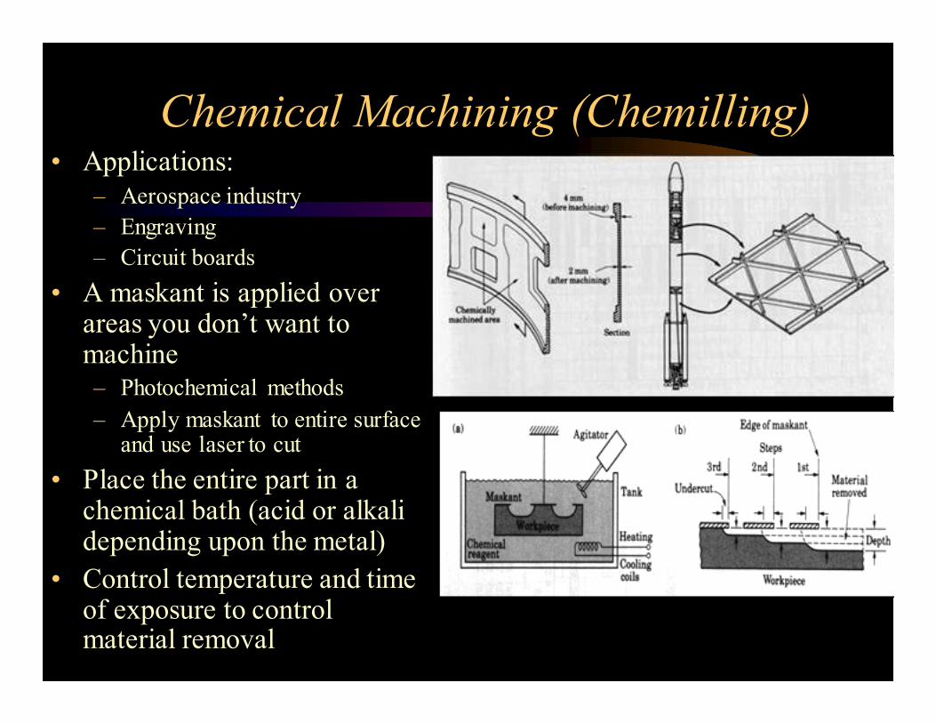
Chemical Machining (Chemilling)• Applications:
– Aerospace industry
– Engraving
– Circuit boards
• A maskant is applied over areas you don’t want to machine– Photochemical methods
– Apply maskant to entire surface and use laser to cut
• Place the entire part in a chemical bath (acid or alkali depending upon the metal)
• Control temperature and time of exposure to control material removal

Electro-Chemical
Machining (ECM)• Works on the principle of electrolysis – accelerated chemilling
• Die is progressively lowered into workpiece as workpiece is dissociated into ions by electrolysis
• Electrolytic fluid flows around workpiece to remove ions and maintain electrical current path
• Low DC voltage, very High current (700 amps)
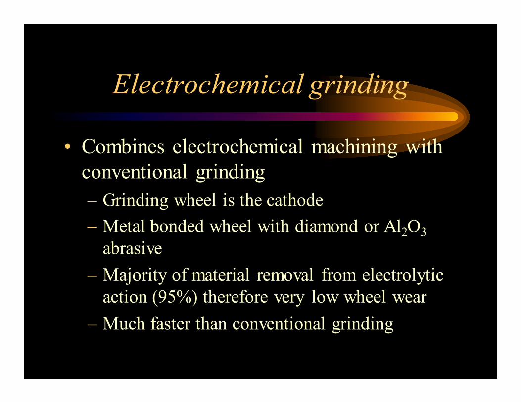
Electrochemical grinding
• Combines electrochemical machining with
conventional grinding
– Grinding wheel is the cathode
– Metal bonded wheel with diamond or Al2O3abrasive
– Majority of material removal from electrolytic
action (95%) therefore very low wheel wear
– Much faster than conventional grinding

Electrode Discharge
Machining (EDM)• Direct Competitor of ECM – much more common than ECM
• The tool acts as a cathode (typically graphite) is immersed in a Dielectric fluid with conductive workpiece
• DC voltage (~300V) is applied. As voltage builds up over gap between workpiece and tool, eventually you get dielectric breakdown (sparking at around 12,000 deg F)
• The sparking erodes the workpiece in the shape of the tool
• The tool is progressively lowered by CNC as the workpiece erodes
• Cycle is repeated at 200,000-500,000 Hz
• Dielectric:
– Cools tool and workpiece
– Flushes out debris from work area

Die Sinker
vs. Wire
EDM• Die sinker EDM
– The die sinks into the part
as it sparks away the
workpiece
– Most common Injection
molding die process
• Wire EDM
– The electrode is a wire that
traverses through the part
– Common for Extrusion
Dies

Laser Beam Machining
• Lasers are high intensity focused light sources
– CO2• Most widely used
• Generally more powerful that YAG lasers
• Cutting operations commonly
– Nd:YAG (Neodymium ions in an Yttrium Aluminum Garnet)• Less powerful
• Etching/marking type operations more commonly
• Limited in depth of cut (focus of light)
• Would limit workpiece to less than 1 inch (< ½” typically)
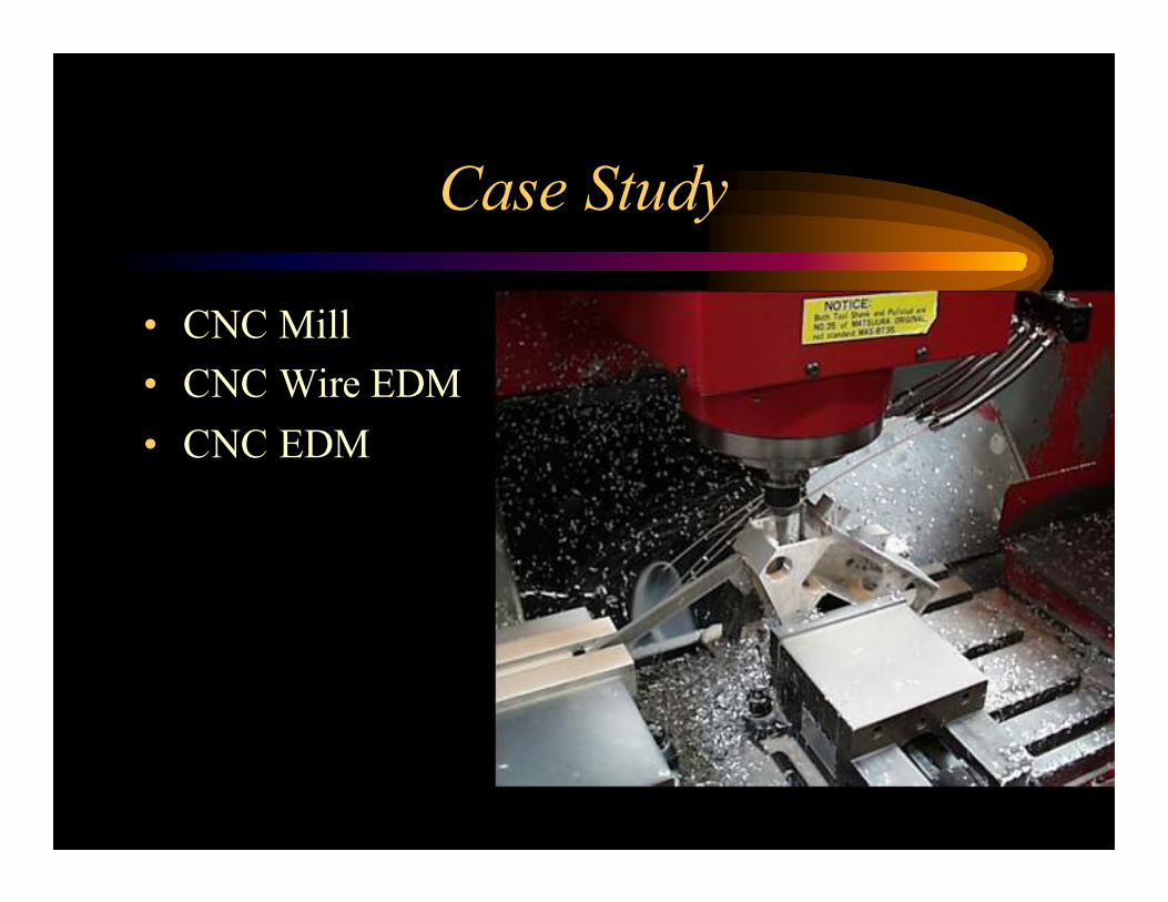
Case Study
• CNC Mill
• CNC Wire EDM
• CNC EDM

Wire EDM (not shown), Die Sinker
EDM, Anodized
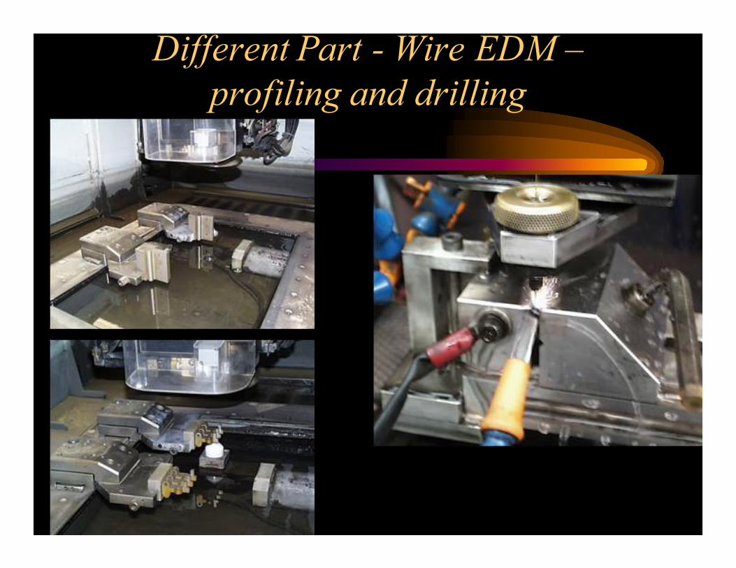
Different Part - Wire EDM –
profiling and drilling

Case Study Three
1. CNC Milling 2. Setup on wire EDM
3. QA After wire EDM 4. Grinding a face on the part
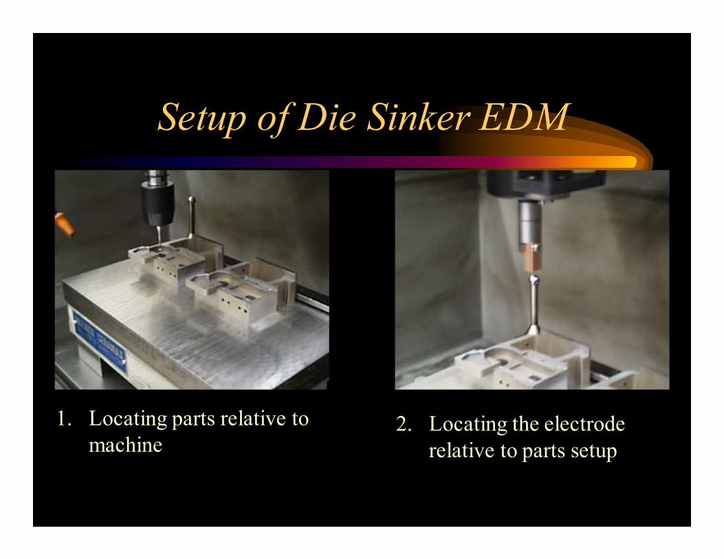
Setup of Die Sinker EDM
1. Locating parts relative to
machine2. Locating the electrode
relative to parts setup
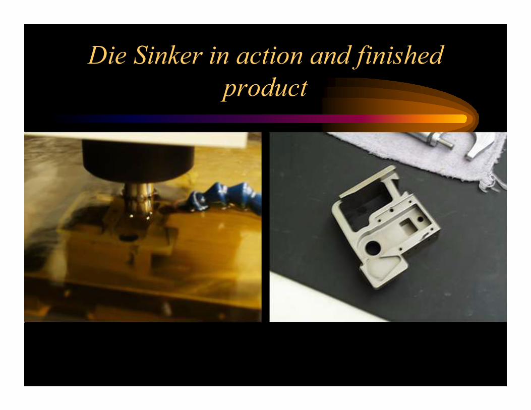
Die Sinker in action and finished
product

Overall Machining Tolerances and Surface Roughness