Non-Q Design Analysis Cover Sheet CRWMS/M&O QA: N/A
26
CRWMS/M&O @ Non-Q Design Analysis Cover Sheet Complete only applicable items. QA: N/A Page: 1 BAB000000-0 17 17-0200-00005 5. TOTAL ATTACHMENTS Of: 26 REV 00 26 6. ATTACHMENT NUMBERS - NO. OF PAGES IN EACH 2. DESIGN ANALYSIS TITLE MOL.19990712.0183 14. TOTAL P AGT CONCRETE SUPPORT DESIGN FOR MISCELLANEOUS ESF UTILITIES 3. DOCUMENT IDENTIFIER (Including Rev. No.) 0 7. Originator ~~~ 8. Checker 9. Lead Design Engineer ~~ 10. Department Manager I 1. Remarks NIA Printed Name Signature Thomas A. Misiak . 1 I K. J. Herold I V M. E. Taylor, Jr. / N. R. Kennedy Date PRO-TS-004 Effective 12/14/981 0642 IRev. 09/17/981
Transcript of Non-Q Design Analysis Cover Sheet CRWMS/M&O QA: N/A

CRWMS/M&O @ Non-Q Design Analysis Cover Sheet
Complete only applicable items. QA: N/A
Page: 1
BAB000000-0 17 17-0200-00005 5. TOTAL ATTACHMENTS
Of: 26
REV 00 26 6. ATTACHMENT NUMBERS - NO. OF PAGES IN EACH
2. DESIGN ANALYSIS TITLE MOL.19990712.0183
14. TOTAL P A G T
CONCRETE SUPPORT DESIGN FOR MISCELLANEOUS ESF UTILITIES 3. DOCUMENT IDENTIFIER (Including Rev. No.)
0
7. Originator
~~~
8. Checker
9. Lead Design Engineer
~~
10. Department Manager
I 1. Remarks
NIA
Printed Name Signature
Thomas A. Misiak .
1 I
K. J. Herold
I V
M. E. Taylor, Jr.
/
N. R. Kennedy
Date
PRO-TS-004 Effect ive 12/14/981 0642 IRev. 09/17/981

CRWMS/M&O
4. Revision NO.
Non-Q Design Analysis Revision Record
5. Description of Revision
Complete only applicable items.
00
PRO.TS.004 IElfsctws 121141981
Initial Issue
0624 IRsv. 0911719

Title: CONCRETE SUPPORT DESIGN FOR MISCELLANEOUS ESF UTILITIES Document Identifier: BAB000000-0 17 17-0200-00005 REV 00 Page: 3 of26
1. PURPOSE
The purpose and objective of this analysis is to design concrete supports for the miscellaneous utility equipment used at the Exploratory Studies Facility (ESF). Two utility systems are analyzed: (1) the surface collection tanks of the Waste Water System, and (2) the chemical tracer mixing and storage tanks of the Non-Potable Water System.
This analysis satisfies design recommended in the Title 111 Evaluation Reports for the Subsurface Fire Water System and Subsurface Portion of the Non-Potable Water System (CRWMS M&O 1998a) and Waste Water Systems (CRWMS M&O 1998b).
This analysis does not constitute a level-3 deliverable, a level-4 milestone, or a supporting work product. This document is not being prepared in support of the Site Recommendation, Environmental Impact Statement (EIS), or Monitored Geologic Repository (MGR) License Application (LA) and should not be cited as a reference in the Site Recommendation, EIS, or MGR LA.
2. QUALITY ASSURANCE
No Quality Assurance (QA) Controls are applicable to the items or activities addressed in this design analysis. The items addressed in this analysis are temporary and therefore have not been classified in accordance with QAp-2-3. There are no Determination of Importance Evaluations (DIE) Controls associated with the concrete supports covered in this analysis (CRWMS M&O 1999). A QAP-2-0 evaluation has been completed (Activity Title: JN 2Y5898 DEFERRED - 126D2465MA - Additional Designs per TER's) and determined to not be subject to the U.S. Department of Energy (DOE), Office of Civilian Radioactive Waste Management, DOE/RW-O333P, Quality Assurance Requirements and Description for the Civilian Radioactive Waste Management Program. QA:N/A.
3. METHOD
The analytical method is used.
4. DESIGN INPUTS
4.1 DESIGN PARAMETERS
4.1.1 Maximum allowable soil bearing pressure (p) = 5000 psf with 1 inch total settlement (Sections 7.2.2, 7.2.3, 7.2.4, 7.3.2 & 7.3.3) (Riggins 1995 Pages 4 & 5 )
4.1.2 Concrete compressive strength (fc') = 4000 psi (Sections 7.2.2, 7.2.3, 7.3.2 & 7.3.3) (CRWMS M&O 1995a Section 2.01)

Title: CONCRETE SUPPORT DESIGN FOR MISCELLANEOUS ESF UTILITIES Document Identifier: BAB000000-0 171 7-0200-00005 REV 00
~ Page: 4 of 26
4.2
4.1.3
4.1.4
4.1.5
4.1.6
4.1.7
4.1.8
4.1.9
Seismic criterion = 0.3 g for temporary surface facilities (consistent with Zone 3 of the Uniform Building Code (UBC) (ICBO 1997)) (Sections 4.2.1, 4.2.4, 7.1, 7.2.2, 7.2.3, 7.2.4, 7.3.2 & 7.3.3) (YMP 1997 Appendix A)
Design wind speed = 75 mph (Sections 4.2.2, 7.1, 7.2.4 & 7.3.3) (YMP 1997 Section 3.2.1.2.1.l.C)
Weight of normal reinforced concrete = 12.5 lb/fi2/in * 12 in = 150 Ibs/fi3 (Sections 7.2.2, 7.2.3, 7.2.4, 7.3.2 & 7.3.3) (AISC 1995 Page 6-9)
Concrete reinforcement: ASTM A615 (ASTM 1996) Grade 60 (Sections 7.2.2, 7.2.3, 7.3.2 & 7.3.3) (CRWMS M&O 1995a Section 2.05)
Anchor bolts: ASTM A307 (ASTM 1997a) (Sections 7.2.4 & 7.3.3) (CRWMS M&O 1995b Section 2.01E. 1)
Structural steel: ASTM A36 (ASTM 1997b) (Sections 7.2.4 & 7.3.3) ,(CRWMS M&O 1995b Section 2.01B)
Weld metal electrodes: E70XX (Sections 7.2.4 & 7.3.3) (AWS 1998 Table 3.1)
CRITERIA
The following criteria were developed to respond to the requirements presented in the Exploratory Studies Facility Design Requirements (ESFDR) (YMP 1997) that specifically apply to this analysis. The applicable requirements are cited for each statement.
4.2.1
4.2.2
4.2.3
Earthquake design parameters for surface facilities shall be calculated in accordance with the information in Appendix A (YMP 1997 Section 3 2.1 2.1.1 .B). The concrete supports are designed to withstand the 0.3 g seismic event specified for temporary surface facilities in Appendix A and consistent with Zone 3 of the UBC (ICBO 1997) (Sections 4.1.3 & 7.1).
The ESF surface facilities shall be designed to withstand 75 mph (high winds) prevailing winds with maximum gusts up to 97 mph (YMP 1997 Section 3.2.1.2.1.1 .C). The supports are designed to withstand wind loads generated on the tanks in accordance with the UBC (ICBO 1997) using a design wind speed of 75 mph (Sections 4.1.4 & 7.1).
The ESF non-permanent items shall be designed for a 25-year maintainable service life (YMP 1997 Section 3.2.1.2.2.A). The supports are composed of steel reinforced concrete and will be monitored through the Operation and Maintenance (O&M) phase of the ESF (Section 7.1).

Title: CONCRETE SUPPORT DESIGN FOR MISCELLANEOUS ESF UTILITIES Document Identifier: BAB000000-0 17 17-0200-00005 REV 00 Page: 5 of26
4.2.4 The ESF shall be designed in compliance with the applicable requirements in the Uniform Building Code (YMP 1997 Section 3.2.1.2.4.A). The concrete supports are designed to withstand a 0.3 g seismic event consistent with Zone 3 of the UBC (ICBO 1997) and follow the wind design approach stipulated in the UBC (Sections 4.1.3 & 7.1).
4.2.5 The ESF shall'be designed in compliance with the applicable requirements contained in ACI 318 Building Code Requirements for Reinforced Concrete Code (YMI? 1997 Section 3.2.1.2.4.B). The concrete supports are designed in accordance with ACI 3 18 (ACI 1995) (Section 7.1).
4.3 ASSUMPTIONS
Not Used
4.4 CODES AND STANDARDS
ACI (American Concrete Institute) 1995. Building Code Requirements for Structural Concrete (ACI 3I8-95) and Commentary (ACI 318R-95). ACI 3 1813 18R. Farmington Hills, Michigan: ACI. TIC: 233584.
AISC (American Institute of Steel Construction, Inc.) 1995. Manual of Steel Construction Allowable Stress Design Ninth Edition. MO16. Chicago, Illinois: AISC. TIC: 232994.
ASTM (American Society for Testing and Materials) 1996. Standard Speczfication for Deformed and Plain Billet-Steel Bars for Concrete Reinforcement. ASTM A61 5lA6 15M- 96a. West Conshohocken, Pennsylvania: ASTM. TIC: 243 52 1.
ASTM 1997a. Standard Specrfication for Carbon Steel Bolts and Stud, 60 000 PSI Tensile Strength. ASTM A307-97. West Conshohocken, Pennsylvania: ASTM. TIC: 243522.
ASTM 1997b. Standard Speclfication for Carbon Structural Steel. ASTM A36lA36M-97a. . West Conshohocken, Pennsylvania: ASTM. TIC: 243523.
American Welding Society (AWS) 1998. Structural Welding Code - Steel. ANSIIAWS D1.l-98. Miami, Florida: AWS. TIC: 236843.
ICBO (International Conference of Building Officials) 1997. Uniform Building Code, Volume 2, Structural Enpeering Design Provisions. 101L97. Wittier, California: ICBO. TIC: 233818.

Title: CONCRETE SUPPORT DESIGN FOR MISCELLANEOUS ESF UTILITIES Document Identifier: BAB000000-0 171 7-0200-00005 REV 00 Page: 6 of 26
5. REFERENCES
CRWMS M&O (Civilian Radioactive Waste Management System Management and Operating Contractor) 1995a. Cast-In-Place Concrete-Surface. BAB000000-01717-6300-03300 REV 02. Las Vegas, Nevada: CRWMS M&O. ACC: MOL. 199605 14.033 1.
CRWMS M&O 1995b. Structural Steel and Miscellaneous Metal. BABEAC000-01717-6300- 05121 REV 03. Las Vegas, Nevada: CRWMS M&O. ACC: MOL.19960523.0248.
CRWMS M&O 1998a. Title 111 Evaluation Report for the Subsurface Fire Water System and Subsurface Portion of the Non-Potable Water System. BA0000000-01717-5705-00004 REV 00. Las Vegas, Nevada: CRWMS M&O. ACC: MOL. 19981007.0042.
CRWMS M&O 1998b. Title 111 Evaluation Report for the Waste Water Systems. BA0000000- 01717-5705-00007 REV 01. Las Vegas, Nevada: CRWMS M&O. ACC: MOL.19981019.0150.
CRWMS M&O 1999. Determination of Importance Evaluation for the Surface Exploratory Studies Facility. BAB000000-0 17 17-2200-001 06 REV 03. Las Vegas, Nevada: CRWMS M&O. ACC: MOL. 19990329.0272.
MacGregor, J. G. 1997. G ; 2 22
Reinforced Concrete: Mechanics and Design 3rd Edition. TCRN . Upper Saddle River, New Jersey: Prentice Hall, Inc. TIC: 242587. -r*M 2 4 - 9 9
Riggins, M. 1995. Geotechnical Engineering Investigation for the Proposed Muck Conveyor Foundations at the ESF. Correspondence from M. Riggins to M. Taylor. April 18, 1995. ACC: MOL, 19950815.0024.
YMP (Yucca Mountain Project) 1997. Exploratory Studies Facility Design Requirements. YMl?/CM-0019, REV 02 ICN 01. Las Vegas, Nevada: Yucca Mountain Site Characterization Office. ACC: MOL. 19980107.0544, MOL. 19960926.0065.
6. USE OF COMPUTER SOFTWARE
Not Used
7. DESIGN ANALYSIS
7.1 INTRODUCTION
The as-constructed Waste Water System surface collection tanks and the Non-Potable Water System chemical mixing and storage tanks do not satisfjr seismic and wind criteria for the surface equipment (CRWMS M&O 1998b page 10 & CRWMS M&O 1998a page 12). To

Title: CONCRETE SUPPORT DESIGN FOR MISCELLANEOUS ESF UTILITIES Document Identifier: BAI3000000-0 17 17-0200-00005 REV 00 Page: 7 of 26
#1 7'6" #2 b
30' 34'
satis@ the seismic and wind criteria, the tanks will be anchored to steel reinforced concrete supports.
7'
The ESFDR currently specifies a 0.3 g seismic criterion for temporary surface facilities and consistent with Zone 3 of the UBC (4.1.3) and a 75 mph design wind speed (4.1.4). The supports are designed to withstand a 0.3 g seismic event (4.2.1 & 4.2.4) and wind loads generated on the tanks in accordance with the UBC using a design wind speed of 75 mph (4.2.2 & 4.2.4).
The steel reinforced concrete supports are temporary and can be monitored through the 25- year service life for cracking or other damage (4.2.3). The concrete supports are designed using the requirements stipulated in ACI 3 18 (ACI 1995) (4.2.5).
Due to a layer of oil that can be apparent on top of the waste water in Tank #1, the need to have secondary containment around the Waste Water tanks was discussed by the A/E, Site O&M, and Environmental Programs Department and determined to not be necessary.
7.2 WASTE WATER TANK SLAB DESIGN
7.2.1 Layout / Design Loads
The as-constructed Waste Water tank layout and dimensions have been measured by Title I11 and will be field verified:
I I
WASTE WATER TANKS LAYOUT PLAN
5'3"
W6x 15 each side
#2 (4) W6x9 stringers (TYP) under each side and along bottom
14'
2'
WASTE WATER TANKS ELEVATION

Title: CONCRETE SUPPORT DESIGN FOR MISCELLANEOUS ESF UTILITIES Document Identifier: BAl3000000-0 171 7-0200-00005 REV 00 Page: 8 of 26
The tanks are constructed from approximately 3/16 inch plate steel and are open at the top. To incorporate miscellaneous steel, the weights of the tanks are calculated using % inch plate. The slabs are designed to support the worst loading condition, i.e., completely full tanks. To account for the settlement of dissolved and/or suspended solids, the weight of water in Tank #1 will conservatively be increased by 10%.
Calculate tank loads: Tank #1: Volume of tank = (30)(7.5)(5.25) = 1181.25 A3 Weight of tank = [(2)(7.5)(5.25)+(2)(30)(5.25)+(30)(7.5)](% /12)(490 lbs/A3 (AISC 1995 page 6-8)) = 63 16 lbs Weight of water = (1181.25)(62.4 lbs/ft3) = 73710 lbs; w/ settlement increase = (1.1)(73710) = 81081 lbs Weight of W6x15 skid frame = [(2)(30)+(2)(7.5)](15) = 1125 lbs The weight of the filters can be neglected since it is minor in comparison to the weights of the tank and the water. Total weight = 6316 + 81081 + 1125 = 88522 lbs, say 88600 lbs = 88.6 kips Tank #2: Volume of tank = (34)(14)(7)+(20)(5)(7)+(2)(%)(7)(2)(7) = 4130 A3 Weight of tank = [(2)( 14)(7)+(2)(3)(7)+(2)(34)( 14)+(2)(20)(5)+(2)(2)(%)(2)(7) +(2)(7)(22+72)”+(20)(7)](% /12)(490 Ibs/ft3) = 16945 lbs Weight ofwater = (4130)(62.4 lbs/ft3) = 257712 lbs Weight of 10” pipes = (6)(7)(40.48 lbs/ft3 (AISC 1995 p. 1-93)) = 1700 lbs Weight of W6x9 stringers = (4)(9)[(2)(22+72)”+20+(2)(3)] = 1460 lbs Total weight = 16945 + 257712 + 1700 + 1460 = 277817 lbs, say 277900 lbs = 277.9
Tank #3 : Volume of tank = (~)(8/2)~(11.333) = 569.66 A3 Weight of tank = [(2)(~)(8/2)(11.333)+(~)(8/2)~](% /12)(490 lbs/ft3) = 3421 lbs Weight of water = (569.66)(62.4 lbs/ft3) = 35547 Ibs Total weight = 3421 + 35547 = 38968 Ibs, say 39000 lbs = 39.0 kips
kips
Two separate slabs will be designed, one for tanks #1 & #3 due to their proximity and one for tank #2 due to its size.
7.2.2 Slab Design: Tanks #1 & #3
Try 44’ x 12’ x 1’ slab:
12’
1‘
44’ I CONCRETE SLAB LAYOUT FOR TANKS #1& #3

Title: CONCRETE SUPPORT DESIGN FOR MISCELLANEOUS ESF UTILITIES Document Identifier: BAB000000-017 17-0200-00005 REV 00 Page: 9 of 26
Check bearing pressure on soil (load is transferred at 45" relative to thickness of slab): Tank #1 (design w/ each long side W6x15 skid taking ?h load): Bearing area on slab = AI = (30)(6"/12) = 15 R2/skid Bearing area on soil = A2 = (30+(2)(1))*(6/12+(2)(1)) = (32)(2.5) = 80 ft2/skid Weight of concrete = (80)( 1)( 150 lbs/ft3 (4.1.5)) = 12000 lbdskid D = Total dead load = 88600/2 + 12000 = 56300 lbs/skid E = Seismic load (4.1.3) = (.3)(56300) = 16890 lbdskid Conservatively calculate the bearing pressure on the soil using factored loads: U = Factored combination load = 0.75[1.4D + 1.7L + 1.7(1.1E)] (ACI 1995 Sections 9.2.2 & 9.2.3) = (.75)[(1.4)(56300)+(1.7)(1.1)(16890)] = 82803 lbs/skid qs = bearing pressure = U/A2 = 82803/80 = 1035 psf < p = 5000 psf (4.1.1) :. OK Tank #3 : Bearing .area on slab = AI = (7~)(8/2)~ = 50.3 R2
Weight of concrete = (78.54)( 1)( 150 lbs/ft3) = 1 178 1 lbs D = 39000 + 11781 = 50781 lbs E = (.3)(50781) = 15234 lbs U = (.75)[(1.4)(50781)+(1.7)(1.1)(15234)] = 74686 lbs qs = 74686/78.54 = 951 psf < p = 5000 psf :. OK
A2 = (7~)((8+(2)(1))/2)~ = ( 7 ~ ) ( 5 ) ~ = 78.54 R2
The 5000 psf maximum bearing pressure (4.1.1) is based on allowing a one inch settlement. For the tanks and their corresponding slabs, a one inch settlement is not considered excessive.
Check shear through concrete: Tank #1: D = 88.612 = 44.3 kips (ignore the dead weight of the slab as it will be subtracted from the net pressure in the calculation of the maximum shear) E = (.3)(44.3) = 13.3 kips Vu = Total factored shear load = (.75)[(1.4)(44.3)+(1.7)(1.1)(13.3)] = 65.2 kips Vu I @Vn = @(Vc+Vs) = 0.85VC (ACI 1995 Sections 1 1.1.1 & 9.3.2.3) V, = (2+4/P,)(f,')'bod < (4)(f,')'bod (ACI 1995 Section 11.12.2.1) f,' = 4000 psi (4.1.2) d = distance from compression fiber to center of rebar = 12 - 3" cover (ACI 1995 Section 7.7.1) - % diameter of rebar, say ?h inch = 8.5 in bo = perimeter of critical section which occurs at a distance d/2 from shear area (ACI 1995 Section 11.12.1.2) = (2)[((30)(12)+(2)(8.5/2))+(6+(2)(8.5/2))] = 766 in pc = ratio long side to short side = 30/0.5 = 60 [2+4/60] = 2.067 < 4 :. use 2.067 $Vc = (.85)(2.067)(4000)"(766)(8.5)/1000 = 723.5 kips > Vu = 65.2 kips :. OK Tank #3 : D = 39.0 kips E = (.3)(39.0) = 11.7 kips Vu= (.75)[(1.4)(39.0)+(1.7)(1.1)(11.7)] = 57.4 kips

Title: CONCRETE SUPPORT DESIGN FOR MISCELLANEOUS ESF UTILITIES Document Identifier: BAB000000-0 171 7-0200-00005 REV 00 Page: 10 of 26
bo = (n)[(8)(12)+(2)(8.5/2)] = 328.3 in
[2+4/1] = 6 > 4 :. use 4 $Vc = (.85)(4)(4000)"(328.3)(8.5)/1000 = 600.1 kips > Vu = 57.4 kips :. OK
p c = 1
Check bearing on concrete: Tank #1: Max bearing < $(0.85fc'A1) (ACI 1995 Section 10.17.1) (b for bearing = 0.7 (ACI 1995 Section 9.3.2.4) Max bearing = (.7)(.85)(4)(15*12*12) = 5141 kips > P, = Vu = 65.2 kips :. OK Tank #3: Max bearing = (.7)(.85)(4)(50.3*12*12) = 17239 kips > P, = Vu = 57.4 kips :. OK
Calculate Mu (using 1' section across short side of slab): P U ( U P41)
or
0 Tank #1: Pu(l) = 65.2 kips which creates a pressure (p,) on the soil = P,/A2 = 65200/80 = 815 lb/ft2 The dead weight of the slab can be ignored as it will be subtracted from the net pressure in the calculation of the maximum moment. CM at end = 0: (0)(12)~/2 = (815)(2.5)[(2.25+3/12)+(2.25+7.5-3/12)] :. o = 339.6 lb/ft Mmx at end of slab = oL2/2 (AISC 1995 page 2-302) = (339.6)(2.25)2/2 = 860 lb-ft Mmx between skids = oL2/8 (AISC 1995 page 2-296) = (339.6)(7)2/8 = 2080 lb-R (top reinforcement) Tank #3 : Pu(3) = 57.4 kips which creates a pressure (p,,) on the soil = PdA2 = 57400178.54 = 731 lb/ft2 CM at end = 0: (0)(12)~/2 = (731)(10)(6) :. o = 609.2 Ib/R Mmax at end of slab = (609.2)(2)2/2 = 1218.4 lb-ft > 860 lb-ft :. Mu = 1218.4 lb-ft (bottom reinforcement)
#Design reinforcement using A61 5 (ASTM 1996) Grade 60 rebar (4.1.6): Bottom bars: A, = Mu/(bfyjd (MacGregor 1997 Page 123) j E 0.925 for slabs (MacGregor 1997 Page 123) 4 = 0.9 (ACI 1995 Section 9.3.2.1) A, = (1218.4*12)/(.9)(60000)(.925)(8.5) = 0.03 in2&
= 0.0018bh (ACI 1995,Section 7.12.2.1) = (.0018)(12)(12) = 0.26 in2/ft

Title: CONCRETE SUPPORT DESIGN FOR MISCELLANEOUS ESF UTILITIES Document Identifier: BAB000000-0 17 17-0200-00005 REV 00 Page: 11 of26
(% bottom bars & % top bars) = .26/2 = 0.13 in2/A > 0.03 in2/ft :. controls Using a spacing of 12” and #4 bars, A, = 0.20 in2/ft (ACI 1995 Appendix E) > 0.13 in2/ft :. OK Top bars: Conservatively calculate A, using same d (actual d increases due to minimum cover requirement decreasing per ACI 1995 Section 7.7.1): A, = (2080*12)/(.9)(60000)(.925)(8.5) = 0.06 in2& < A,(~,,) = 0.13 in2/ft. Using a spacing of 12‘’ and #4 bars, A, = 0.20 in2/ft > 0.13 in2& :. OK
Calculate Mu (using 1’ section across long side of slab):
0
CM at end = 0: (0)(44)~/2 = (731)(10)(6)+(815)(32)(27) :. o = 773 lb/ft Mm,, at end of slab = (773)(2)2/2 = 1546 lb-ft Comparing the maximum moment with the maximum moment across the short side of the slab, by inspection A, top and bottom will be controlled by A,(-) = 0.13 in2/ft. Using a spacing of 12” and #4 bars, A, = 0.20 in2/ft > 0.13 in2/ft :. OK
-
Use a 44’ x 12’ x 1‘ concrete slab with #4 A61 5 (ASTM 1996) Grade 60 rebar on 12” centers each way top and bottom for tanks #1 & #3.
7.2.3 Slab Design: Tank #2
I Try 24‘ x 1 1’ x 1’6‘’ slab:
#2
I I t I t I I I I I I I I I
11’
24’
CONCRETE SLAB LAYOUT FOR TANK #2
Check bearing pressure on soil (load is transferred at 45” relative to thickness of slab): Design with load distributed between centers of outer pipes: P (unf‘actored) = 277.9 kips / 6 pipes = 46.32 kips/pipe ,*,

Title: CONCRETE SUPPORT DESIGN FOR MISCELLANEOUS ESF UTILITIES Document Identifier: BAB000000-017 17-0200-00005 REV 00 Page: 12 of 26
Bearing area on slab = AI = (20”/12)(7’) = 11.67 fi2 Bearing area on soil = A2 = (20+(2)(18))/12*(7+(2)(18/12)) = (4.67)(10) = 46.7 fi2 Weight of concrete = (46.7)(18/12)(150 lbs/fi3 (4.1.5))/1000 = 10.5 kips D = Total dead load = (3)(46.32)+10.5 = 149.5 kips E = Seismic load (4.1.3) = (.3)(149.5) = 44.85 kips Conservatively calculate the bearing pressure on the soil using factored loads: U = Factored combination load = 0.75[ 1.4D + 1.7L + 1.7( 1. lE)] (ACI 1995 Sections 9.2.2 & 9.2.3) = (.75)[(1.4)(149.5)+(1.7)(1.1)(44.85)] = 219.9 kips qs = bearing pressure = U/A2 = 219.9” 1000/46.7 = 4709 psf < p = 5000 psf (4.1 .l) :. OK
Check shear through concrete: D = (3)(46.32) = 139 kips (ignore the dead weight of the slab as it will be subtracted from the net pressure in the calculation of the maximum shear) E = (.3)(139) = 41.7 kips Vu = Total factored shear load = (.75)[(1.4)(139)+(1.7)(1.1)(41.7)] = 204.4 kips Vu I @V,, = @(Vc+V,) = 0.85Vc (ACI 1995 Sections 11.1.1 & 9.3.2.3) V, = (2+4/Pc)(E’)”bod < (4)(fc‘)”bod (ACI 1995 Section 1 1.12.2.1) f,‘ = 4000 psi (4.1.2) d = distance from compression fiber to rebar = 18 - 3” cover (ACI 1995 Section 7.7.1) - ’/2 diameter of rebar, say ‘/2 inch = 14.5 in bo = perimeter of critical section which occurs at a distance d/2 from shear area (ACI 1995 Section 11.12.1.2) = (2)[((20)+(2)(14.5/2))+((7)(12)+(2)(14.5/2))] = 266 in P, = ratio long side to short side = 7/(20/12) = 4.2 [2+4/4.2] = 2.95 < 4 :. use 2.95 +Vc = (.85)(2.95)(4000)”(266)(14.5)/1000 = 61 1.7 kips > Vu = 204.4 kips :. OK
Check bearing on concrete: Max bearing < @(O.85fc‘A1) (ACI 1995 Section 10.17.1) @ for bearing = 0.7 (ACI 1995 Section 9.3.2.4) Max bearing = (.7)(.85)(4)(11.67*12*12) = 4000 kips > P, = Vu = 204.4 kips :. OK
Calculate Mu (using 1’ section across long side of slab): P U P U
I I I ! + I I 1 + 1
I \ I \
t t t t t . t t t t t t t t t t t t t t 0
P, = 204.4 kips which creates a pressure (p,) on the soil = P,/Ai = 204.4/46.7 = 4.38
The dead weight of the slab can be ignored as it will be subtracted from the net pressure in the calculation of the maximum moment. CM at end = 0: (o)(24)*/2 = (4.38)(4.67)(3.25+20.75) :. o = 1.7 kip/&
kip/fi2

Title: CONCRETE SUPPORT DESIGN FOR MISCELLANEOUS ESF UTILITIES Document Identifier: BAB000000-0 17 17-0200-00005 REV 00 Page: 13 of 26
Mm,, at end of slab = oL2/2 (AISC 1995 page 2-302) = (1.7)(2.42)2/2 = 4.98 kip-ft M,, between spans = oL2/8 (AISC 1995 page 2-296) = (1 .7)(15.83)2/8 = 53.3 kip-ft
Design reinforcement using A615 (ASTM 1996) Grade 60 rebar (4.1.6): Bottom bars: A, = Mu/$fyjd (MacGregor 1997 page 123) j E 0.925 for slabs (MacGregor 1997 page 123) 4 = 0.9 (ACI 1995 Section 9.3.2.1) A, = (4.98*12)/(.9)(60)(.925)(14.5) = 0.08 in2/& A,(min) = 0.0018bh (ACI 1995 Section 7.12.2.1) = (.0018)(12)(18) = 0.39 in2/ft A,fmin) (!h bottom bars & $5 top bars) = .39/2 = 0.195 in2/fi > 0.08 in2/fi :. controls Using a spacing of 12" and #4 bars, A, = 0.20 in2/fi (ACI 1995 Appendix E) > 0.195 in2/fi :. OK Top bars (conservatively calculate using same d): A, = (53.3*12)/(.9)(60)(.925)(14.5) = 0.88 in2/fi > &(min) = 0.39 in2/A :. A, controls Using a spacing of 12" and #9 bars, A, = 1.00 in2/fi (ACI 1995 Appendix E) > 0.88 in2/ft :. OK
Calculate Mu (using 1' section across short side of slab): p u
+ I ! \ \ I .. t t t t 4 f f f f t t t t t +
0
CM at end = 0: (0)(11)~/2 = (4.38)(10)(5.5) :. o = 3.98 kip/R Mm,, at end of slab = oL2/2 = (3.98)(2)2/2 = 7.96 kip-fi
Design reinforcement: Bottom bars: A, = (7.96*12)/(.9)(60)(.925)(14.5) = 0.13 in2/fi < A,(-) = 0.195 in2/fi :. A,(-) controls Using a spacing of 12" and #4 bars, A, = 0.20 in2/ft (ACI 1995 Appendix E) > 0.195 in2& :. OK Top bars: By inspection, A,(-) controls :. use same reinforcement as short way bottom bars.
Use a 24' x 1 1' x 1'6" slab with #4 A61 5 (ASTM 1996) Grade 60 rebar on 12" centers each way bottom, #9 A615 (ASTM 1996) Grade 60 rebar on 12" centers long way top, and #4 A615 (ASTM 1996) Grade 60 rebar on 12'' centers short way top for tank #2. NOTE: width of slab and bottom short rebar are modified in Section 7.2.4 (see p. 18).

Title: CONCRETE SUPPORT DESIGN FOR MISCELLANEOUS ESF UTILITIES Document Identifier: BAB000000-0 17 17-0200-00005 REV 00 Page: 14 of 26
7.2.4 Design Anchor Bolts / Plates
This analysis only determines the size and number of anchors / plates to restrain the tanks against the design seismic and wind loads and does not evaluate the structural integrity of the existing tanks.
Using A307 (ASTM 1997a) anchor bolts (4.1.7), bolt (3/4" 4) = ( ~ ) ( 3 / 8 ) ~ = 0.44 in2 bolt (1" 4) = ( ~ ) ( 1 / 2 ) ~ = 0.79 in2 F, = allowable shear stress = 10 ksi (AISC 1995 p. 4-5)
Tank #1: P = 88.6 kips (7.2.1) H = horizontal seismic load (4.1.3) = (.3)(88.6) = 26.58 kips Try (8) 3/4" 4 bolts (4 bolts per each long side of tank): f, = actual shear stress = (26.58)/((.44)(8)) = 7.6 ksi < 10 ksi :. OK H acts through the center of mass (ybz) which produces an overturning moment (M,,). If M,, > resisting moment (Mr) from P, check tensile force (T) on the anchor bolts: Ybar = 5.25'/2 -I- 6"/12 = 3.125 fi M,,=H * Ybar=(26.58)(3.125)=83.1 kip-ft Mr = P * Tank width/2 = (88.6)(7.5/2) = 332.25 kip-fi > 83.1 kip-ft z no tension on anchor bolts :. OK Factor of safety (FS) for overturning = 332.2Y83.1 = 4 :. OK
Check W6x15 flange for edge distance: Centering bolt hole in flange, edge distance measured from center of standard hole =
!h[(brtw)/2] = !h[(6-0.23)/2] (AISC 1995 p. 1-32) = 1.44 in Minimum edge distance = 1%" (AISC 1995 Table J3.5) < 1.44 in :. OK
Check allowable service load on embedded bolts: For Vi" bolts with a minimum embedment = 5", an edge distance = 7 V (measured from the anchor axis to the free edge), and a spacing = 9", allowable shear load = 4400 lbs (ICBO 1997 Table 19-D). Actual edge distance is adequate by inspection. Actual spacing = [30'-(6" clear each side/l2)*2]/3 (# spaces) = 9.67' :. OK Actual Hholt = 26.58/8 = 3.32 kipsholt < 4.4 kipsholt :. OK
Tank #3 : P = 39.0 kips H = (.3)(39.0) = 11.7 kips Try (4) 3/4" 4 bolts: f, = (1 1.7)/((.44)(4)) = 6.65 ksi < 10 ksi :. OK
M, = ( 1 1.7)(5.67) = 66.34 kip-R Ybar = 11.333'/2 = 5.67 ft

Title: CONCRETE SUPPORT DESIGN FOR MISCELLANEOUS ESF UTILITIES Document Identifier: BAB000000-0 171 7-0200-00005 REV 00 Page: 15 of 26
M, = (39)(8/2) = 156 kip-A > 66.34 kip-A 3 no tension on anchor bolts :. OK FS = 156166.34 = 2.35 :. OK
Design anchor plate for Tank #3: try 3” x 3” x 5/8” A36 (ASTM 1997b) plate (4.1.8) welded to tank: By inspection of above, minimum edge distance is adequate. Match tank perimeter
Design weld using E70XX electrodes (4.1.9): Base plate thickness = 5/8 in :. minimum size of fillet weld = Vi in (AISC 1995 Table J2.4); use Vi‘‘ weld Allowable shear on effective area = 0.30 x nominal tensile strength of weld metal (AISC 1995 Table J2.5) = (.3)(70) = 21 ksi * 1.333 allowable seismic increase (AISC 1995 Section A5.2) = 28 ksi Effective area = (0.707)(weld thickness)(weld length) (AISC 1995 Section J2.a) =
(.707)(.25)(3”) = 0.53 in2 Allowable shear = (28)(0.53) = 14.84 kips Actual shear = H / 4 welds = 11.7/4 = 2.93 kips < 14.84 kips :. OK
By inspection, allowable service load on embedded bolts adequate by inspection.
Check soil pressure due to tanks #1 & #3 and slab overturning moment: Weight of slab = (44)( 12)( 1)( 150 lbs/R3 (4.1.5))/1000 = 79.2 kips Horizontal seismic load from slab = (.3)(79.2) = 23.76 kips MI (tank #1) = (26.58)(3.125+1) = 109.64 kip-A M2 (slab) = (23.76)(0.5) = 11.9 kip-R
MI per A = 109.64/30 = 3.65 kip-ft/ft M2 per f t = 11.9/44 = 0.27 kip-ft/R M3 per A = 78.04/8 = 9.76 kip-A/ft M = total overturning per ft = 3.65+0.27+9.76 = 13.68 kip-ft/A P =total dead load per f t = (88.6/30)+(79.2/44)+(39/8) = 9.63 kips/ft Bearing stress per f t section = P/A k Mc/I where: A = (b = 1 R strip)(d = 12 R) = (lr)(l2’) = 12 ft2 c = 12’/2 = 6 A I = bd3/12 (AISC 1995 p. 6-17) = (1)(12)3/12 = 144 ft4 Bearing stress = [(9.63/12)+((13.68)(6)/144)]*1000 = 1373 psf < p = 5000 psf (4.1.1) :. OK
M3 (tank #3) = (1 1.7)(5.67+1) = 78.04 kip-R
Tank #2: P = 277.9 kips H = (.3)(277.9) = 83.37 kips Try (12) 1” $ bolts: f, = (83.37)/((.79)(12)) = 8.8 ksi < 10 ksi :. OK Yb=

Title: CONCRETE SUPPORT DESIGN FOR MISCELLANEOUS ESF UTILITIES Document Identifier: BAB000000-0 17 17-0200-00005 REV 00 Page: 16 of 26
AI = (20)(5) = 100 A2; yl = 5/2 = 2.5 ft A2 = (34)(14) = 476 A*; y2 = 14/2 + 5 = 12 ft A3 = ((%)(7)(2))(2) = 14 ft2; y3 = (2/3)(2) + 3 = 4.333 ft ybar= ((2.5)(100)+(12)(476)+(4.333)(14))/(100+476+14) + (10/12) = 11.04 fi M,=(83.37)(11.04)=920.4 kip-ft M, = (277.9)(7/2) = 972.65 kip-ft > 920.4 kip-ft a no tension on anchor bolts :. OK FS = 972.65/920.4 = 1.06
Although the tank will not overturn, an overturning factor of safety of 1.5 is preferred per standard engineering practice. Check tensile force in anchor bolts generated as a result of using preferred factor of safety: Mr (preferred) = 1 . 5 N = (1:5)(920.4) =1380.6 kip-ft M, remaining to be taken by bolts = 1380.6 - 972.65 = 408 kip-fi T = M / Tank width = 408/7 = 58.3 kips # 1" 4 bolts required = Th5.7 (AISC 1995 Table I-A p. 4-3) = 58.3A5.7 = 4 bolts minimum :. OK
Check allowable service load on embedded bolts: For 1" bolts with a minimum embedment = 7", an edge distance = 6" (measured from the anchor axis to the free edge), and a spacing = 12", allowable shear load = 5300 lbs (ICBO 1997 Table 19-0). Per footnote 3 in Table 19-D, a 1/3 increase is allowed with seismic forces 3 allowable shear load = (1.333)(5300) = 7065 lbs. Actual edge distance is adequate by inspection. Actual spacing = [7'-(7" clear each side/l2)*2]/5 (# spaces) = 1.17' :. OK Actual m o l t = 83.37112 = 6.95 kipsholt < 7.065 kips/bolt :. OK NOTE: Although the bolts have been shown to be adequate to take the tensile force generated as a result of an additional factor of safety, it is not necessary to calculate the combined interaction of this tensile force with the shear force since the bolts will not be realistically loaded with both forces.
Design .anchor plate for Tank #2: try L 5" x 5" x 5/8" A36 (ASTM 1997b) angle welded continuously across pipe length: H per fl= 83.37/(7*2) = 5.96 kip/fc M = (5.96)(5 - 1.125 (AISC 1995 p. 1-47)) = 23.1 kip-in/fc S = bd2/6 (AISC 1995 p. 6-17) = (12)(5/S)2/6 = 0.781 in3/R fb = M/S = 23.U.781 = 29.6 ksi Fb = 0.75Fy (AISC 1995 F2-1) = (.75)(36) = 27 ksi * 1.333 allowable seismic increase (AISC 1995 Section A5.2) = (1.333)(27) = 36 ksi > 29.6 ksi :. OK
0.365" D 0" I$ pipe
Check shear stress on pipe wall: A = (0.365)(12) = 4.38 in2/fi (AISC 1995 p. 1-93) f, = 5.96/4.38 = 1.36 ksi F, = 0.4Fy (AISC 1995 F4-1) = (.4)(35 (AISC 1995 p. 1-92, normally stocked pipe)) = 14 ksi > 1.36 ksi :. OK
Title: CONCRETE SUPPORT DESIGN FOR MISCELLANEOUS ESF UTILITIES Document Identifier: BAB000000-017 17-0200-00005 REV 00 Page: 17 of 26
Check edge distance: Edge distance measured from center of standard hole = 5 - 3“ gage distance (AISC 1995 p. 1-52) = 2 in Minimum edge distance = 1 314” (AISC 1995 Table J3.5) < 2 in :. OK
Design weld using E70XX electrodes: Pipe wall thickness = 0.365 in (AISC 1995 p. 1-93) :. minimum size of fillet weld =
!A in (AISC 1995 Table 52.4); use %” weld Allowable shear on effective area = 28 ksi Effective area = (.707)(.25)(7*12) = 14.85 in2 Allowable shear = (28)(14.85) = 415.8 kips Actual shear = H / 2 welds = 83.37/2 = 41.7 kips < 415.8 kips :. OK
Check soil pressure due to tank and slab overturning moment: Weight of slab = (24)( 1 1)( 1.5)( 150 lbs/ft3)/l 000 = 59.4 kips Horizontal seismic load from slab = (.3)(59.4) = 17.82 kips MI (tank #2) = (83.37)(11.04+1.5) = 1045.5 kip-A M2 (slab) = (17.82)(0.75) = 13.4 kip-ft MI per ft = 1045.5/20 = 52.3 kip-Wft M2 per ft = 13.4/24 = 0.56 kip-ft/ft M = total overturning per ft = 52.3+0.56 = 52.86 kip-ft/ft P = total dead load per ft = (277.9/20)+(59.4/24) = 16.37 kips/ft Bearing stress per ft section = P/A f Mc/I where: A = ( b = l ftstrip)(d= 11 f t )=( l ’ ) ( l l ’ )= 11 A2 c=11’/2=5.5ft
Bearing stress = (16.37/11)+((52.86)(5.5)/111) = 1.49e.62; since Mc/I is significantly higher than P/A, there is uplift at the heel z widen slab
I = bd3/12 (NSC 1995 p. 6-17) = (1)(1 113/12 = 11 1 ft4
Try 13‘ wide slab: Weight of slab = (24)( 13)( 1.5)( 150 lbs/ft3)/l 000 = 70.2 kips Horizontal seismic load from slab = (.3)(70.2) = 21.06 kips M2 (slab) = (21.06)(0.75) = 15.8 kip-ft M2 per f t = 15.8124 = 0.66 kip-Wft M = total overturning per f t = 52.3+0.66 = 52.96 kip-ftlft P =total dead load per ft = (277.9/20)+(70.2/24) = 16.82 kips/ft A = (b = 1 ft strip)(d = 13 ft) = (1’)(13’) = 13 ft2 c = 13/12 = 6.5 ft I = (1)(13)3/12 = 183.1 ft4 Bearing stress = (16.82/13)f((52.96)(6.5)/183.1) = 1.294f1.88; there is uplift at the heel using a 13’ wide slab. While it is standard engineering practice to design with no uplift at the heel, check soil pressure with uplift since using a wider slab is not feasible due to size restrictions at the current location: CM at toe = 0: M + (P)(x) = (P)(L/2): 52.96+(16.82)(~) = (16.82)(6.5); x = 3.351 ft

Title: CONCRETE SUPPORT DESIGN FOR MISCELLANEOUS ESF UTILITIES Document Identifier: BAB000000-0 171 7-0200-00005 REV 00 Page: 18 of 26
3x = (3)(3.351) = 10.05 fi (p)(10.05)/2 = 16.82; p = 3.35 ksf < 5 ksf :. OK Recheck Mu and A, (see Section 7.2.3 p. 13): CM at end = 0: (0)(13)~/2 = (4.38)(10)(6.5) :. o = 3.37 kip/f? Mma, at end of slab = oL2/2 = (3 .37)(3)2/2 = 15.17 kip-ft A, = (15.17*12)/(.9)(60)(.925)(14.5) = 0.25 in2/ft > %(min) bottom = 0.195 in2/A :. A, controls Using a spacing of 12” and #5 bars short way bottom, A, = 0.3 1 in2/fi (ACI 1995 Appendix E) > 0.25 in2/ft :. OK
Check wind shear using UBC wind design method: P = design wind pressure = CeCqqSIw (ICBO 1997 page 2-7) Ce = combined height, exposure and gust factor coefficient; using height range 0-1 5 and Exposure C, Ce = 1.06 (ICBO 1997 Table 16-G) C, = pressure coefficient; for rectangular tank, Ce = 1.4, for circular tank, C, = 0.8 (ICBO 1997 Table 1 6 - 3 qs = wind stagnation pressure; using basic wind speed of 75 mph (4.1.4) and interpolating, qs = 12.6 + (16.4-l2.6)(75-70)/(80-70) = 14.5 psf (ICBO 1997 Table
I, = importance factor; for miscellaneous structures, I, = 1 .OO (ICBO 1997 Table
P = (1.06)(1.4)(14.5)(1) = 21.52 psf Wind shearmax (Tank #1) = P * Max Area = (21.52)(30)(5.25) = 3389.4 lbs which is significantly less than the 26.58 kip seismic shear load :. anchors are adequate. By inspection, the anchors for Tanks #2 and #3 are also adequate.
16-F)
16-K
Use (8) 3/4“ 4 A307 (ASTM 1997a) anchor bolts embedded a minimum of 5” to anchor Tank #1 to the new slab. Use (12) 1” 4 A307 (ASTM 1997a) anchor bolts embedded a minimum of 7” to anchor Tank #2 to the new slab; weld (2) L 5” x 5” x 5/8” A36 (ASTM 1997b) minimum angles down the length of the existing outer 10” 4 pipes using E70XX electrodes; widen width of slab to 13’; use #5 A615 (ASTM 1996) Grade 60 rebar short way bottom. Use (4) 3/4” 4 A307 (ASTM 1997a) anchor bolts embedded a minimum of 5” to anchor Tank #3 to the new slab; weld (4) 3” x 3” x 5/8” A36 (ASTM 1997b) minimum plates to the existing tank using E70XX electrodes.
7.3 NON-POTABLE WATER SYSTEM TANKS SUPPORT DESIGN
7.3.1 Layout / Design Loads
The as-constructed layout and dimensions of the chemical mixing and storage tanks for the Non-Potable Water System have been measured by Title I11 and will be field verified:
Title: CONCRETE SUPPORT DESIGN FOR MISCELLANEOUS ESF UTILITIES Document Identifier: BAB000000-01717-0200-00005 REV 00 Page: 19 of 26
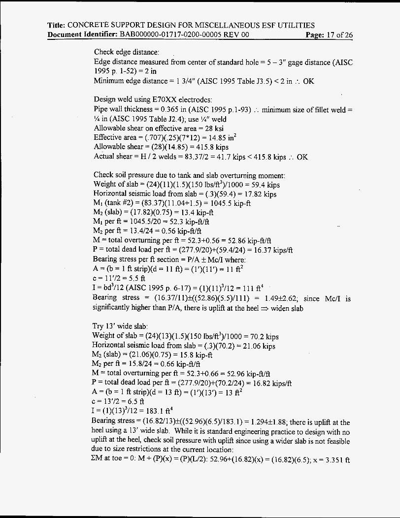
#1 Mixing #2 Storage
8’ (b x 28’ long tank (TYP) #3 Storage To Underground
EXISTING TANK LAYOUT
W6x15
10’6’’ I 10’6’’
TANK FRAME PLAN
Wheels (one side only) Center wood support on one tank only
TANK FRAME ELEVATIONS
Tank legs 6” (b pipe (TYF’)
The weight of the (3) 10,000 gallon tanks will be calculated using !A inch plate steel. Since the tanks are transportable (i.e., equipped with wheels), the tanks will be anchored to a series of pier walls in order lift the tank wheels off of the ground and provide a stable base.
Calculate tank loads: Weight of tank = [ ( X > ( S / ~ ) ~ ( ~ ) + ( X ) ( S ) ( ~ S ) ] ( % /12)(490 lbs/fi3 (AISC 1995 page 6-8))

Title: CONCRETE SUPPORT DESIGN FOR MISCELLANEOUS ESF UTILITIES Document Identifier: BAB000000-01717-0200-00005 REV 00 Page: 20 of26
I
-
44’
/
= 82 10 lbs Weight ofwater = (10000)(62.4 lbs/ft3)/(7.48 gal/ A3) = 83422 lbs Weight of frame: ClOx15.3: (2)(22)(15.3) = 673.2 lbs W6x15: (3)(8)(15) = 360 lbs 6” + pipe (18.97 lbs/A (AISC 1995 page 1-93)): [(6)(4.8)+(2)(3.1)](18.97) = 664 lbs 3” + pipe (7.58 1bdA (AISC 1995 page 1-93)):
Beams: (2)(21)(7.58) = 318.4 lbs Cross bracing (short side): (4)[(3’+4.8’)”](7.58) = 171.6 lbs Cross bracing (long side): (8)[((10.5/2)2+4.82)’](7.58) = 43 1.4 lbs Total 3” pipe weight = 318.4+171.6+431.4 = 921.4 lbs
Total fiame weight = 673.2+360+664+921.4 = 2619 lbs The weight of the wheels can be neglected since they are minor in comparison to the weights of the tank and the water. Total weight = 8210 + 83422 + 2619 = 94251 lbs, say 94500 lbs= 94.5 kips
The impact load on the pier walls from placing the tanks can be neglected since it is minor in comparison to the total dead load on the pier walls from the full tank: Impact load = 25% dead load of empty tank = (.25)(8210+2619) = 2707 lbs << 94.5 kips
7.3.2 Slab Design
Try 44’ x 36’ x 1’ slab with 12” x 18” pier walls (Note: The distances between tanks on the slab and from the edges of the slab have been determined in the field to accommodate miscellaneous equipment, hoses, etc.):
36’

Title: CONCRETE SUPPORT DESIGN FOR MISCELLANEOUS ESF UTJLITIES Document Identifier: BAB000000-0 17 17-0200-00005 REV 00 Page: 21 of 26
Check bearing pressure on soil (load is transferred at 45’ relative to thickness of slab): Bearing area on slab = AI = (1’)(44’) = 44 R2 Bearing area on soil = A2 = (1+(2)(1))*(44) = (3)(44) = 132 R2 Tank load = (3 tanks)(94.5)/(3 pier walls) = 94.5 kips Slab concrete weight = (132)(1)(150 lbs/ft3 (4.1.5))/1000 = 19.8 kips Pier wall concrete weight = (1)(18/12)(44)(15O)/lOOO = 9.9 kips D = Total dead load = 94.5+19.8+9.9 = 124.2 kips E = Seismic load (4.1.3) = (.3)(124.2) = 37.3 kips Conservatively calculate the bearing pressure on the soil using factored loads: U = Factored combination load = 0.751: 1.4D + 1.7L + 1.7( 1. lE)] (ACI 1995 Sections 9.2.2 & 9.2.3) = (.75)[(1.4)(124.2)+(1.7)(1.1)(37.3)] = 182.7 kips qs = bearing pressure = U/A2 = 182.7*1000/132 = 1384 psf < p = 5000 psf (4.1.1) :. OK
Check shear through slab: D = 94.5+9.9 = 104.4 kips (ignore the dead weight of the slab as it will be subtracted from the net pressure in the calculation of the maximum shear) E = (.3)(104.4) = 31.32 kips P, = Total factored pier load = (.75)[(1.4)(104.4)+(1.7)(1.1)(31.32)] = 154 kips Vu 5 $Vn = $(Vc+Vs) = O.S5Vc (ACI 1995 Sections 1 1.1.1 & 9.3.2.3) V, = (2)(fc’)”b,d (ACI 1995 Section 11.3.1.1) f,’ = 4000 psi (4.1.2) d = distance from compression fiber to center of rebar = 12 - 3” cover (ACI 1995 Section 7.7.1) - ’/? diameter of rebar, say % inch = 8 . 5 in b, = width shear plane = 44*(12*2) = 1056 in $Vc = (.85)(2)(4000)”(1056)(8.5)/1000 = 965 kips > P, = 154 kips :. OK
Check bearing on concrete: Max bearing < $(0.85fc’A1) (ACI 1995 Section 10.17.1) $ for bearing = 0.7 (ACI 1995 Section 9.3.2.4) Max bearing = (.7)(.85)(4)(44*12*12) = 15080 kips > P, = 154 kips :. OK
Calculate M,, (using 1’ section across slab):
\ <
\ \ 7’ 6’‘ \ \ 10’ 6”
7’ 67‘ Ili b,\\ , 10’ 6” ;’ I; 6;. + t + t t t t t t t t t t t
0
P, = 154 kips which creates a pressure (p,) on the soil = PJA2 = 15411 32 = 1.17
The dead weight of the slab can be ignored as it will be subtracted from the net kip/R2

Title: CONCRETE SUPPORT DESIGN FOR MISCELLANEOUS ESF UTILITIES Document Identifier: BAB000000-0 17 17-0200-00005 REV 00 Page: 22 of26
pressure in the calculation of the maximum moment. CM at end = 0: (0)(36)~/2 = (1.17)(3)(7.5+18+28.5) :. o = 0.293 kiplft M,, at end of slab = oL2/2 (AISC 1995 page 2-302) = (.293)(7.5-0.5)2/2 = 7.18 kip- ft (bottom reinforcement) Mmx between pier walls = oL2/8 (AISC 1995 page 2-296) = (.293)(10.5-1)2/8 = 3.31 kip-fi (top reinforcement)
.
Design reinforcement using A615 (ASTM 1996) Grade 60 rebar (4.1.6): Bottom bars: A, = Mu/@fyjd (MacGregor 1997 page 123) j z 0.925 for slabs (MacGregor 1997 page 123) @ = 0.9 (ACI 1995 Section 9.3.2.1) A, = (7.18*12)/(.9)(60)(.925)(8.5) = 0.20 in2/ft &(mi”) = 0.0018bh (ACI 1995 Section 7.12.2.1) = (.0018)(12)(12) = 0.26 in2/ft &-) (!h bottom bars & !h top bars) = .26/2 = 0.13 in2/ft < 0.20 in2/ft :. A, controls Using a spacing of 12” and #4 bars, A, = 0.20 in2/ft (ACI 1995 Appendix E) =
0.20 in2/fi :. OK Top bars: BY inspection, AS(-) = 0.13 in2/ft controls Using a spacing of 12” and #4 bars, A, = 0.20 in2/fi > 0.13 in2/ft :. OK
Design reinforcement along other direction of slab: By inspection, A,(-, = 0.26 in2/fi controls (total top and bottom) Using a spacing of 12” and #4 bars, & = (2)(.20) = 0.40 in2 > 0.26 in2 :. OK
Use a 44’ x 36’ x 1’ slab with #4 A615 (ASTM 1996) Grade 60 rebar on 12” centers each way top and bottom.
7.3.3 Pier Wall Design
Using 1’ section across slab:

I Title: CONCRETE SUPPORT DESIGN FOR MISCELLANEOUS ESF UTILITIES Document Identifier: BAl3000000-0 17 17-0200-00005 REV 00 Page: 23 of26
P, = 94.5 kips (7.3.2) unfactored = 139 kips; P, per ft = 139/44 = 3.16 kip/ft Ht = factored horizontal seismic tank load per ft (4.1.3) = (.3)(3.16) = 0.95 kip/A P, = 9.9 kips (7.3.2) unfactored 3 0.75[(1.4)(9.9)+(1.7)(1.1)(.3*9.9)] factored =
14.6 kips; P, per A = 14.6/44 = 0.33 kip/ft H, = factored horizontal seismic concrete load per ft = (.3)(.33) = 0.10 kip/A ybr tank = 812 (center oftank) + 3.1 (short leg) + (6 (W6x15) + 2.6 (ClOx15.3 flange
0.75[(1.4)(94.5)+(1.7)(1.1)(.3*94.5)] factored
(AISC 1995 p. 1-40)))/12 = 7.82 A CMA: Mu = (.95)(7.82+18/12)+(. 10)(9/12) = 8.93 kip-ft/ft
Design reinforcement using A615 (ASTM 1996) Grade 60 rebar (4.1.6): A, = M,/$fyjd (MacGregor 1997 page 123) j z 0.875 for beams (MacGregor 1997 page 123) $ = 0.7 (ACI 1995 Section 9.3.2.2) d = distance from compression fiber to center of rebar = 12 - 2” cover (ACI 1995 Section 7.7.1) - % diameter of rebar, say % inch = 9.5 in A, = (8.93*12)/(.7)(60)(.875)(9.5) = 0.31 in2/ft A,(min) = 0.0018bh (ACI 1995 Section 7.12.2.1) = (.0018)(18)(12) = 0.39 in2/ft There will be one bar per each side of pier wall 3 &(min) = .39/2 = 0.20 in2/ft <- 0.31 in2/ft :. A, controls Using a spacing of 12” and #5 dowels both faces, A, = 0.3 1 in2/ft (ACI 1995 Appendix E) = 0.3 1 in2/ft :. OK
Calculate development length:
db = diameter bar = 0.625 in (ACI 1995 Appendix E) a = reinforcement location factor = 1.0 (ACI 1995 Section 12.2.4) p = coating factor = 1.0 (ACI 1995 Section 12.2.4) h = lightweight aggregate concrete factor = 1.0 (ACI 1995 Section 12.2.4) f,’ = 4000 psi (4.1.2) ld = (.625)(60000)(1)(1)(1)/(25)(4000)” = 24 in > Id(&) = 12 in (ACI 1995 Section 12.2.1) :. ld controls Since Id exceeds both the height of the pier wall and the thickness of the slab, design hooked reinforcement: lhb = 1200dd(f,‘)” (ACI 1995 Section 12.5.2) = (1200)(.625)/(4000)” = 12 in ldh = lhb * factors listed in ACI 1995 Section 12.5.3 which are all not applicable :. 1dh
= 12 in ldh OK into pier; use 90” hook into pier wall and 90” hook into slab
Design horizontal reinforcement using A6 15 (ASTM 1996) Grade 60 rebar: The horizontal reinforcement will be controlled by A,(min).
ld = dbfflph/25(fc‘)” (ACI 1995 Section 12.2.2)
A,(jnin) = (.0018)(18)(12) = 0.39 in2/ft There will be two bars per each side of the pier wall minimum in2/ft
A$fii,) = .39/4 = 0.10
Title: CONCRETE SUPPORT DESIGN FOR MISCELLANEOUS ESF UTILITIES Document Identifier: BAT3000000-0 17 17-0200-00005 REV 00 Page: 24 of 26
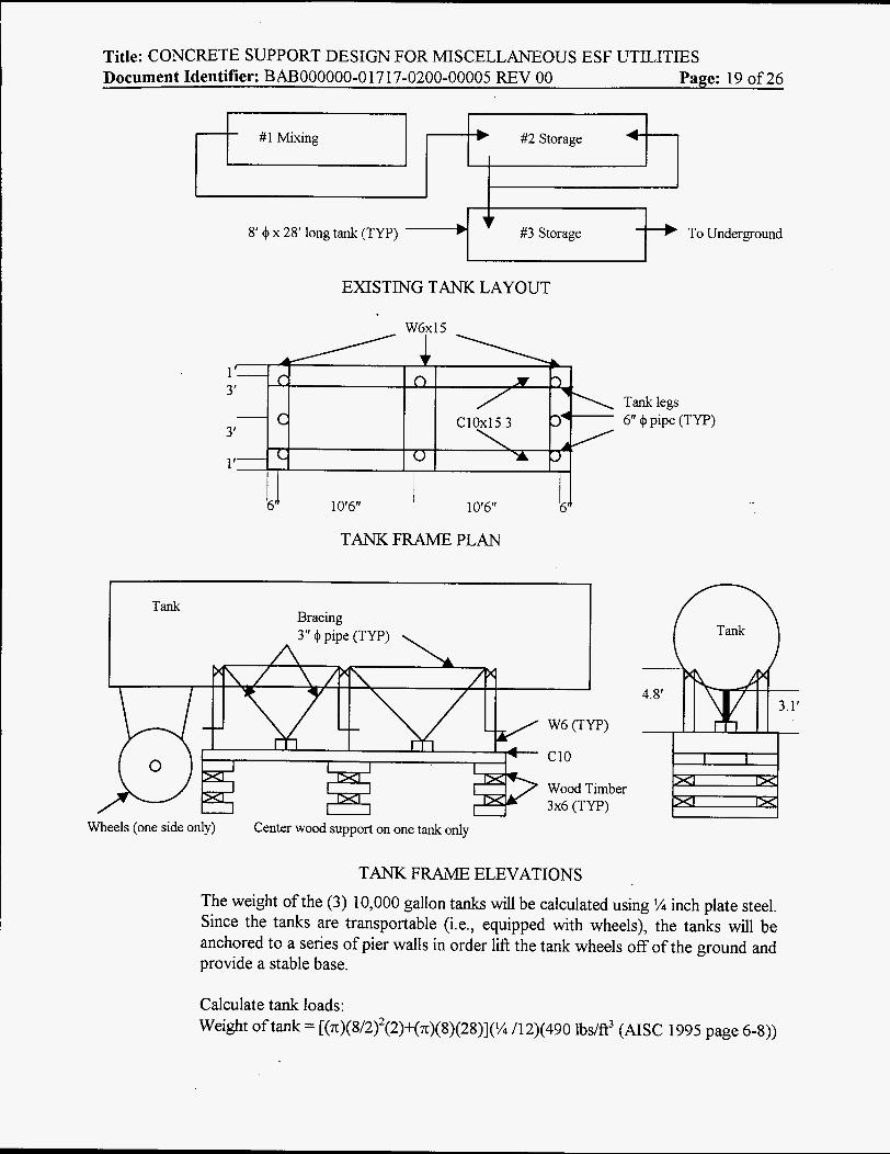
Using a spacing of 12” and #4 bars to ensure load transfer between supports, 4, =
0.20 in2/R (ACI 1995 Appendix E) > 0.10 in2/R :. OK
Check buckling of pier wall:
4Pnw = design axial load strength = 0.55$fc‘AJ 1-(klJ32h)2] where 4 = 0.70 and k = 0.8 (ACI 1995 Section 14.5.2) In order to use this empirical formula, the following conditions must be met: e
e
e
e
-
pvmh = ratio of vertical reinforcement area to gross concrete area = 0.0012 (ACI 1995 Sections 14.3.2); 4, = (2)(.31) = 0.62 in2& 4 = (12)(12) = 144 in2& p = (.62)/(144) = 0.0043 > 0.0012 :. OK p b = ratio of horizontal reinforcement area to gross concrete area = 0.0020 (ACI 1995 Sections 14.3.3); 4 , h = (4)(.20) = 0.80 in2& & = (12)(12) = 144 in2& p = (.80)/(144) = 0.0056 > 0.0020 :. OK 4, = area vertical reinforcement < 0.01 Ag (ACI 1995 Section 14.3.6) = (.01)(144) = 1.44 in2/R > 0.62 in2/R :. OK Resultant of all factored loads is located in middle third of wall (ACI 1995 Section 14.5.1): tank base plates will be centered on pier walls :. OK
$Pnw = (.55)(.7)(4)(144)[1-((.8)(18)/(32)(12))2] = 221.4 kip/& > Pt = 3.16 kip/R :. OK
Design base plate / anchor bolts: To transfer the loads from the tank frame bottom members (ClOx15.3) to the concrete pier wall, base plates will be welded to the C10 and anchored to the pier wall. (6) base plates and anchor bolts will be used per tank frame, or ( 3 ) per C10. NOTE: The structural integrity of the existing tank frame has not been evaluated.
H = (.3)(94.5) = 28.4 kips = 28.4/6 = 4.73 kipsholt Using 7/8” 4 A307 (ASTM 1997a) anchor bolts (4.1.7), bolt = ( ~ ) ( 7 / 1 6 ) ~ = 0.60 in2 F, = allowable shear stress = 10 ksi (AISC 1995 p. 4-5) f, = actual shear stress = H/&,lt = (4.73)/(.6) = 7.9 ksi < 10 ksi :. OK H acts through the center of mass (yba) which produces an overturning moment (m). If M, > resisting moment (MJ from P, check tensile force (T) on the anchor bolts:
P = 94.5 kips
ybar = 7.82 R M, = H * Ybar = (28.4)(7.82) = 222.1 kip-ft M, = P * Tank width/2 = (94.5)(8/2) = 378 kip-R > 222.1 kip-R 3 no tension on

Title: CONCRETE SUPPORT DESIGN FOR MISCELLANEOUS ESF UTILITIES Document Identifier: BAB000000-017 17-0200-00005 REV 00 Page: 25 of 26
anchor bolts :. OK Factor of safety (FS) for overturning = 37U222.1 = 1.7 :. OK Try 14" x 6" x 5/8" A36 (ASTM 1997b) plate (4.1.8):
Check edge distance: Centering bolt hole, edge distance measured fiom center of standard hole = (14-1 1)/2 =l%iIf Minimum edge distance = 1%" (AISC 1995 Table J3.5) = 1 % in :. OK
Check allowable service load on embedded bolts: For 718" bolts with a minimum embedment = 6", an edge distance = 5%" (measured fiom the anchor axis to the fiee edge), and a spacing = lo%", allowable shear load = 4050 lbs (ICBO 1997 Table 19-D). Per footnote 3 in Table 19-D, a 1/3 increase is allowed with seismic forces = allowable shear load = (1.333)(4050) = 5399 lbs. Actual edge distance = 12"/2 = 6" :. OK Actual spacing is adequate by inspection. Actual m o l t = 4.73 kips/bolt < 5.399 kips/bolt :. OK
Design weld using E70XX electrodes (4.1.9): Base plate thickness = 5/8 in; ClOx15.3 flange thickness = 0.436 in (AISC 1995 page 1-40) :. minimum size of fillet weld = % in (AISC 1995 Table J2.4); use '/4 in weld Allowable shear on effective area = 0.30 x nominal tensile strength of weld metal (AISC 1995 Table J2.5) = (.3)(70) = 21 ksi * 1.333 allowable seismic increase (AISC 1995 Section A5.2) = 28 ksi Effective area = (0.707)(weld thickness)(weld length) (AISC 1995 Section J2.a) = (.707)(.25)(2*6 (welded full length on both sides of C10)) = 2.121 in2 Allowable shear = (28)(2.12 1) = 59.4 kips Actual shear = H / 2 welds = 4.73/2 = 2.4 kips < 59.4 kips :. OK
Check soil pressure due to tank and slab overturning moment: By inspection, soil pressure is OK.
Check bearing on pier wall: Max bearing < +(0.85f,'Al) (ACI 1995 Section 10.17.1) + for bearing = 0.7 (ACI 1995 Section 9.3.2.4) A = area of plate = (6)(14) = 84 in2 Max bearing = (.7)(.85)(4)(84) = 200 kips > Pt (factored)/plate = 139.1/6 = 23.2 kips
Title: CONCRETE SUPPORT DESIGN FOR MISCELLANEOUS ESF UTILITIES Document Identifier: BAB000000-01717-0200-00005 REV 00 Page: 26 of26
(approximately); the actual bearing pressure is not uniformly distributed since the C10 is not centered on the base plate. However, computed ratio is so large that bearing is OK by inspection.
The wind pressure generated from a design wind speed of 75 mph (4.1.4) on the tanks is minor in comparison to the horizontal seismic load (see 7.2.4) :. anchors are adequate.
Use 12” x 18” pier walls with #4 A615 (ASTM 1996) Grade 60 horizontal rebar on 12” centers and anchored to the slab with #5 A615 (ASTM 1996) Grade 60 vertical rebar on 12“ centers hooked 90” into both the slab and the pier wall. Use (6) 14“ x 6” x 518” base plates welded to the existing tank fiame. Use (6) 7/8” 4 A307 (ASTM 1997a) bolts embedded a minimum of 6“ to anchor each base plate to the pier wall.
8. CONCLUSIONS
8.1 A 44’ x 12’ x 1’ concrete slab with #4 A615 (ASTM 1996) Grade 60 rebar on 12” centers each way top and bottom is adequate to support Waste Water Tanks #1 & #3. A 24’ x 13’ x 1’6” slab with #4 A61 5 (ASTM 1996) Grade 60 rebar on 12“ centers long way bottom, #5 A615 (ASTM 1996) Grade 60 rebar on 12” centers short way bottom, #9 A615 (ASTM 1996) Grade 60 rebar on 12” centers long way top, and #4 A615 (ASTM 1996) Grade 60 rebar on 12“ centers short way top is adequate to support Waste Water Tank #2. Use (8) 3/4“ 4 A307 (ASTM 1997a) anchor bolts embedded a minimum of 5” to anchor Tank #1 to the new slab. Use (12) 1” 4 A307 (ASTM 1997a) anchor bolts embedded a minimum of 7” to anchor Tank #2 to the new slab; weld (2) L 5” x 5“ x 5/8” A36 (ASTM 1997b) minimum angles down the length of the existing outer 10” 4 pipes using E70XX electrodes and % inch welds. Use (4) 314’’ 4 A307 (ASTM 1997a) anchor bolts embedded a minimum of 5” to anchor Tank #3 to the new slab; weld (4) 3“ x 3” x 5/8” A36 (ASTM 199%) minimum plates to the existing tank using E70XX electrodes and % inch welds.
8.2 A 44’ x 36’ x 1‘ concrete slab with #4 A615 (ASTM 1996) Grade 60 rebar on 12” centers each way top and bottom is adequate to support the Non-Potable Water System chemical mixing and storage tanks. The tanks will bear on (3) 12“ x 18” concrete pier walls with #4 A615 (ASTM 1996) Grade 60 horizontal rebar on 12” centers and anchored to the slab with #5 A615 (ASTM 1996) Grade 60 vertical dowels on 12” centers hooked 90” into both the slab and the pier wall. For each tank, weld (6) 14” x 6“ x 98” A36 (ASTM 199%) minimum base plates full length on both sides of the existing C 10 tank frame using E7OXX electrodes and ‘/4 inch welds. Use (6) 718’’ 4 A307 (ASTM 1997a) minimum bolts embedded a minimum of 6” to anchor base plates to the pier wall (one bolt per base plate).
9. ATTACHMENTS Not Used


![とっとりの教育 - Tottori Prefecture...^êVJXÊ QjöXÊaÊ QQÊ{ f7R l^ QnÊq {{olJ Qm Q Qa QxÏQ z jò ] QRþ QQ R ^ QWêlR QgâqKjÖ Qa k zz QQ WÎWê _ Q QÊ{ nÊq QR ^²](https://static.fdocuments.us/doc/165x107/610f67215182b50e54404123/e-tottori-prefecture-vjx-qjxa-qq-f7r-l.jpg)