Non-Linear Static Analysis of RC Framed Buildings with ... · 7) Elastic (Linear) Behavior: Refers...
10
IJSRD - International Journal for Scientific Research & Development| Vol. 3, Issue 09, 2015 | ISSN (online): 2321-0613 All rights reserved by www.ijsrd.com 264 Non-Linear Static Analysis of RC Framed Buildings with Plan Irregularity Mohammed Irfan 1 Sheik Abdulla 2 1 M.Tech Student (Structural Engineering) 2 Professor 1,2 Department of Civil Engineering 1,2 Khaja Banda Nawaz College of Engineering, Gulbarga - 585104 Abstract— Herein present study 3 new R.C structures of unsymmetrical in plan (irregular) (designed as per IS 456:2000) is taken for analysis: 4, 8 & 20 storey cover the large variety of low rise building, medium rise building & high rise building constructions. For different modeling were included through three models for every buildings were bare frame with no infill wall, with infill wall as membrane, replacing infill wall as equivalent diagonal strut in earlier model. The equivalent strut method is convenient for modeling the walls in a large buildings. The pushover analysis carried out by using ETABS 9.5. Buildings situated in Zone-IV have analyzed for comparative studies prepared for above membranes. The analysis results are measures in terms of Story Displacement, Drift ratio and Forced Responses such as Base Tensional Moment & Base Shear. Structures were designed to obtain the performance level, allow immediate tenancy, is defined as performance based design. CSM (capacity spectrum method) is used for seismic performance of RC Structures. Key words: R.C structures, CSM I. INTRODUCTION A. General An earthquake is the sudden movement or tremors causing the greatest damages as it originate naturally below the earth surface. Earthquake forces are sudden in the nature & unexpected. Since it exclude shock waves due to manmade explosions and nuclear tests etc. The whole earth is made up of plates. The intersection among these plates is called faults. In Indian context fault is the main boundary extending through the terrain province all the way from Himachal Pradesh, Uttarakhand Assam, and Bihar to Burma. Plates are comes down along Andaman Nicobar & Bay of Bengal & into Indonesia. As the plate place of or move the rocks are subject to stress, unexpectedly facture develops & this is called as an earthquake. The designing system should be enhancing for breaking down the structures under demonstration of these powers. Seismic tremor does not murder the people but rather structures do. It's most imperative obligation of an auxiliary planner to take out parameter from prior encounters and take into all potential hazard that the structure can be subjected to be in future utilized with the end goal of protected and secure outline of the structure. Execution based configuration is increasing new angle in the seismic outline theory in which the close field ground movement (quickening) is to be measured. Heaps of Earthquake are chosen painstakingly displayed in order to assess the real execution of structure with an unmistakable seeing in order to harm is evaluated. Pushover analysis is a procedure where structural loading is gradually applied . by the result of which weak links as well as the failure patterns of the structure are easily distinguished. B. Performance Based Seismic Design Necessity Since the impacts of real quakes (as mid 1980s) it is chosen that the seismic dangers into the urban territories are expanding and are far from socio-monetarily attractive levels. There is an imperative need to topple this circumstance and it is comprehended that a standout amongst the most proficient methods for doing this from: 1) The advancement of extra predictable seismic standard and code necessities than those at present realistic and 2) Their brutal execution for the complete designing of new building conveniences. An execution based configuration (PBSE) is expected at computing the basic harm base on precise assessment of suitable reaction element. This is normal that if more exact examinations are completed, tallying all conceivable critical elements worried in the basic conduct. C. Objectives the Present Study 1) Objectives Making building models for flexible and inelastic system of assesses. Calculating horizontal forces of buildings by using nonlinear pushover analysis method to evaluate the results. To study the effect of plan irregularity on the fundamental natural period of the building and its effect on performance of the structure during earthquake for different building models selected. Finding out the storey displacements and storey drifts at each storey by using nonlinear pushover method. To study the load carrying capability of different frames using masonry wall as infill and equivalent diagonal strut in terms of Base Shear at performance point. Discovering the execution level of the building utilizing nonlinear weakling investigation. II. METHODOLOGY A. General Terms 1) Capacity: The normal extreme quality (in flexure, shear, or hub stacking) of a basic segment barring the lessening (considers regularly utilized configuration of solid individuals. The limit more often than not alludes to the quality at the yield purpose of the component or structure's ability bend. For misshapening controlled segments, limit past as far as possible for the most part incorporates the impacts of strain solidifying.
Transcript of Non-Linear Static Analysis of RC Framed Buildings with ... · 7) Elastic (Linear) Behavior: Refers...

IJSRD - International Journal for Scientific Research & Development| Vol. 3, Issue 09, 2015 | ISSN (online): 2321-0613
All rights reserved by www.ijsrd.com 264
Non-Linear Static Analysis of RC Framed Buildings with Plan
Irregularity Mohammed Irfan
1 Sheik Abdulla
2
1M.Tech Student (Structural Engineering)
2Professor
1,2Department of Civil Engineering
1,2Khaja Banda Nawaz College of Engineering, Gulbarga - 585104
Abstract— Herein present study 3 new R.C structures of
unsymmetrical in plan (irregular) (designed as per IS
456:2000) is taken for analysis: 4, 8 & 20 storey cover the
large variety of low rise building, medium rise building &
high rise building constructions. For different modeling
were included through three models for every buildings
were bare frame with no infill wall, with infill wall as
membrane, replacing infill wall as equivalent diagonal strut
in earlier model. The equivalent strut method is convenient
for modeling the walls in a large buildings. The pushover
analysis carried out by using ETABS 9.5. Buildings situated
in Zone-IV have analyzed for comparative studies prepared
for above membranes. The analysis results are measures in
terms of Story Displacement, Drift ratio and Forced
Responses such as Base Tensional Moment & Base Shear.
Structures were designed to obtain the performance level,
allow immediate tenancy, is defined as performance based
design. CSM (capacity spectrum method) is used for seismic
performance of RC Structures.
Key words: R.C structures, CSM
I. INTRODUCTION
A. General
An earthquake is the sudden movement or tremors causing
the greatest damages as it originate naturally below the earth
surface. Earthquake forces are sudden in the nature &
unexpected. Since it exclude shock waves due to manmade
explosions and nuclear tests etc. The whole earth is made up
of plates. The intersection among these plates is called
faults. In Indian context fault is the main boundary
extending through the terrain province all the way from
Himachal Pradesh, Uttarakhand Assam, and Bihar to
Burma. Plates are comes down along Andaman Nicobar &
Bay of Bengal & into Indonesia. As the plate place of or
move the rocks are subject to stress, unexpectedly facture
develops & this is called as an earthquake.
The designing system should be enhancing for
breaking down the structures under demonstration of these
powers. Seismic tremor does not murder the people but
rather structures do. It's most imperative obligation of an
auxiliary planner to take out parameter from prior
encounters and take into all potential hazard that the
structure can be subjected to be in future utilized with the
end goal of protected and secure outline of the structure.
Execution based configuration is increasing new angle in the
seismic outline theory in which the close field ground
movement (quickening) is to be measured. Heaps of
Earthquake are chosen painstakingly displayed in order to
assess the real execution of structure with an unmistakable
seeing in order to harm is evaluated.
Pushover analysis is a procedure where structural
loading is gradually applied . by the result of which weak
links as well as the failure patterns of the structure are
easily distinguished.
B. Performance Based Seismic Design Necessity
Since the impacts of real quakes (as mid 1980s) it is chosen
that the seismic dangers into the urban territories are
expanding and are far from socio-monetarily attractive
levels. There is an imperative need to topple this
circumstance and it is comprehended that a standout
amongst the most proficient methods for doing this from:
1) The advancement of extra predictable seismic standard
and code necessities than those at present realistic and
2) Their brutal execution for the complete designing of
new building conveniences.
An execution based configuration (PBSE) is
expected at computing the basic harm base on precise
assessment of suitable reaction element. This is normal that
if more exact examinations are completed, tallying all
conceivable critical elements worried in the basic conduct.
C. Objectives the Present Study
1) Objectives
Making building models for flexible and inelastic
system of assesses.
Calculating horizontal forces of buildings by using
nonlinear pushover analysis method to evaluate the
results.
To study the effect of plan irregularity on the
fundamental natural period of the building and its effect
on performance of the structure during earthquake for
different building models selected.
Finding out the storey displacements and storey drifts at
each storey by using nonlinear pushover method.
To study the load carrying capability of different frames
using masonry wall as infill and equivalent diagonal
strut in terms of Base Shear at performance point.
Discovering the execution level of the building utilizing
nonlinear weakling investigation.
II. METHODOLOGY
A. General Terms
1) Capacity:
The normal extreme quality (in flexure, shear, or hub
stacking) of a basic segment barring the lessening (considers
regularly utilized configuration of solid individuals. The
limit more often than not alludes to the quality at the yield
purpose of the component or structure's ability bend. For
misshapening controlled segments, limit past as far as
possible for the most part incorporates the impacts of strain
solidifying.

Non-Linear Static Analysis of RC Framed Buildings with Plan Irregularity
(IJSRD/Vol. 3/Issue 09/2015/065)
All rights reserved by www.ijsrd.com 265
2) Limit Curve:
it is the bend of aggregate parallel power, V, following up
on a structure versus horizontal redirection, d of the
structure which is known as the "mark" bend.
3) Limit Range Method:
A nonlinear static analysis procedure that provides a
graphical representation of the expected seismic
performance of the existing or retrofitted structure by the
intersection of the structure's capacity spectrum with a
response spectrum (demand spectrum) representation of the
earthquake's displacement demand on the structure. The
intersection is the performance point, and the displacement
coordinate, dp, of the performance point is the estimated
displacement demand on the structure for the specified level
of seismic hazard.
4) Components or Members:
The local concrete members that comprise the major
structural elements of the building such as columns, beams,
slabs, wall panels, boundary members, joints, etc. Concrete
frame building: A building with a monolithically cast
concrete structural framing system composed of horizontal
and vertical elements which support all vertical gravity
loads and also provide resistance to all lateral loads through
bending of the framing elements.
5) Ultimatum:
It is spoken to by an estimation of the-removals or
disfigurements that the structure is relied upon to
experience.
6) Ultimatum Range:
The reduced response spectrum used to represent the
earthquake ground motion in the capacity spectrum method
7) Elastic (Linear) Behavior:
Refers to the first segment of the bi-linear load-deformation
relationship plot of a component, element, or structure,
between the unloaded condition and the elastic limit or yield
point.
8) Performance Objective:
A desired level of seismic performance of the building
(performance level), generally described by specifying the
maximum allowable (or acceptable) structural and
nonstructural damage, for a specified level of seismic
hazard.
B. Pushover Analysis
In Target examination, a static level power profile, normally
corresponding to the outline power profiles indicated in the
codes, is connected to the structure. The power profile is
then increased in little steps and the structure is investigated
at every stride. As the heaps are expanded, the building
experiences yielding at a couple of areas. Each time such
yielding happens, the basic properties are changed roughly
to mirror the yielding. The investigation is proceeded till the
structure breakdown, or the building achieves certain level
of sidelong dislodging.
Fig. 3.1: Inverted Triangular Loading for Pushover Analysis
1) Need for Pushover Analysis
The models utilized as a part of this examination which is
subjected to seismic strengths acquired from configuration
spectra and decreased by power lessening elements.
Force reduction factors recommended in codes of
practice are approximate and do not necessarily represent
the specific structure under consideration.
When critical zones of a structure enter into the
inelastic range, the force and deformation distribution
change significantly. This change is not represented by a
global reduction of forces
The mechanism that will most likely perpetuate
collapse is unlikely to be that represented by the elastic
action and deformation distribution.
The global and particularly the local distribution of
deformations in the inelastic range may bear no resemblance
to those in the elastic range. The same applies to the values
of deformations, not just the distribution
C. Equivalent Diagonal Strut Method
Diagonal strut modeling is most popular. Specialists have
attempted to demonstrate the block stone work in numerous
corner to corner struts, i.e. single strut, two inclining struts,
and three askew struts. Perceiving results on this trial they
conclude that the single diagonal strut is the most effective
method of modeling for the masonry infill panel that work
best. Infill walls is modeled using diagonal strut method.
The infill walls assumed as diagonal strut and modeling of
frame is done as per beam element. Frame analysis
techniques are used for the elastic analysis. The idealization
is based on the assumption that there is a no bond between
frame and infill. Although there are various guess about the
width of diagonal strut which depends on length of contact
between the wall & the columns (αh) and between wall &
beams (αL).
1) Determination of Equivalent Strut Width
Fig. 3.7: Equivalent diagonal strut
The following are the formulae to calculate the width and
length of strut given Stafford Smith (1966) based on the
assumption that beams are on elastic foundation. Developed
the formulations for αh and αL on the basis of beam on an
elastic foundation.
4
2sin
4
2
tE
hIE
m
cf
h
4
2sin
4
tE
LIE
m
bf
L
where, Em = Elastic modulus of masonry wall
Non-Linear Static Analysis of RC Framed Buildings with Plan Irregularity
(IJSRD/Vol. 3/Issue 09/2015/065)
All rights reserved by www.ijsrd.com 266
Ef = Elastic modulus of frame material
t,h,L = Thickness, height and length of the infill wall
Ic = Moment of inertia of the column
Ib = Moment of inertia of the beam
θ = tan-1
(h/L)
Hendry (1998) proposed the following equation to
determine the equivalent or effective strut width w, where
the strut is assumed to be subjected to uniform compressive
stress
22
2
1Lhw
2) Irregular Structure Effects
Impacts like backstay impacts can happen anyplace in a
building where there is a critical change in horizontal quality
or solidness in one story in respect to nearby stories. In tall
structures, this can happen at Asymmetric, which are areas
where the seismic power opposing framework altogether
changes in measurement over the base, Because of distortion
similarity and relative solidness impacts, the shorter
component in such an arrangement will draw in bigger
seismic strengths through the floor stomachs and gatherers
at the top.
Lopsided can likewise make a quality brokenness
that can bring about moved nonlinear conduct in the
framework at the area of the Asymmetric. On account of
solid dividers, the most alluring nonlinear conduct is a
flexural plastic pivot system at the base of the divider. A
configuration objective in such structures would be to
minimize torsional erraticism’s at the base of the structure
III. ANALYTICAL MODELLING
A. General
The main aim of doing a pushover analysis is to prevent a
building from damages and to prevent the damages on
structural components in oreder to estimate the performance
limit of the building .
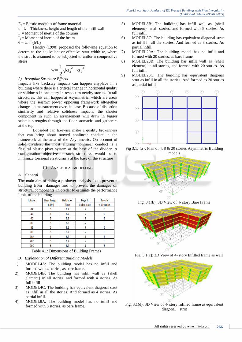
Table 4.1: Dimensions of Building Frames
B. Explanation of Different Building Models
1) MODEL4A: The building model has no infill and
formed with 4 stories, as bare frame.
2) MODEL4B: The building has infill wall as {shell
element} in all stories, and formed with 4 stories. As
full infill
3) MODEL4C: The building has equivalent diagonal strut
as infill in all the stories. And formed as 4 stories. As
partial infill.
4) MODEL8A: The building model has no infill and
formed with 8 stories, as bare frame.
5) MODEL8B: The building has infill wall as {shell
element} in all stories, and formed with 8 stories. As
full infill
6) MODEL8C: The building has equivalent diagonal strut
as infill in all the stories. And formed as 8 stories. As
partial infill
7) MODEL20A: The building model has no infill and
formed with 20 stories, as bare frame.
8) MODEL20B: The building has infill wall as {shell
element} in all stories, and formed with 20 stories. As
full infill
9) MODEL20C: The building has equivalent diagonal
strut as infill in all the stories. And formed as 20 stories
as partial infill
Fig 3.1: {a}: Plan of 4, 8 & 20 stories Asymmetric Building
models
Fig. 3.1(b): 3D View of 4- story Bare Frame
Fig. 3.1(c): 3D View of 4- story Infilled frame as wall
Fig. 3.1(d): 3D View of 4- story Infilled frame as equivalent
diagonal strut
Non-Linear Static Analysis of RC Framed Buildings with Plan Irregularity
(IJSRD/Vol. 3/Issue 09/2015/065)
All rights reserved by www.ijsrd.com 267
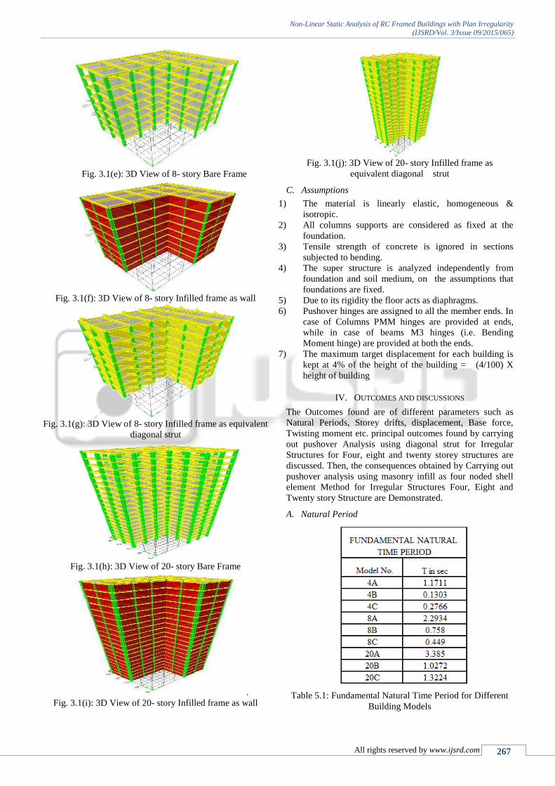
Fig. 3.1(e): 3D View of 8- story Bare Frame
Fig. 3.1(f): 3D View of 8- story Infilled frame as wall
Fig. 3.1(g): 3D View of 8- story Infilled frame as equivalent
diagonal strut
Fig. 3.1(h): 3D View of 20- story Bare Frame
.
Fig. 3.1(i): 3D View of 20- story Infilled frame as wall
Fig. 3.1(j): 3D View of 20- story Infilled frame as
equivalent diagonal strut
C. Assumptions
1) The material is linearly elastic, homogeneous &
isotropic.
2) All columns supports are considered as fixed at the
foundation.
3) Tensile strength of concrete is ignored in sections
subjected to bending.
4) The super structure is analyzed independently from
foundation and soil medium, on the assumptions that
foundations are fixed.
5) Due to its rigidity the floor acts as diaphragms.
6) Pushover hinges are assigned to all the member ends. In
case of Columns PMM hinges are provided at ends,
while in case of beams M3 hinges (i.e. Bending
Moment hinge) are provided at both the ends.
7) The maximum target displacement for each building is
kept at 4% of the height of the building = (4/100) X
height of building
IV. OUTCOMES AND DISCUSSIONS
The Outcomes found are of different parameters such as
Natural Periods, Storey drifts, displacement, Base force,
Twisting moment etc. principal outcomes found by carrying
out pushover Analysis using diagonal strut for Irregular
Structures for Four, eight and twenty storey structures are
discussed. Then, the consequences obtained by Carrying out
pushover analysis using masonry infill as four noded shell
element Method for Irregular Structures Four, Eight and
Twenty story Structure are Demonstrated.
A. Natural Period
Table 5.1: Fundamental Natural Time Period for Different
Building Models

Non-Linear Static Analysis of RC Framed Buildings with Plan Irregularity
(IJSRD/Vol. 3/Issue 09/2015/065)
All rights reserved by www.ijsrd.com 268
Fig. 5.1: Fundamental Natural Time Period for Different
Building Models
From above, the percentage decrease of natural
period of model 4B is 88.87% related to as model 4A, and
model 4C is 76.88% as associated to model 4A.and model
8B is 66.94% associated to as model 8A, and model 8C is
80.42% as related to model 8A.and model 20B is 69.65%
associated to as model 20A, and model 20C is 60.93% as
likened to model 20A.
B. Base Force
Table 5.2: Base Shear for Different Models
Fig. 5.2: Base Shear of all Building Models in Y Direction
Fig. 5.3: Base Shear of all Building Models in X Direction
From above, it is seen that percentage increase of
base shear are 99.85%, 98.28% and 97.24% for model 4B,
8B and 20B compared to model 4A, 8A and 20A. The
percentage increase of base shear are 98.99%, 97.51% and
89.49% for model 4C, 8C and 20C compared to model 4A,
8A and 20A.
From fig 5.3: it is seen that percentage increase of
base shear are 98.71%, 97.10% and 98.58% for model 4B,
8B and 20B related to model 4A, 8A and 20A. percentage
increase of base shear are 97.05%, 96.86% and 93.72% for
model 4C, 8C and 20C associated to model 4A, 8A and
20A.
Table 5.4: Displacement and base Force along Y Dir. For all
Building Models
Table 5.5: Displacement and base Force along X Dir. For all
Building Models

Non-Linear Static Analysis of RC Framed Buildings with Plan Irregularity
(IJSRD/Vol. 3/Issue 09/2015/065)
All rights reserved by www.ijsrd.com 269
C. Story Drifts
Table 5.6: Story Drifts for 4 Story Building Models
Fig. 5.6: Comparison of Story Drifts for 4 Story Building
Models in Y- Direction
Fig. 5.7: Comparison of Story Drifts for 4 Story Building
Models in X- Direction
The extreme percentage decreases of Storey drifts
are 26.01% and 68.15 in Y Dir. And in X Dir. 60.07% and
68.15% for model 4B and 4C as related to model 4A.
Table 5.7: Story Drifts for 8 Story Building Models
Fig. 5.8: Comparison of Story Drifts for 8 Story Building
Models in Y- Direction
Fig. 5.9: Comparison of Story Drifts for 4 Story Building
Models in X- Direction
The extreme percentage reductions of Storey drifts
are 15.87% and 64.28% in Y Dir. And in X Dir. 34.28% and
56.87% for model 8B and 8C associate to model 8A.
Table 5.8: Story Drifts for 20 Story Building Models
Non-Linear Static Analysis of RC Framed Buildings with Plan Irregularity
(IJSRD/Vol. 3/Issue 09/2015/065)
All rights reserved by www.ijsrd.com 270
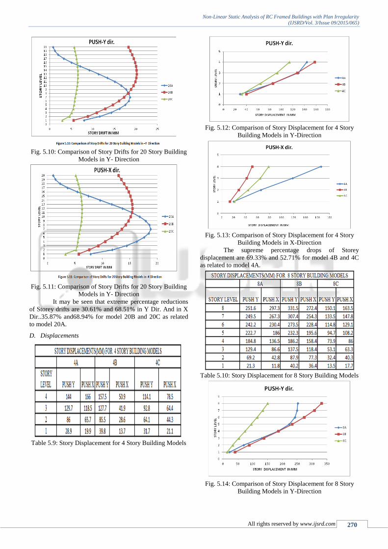
Fig. 5.10: Comparison of Story Drifts for 20 Story Building
Models in Y- Direction
Fig. 5.11: Comparison of Story Drifts for 20 Story Building
Models in Y- Direction
It may be seen that extreme percentage reductions
of Storey drifts are 30.61% and 68.51% in Y Dir. And in X
Dir..35.87% and68.94% for model 20B and 20C as related
to model 20A.
D. Displacements
Table 5.9: Story Displacement for 4 Story Building Models
Fig. 5.12: Comparison of Story Displacement for 4 Story
Building Models in Y-Direction
Fig. 5.13: Comparison of Story Displacement for 4 Story
Building Models in X-Direction
The supreme percentage drops of Storey
displacement are 69.33% and 52.71% for model 4B and 4C
as related to model 4A.
Table 5.10: Story Displacement for 8 Story Building Models
Fig. 5.14: Comparison of Story Displacement for 8 Story
Building Models in Y-Direction

Non-Linear Static Analysis of RC Framed Buildings with Plan Irregularity
(IJSRD/Vol. 3/Issue 09/2015/065)
All rights reserved by www.ijsrd.com 271
Fig. 5.15: Comparison of Story Displacement for 8 Story
Building Models in X-Direction
The concentrated percentage drop of Storey displacement
are 8.35% and 45% for model 8B and 8C as compared to
model 8A.
Table 5.11: Story Displacement for 20 Story Building
Models
Fig. 5.16: Comparison of Story Displacement for 20 Story
Building Models in Y-Direction
Fig. 5.17: Comparison of Story Displacement for 20 Story
Building Models in X-Direction
The extreme percentage reductions of Storey
displacement are 46.06% and 67.88% for model 20B and
20C as compared to model 20A.
E. Ductility Ratio () and Response Reduction Factor (R)
Table 5.12: Ductility Ratio and Response Reduction Factor
along Y Direction
Fig. 5.18: Ductility Ratio along Y direction

Non-Linear Static Analysis of RC Framed Buildings with Plan Irregularity
(IJSRD/Vol. 3/Issue 09/2015/065)
All rights reserved by www.ijsrd.com 272
Fig. 5.19: Response Reduction Factor along Y Direction
Table 5.12: Ductility Ratio and Response Reduction Factor
along X Direction
Fig. 5.20: Ductility Ratio along X direction
Fig. 5.21: Response Reduction Factor along X Direction
The ductility ratio for model 20C is larger than the
model 20A but less than 20B.
The retort reduction influence for model 20C is
superior than the model 20A but less than 20B.
V. CONCLUSIONS
1) Fundamental natural time period decreases in both use
of masonry full infill wall and equivalent diagonal
strut.
2) Storey drifts found inside the boundary as per codal
provision
3) At first hinge Base shear and displacement is more for
buildings 4C, 8C (strut) and vice versa for full infill
buildings 4B, 8B and 20B.base shear is more and
displacement is less in model 20C.(I,e.diagonal strut
model) .
4) Due to presence of the infill as equivalent strut,
displacement at top storey decreases for four, eight,
twenty stores (respectively) with respect to bare frame.
5) In fill walls should be considered for seismic analysis
of RC frames. Equivalent diagonal strut method are
effectively used for modeling the infill wall.
6) The seismic analysis of Bare frame (RC frame)
structure direct to under evaluation of Base shear.
Hence further response quantities for example storey
drift not considerable. Understatement of base force
may direct to fail of building during tremor pulsating.
So infill walls are very important to consider for
seismic analysis of structure.
7) Models 4C, 8C and 20C shows an extreme reduction
in terms of twisting moment as associate to full infill
buildings.
8) Equivalent diagonal strut building models displays
good effects in terms of hinge position. i.e; safety level
rises in diagonal strut simulations hinge status remains
in A-B.
9) For general behavior of infilled frames single diagonal
strut model is better to be used in analysis and it can be
usually correct due to its simplicity.
A. Scope for Future Work
As the performance based pushover analysis is very useful
method to design the structure at required performance
level, it can be applied in different structures
In the current concentrate full infill is taken in the
casings, halfway infill or 40% in fill can be taken in this
way, as to consider the opening in the casing incase of
(entryway and windows)
Single diagonal strut is considered in place of masonry
wall, double diagonal strut can be used.
In this current study, only irregular in plan is taken, so
additional study can be carried out for upright
indiscretions.
Maximum considered earthquake (MCE) level can be
taken for life safety performance level.
REFERENCES
[1] Kappos, A. J., Stylianidis, K. C. and Michailidis, C. N.,
(1998), “Analytical models for brick masonry infilled
R/C frames under lateral loading”, Journal of
Earthquake Engineering, Vol. 2, No.1, 59-87

Non-Linear Static Analysis of RC Framed Buildings with Plan Irregularity
(IJSRD/Vol. 3/Issue 09/2015/065)
All rights reserved by www.ijsrd.com 273
[2] Fajfar P. 1999. Capacity spectrum method based on
inelastic demand spectra. Earthquake Engineering and
Structural Dynamics; pages 979–993
[3] Priestley MJN & Kowalsky MJ. 2000 Direct
displacement-based seismic design of concrete
buildings. Bulletin of the New Zealand Society for
Earthquake Engineering.
[4] Mander J.B., 2001, Future directions in seismic design
and performance-based engineering, Department of
Civil Engineering, University of Canterbury,
Christchurch, New Zealand, NZSEE 2001 Conference
[5] Klingner R.E., Bertero V.V. (2003) “Earthquake
resistance of infilled frames”, Journal of Structural
Engineering, ASCE, 104(ST6): 973-989
[6] ATC, 2006, Next-Generation Performance-Based
Seismic Design Guidelines: Program Plan for New and
Existing Buildings, FEMA 445, Federal Emergency
Management Agency, Washington, D.C.
[7] Dakshes J. Pambhar (2012), “Performance Based
Pushover Analysis of R.C.C. Frames”, International
Journal of Advanced Engineering Research and Studies
IJAERS/Vol. I/ Issue III/April-June, 2012/329-333.
[8] ETABS User’s Manual, “Integrated Building Design
Software”, Computer and Structure Inc. Berkeley, USA
[9] IS-1893:2002, Criteria for Earthquake resistant Design
of structures.
[10] M A M Akberuddin (2013) “Pushover Analysis of
Medium Rise Multi-Story RCC Frame With and
Without