Non-Linear Analysis of Piled Raft Foundation - HG Poulos
9
Non-linear Analysis of Piled Raft Foundations small 1 and H. G. ~oulos~ ABSTRACT: A method of analysis is presented for piled raft fou ndation s where the piles ex hibit non linear load-deflection behaviour. The raft is analysed through th e use of finite element methods, while the piles are treated as springs having a variable stiffness, so as to model any non-linear behaviour. The soil is treated as an elastic medium that may consist of layers of soil having different stifmesses. Interaction between the piles in the group is assumed to remain constant even though the stiffness of the piles may change with load level. The method has been incorporated into the computer program GARP (General Analysis of Rafts with Piles). This program is used to analyse a tall building that was constructed on a piled raft foundation, and a comparison is made of the calculated and observed behaviour. JNTRODUCTION Piled rafts are a cost-effective type of foundation in many situations as the raft and the piles can combine to transfer the applied loads from the structure to the supporting soil. Differential deflections in the raft can be controlled through the use of strategically placed piles, and for this reason, the piles are often used a s settlemen t "controllers". In some cases, the piles can be allowed to yield under load so that although their load capacity is exceeded, they can still apply an upward force to the raft to con trol settlement or more importantly, differential settlement. Piled rafts have been used in many countries and a number of different methods have been used in their analysis. El-Mossallamy et al. (2006) give examples of tall buildings on piled rafts in Frankfurt and Berlin and provide some simple means of analysis. Yamashita et al. (1993) give an example of a structure on a piled raft in Tokyo, and present two approximate methods of analysis, one treating the soil and piles as springs and using Mindlin's equation s to determ ine the interaction s among the piles and raft, and the other treating the raft as a series of piles each with a circular rigid cap on top. Reul and Randolph (2003) have presented finite element analyses of tall buildings in Frankfurt and have provided comparisons with measured behaviour as have Katzenbach et al. (1997). A high rise building in Australi a has been analysed by Badelow et al. (2006 ) who show that an economic pile layout can be developed using the piled raft concept. Various authors have developed different techniques for the analysis of piled rafts in addition to those mentioned above. Kitiyodom and Matsumoto (2003) have developed a method for vertical and horizontal loads, Small and Zhang (2002) have used the finite layer method to comp ute the behaviour of piled rafts on layered soils under both vertical I Senior Principal , Coff ey Geosciences and Professor, Universit y of Sydney. Senior Principal , Coffey Geosciences and E meritus Profes sor, Universit y of Sydney GSP 158 Contemporary Issues in Deep Foundations
-
Upload
vahapsamanli4102 -
Category
Documents
-
view
225 -
download
0
Transcript of Non-Linear Analysis of Piled Raft Foundation - HG Poulos

8/6/2019 Non-Linear Analysis of Piled Raft Foundation - HG Poulos
http://slidepdf.com/reader/full/non-linear-analysis-of-piled-raft-foundation-hg-poulos 1/9

8/6/2019 Non-Linear Analysis of Piled Raft Foundation - HG Poulos
http://slidepdf.com/reader/full/non-linear-analysis-of-piled-raft-foundation-hg-poulos 2/9
and horizontal loading. Poulos (1994 ) used a finite difference analysis of a raft com binedwith a boundary element approach for the piles.
In this paper, the background to the latest version of the computer program GARP
(General Analysis of Rafts with Piles) is discussed, and the program is applied to a ca se
study of a multi-storey building for which field data was collected. The non-linearbehaviour of the piles is taken into account to allow for some yield of the piles carryingthe higher loads.
THEORY
The raft is analysed by the use of finite element methods, and here an 8 noded element
is used because the shear as well as moment can be computed in the raft. The soil istreated as an elastic layered material, and the soil response to loading calculated byintegration of the relevant elastic continuum solutions. For each element in the raft, the
contact pressure is assumed to be constant and therefo re the problem is one of calculating
the values of the contact pressures for each element and load on each pile head that willlead to compatibility of vertical displacement of the raft and the soil as well ascompatibility of the displacement of the pile head and the raft.
This is done by applying a unit pressure to each rectangular area corresponding to a raftelement on the su rface of the soil and the deflection of the surface is found at the ce ntre
of each pressure block, and at the location of each pile. A unit load is also app lied to eachpile and the deflection at the centre of each pressure block and at each pile location isfound. The deflections of the piles is found by using an elastic solution based onintegrating Mindlin's equation for a point load over segments of the pile shaft, as
described by Poulos and Davis (1980). This technique can be used to find the effect of
pile deflection on the surface deflection of the soil. The effect of loading a rectangularregion on the surface of the soil can be computed by integrating the Boussinesq solutionfor a point load over the area of the rectangle. Through this technique, the influencematrix [I,]may be fou nd for the foundation.
We can therefore write
where
I, is the influence matrix for the foundation6, are the deflections at the centres of each rectangular pressure block, and at the pile
locations
P is a vector containing the unknown contact stresses q acting over each block, andthe unknown loadsP acting on the piles i .e .p = (ql, 92, ...... q,,, PI , Pz, ..... p,,JT ifthere are n elements and m piles.
GSP 158 Contemporary Issues in Deep Foundations

8/6/2019 Non-Linear Analysis of Piled Raft Foundation - HG Poulos
http://slidepdf.com/reader/full/non-linear-analysis-of-piled-raft-foundation-hg-poulos 3/9
The same can be done for the raft to form an influence matrix. A unit uniform load isapplied to each raft element in turn and the deflection that this causes at the centre of all
raft elements and at the location of each of the piles is found. U nit point loads are appliedat pile locations and the d eflections at the centres of raft elements and at pile locations arefound. The deflections so determined form the columns of the influence matrix [I,] or the
raft.
However, the unit loads cannot be applied to the raft unless it is fixed in some way to
avoid rigid body ro tations and translations. The raft is therefore fixed at one node ag ainstrotation in the x and y directions and against vertical m ovement.
We can then w rite the deflection of the raft as
where
1, is the influence matrix of the raft
6, are the deflections at the cen tres of each raft element, and at the pile locations
A is the unknown rigid body translation of the raft
0, is the unknown rigid body rotation of the raft abo ut the x-axis
0 is the unknown rigid body rotation of the raft abo ut the y-axis
iW is the deflection caused at the element and pile locations due to the applied loads.
The raft must also be in equilibrium, so vertical force and moment equilibrium about
both th ex and y axes must be satisfied.
We can therefore writeaT P =
P T p = M ,
Y I ' P = M y
.................here 6 =Al, Aa A,, I , I , I ) ~T .........f i = (Alx1,AzxZ, A&,,, X I , ~ 2 ,........ x,JTT
y = (Alyl, Am, .........A+m yl, y2, ......... d T
and A, are the areas of each raft element of which there are n, m is the number of piles,
P T ~ ~s the total vertical load app lied to the raft, M, is the total moment about the pin inthe x-direction due to loads applied to the raft and M, is the total moment in the y-direction if x and y are the axis d irections in the plane of the raft.
Combining equations 1, 2 and 3 gives the final set of ( n + m + 3 ) equations to be solved(since the influence matrices of equation s 1 and 2 are of size ( n + m )by ( n + m ) ) .
GSP 158 Contemporary Issues in Deep Foundations
8/6/2019 Non-Linear Analysis of Piled Raft Foundation - HG Poulos
http://slidepdf.com/reader/full/non-linear-analysis-of-piled-raft-foundation-hg-poulos 4/9
8/6/2019 Non-Linear Analysis of Piled Raft Foundation - HG Poulos
http://slidepdf.com/reader/full/non-linear-analysis-of-piled-raft-foundation-hg-poulos 5/9
This gives a variation of modulus that is almost constant for the first 20 m depth and
then increases almost linearly with depth. It is assumed here that this modulus is
applicable during construction and is an "undrained" modulus, as this is not stated by
Reul and Randolph.
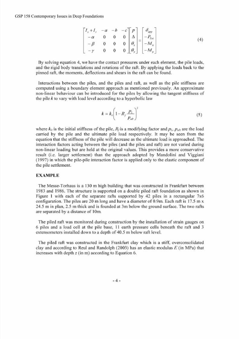
The finite element mesh for the twin rafts was made up of 8-noded isoparametric
elements and as can be seen in Figure 1, the two rafts were joined by a mesh of thin shell
elements. This is so the whole raft mesh can be analysed separately, and the connecting
elements were made very thin (0.05 m) so as to have negligible bending stiffness. They
therefore have very little effect on the solution.
Figure 1: Finite element mesh for the twin rafts of the Torhaus showing
instnunented pile locationsP1 to P6.
PLOT OF FINITE ELEMENT MES H
To allow for the fact that the raft was constructed 3 m deep, the load applied to thefoundation was taken as the applied load of 466.5 kPa minus the overburden pressure of
62.5 kPa (i.e. 404 kPa). This approach implies that during recompression of the
foundation, the clay will be very stiff and so its movement will be negligible.
35 0
- 30 0
. 50
20 0
-5 0
100
- 5 0
Sectn I
0 0 Sectn I1
- 4 0
303,
0 0 80 0 ma no 40 0
Gm P A m h a
AUWS 2 m
MU= TU~IMUSrlilrMurL
GSP 158 Contemporary Issues in Deep Foundations
8/6/2019 Non-Linear Analysis of Piled Raft Foundation - HG Poulos
http://slidepdf.com/reader/full/non-linear-analysis-of-piled-raft-foundation-hg-poulos 6/9
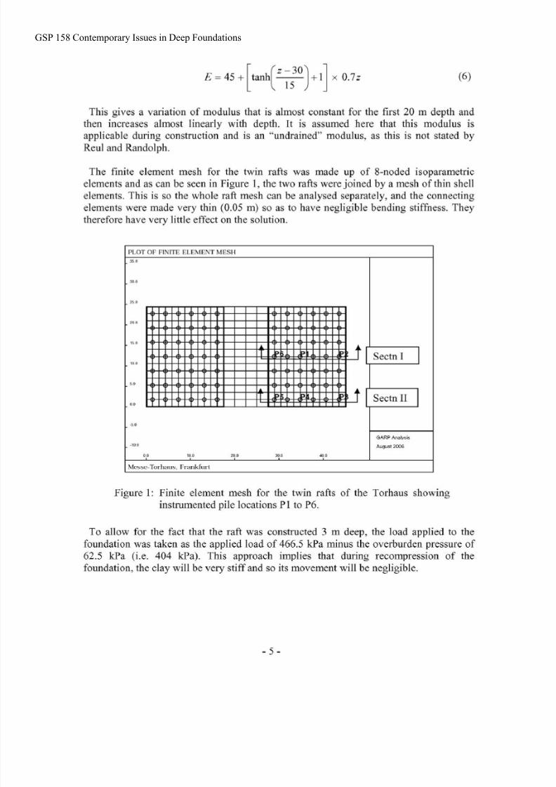
Pile 6 Pile 1 Pile 2
Figure 2: Pile loads for elastic analysis-Cross-section I.
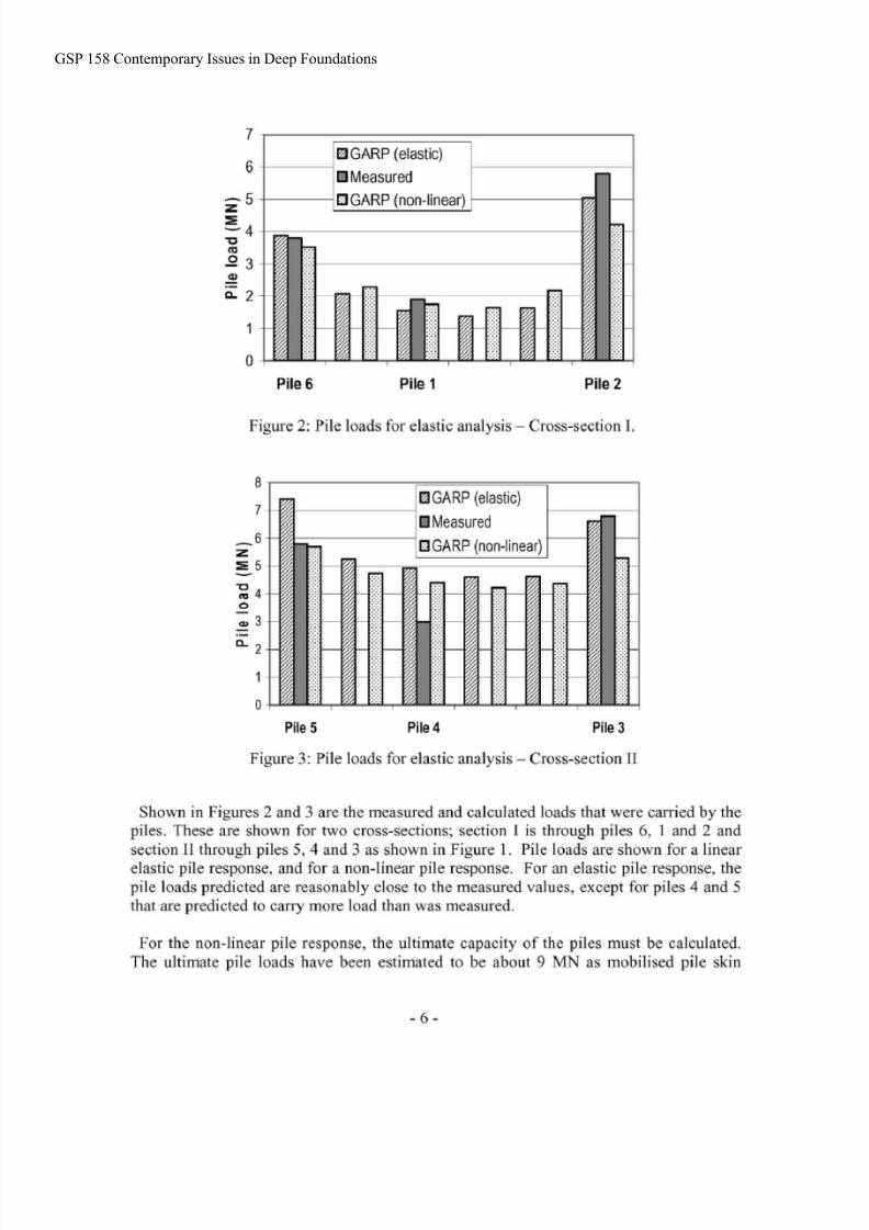
Pile 5 Pile 4 Pile 3
Figure 3: Pile loads for elastic analysis-Cross-section I1
Shown in Figures 2 and 3 are the measured and calculated loads that were carried by the
piles. These are shown for two cross-sections; section I is through piles 6, 1 and 2 andsection I1 through piles 5,4 and 3 as shown in Figure 1. Pile loads are shown for a linear
elastic pile response, and for a non-linear pile response. For an elastic pile response, thepile loads predicted are reasonably close to the measured values, except for piles 4 and 5
that are predicted to cany more load than was measured.
For the non-linear pile response, the ultimate capacity of the piles must be calculated.
The ultimate pile loads have been estimated to be about 9 MN as mobilised pile skin
GSP 158 Contemporary Issues in Deep Foundations
8/6/2019 Non-Linear Analysis of Piled Raft Foundation - HG Poulos
http://slidepdf.com/reader/full/non-linear-analysis-of-piled-raft-foundation-hg-poulos 7/9
frictions of the order of 140-150 kPa have been measured on piles in the Frankfurt clay,and as piles 3 and 2 were carrying loads of about 6 7 MN, the ultimate capacity of the
piles must have been at least this value . The pile head stiffness at the start of loading wascomputed to be 539 MN /m and the Rfvalue was chosen to be 0.5.
The effect of the non-linear pile response is to shed load from the m ore heavily loadedpiles to the more lightly loaded piles as they will have a stiffer response. However, thenon-linear analysis does not predict the high loads on the edge piles 2 and 3 as well as theelastic analysis but gives an improved prediction of the load on pile 5. This may be due tothe actual distribution of loading, as here the load was assumed to be uniformly applied.
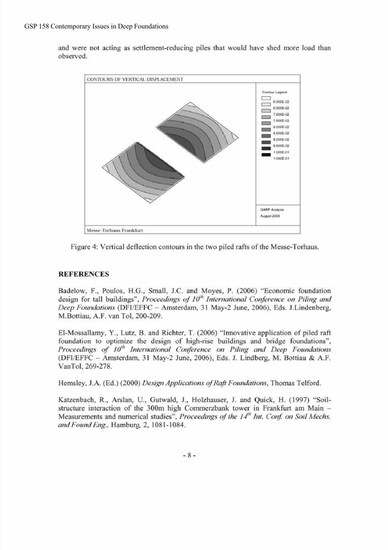
Deflection of the rafts is shown in Figure 4 where it may be seen that the twofoundations rotate toward s each other. The mean settlement of each raft calculated for anelastic response was about 80 mm whereas for the non-linear case it is slightly higher at85 mm. Th e measured settlements at the end of construction have been reported as 65 and80 mm at the centre of the northern and southern rafts respectively (Hemsley 2000).
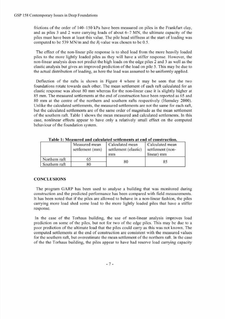
Unlike the ca lculated settlements, the measured settlements are not the sam e for each raft,but the calculated settlements are of the same order of magnitude as the mean settlementof the southern raft. Table 1 show s the mean m easured and calculated settlements. In thiscase, nonlinear effects appear to have only a relatively small effect on the computedbehaviour of the foundation system.
Table 1: Measured and calculated settlements at end of construction.
CONCLUSIONS
Measured meansettlement (mm )
Northern raftSouthern raft
The program GARP has been used to analyse a building that was monitored duringconstruction and the predicted performance has been compared with field measurements.It has been noted that if the piles are allowed to behave in a non-linear fashion, the pilescarrying more load shed some load to the more lightly loaded piles that have a stifferresponse.
In the case of the Torhaus building, the use of non-linear analysis improves loadprediction on some of the piles, but not for two of the edge piles. This may be due to apoor prediction of the ultimate load that the piles could carry as this was not known. Thecomputed settlements at the end of construction are consistent with the measured valuesfor the southern raft, but overestimate the mean settlement of the northern raft. In the caseof the the Torhaus building, the piles app ear to have had reserve load carrying capacity
Calculated meansettlement (elastic)
6580
Calculated meansettlement (non-
mm
80
linear)mm
85
GSP 158 Contemporary Issues in Deep Foundations
8/6/2019 Non-Linear Analysis of Piled Raft Foundation - HG Poulos
http://slidepdf.com/reader/full/non-linear-analysis-of-piled-raft-foundation-hg-poulos 8/9

8/6/2019 Non-Linear Analysis of Piled Raft Foundation - HG Poulos
http://slidepdf.com/reader/full/non-linear-analysis-of-piled-raft-foundation-hg-poulos 9/9
Kitiyodom, P. and Matsumoto, T. (2003) "A simplified analysis method for piled raftfoundations in non-homogeneous soils", Int. JZ. For Numerical Mefh. in Geomechs., 27,
Mandolini,A.
and Viggiani, C. (1997) "Settlement of piled foundations", Giotechniqrre,XLV II(4), 791-8 16.
Poulos, H.G. (199 4) "An approximate numerical analysis of pile-raft interaction", Znt. J1.for Nr~merical nd Analytical Meth0d.r in Geomechanics, 18(2), 73-92.
Poulos, H.G. & Davis, E.H. (1980) Pile foundation analysis anddesig n. John Wiley andSons, New York.
Reul, 0. Randolph, M. F. 2003. "Piled rafts in overconsolidated clay: comparison ofin-situ m easurements and numerical analyses", Giotechniqr~e,3(3), 301-315 .
Reul, 0.& Randolph, M. F. 2004. "Design strategies for piled rafts subjected tononuniform vertical loading", Jl. of Geotechnical and Geoenvironmental Eng., ASCE,130(1), 1-11
Small, J.C. and Zhang, H.H (2002) "Behaviour of piled raft foundations under lateral
and vertical loading", International Journal of Geomechanics, 2(1), 29-45.
Yamashita, K., Kakurai, M. and Yamada, T. (1993) "Settlement behaviour of five-storeybuilding on a piled raft foundation", Proceedings of the znd nt. Geotech. Seminar onDeep Foundations on Bored and Auger Piles - BAP II, Ghenf Belgium, W. Van Impe
(ed.), Balkema, Rotterdam, 35 1-356.
GSP 158 Contemporary Issues in Deep Foundations