Non-linear analysis of externally prestressed concrete beams · behavior of externally prestressed...
12
Electronic Journal of Structural Engineering, 2 (2002) http://www.ejse.org/ 2002 EJSE International. All rights reserved. 85 e e J J S S E E Non-linear analysis of externally prestressed concrete beams B.K. Diep and H. Umehara Department of Environmental Technology and Urban Planning Nagoya Institute of Technology, Nagoya, Japan Email: [email protected] ABSTRACT In an external prestressing system, there is no strain compatibility between the cable and the concrete at every cross-section, the increment of cable strain must be evaluated by taking into account the whole structure, rather than performing the calculation at each section, independently. In this study, a method for the calculation of cable strain, which is based on the deformation compatibility of beam and friction at the deviators, was proposed to predict entire response of externally prestressed concrete beams up to the ultimate state. Application of the developed method in numerical analysis of some examples was then performed. The predicted results showed that the structural behavior of externally prestressed concrete beams could be satisfactorily predicted from zero loading stage up to the ultimate loading stage. The proposed analysis reproduced experimental results such as deflection and increase of cable stress responses with remarkable accuracy. KEYWORDS Cable strain; external cable; unbonded; deviator; displacement 1. Introduction External prestressing is defined as prestress introduced by the high strength cable, which is placed outside the cross section and attached to the beam at some deviator points along the beam. The use of external prestressing is gaining popularity in bridge constructions because of its simplicity and cost-effectiveness. Moreover, the external prestressing is applied not only to new structures, but also to existing structures, which need to be repaired or strengthened. Although various advantages of external prestressing have been reported elsewhere [14], some questions concerning the behavior of externally prestressed concrete beams at ultimate are often arisen in the design practice. One of major problems concerning the beams prestressed with external cables is in calculating the cable stress beyond the effective prestress. In the case of beams prestressed with bonded cables, since the cable strain is assumed to be the same as the concrete strain at the cable level, the calculation of cable strain under the applied load is a problem related only to a section of maximum moment, i.e., the increase of cable strain is section-dependent. This is totally different in the case of beams prestressed with external cables. Since the cable is unbonded, the cable freely moves in the relation of beam deformation. Therefore, the cable strain is basically different from the concrete strain at every cross section, i.e., the cable strain cannot be determined from the local strain compatibility between the concrete and the cable. For the calculation of cable strain, it is necessary to formulate the global deformation compatibility of beam between the extreme ends. The strain variation in an external cable should be considered to be a function of the overall deformation of beam. This means that the strain change in the cable is member-dependent, and is influenced by the initial cable profile, span to depth ratio, deflected shape of the structure, friction at the deviators, the initial condition of beam, etc. [11]. This makes the analysis of a beam with external cables more complicated, and proper modeling of the overall deformation of beam becomes necessary.
Transcript of Non-linear analysis of externally prestressed concrete beams · behavior of externally prestressed...

Electronic Journal of Structural Engineering, 2 (2002) http://www.ejse.org/
2002 EJSE International. All rights reserved.
85eeJJSSEE
Non-linear analysis of externally prestressed concrete beams
B.K. Diep and H. Umehara
Department of Environmental Technology and Urban Planning Nagoya Institute of Technology, Nagoya, Japan
Email: [email protected]
ABSTRACT In an external prestressing system, there is no strain compatibility between the cable and the concrete at every cross-section, the increment of cable strain must be evaluated by taking into account the whole structure, rather than performing the calculation at each section, independently. In this study, a method for the calculation of cable strain, which is based on the deformation compatibility of beam and friction at the deviators, was proposed to predict entire response of externally prestressed concrete beams up to the ultimate state. Application of the developed method in numerical analysis of some examples was then performed. The predicted results showed that the structural behavior of externally prestressed concrete beams could be satisfactorily predicted from zero loading stage up to the ultimate loading stage. The proposed analysis reproduced experimental results such as deflection and increase of cable stress responses with remarkable accuracy. KEYWORDS Cable strain; external cable; unbonded; deviator; displacement
1. Introduction External prestressing is defined as prestress introduced by the high strength cable, which is placed outside the cross section and attached to the beam at some deviator points along the beam. The use of external prestressing is gaining popularity in bridge constructions because of its simplicity and cost-effectiveness. Moreover, the external prestressing is applied not only to new structures, but also to existing structures, which need to be repaired or strengthened. Although various advantages of external prestressing have been reported elsewhere [14], some questions concerning the behavior of externally prestressed concrete beams at ultimate are often arisen in the design practice. One of major problems concerning the beams prestressed with external cables is in calculating the cable stress beyond the effective prestress. In the case of beams prestressed with bonded cables, since the cable strain is assumed to be the same as the concrete strain at the cable level, the calculation of cable strain under the applied load is a problem related only to a section of maximum moment, i.e., the increase of cable strain is section-dependent. This is totally different in the case of beams prestressed with external cables. Since the cable is unbonded, the cable freely moves in the relation of beam deformation. Therefore, the cable strain is basically different from the concrete strain at every cross section, i.e., the cable strain cannot be determined from the local strain compatibility between the concrete and the cable. For the calculation of cable strain, it is necessary to formulate the global deformation compatibility of beam between the extreme ends. The strain variation in an external cable should be considered to be a function of the overall deformation of beam. This means that the strain change in the cable is member-dependent, and is influenced by the initial cable profile, span to depth ratio, deflected shape of the structure, friction at the deviators, the initial condition of beam, etc. [11]. This makes the analysis of a beam with external cables more complicated, and proper modeling of the overall deformation of beam becomes necessary.

Electronic Journal of Structural Engineering, 2 (2002) http://www.ejse.org/
2002 EJSE International. All rights reserved.
86eeJJSSEE
When the behavior of externally prestressed concrete beams was investigated, many researchers attempted to calculate the increase of cable stress beyond the effective prestress either by using their formulations with some parameters involved for the certain cases [6,8,9] or by using equations, which are provided in the codes for unbonded beams. While some researchers assumed that the strain variation in a cable is uniform over its entire length, and tried to calculate the cable strain by adopted assumption, which stated that the total elongation of a cable must be equal to the total elongation of concrete at the cable level [1,13]. Since the prestressing force transfers to the concrete beam through the deviator points and anchorage ends, the cable friction obviously exists at the deviators, resulting in a different level of strain increase between the two successive cable segments. However due to the complicated calculation of cable strain, almost all analytical approaches did not consider friction at the deviators into account because of its unknown extent. For simplicity in the calculation of cable strain, two extreme cases are usually considered, namely, free slip (no friction) and perfectly fixed (no movement) at the deviator. In the first case, the cable moves freely through the deviators without any restraint, and the cable is treated as an internally unbonded cable. The cable strain is assumed to be constant over its entire length regardless of the friction at the deviators. The increment of cable strain can be expressed as:
∫ ∆=∆l
css dxl 0
1 εε (1)
where ∆εs and ∆εcs are the increments of cable strain and concrete strain at the cable level, respectively; l is the total length of cable between the extreme ends. In the second case, the cable is considered perfectly fixed at the deviators, meaning that the strain variation for each segment is independent from the others. The increment of cable strain depends only on the deformations of two successive deviators or anchorages, at which the cable is attached. The strain variation can be expressed as:
i
isi l
l∆=∆ε
(2) where ∆li, li are the incremental and original lengths of the cable segment under consideration, respectively. For the former, if the frictional resistance at the deviators is neglected, deflection and cracking may be overestimated at the service loading range. For the latter, if the cable is assumed to be a perfectly fixed, the ultimate load capacity may be overestimated [11]. This phenomenon was also found in the analysis of three cases (free slip, slip with friction of 0.2 and perfectly fixed), which has been reported elsewhere [15]. Although an extensive body of experimental studies has been conducted to understand the behavior of externally prestressed concrete beams, a method of prediction, which gives results in close agreement with experimental observations, is still in research process. Nevertheless, the characteristic behavior of externally prestressed concrete beams at the ultimate state are a research topic, which has yet to be well understood in any depth. The demand for a better understanding of experimental observations has been an analytical research need. In this study, an analytical method was firstly proposed to predict entire response of externally prestressed concrete beams up to the ultimate state. The accuracy of proposed method was then verified by comparing the predicted results with experimental observations, which were presented at the end of this paper.

Electronic Journal of Structural Engineering, 2 (2002) http://www.ejse.org/
2002 EJSE International. All rights reserved.
87eeJJSSEE
2. Method of analysis 2.1 Non-linear analysis algorithm To obtain a whole deformed shape of beam, a finite element method is commonly used as one of powerful and popular tools in the structural analysis. The conventional finite element method often approximates a deformed shape of beam element with interpolation functions such as a cubic polynomial function for transverse displacement and a linear function for longitudinal displacement. The cubic function implies a linear variation of curvature along the element. However, the analysis of unbonded beams in general or the analysis of externally prestressed concrete beams in particular necessitates an accurate evaluation of strain variation in the concrete since the compatibility equation should be formulated with the values of concrete strain at the level of cable. Thus, a large number of short elements are necessary for the adequate evaluation of cable strain. In the previous study, a non-linear finite element program together with the displacement control method had been developed to obtain the entire behavior of externally prestressed concrete beams up to the ultimate limit state [3]. The program used a stepwise analysis and deformation control to trace the nonlinear response of prestressed concrete beams with external cables. The program is capable of accounting not only for the flexural deformation, but also for the shear deformation, friction at the deviators, and external cables with different configuration (straight or polygonal profile). In the analysis, the beam was represented by a set of beam elements connected together by nodes located at either end. Each node has three degrees of freedom, namely, horizontal displacement, vertical displacement and rotation. A cable stress equal to the effective stress after all losses, was taken as the initial value in the analysis. Cross section of the beam was divided into layers, in which each layer might have different materials, but its properties were assumed to be constant over the layer thickness. Based on the effective stress of cable, the concrete strain of each layer for every beam element was determined, and appeared to take as the initial condition of beam. In this study, the only one displacement control point, which could be arbitrarily chosen among the points of the applied load, was applied in the analysis. 2.2 Strain variation in external cables 2.2.1 Force equilibrium at a deviator Figure 1 showed that Fi, Fi+1 are tensile forces in the cable segments (i) and (i+1) at the deviator (i). Correspondingly, θi, θi+1 are cable angles, respectively. Thus, the force equilibrium condition on the X direction can be expressed as:
( ) 1111 cossinsin)1(cos ++++ =+−+ iiiiiik
ii FFFF i θθθµθ (3) where coefficient ki depends on the slipping direction, and has a value ki=1 if FicosθI > Fi+1cosθi+1 and ki=2 if Ficosθi < Fi+1cosθi+1; µ is the friction coefficient at the deviator. Eq.(3) can be rewritten in terms of incremental forces as:
( ) 1111 cossinsin)1(cos ++++ ∆=∆+∆−+∆ iiiiiik
ii FFFF i θθθµθ (4) where ∆Fi, ∆Fi+1 are the incremental forces at the both sides of deviator. Since the stress of an external cable usually remains below the elastic limit up to the failure of the beam, it is possible to rewrite the force equilibrium condition at the deviator in terms of the

Electronic Journal of Structural Engineering, 2 (2002) http://www.ejse.org/
2002 EJSE International. All rights reserved.
88eeJJSSEE
increments of cable strain by dividing both sides of Eq.(4) by EpsAps, the force equilibrium condition can be then expressed as:
( ) 1111 cossinsin)1(cos ++++ ∆=∆+∆−+∆ isiisiisik
isii θεθεθεµθε
Or
[ ] [ ] 0sin)1(cossin)1(cos 111 =∆−+−+∆−+ +++ sii
kisii
ki
ii εθµθεθµθ (5) where Eps and Aps are the elastic modulus and area of the cable; ∆εsi, ∆εsi+1 are the increments of cable strain at the both sides of deviator, respectively.
X
Y
iP
1=ik2=ik
iPµiθ
1+iFiF
1+iθ X
Y
iP
1=ik2=ik
iPµiθ
1+iFiF
1+iθ
Fig.1 - Force equilibrium at a deviator
2.2.2 Proposed equation for cable strain Since the deflection of external cable does not follow the beam deflection except at the deviator points during the beam is being deformed, the strain in a cable totally differs the strain in the concrete at the cable level. The strain induced in the concrete at the cable level varies according to the bending moment diagram, while the strain in an external cable is uniform over the length of cable segment between two successive deviators or anchorage end. The cable strain, therefore, cannot be determined from the local compatibility of deformation. An analytical model for externally prestressed concrete beams, therefore, should satisfy the total compatibility requirement, i.e., the total elongation of a cable must be equal to the integrated value of concrete deformation at the cable level. This requirement is commonly adopted elsewhere [3,4], and is referred to as “deformation compatibility of beam” in this study. The mathematical expression of the deformation compatibility of beam is expressed as:
∑ ∫
=
∆=∆n
i
l
cssii dxl1
0εε
(6) where ∆εsi is the increment of cable strain; li is the length of cable segment under consideration; ∆εcs is the increment of concrete strain at the cable level. Combining Eq.(6) with the force equilibrium condition at the deviator, which is expressed in Eq.(5), one can analytically obtain the increment of cable strain of each segment at the certain loading stage, and it can be expressed as the following:

Electronic Journal of Structural Engineering, 2 (2002) http://www.ejse.org/
2002 EJSE International. All rights reserved.
89eeJJSSEE
∆
=
∆∆
∆∆∆
−+−−+−+−
−+−−+−+−−+
∫
−
−−
−−
−
−−
−
00........00
....
....
)1()1(0)1(................0000
............000
............000
........................
........................
............)1()1(0
............0)1()1(
............0
1
3
2
1
11
11
1
3322
2211
321
11
2
22
11
l
cs
n
n
nk
nnk
n
nk
n
nn
kk
kkdx
SCSCSC
ll
SCSCSCSC
lll
nn
n
ε
εε
εεε
µµµ
µµµµ
Or
[ ]{ } [ ]{ }dNM s =∆ε (7) Finally, the increment of cable strain can be defined by using the inverse matrix operation as:
{ } [ ] [ ]{ } [ ]{ }dCdNMs ==∆ −1ε (8) where the letters Ci and Si are denoted as cosine and sine of the cable angle, and the subscripts under these letters indicate the cable angle number; {d} is the increment of nodal displacement vector. It can be seen from Eq.(7) that the strain variation in an external cable depends mainly on the overall deformation of the beam, friction at the deviators and cable angle. The increasing beam deformation under the applied load is in the relative change of cable elongation. The adequate evaluation of cable strain depends on the accurate extent in the calculation of concrete strain at the cable level. That is the strain variation in a cable depends on the displacement of every point of beam. Therefore, the concrete beam should be necessarily divided into a large number of short elements by using the finite element method. 3. Numerical analysis Using the proposed method, the behavior of the externally prestressed concrete beams with arbitrary loading conditions and different cross sectional shapes was investigated. The predicted results were then discussed and compared with experimental data to verify the accuracy of the developed method. The following assumptions are adopted in the analysis: 1. Plane sections remain plane after bending. 2. Shear deformations are considered. 3. The total requirement of deformation compatibility between the concrete and the cable is
that the total elongation of concrete elements at the cable level must be equal to the total elongation of cable elements between the extreme ends.
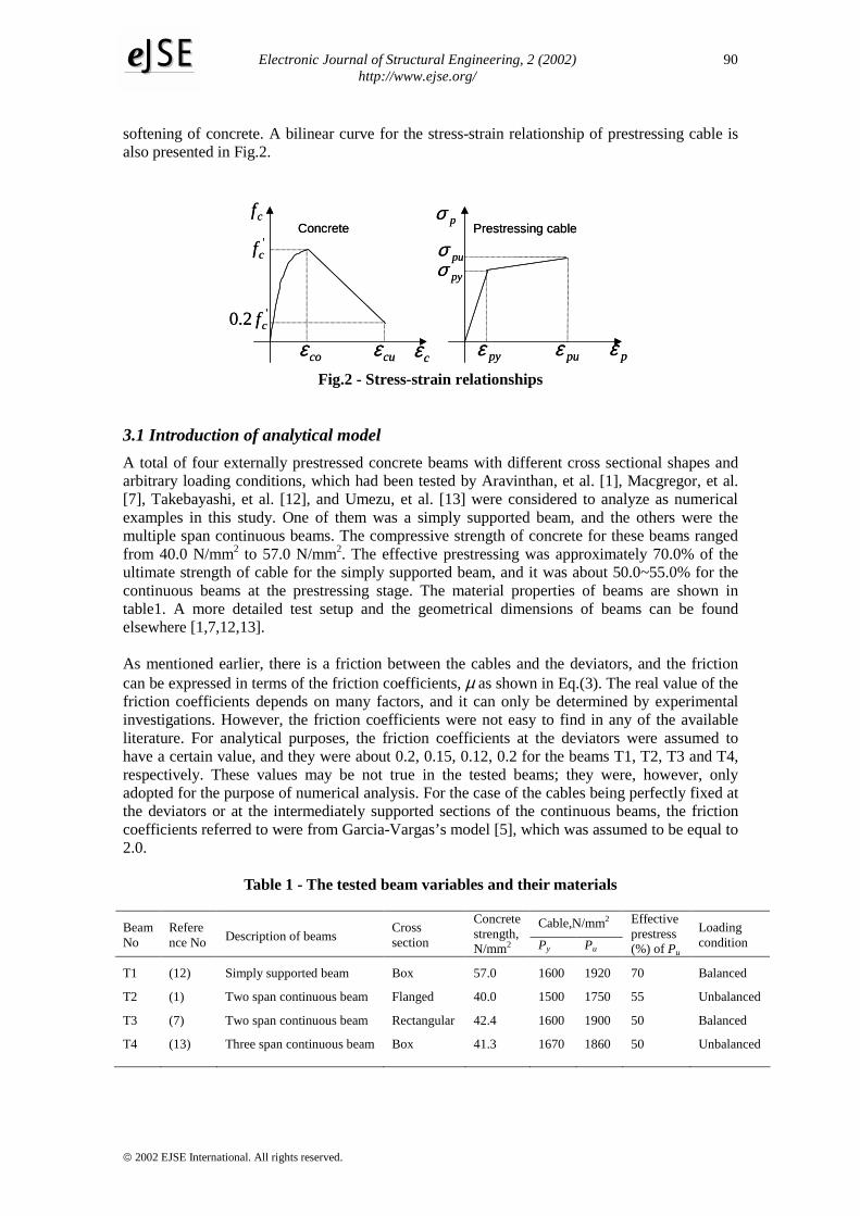
4. In the analysis, the stress-strain curve for the concrete in compression is assumed to be a parabolic ascending branch and a linear descending branch as shown in Fig.2. The stress-strain curve is expressed as follows:
−=
2' 2
co
c
co
ccc ff
εε
εε
for coc εε < (9) ( )coccc mff εε −−= 1
' for cucco εεε << (10)
where f’c is the compressive strength of concrete; εco is the concrete strain at the peak stress; εcu is the concrete strain at ultimate; m1=0.8f’c/(εcu-εco) is the post peak slope controlling the
Electronic Journal of Structural Engineering, 2 (2002) http://www.ejse.org/
2002 EJSE International. All rights reserved.
90eeJJSSEE
softening of concrete. A bilinear curve for the stress-strain relationship of prestressing cable is also presented in Fig.2.
'cf
coε cuε
pyσ
pyε puε
puσ
pσcfConcrete Prestressing cable
pεcε
'2.0 cf
'cf
coε cuε
pyσ
pyε puε
puσ
pσcfConcrete Prestressing cable
pεcε
'2.0 cf
Fig.2 - Stress-strain relationships
3.1 Introduction of analytical model A total of four externally prestressed concrete beams with different cross sectional shapes and arbitrary loading conditions, which had been tested by Aravinthan, et al. [1], Macgregor, et al. [7], Takebayashi, et al. [12], and Umezu, et al. [13] were considered to analyze as numerical examples in this study. One of them was a simply supported beam, and the others were the multiple span continuous beams. The compressive strength of concrete for these beams ranged from 40.0 N/mm2 to 57.0 N/mm2. The effective prestressing was approximately 70.0% of the ultimate strength of cable for the simply supported beam, and it was about 50.0~55.0% for the continuous beams at the prestressing stage. The material properties of beams are shown in table1. A more detailed test setup and the geometrical dimensions of beams can be found elsewhere [1,7,12,13]. As mentioned earlier, there is a friction between the cables and the deviators, and the friction can be expressed in terms of the friction coefficients, µ as shown in Eq.(3). The real value of the friction coefficients depends on many factors, and it can only be determined by experimental investigations. However, the friction coefficients were not easy to find in any of the available literature. For analytical purposes, the friction coefficients at the deviators were assumed to have a certain value, and they were about 0.2, 0.15, 0.12, 0.2 for the beams T1, T2, T3 and T4, respectively. These values may be not true in the tested beams; they were, however, only adopted for the purpose of numerical analysis. For the case of the cables being perfectly fixed at the deviators or at the intermediately supported sections of the continuous beams, the friction coefficients referred to were from Garcia-Vargas’s model [5], which was assumed to be equal to 2.0.
Table 1 - The tested beam variables and their materials
Cable,N/mm2 Beam No
Reference No Description of beams
Cross section
Concrete strength, N/mm2 Py Pu
Effective prestress (%) of Pu
Loading condition
T1
T2
T3
T4
(12)
(1)
(7)
(13)
Simply supported beam
Two span continuous beam
Two span continuous beam
Three span continuous beam
Box
Flanged
Rectangular
Box
57.0
40.0
42.4
41.3
1600
1500
1600
1670
1920
1750
1900
1860
70
55
50
50
Balanced
Unbalanced
Balanced
Unbalanced

Electronic Journal of Structural Engineering, 2 (2002) http://www.ejse.org/
2002 EJSE International. All rights reserved.
91eeJJSSEE
3.2 General discussions of analytical results Fig.3 through to Fig.6 represented the predicted characteristics of beams against the applied load in terms of load vs. deflection, load vs. increase of cable stress, etc. In these figures were also plotted the results obtained from the experimental observations in order to compare to the predicted ones. It can be seen from these figures that the behavioral responses were very well predicted in comparison with the experimental data. The load-displacement responses were satisfactorily obtained for the different cross sectional shapes, the arbitrary loading conditions and continuity of the structures (see Figs.3a, 4a, 5a, 6a). The load-displacement curves of all the beams were a close matching to the experimental data in the pre-peak loading range. In the post-peak loading range, the displacement responses of the beams T2 and T3 were shown well in comparison with the experimental data, while the post peak behaviors of the beams T1 and T4 cannot be compared with the experimental observations. Whether or not the post peak behaviors approximated the true phenomena, they were, however, not clear because the experimental data were not available. The distributions of moment and displacement along the beam length were well performed for the beams T2 and T4 with the unbalanced loading condition (see Figs.4c, 6b). The moment of midspan section on the left span of the beam T4 against the applied load, and the reactions at the supports are also presented in Figs.6c, 6d. Although a little discrepancy between the experimental data and the predicted results was observed, the precision of the analytical results was excellent, and the analytical method can accurately show the general behavior of prestressed concrete beams with external cables.
a) Load-displacement relationship b) Strain increase of the cable No.1
c) Strain increase of the concrete
Fig.3 - Behavioral characteristic of beam T1
0 0.0005 0.001 0.0015 0.0020
2.0
4.0
6.0
Mom
ent [
kN.m
]
Cable strain
x104
A1 A2
Cable No1A2
ExperimentalAnalytical
0 0.0005 0.001 0.0015 0.0020
2.0
4.0
6.0
Mom
ent [
kN.m
]
Cable strain
x104
A1 A2
Cable No1A2
ExperimentalAnalyticalExperimentalAnalytical
0 0.0005 0.001 0.0015 0.002 0.00250
2.0
4.0
6.0
Concrete strain
Mom
ent [
kN.m
]
x104
ExperimentalAnalytical
0 0.0005 0.001 0.0015 0.002 0.00250
2.0
4.0
6.0
Concrete strain
Mom
ent [
kN.m
]
x104
ExperimentalAnalyticalExperimentalAnalytical
0 0.1 0.2 0.3 0.4 0.50
2.0
4.0
6.0
Displacement [m]
Mom
ent [
kN.m
]
x104
ExperimentalAnalytical
0 0.1 0.2 0.3 0.4 0.50
2.0
4.0
6.0
Displacement [m]
Mom
ent [
kN.m
]
x104
ExperimentalAnalytical
0 0.1 0.2 0.3 0.4 0.50
2.0
4.0
6.0
Displacement [m]
Mom
ent [
kN.m
]
x104
ExperimentalAnalyticalExperimentalAnalytical

Electronic Journal of Structural Engineering, 2 (2002) http://www.ejse.org/
2002 EJSE International. All rights reserved.
92eeJJSSEE
The deformation of beams can be divided into two parts (the flexural deformation and the shear deformation). Figs.5a, 6a represented the shear deformations compared with the total deformation of beams T3 and T4. It can be seen that the shear deformations had an extremely small effect on the total deformation of beams in the non-cracked elastic region. However, the shear deformation increased very fast as the applied load increased after the decompression. It is shown from the analytical results that for the beams T2, T3, T4, the shear deformation approximately ranged from 4% to 17% of the total deformation of beam at the ultimate state. While, the beam T1 was the full-scale test of real structure, the shear deformation, therefore, had very little effect on the total deformation of beam even if the beam was near the stage of collapse. The increases in concrete strain of beams against the applied load are also presented in Figs.3c, 5c. Reasonable agreement between the predicted results and the experimental observations can be found. All the beams failed when the concrete was crushed at the extreme compression zone. The crushing of the concrete could be considered as a local failure of structures for the continuous beams. However, it was considered as a total collapse of structure for the simply supported beam. The same phenomena were also found in the experimental observations. As mentioned earlier, the strain variation in a cable depends on the overall deformation of beam and the cable friction at the deviators. Therefore, a little change in the deformed shape of beams is relative to the change of cable elongation. Figs 3b, 4b and 5b show the predicted results of
stress increase or strain increase in the cable against the applied load in comparison with the
a) Load-displacement relationship b) Increase of the cable stress
c) Distribution of the moment
Fig.4 - Behavioral characteristics of beam T2
0 100 200 300 4000
20
40
60
80
Cable stress [N/mm2]
Appl
ied
load
[kN
]
ExperimentalAnalytical
0 100 200 300 4000
20
40
60
80
Cable stress [N/mm2]
Appl
ied
load
[kN
]
0 100 200 300 4000
20
40
60
80
Cable stress [N/mm2]
Appl
ied
load
[kN
]
ExperimentalAnalyticalExperimentalAnalytical
0 2 4 6 8
-40
-20
0
20
40
60
Mom
ent [
kN.m
]
Beam length [m]
ExperimentalAnalytical
0 2 4 6 8
-40
-20
0
20
40
60
Mom
ent [
kN.m
]
Beam length [m]
ExperimentalAnalyticalExperimentalAnalytical
0 0.02 0.04 0.06 0.080
20
40
60
80
Displacement [m]
Appl
ied
load
[kN
]
Displacement on the right span
ExperimentalAnalytical
0 0.02 0.04 0.06 0.080
20
40
60
80
Displacement [m]
Appl
ied
load
[kN
]
Displacement on the right span
ExperimentalAnalytical
0 0.02 0.04 0.06 0.080
20
40
60
80
Displacement [m]
Appl
ied
load
[kN
]
Displacement on the right span
ExperimentalAnalyticalExperimentalAnalytical

Electronic Journal of Structural Engineering, 2 (2002) http://www.ejse.org/
2002 EJSE International. All rights reserved.
93eeJJSSEE
experimental data. It is apparently indicated from the analytical results that all the beams showed a small rate of stress increase in a cable in the non-cracked elastic region. The rate of stress increase, however, rapidly developed in the cracked inelastic region, i.e., the major part of stress increase occurred after the decompression of beam. It is also found that the cable stress increased more pronounced as the deflection of beam became large. This means that the stress increase in a cable was closely related to the beam deformation. It should be noted that the prestressing cable underwent a small stress variation for all the beams and remained in the elastic range up to the failure of beam. Although, the frictional resistance exists between the cable and the deviators, the strain variation in the cable with straight profile, however, was more or less equalized between the cable segments. The reason for this can be explained that a small friction force at the deviator points was induced by the straight cable, resulting the redistribution of cable strain was obviously taken place through the slippage. The analytical results also indicated that the straight cable had a small increase in the cable stress, whereas the shortly free length of cable had a great increase in the cable stress. The predicted results for that did not show herein for clarity. The predicted results of cable stress were reasonably agreed with the experimental data. For the two spans continuous beam T2, the prestressing cables continued from one end to the other end. Also the beam was applied by the unbalanced loading condition, i.e., the applied load on the right span was equal to 30 % of the applied load of the left span. Therefore, the prestressing cable tended to move from the right span to the left span through the center-
supported section. This means that the redistribution of cable strain was taken place through the slippage. Therefore, the stress in a cable increased only slowly so that when the crushing strain
a) Load-displacement relationship b) Increase of the cable stress
c) Strain increase of the concrete
Fig.5 - Behavioral characteristics of beam T3
0 100 200 300 400 5000
100
200
300
Cable stress [N/mm2]
Appl
ied
load
[kN
]
Crushing of concrete
ExperimentalAnalytical
0 100 200 300 400 5000
100
200
300
Cable stress [N/mm2]
Appl
ied
load
[kN
]
Crushing of concrete
ExperimentalAnalyticalExperimentalAnalytical
0 0.001 0.002 0.003 0.004 0.0050
100
200
300
App
lied
load
[kN
]
Concrete strain
ExperimentalAnalytical
0 0.001 0.002 0.003 0.004 0.0050
100
200
300
App
lied
load
[kN
]
Concrete strain
ExperimentalAnalyticalExperimentalAnalytical
0 0.02 0.04 0.06 0.080
100
200
300
Displacement [m]
App
lied
load
[kN
]
Shear displacement
Crushing of concrete
ExperimentalAnalytical
0 0.02 0.04 0.06 0.080
100
200
300
Displacement [m]
App
lied
load
[kN
]
Shear displacement
Crushing of concrete
ExperimentalAnalytical
0 0.02 0.04 0.06 0.080
100
200
300
Displacement [m]
App
lied
load
[kN
]
Shear displacement
Crushing of concrete
ExperimentalAnalyticalExperimentalAnalytical

Electronic Journal of Structural Engineering, 2 (2002) http://www.ejse.org/
2002 EJSE International. All rights reserved.
94eeJJSSEE
had been reached in the concrete, the stress in the cable was so far below its ultimate strength. When the concrete was suddenly crushed at the extreme compression zone, the cable stress sharply reduced as shown in the analytical results (Fig. 4b). The same phenomenon was also found in the experimental observation. However, the observed value still increased after the crushing of concrete, while the predicted result did not. Although the value of cable stress could not be properly predicted after the crushing of concrete, the analytical model, however, can predict the proper trend of stress increase in the cable up to the ultimate state.
While a comparison between the curves of load vs. deflection and load vs. increase of cable stress for the individual beam was made, it is interesting to note that these two curves are very similar in shape, indicating the close relationship between the deflection and the stress increase in the external cables. Consequently, the deformation compatibility of beam as mentioned earlier is verified to be suitable for the analysis of prestressed beams with external cables. A comparison between the predicted results and experimental data such as the ultimate load, the increase of cable stress and ultimate deflection is summarized in table 2. It can be concluded from this table that the predicted results were well agreed with the observed ones. The close agreement between the experimental data and the predicted results as stated above apparently indicates a feasibility and potential of the proposed method for the analysis of externally prestressed concrete beams.
a) Load-displacement relationship b) Distribution of the displacement
c) Moment vs. the applied load d) Reaction at the supports
Fig.6 - Behavioral characteristics of beam T4
0 10 20-0.06
-0.04
-0.02
0
Beam length [m]
Dis
plac
emen
t [m
]
0.015
5 15
ExperimentalAnalytical
0 10 20-0.06
-0.04
-0.02
0
Beam length [m]
Dis
plac
emen
t [m
]
0.015
5 15
ExperimentalAnalyticalExperimentalAnalytical
0 100 200 300 400
-400
-200
0
200
400
Applied load [kN]
Mom
ent [
kN.m
]
Moment atthe support NI
Moment at themidspan section
ExperimentalAnalytical
0 100 200 300 400
-400
-200
0
200
400
Applied load [kN]
Mom
ent [
kN.m
]
Moment atthe support NI
Moment at themidspan section
ExperimentalAnalyticalExperimentalAnalytical
0 100 200 300 400-200
0
200
400
Applied load [kN]
Rea
ctio
ns [k
N]
NE NI SI SE
NE
NI
SE
SIExperimentalAnalytical
0 100 200 300 400-200
0
200
400
Applied load [kN]
Rea
ctio
ns [k
N]
NE NI SI SE
NE
NI
SE
SIExperimentalAnalyticalExperimentalAnalytical
0 0.01 0.02 0.03 0.04 0.050
100
200
300
400
Displacement [m]
Appl
ied
load
[kn] Crushing
of concrete
ExperimentalAnalytical
Shear displacement
0 0.01 0.02 0.03 0.04 0.050
100
200
300
400
Displacement [m]
Appl
ied
load
[kn] Crushing
of concrete
ExperimentalAnalytical
Shear displacement
0 0.01 0.02 0.03 0.04 0.050
100
200
300
400
Displacement [m]
Appl
ied
load
[kn] Crushing
of concrete
ExperimentalAnalyticalExperimentalAnalytical
Shear displacement

Electronic Journal of Structural Engineering, 2 (2002) http://www.ejse.org/
2002 EJSE International. All rights reserved.
95eeJJSSEE
Table 2 - Summary of experimental data and analytical results
4. Conclusions Using a finite element algorithm including coupled effects of the shear deformation and the cable friction at the deviators performed a non-linear analysis of externally prestressed concrete beams. The strain variation in an external cable was investigated on the basis of the deformation compatibility of beam. The following conclusions can be made in this study: 1. The proposed method for the numerical analysis can satisfactorily predict the behavior of
externally prestressed concrete beams up to the ultimate loading stage. The predicted results in terms of load vs. deflection and load vs. increase of cable stress are in reasonably close agreement with the experimental data.
2. The stress increase in an external cable depends mainly on the overall deformation of beam and cable friction at the deviators. There is a close relationship between the two curves of load vs. deflection of load vs. increase of cable stress.
3. The proposed method is generally suitable for the investigation of all kinds of beam prestressed with external cables such as simply supported or multiple spans continuous beams with or without deviators. It should be noted that the proposed method might be a best performance for the research purpose rather than for the design practice.
REFERENCES 1 Aravinthan, T., Mutsuyoshi, H., Fujoka, A., Hishiki, Y., ”Flexural behavior of two span
continuous segmental prestressed concrete beams with external tendons”, Proceeding of JCI, 1996, Vol.18, No.2, pp.1121-1126.
2 Aravinthan, T., Mutsuyoshi, H., Niitsu, T., Chen, An., ”Flexural behavior of externally prestressed concrete beams with large eccentricities”, Proceeding of JCI, 1998, Vol.20, No.3, pp.673-678.
3 Diep, B.K, “Non Linear Analysis of externally prestressed concrete continuous beams considering shear deformation”, Master Thesis of Department of Civil Engineering-Nagoya University, 2000.
4 Diep, B.K., Tanabe, T., “Analysis of two continuous span prestressed concrete beam with external cables considering shear deformation”, Proceeding of JCI, 1999, Vol.21, No.3, pp.955-960.
5 Garcia-Vargas, J.A., Menezes, N, Trinh, J.L., “Effect of external tendon slipping at deviator on beam behaviour”, Proceeding of the Workshop on Behavior of External Prestressing in Structures, France, 1993, pp.227-237.
6 Lee, L.H., Moon, J.H., Lim, J.H., “Proposed methodology for computing of unbonded
Ultimate loads kN
Stress increase in cable N/mm2
Ultimate deflection mm
No Exp. Calc. Calc./Exp Exp. Calc. Calc./Ex Exp. Calc. Calc./Ex
T1
T2
T3
T4
58500*
73.3
308.0
375.0
58253*
72.0
310.8
377.0
0.996
0.982
1.009
1.005
0.0015**
230.0
370.0
319.0
0.0015**
185.0
366.0
307.0
1.000
0.804
0.989
0.962
350.0
50.0
48.0
40.6
358.0
48.0
50.2
40.3
1.023
0.960
1.045
0.993
* Applied moment (kN.m); ** Cable strain

Electronic Journal of Structural Engineering, 2 (2002) http://www.ejse.org/
2002 EJSE International. All rights reserved.
96eeJJSSEE
tendon stress at flexural failure”, ACI Structural Journal, Nov-Dec, 1999, pp 1040-1048. 7 Macgregor,.R.J.G., Kreger M.E., Breen J.E., “Strength and ductility of three span externally
post tensioned segmental box girder bridges model”, Proceeding of External Prestressing in Bridges, 1990, Sp120-15, pp.315-338.
8 Harajli, M.H., “Effect of span-depth ratio on the ultimate steel stress in unbonded prestressed concrete members”, ACI Structural Journal, May-June, 1990, pp.305-312.
9 Mutsuyoshi, H., Tsuchida, K., Matupayont, S., Machida, A., “Flexural behavior and proposal of design equation for flexural strength of externally prestressed concrete members”, JSCE Journal of Materials, Concrete Structures and Pavements, 1995, Vol.26, No.508, pp.67-77.
10 Paulo Chaves de Rezende-Martins, Paulo de Araujo Regis, Jean-Marie Desir, “A study on the behavior of hyperstatic concrete beams with mixed prestressing”, Proceeding of the Workshop on Behavior of External Prestressing in Structures, France, 1993, pp.217-226.
11 Rao P.S., Mathew, G., “Behavior of externally prestressed concrete beams with multiple deviators”, ACI Structural Journal, July-August 1996, pp.387-396.
12 Takebayashi, T., Deeprasertwong K., Leung Y.W., “A full scale destructive test of precast concrete segmental box girder bridge with external tendons and dry joints”, Proceeding of Institution Civil Engineering Structures & Buildings, 1994, No.104, pp.297-315.
13 Umezu, K., Fujita, M., Tamaki, K., Yamazaki J., “Study on ultimate flexural strength of two span continuous beams using external cables”, Proceeding of JCI, 1995, Vol.17, No.2, pp.743-748.
14 Virlogeux, M., “External prestressing”, Proceeding of IABSE, Zurich, Switzerland, 1982, 101-108.
15 Virlogeux, M., “Non linear analysis of externally prestressed structures”, Proceeding of FIP Symposium in Israel, 1988, pp.319-340.