NON-DESTRUCTIVE TESTING & MONITORING OF MASONRY...
10
10 th Canadian Masonry Symposium, Banff, Alberta, June 8 – 12, 2005 NON-DESTRUCTIVE TESTING & MONITORING OF MASONRY - NORTH AMERICAN CASE STUDIES R.G. Grieve 1 and P.A. Jeffs 2 1 President, Tekron Services Inc, 2543 Palisander Avenue, Mississauga, ON L5B 2L1; [email protected] 2 President, PJ Materials Consultants Limited, 11 Wagoners Trail, Guelph, ON, N1G 3M9; [email protected] ABSTRACT The investigation of deteriorated buildings and masonry structures without creating damage to the fabric can be a difficult task. The challenges facing the investigator often include learning sufficient information regarding the masonry assembly to reliably identify primary and contributory causes of damage, and how to evaluate the condition and extent of hidden masonry components. Without sufficient, meaningful information, the development of an effective restoration strategy can become extremely difficult and this often results in destructive evaluation methods being utilised, such as the extensive removal of exterior masonry units. Non-destructive testing (NDT) methods and computerised monitoring devices are now available that may be used to evaluate all types of buildings, including heritage structures and older masonry. This presentation provides a summary of a number of projects that used NDT and monitoring methods to assist in the effective development of restoration and conservation strategies. In particular, impact echo, ground penetrating radar and dynamic vibration response testing of stone, brick and concrete block masonry assemblies are demonstrated, together with selected examples of the data provided. The project examples include detecting voids and hidden damage within solid masonry, identifying damaged brick header units and delaminated dimension stone units, and determining the state of grouted cores within concrete block construction. Case studies will also be used to illustrate the use of monitoring devices to determine moisture-related conditions within masonry assemblies and the way in which the data can be used to determine the wetting/drying characteristics of the fabric. KEYWORDS: ground penetrating radar, impact-echo, vibration response, impulse response; non-destructive testing; moisture monitoring. INTRODUCTION When selecting an NDT investigation technique, a major problem is that there are currently few standard test methods available. This often causes owners or their engineers to disregard the benefits that can be achieved by specifying NDT techniques. Alternatively, it can promote the selection of techniques that may not be appropriate, often leading to the “it does not work syndrome”. Yet another complication is that it is seldom advisable to rely on one method to provide all the information that may be required for the investigation of a structure. Careful consideration of the structural materials, size of areas under investigation and their location can determine the selection of the most appropriate NDT methods with respect to cost and
Transcript of NON-DESTRUCTIVE TESTING & MONITORING OF MASONRY...
10th Canadian Masonry Symposium, Banff, Alberta, June 8 – 12, 2005
NON-DESTRUCTIVE TESTING & MONITORING OF MASONRY - NORTH AMERICAN CASE STUDIES
R.G. Grieve1 and P.A. Jeffs2
1President, Tekron Services Inc, 2543 Palisander Avenue, Mississauga, ON L5B 2L1; [email protected] 2President, PJ Materials Consultants Limited, 11 Wagoners Trail, Guelph, ON, N1G 3M9; [email protected]
ABSTRACT The investigation of deteriorated buildings and masonry structures without creating damage to the fabric can be a difficult task. The challenges facing the investigator often include learning sufficient information regarding the masonry assembly to reliably identify primary and contributory causes of damage, and how to evaluate the condition and extent of hidden masonry components. Without sufficient, meaningful information, the development of an effective restoration strategy can become extremely difficult and this often results in destructive evaluation methods being utilised, such as the extensive removal of exterior masonry units. Non-destructive testing (NDT) methods and computerised monitoring devices are now available that may be used to evaluate all types of buildings, including heritage structures and older masonry. This presentation provides a summary of a number of projects that used NDT and monitoring methods to assist in the effective development of restoration and conservation strategies. In particular, impact echo, ground penetrating radar and dynamic vibration response testing of stone, brick and concrete block masonry assemblies are demonstrated, together with selected examples of the data provided. The project examples include detecting voids and hidden damage within solid masonry, identifying damaged brick header units and delaminated dimension stone units, and determining the state of grouted cores within concrete block construction. Case studies will also be used to illustrate the use of monitoring devices to determine moisture-related conditions within masonry assemblies and the way in which the data can be used to determine the wetting/drying characteristics of the fabric. KEYWORDS: ground penetrating radar, impact-echo, vibration response, impulse response; non-destructive testing; moisture monitoring. INTRODUCTION When selecting an NDT investigation technique, a major problem is that there are currently few standard test methods available. This often causes owners or their engineers to disregard the benefits that can be achieved by specifying NDT techniques. Alternatively, it can promote the selection of techniques that may not be appropriate, often leading to the “it does not work syndrome”. Yet another complication is that it is seldom advisable to rely on one method to provide all the information that may be required for the investigation of a structure. Careful consideration of the structural materials, size of areas under investigation and their location can determine the selection of the most appropriate NDT methods with respect to cost and
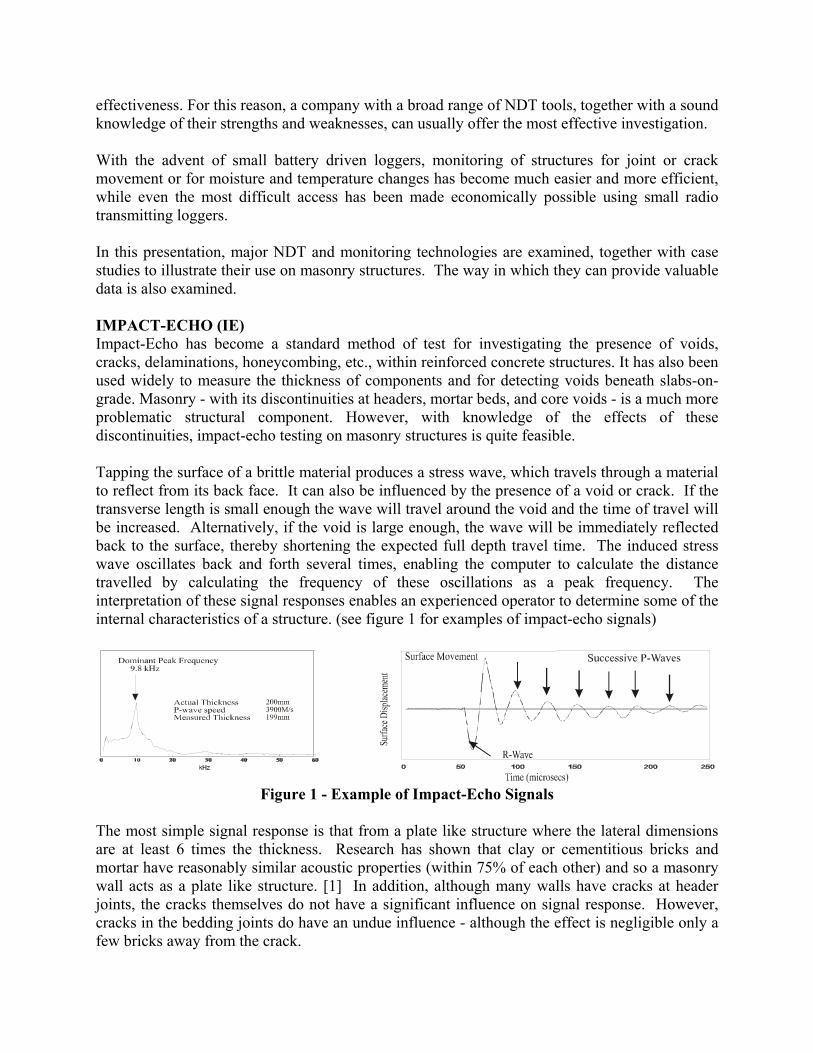
effectiveness. For this reason, a company with a broad range of NDT tools, together with a sound knowledge of their strengths and weaknesses, can usually offer the most effective investigation. With the advent of small battery driven loggers, monitoring of structures for joint or crack movement or for moisture and temperature changes has become much easier and more efficient, while even the most difficult access has been made economically possible using small radio transmitting loggers. In this presentation, major NDT and monitoring technologies are examined, together with case studies to illustrate their use on masonry structures. The way in which they can provide valuable data is also examined. IMPACT-ECHO (IE) Impact-Echo has become a standard method of test for investigating the presence of voids, cracks, delaminations, honeycombing, etc., within reinforced concrete structures. It has also been used widely to measure the thickness of components and for detecting voids beneath slabs-on-grade. Masonry - with its discontinuities at headers, mortar beds, and core voids - is a much more problematic structural component. However, with knowledge of the effects of these discontinuities, impact-echo testing on masonry structures is quite feasible. Tapping the surface of a brittle material produces a stress wave, which travels through a material to reflect from its back face. It can also be influenced by the presence of a void or crack. If the transverse length is small enough the wave will travel around the void and the time of travel will be increased. Alternatively, if the void is large enough, the wave will be immediately reflected back to the surface, thereby shortening the expected full depth travel time. The induced stress wave oscillates back and forth several times, enabling the computer to calculate the distance travelled by calculating the frequency of these oscillations as a peak frequency. The interpretation of these signal responses enables an experienced operator to determine some of the internal characteristics of a structure. (see figure 1 for examples of impact-echo signals)
Figure 1 - Example of Impact-Echo Signals
The most simple signal response is that from a plate like structure where the lateral dimensions are at least 6 times the thickness. Research has shown that clay or cementitious bricks and mortar have reasonably similar acoustic properties (within 75% of each other) and so a masonry wall acts as a plate like structure. [1] In addition, although many walls have cracks at header joints, the cracks themselves do not have a significant influence on signal response. However, cracks in the bedding joints do have an undue influence - although the effect is negligible only a few bricks away from the crack.
Most modern bricks have internal core voids, whereas prior to 1930 they were usually manufactured to be solid. Research has shown that these core voids have a significant but consistent effect on the signal response [1]. Depending on the volume of core voids, a shifted peak frequency (increased travel time) is caused which ranges from 26 to 30 percent. It is therefore important to establish the typical travel time through a selected brick removed from the wall under evaluation. Provided the above caveats are considered with respect to the signal response expected from a properly constructed multi-wythe masonry wall, it is possible to detect divergences from these responses and to identify the following masonry wall conditions:-
1. Voids in the grouted cells of reinforced concrete masonry unit assemblies. 2. Voids in the grouted cells of reinforced concrete masonry unit/brick veneer assemblies 3. Voids in the collar joint between reinforced concrete masonry unit/brick veneer
assemblies. 4. Voids in the joints between brick wythes in multi-wythe wall assemblies.
DYNAMIC VIBRATION RESPONSE (DVR) When testing a structural component for competency, it is natural to strike it with a hammer to determine whether or not any movement or vibration results. Using an instrumented hammer, an accelerometer and a laptop computer it is possible to advance this action into a scientific tool, whereby small differences in vibration response of a structural component can be detected. Compared to the impact-echo method, this test uses much greater force to cause localised movement of the component and much lower frequency sensors to capture the movement. The value of this technique is that it has a radius of influence of 1 - 1.5 m per blow and tests conducted in a grid pattern of this size can quickly encompass large areas of the structure. The resulting “mobility” survey highlights anomalies that can subsequently be examined in more detail using inspection openings or other non-destructive testing techniques, such as ground penetrating radar and impact-echo (discussed elsewhere). DVR is also referred to within the industry as impulse response (IR) [2]. Another use of DVR is the detection of differences - or excess movement - of external cladding and/or interior facia. The method can highlight locations where inadequate support is being provided due to deterioration of the wall anchoring systems. Additional applications for DVR include the detection of voids or weaknesses within masonry assemblies, such as collar joints and the inner core rubble of traditional mass masonry. Although DVR provides less detail, it facilitates rapid evaluation of large areas. Therefore it can be used to reveal anomalies within an expanse of masonry, which can be followed by more detailed testing using IE or ground penetrating radar methods.
GROUND PENETRATING RADAR (GPR) Ground Penetrating Radar has been used by the geotechnical industry for many years. However recent advances in this technology have extended its use into the field of masonry testing. The first advance was the development of commercial systems, which operated at wavelengths between 1000 and 1500 MHz, thereby providing the detail required for the examination of masonry structures and building envelopes. The second advance was the miniaturization of these systems, which permitted the system to be battery operated and housed in small handheld units. This allows them to be used in tight spaces with minimum set-up time and to be independent of the availability of power. The third advance was the development of standard PC programmes that can generate two and three-dimensional images of the data, thereby enabling complex GPR scans to be readily envisaged and presented to the non-expert user. GPR uses radio waves of similar frequency but significantly less strength than a cell phone. Therefore, unlike x-ray for example, its use does not provide a potential health hazard. The waves are pulsed one at a time from a transmitter to a receiver. An odometer wheel controls the pulse timing as the instrument is moved across the surface. The waves pass through masonry at speeds that depend on the electrical conductivity of the material under test. A higher strength reflection occurs when a wave meets a sudden boundary influenced by the presence of materials of significantly greater conductivities. The returning waves are stored electronically for future analysis and also displayed on a video screen, enabling the operator to detect the location and characteristics of embedded materials in real time, including metal, air, and water. A complete scan can consist of several thousand individual traces. Many scans taken in a precise pattern can be subjected to computer analysis to produce contour plots of two and three dimensional slices, thereby enabling visualization of the data at selected depths. GPR can be used on concrete structures to locate and quantify the presence of embedded materials such as reinforcing steel, post-tensioned cable, service pipes, etc., in addition to defects such as voids, and honeycombing. Although it is perfectly feasible to locate these same materials in masonry structures, it is much more common to use GPR to investigate the presence of voids or excessive moisture. MONITORING OF STRUCTURES When structural movement is measured, the first consideration should be the expected scale of the movement. This has a direct bearing on the accuracy of required reading. For example, joints can be expected to move significantly more than most cracks and therefore measurement of strain due to structural loading requires more accurate measurement for the latter. For this reason, a single system cannot always be used for all situations. One of the simplest movement monitoring systems uses small datum points fixed to the masonry. The relative movement is then measured using a sensitive dial gauge. Although the equipment cost is relatively inexpensive, data collection costs can be considerable. An alternative system has been developed which is significantly more accurate, can measure movement up to 5 mm (0.25 in) to an accuracy of 0.05 mm (0.0025 in) and has a built-in temperature-recording device.
It can store up to 8,000 readings taken at any selected time interval between ½ sec and 9 hours, thereby considerably reducing data collection costs. As crack movement is usually quite small, it requires sensitive instrumentation if the details of the displacement are to be recorded. In these instances, a vibrating wire system is a good choice, since there are a variety of different rugged and watertight sensors available. An additional advantage is that they can be monitored using either battery-operated single point loggers, or as data loggers with many channels.
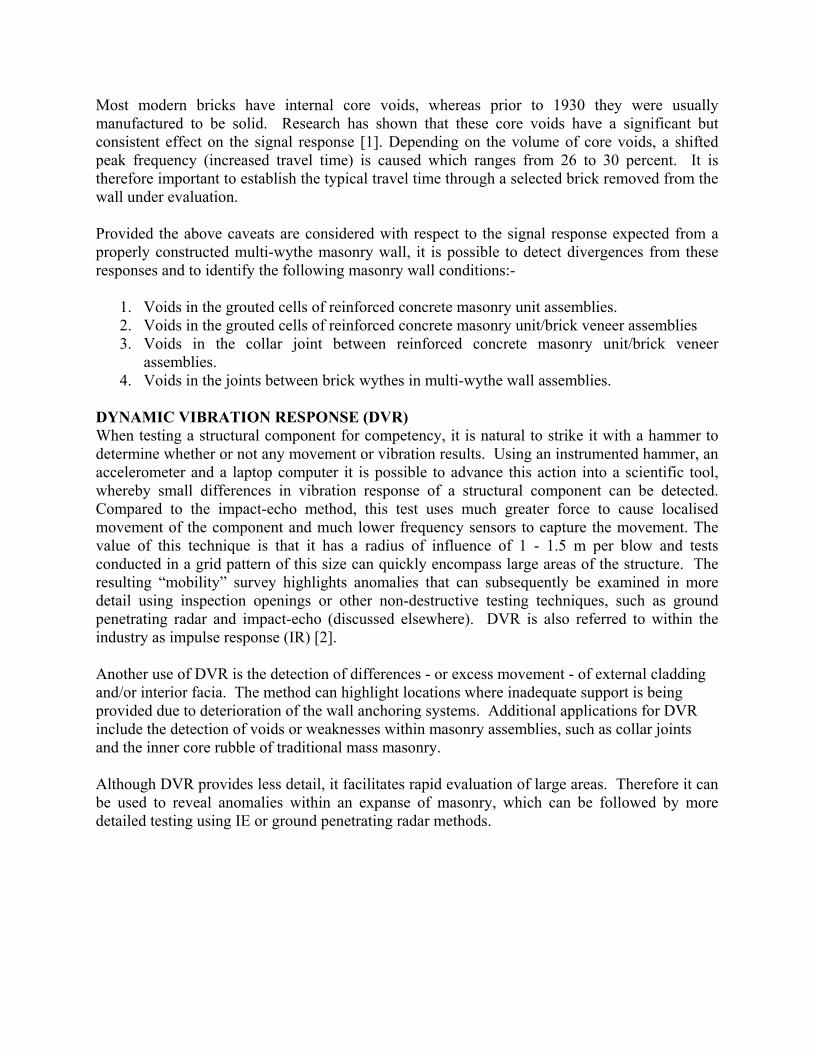
Figure 2 - Post Office Conversion - Impact-Echo Test Results
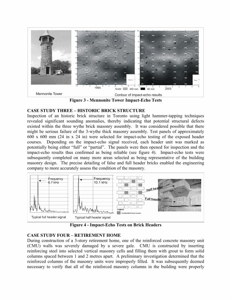
CASE STUDY ONE – POST OFFICE CONVERSION During conversion of an historic post office to a library, one of the limestone lintels split, crashing to the ground. Fortunately no one was hurt. Visual examination of the lintel determined that several pins installed into the top of each unit provided support. In this particular case, some of the pins had corroded, to cause the stone to split. After preliminary impact-echo tests on several whole and visually cracked lintels, it was determined that - although somewhat complicated - there were significant differences between signals induced within solid lintels compared to cracked lintels. Based on this preliminary work, every lintel was tested at each pin for the presence of cracking. This revealed that some of these remaining lintels were also cracked (see figure 2). CASE STUDY TWO – HISTORIC MONUMENT A Mennonite monument constructed in the early 1900’s as a cylindrical tower was badly deteriorating. The construction consisted of a stone exterior wythe with an unreinforced concrete backup. Degradation of the concrete surface was visible on the interior and several cores confirmed deterioration of the interface between the facing stone and concrete. In 1995, it was decided to evaluate the extent of this interface deterioration using impact-echo tests. The tests revealed that the deterioration was quite extensive, particularly around the bottom of the monument. Subsequent impact-echo testing in 2000 and 2005 revealed that the inner deterioration of the monument was accelerating and this information was sufficient to initiate a repair programme (see figure 3).
450 mm 90 mmScale
Mennonite Tower Contour of impact-echo results
1995 2003
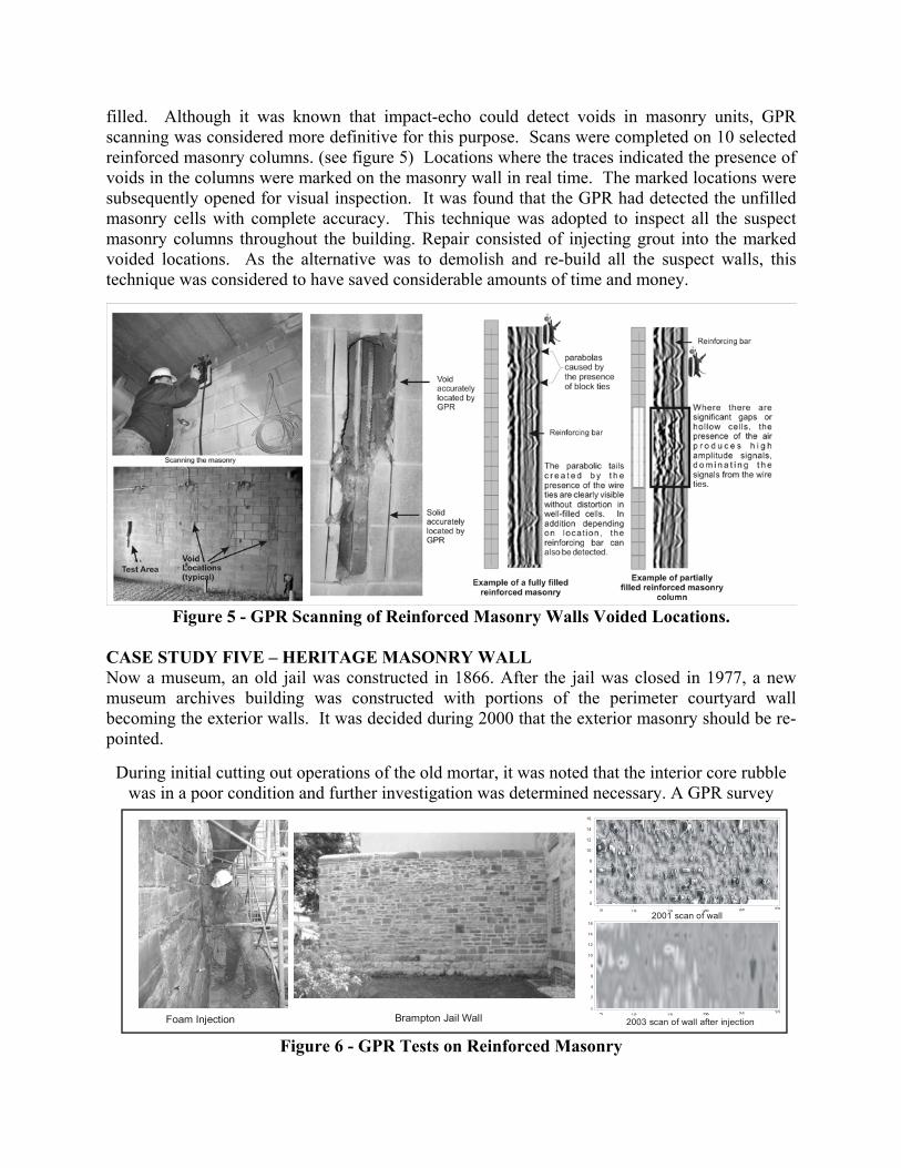
Figure 3 - Mennonite Tower Impact-Echo Tests CASE STUDY THREE – HISTORIC BRICK STRUCTURE Inspection of an historic brick structure in Toronto using light hammer-tapping techniques revealed significant sounding anomalies, thereby indicating that potential structural defects existed within the three wythe brick masonry assembly. It was considered possible that there might be serious failure of the 3-wythe thick masonry assembly. Test panels of approximately 600 x 600 mm (24 in x 24 in) were selected for impact-echo testing of the exposed header courses. Depending on the impact-echo signal received, each header unit was marked as potentially being either “full” or “partial”. The panels were then opened for inspection and the impact-echo results thus confirmed as being reliable (see figure 4). Impact-echo tests were subsequently completed on many more areas selected as being representative of the building masonry design. The precise detailing of false and full header bricks enabled the engineering company to more accurately assess the condition of the masonry.
Figure 4 - Impact-Echo Tests on Brick Headers
CASE STUDY FOUR – RETIREMENT HOME During construction of a 3-story retirement home, one of the reinforced concrete masonry unit (CMU) walls was severely damaged by a severe gale. CMU is constructed by inserting reinforcing steel into selected vertical masonry cells and filling them with grout to form solid columns spaced between 1 and 2 metres apart. A preliminary investigation determined that the reinforced columns of the masonry units were improperly filled. It was subsequently deemed necessary to verify that all of the reinforced masonry columns in the building were properly
16
14
12
10
8
6
4
2
2001 scan of wall
2003 scan of wall after injection
16
14
12
10
8
6
4
2
0
Foam Injection Brampton Jail Wall
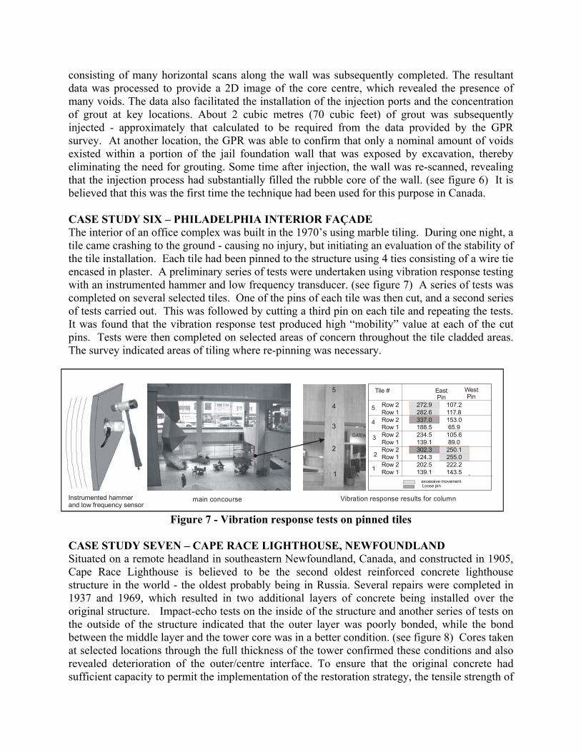
filled. Although it was known that impact-echo could detect voids in masonry units, GPR scanning was considered more definitive for this purpose. Scans were completed on 10 selected reinforced masonry columns. (see figure 5) Locations where the traces indicated the presence of voids in the columns were marked on the masonry wall in real time. The marked locations were subsequently opened for visual inspection. It was found that the GPR had detected the unfilled masonry cells with complete accuracy. This technique was adopted to inspect all the suspect masonry columns throughout the building. Repair consisted of injecting grout into the marked voided locations. As the alternative was to demolish and re-build all the suspect walls, this technique was considered to have saved considerable amounts of time and money.
Figure 5 - GPR Scanning of Reinforced Masonry Walls Voided Locations.
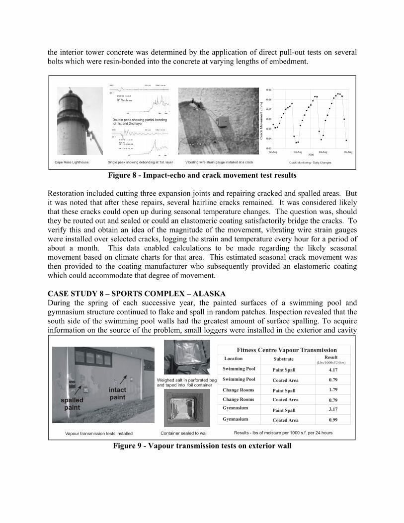
CASE STUDY FIVE – HERITAGE MASONRY WALL Now a museum, an old jail was constructed in 1866. After the jail was closed in 1977, a new museum archives building was constructed with portions of the perimeter courtyard wall becoming the exterior walls. It was decided during 2000 that the exterior masonry should be re-pointed.
During initial cutting out operations of the old mortar, it was noted that the interior core rubble was in a poor condition and further investigation was determined necessary. A GPR survey
Figure 6 - GPR Tests on Reinforced Masonry
consisting of many horizontal scans along the wall was subsequently completed. The resultant data was processed to provide a 2D image of the core centre, which revealed the presence of many voids. The data also facilitated the installation of the injection ports and the concentration of grout at key locations. About 2 cubic metres (70 cubic feet) of grout was subsequently injected - approximately that calculated to be required from the data provided by the GPR survey. At another location, the GPR was able to confirm that only a nominal amount of voids existed within a portion of the jail foundation wall that was exposed by excavation, thereby eliminating the need for grouting. Some time after injection, the wall was re-scanned, revealing that the injection process had substantially filled the rubble core of the wall. (see figure 6) It is believed that this was the first time the technique had been used for this purpose in Canada. CASE STUDY SIX – PHILADELPHIA INTERIOR FAÇADE The interior of an office complex was built in the 1970’s using marble tiling. During one night, a tile came crashing to the ground - causing no injury, but initiating an evaluation of the stability of the tile installation. Each tile had been pinned to the structure using 4 ties consisting of a wire tie encased in plaster. A preliminary series of tests were undertaken using vibration response testing with an instrumented hammer and low frequency transducer. (see figure 7) A series of tests was completed on several selected tiles. One of the pins of each tile was then cut, and a second series of tests carried out. This was followed by cutting a third pin on each tile and repeating the tests. It was found that the vibration response test produced high “mobility” value at each of the cut pins. Tests were then completed on selected areas of concern throughout the tile cladded areas. The survey indicated areas of tiling where re-pinning was necessary.
Figure 7 - Vibration response tests on pinned tiles CASE STUDY SEVEN – CAPE RACE LIGHTHOUSE, NEWFOUNDLAND Situated on a remote headland in southeastern Newfoundland, Canada, and constructed in 1905, Cape Race Lighthouse is believed to be the second oldest reinforced concrete lighthouse structure in the world - the oldest probably being in Russia. Several repairs were completed in 1937 and 1969, which resulted in two additional layers of concrete being installed over the original structure. Impact-echo tests on the inside of the structure and another series of tests on the outside of the structure indicated that the outer layer was poorly bonded, while the bond between the middle layer and the tower core was in a better condition. (see figure 8) Cores taken at selected locations through the full thickness of the tower confirmed these conditions and also revealed deterioration of the outer/centre interface. To ensure that the original concrete had sufficient capacity to permit the implementation of the restoration strategy, the tensile strength of
107.2272.9Row 2117.8282.6Row 1153.0337.0Row 265.9188.5Row 1105.6234.5Row 289.0139.1Row 1250.1302.3Row 2255.0124.3Row 1222.2202.5Row 2143.5139.1Row 11
2
3
4
5
Tile # EastPin
WestPin
excessive movementLoose pin
Instrumented hammerand low frequency sensor
1
2
3
4
5
main concourse Vibration response results for column
the interior tower concrete was determined by the application of direct pull-out tests on several bolts which were resin-bonded into the concrete at varying lengths of embedment.
Cape Race Lighthouse
Double peak showing partial bonding of 1st and 2nd layer
Single peak showing debonding at 1st. layer Vibrating wire strain gauge installed at a crack
Figure 8 - Impact-echo and crack movement test results
Restoration included cutting three expansion joints and repairing cracked and spalled areas. But it was noted that after these repairs, several hairline cracks remained. It was considered likely that these cracks could open up during seasonal temperature changes. The question was, should they be routed out and sealed or could an elastomeric coating satisfactorily bridge the cracks. To verify this and obtain an idea of the magnitude of the movement, vibrating wire strain gauges were installed over selected cracks, logging the strain and temperature every hour for a period of about a month. This data enabled calculations to be made regarding the likely seasonal movement based on climate charts for that area. This estimated seasonal crack movement was then provided to the coating manufacturer who subsequently provided an elastomeric coating which could accommodate that degree of movement. CASE STUDY 8 – SPORTS COMPLEX – ALASKA During the spring of each successive year, the painted surfaces of a swimming pool and gymnasium structure continued to flake and spall in random patches. Inspection revealed that the south side of the swimming pool walls had the greatest amount of surface spalling. To acquire information on the source of the problem, small loggers were installed in the exterior and cavity
Location Substrate Result(Lbs/1000sf/24hrs)
Swimming Pool
Swimming Pool
Change Rooms
Change Rooms
Gymnasium
Gymnasium
Fitness Centre Vapour Transmission
Paint Spall
Coated Area
Paint Spall
Paint Spall
Coated Area
Coated Area
4.17
0.79
1.79
0.79
0.99
3.17
spalledpaint
intactpaint
Vapour transmission tests installed
Weighed salt in perforated bagand taped into foil container
Container sealed to wall Results - lbs of moisture per 1000 s.f. per 24 hours
Figure 9 - Vapour transmission tests on exterior wall
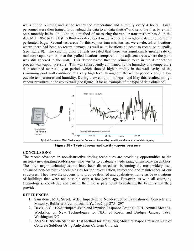
walls of the building and set to record the temperature and humidity every 4 hours. Local personnel were then trained to download the data to a “data shuttle” and send the files by e-mail on a monthly basis. In addition, a method of measuring the vapour transmission based on the ASTM F 1869 [ref 3] test method was developed using accurately weighed calcium chloride in perforated bags. Several test areas for this vapour transmission test were selected at locations where there had been no recent damage, as well as at locations adjacent to recent paint spalls. (see figure 9). The calcium chloride tests revealed that there was significantly greater rate of moisture vapour emission at the spalled locations compared to the adjacent areas where the paint was still adhered to the wall. This demonstrated that the primary force in the deterioration process was vapour pressure. This was subsequently confirmed by the humidity and temperature data obtained over a 1 year period, which showed high humidity in the wall cavity of the swimming pool wall continued at a very high level throughout the winter period - despite low outside temperatures and humidity. During thaw condition of April and May this resulted in high vapour pressures in the cavity wall (see figure 10 for an example of the type of data obtained)
Humidity &TemperatureLogger
Typical Room and Wall Cavity Vapour Pressure obtained by humidity and temperature data logging
0.0
0.5
1.0
1.5
2.0
2.5
24-Apr 14-May 24-May 3-Jun 23-Jun
Vapo
ur P
ress
ure
Room vapour pressure
External (wall cavity vapour pressure)
Figure 10 - Typical room and cavity vapour pressure
CONCLUSIONS The recent advances in non-destructive testing techniques are providing opportunities to the masonry investigating professional who wishes to evaluate a wide range of masonry assemblies. The three major technologies that have been discussed are becoming the most widely used advanced non-destructive technologies for the investigation, restoration and maintenance of our structures. They have the propensity to provide detailed and qualitative, non-evasive evaluations of buildings that were not possible even a few years ago. However, as with all emerging technologies, knowledge and care in their use is paramount to realizing the benefits that they provide. REFERENCES
1. Sansalone, M.J., Street, W.B., Impact-Echo Nondestructive Evaluation of Concrete and Masonry, Bullbrier Press, Ithaca, N.Y., 1997, pp 275 - 297
2. Davis, A.G., 1998. “Impact-Echo and Impulse Response Testing”. TRB Annual Meeting. Workshop on New Technologies for NDT of Roads and Bridges January 1998, Washington DC
3. ASTM F1869-04 Standard Test Method for Measuring Moisture Vapor Emission Rate of Concrete Subfloor Using Anhydrous Calcium Chloride