
non-destructive testing and assessment of dynamic incompatibility ...
19
NON-DESTRUCTIVE TESTING AND ASSESSMENT OF DYNAMIC INCOMPATIBILITY BETWEEN 3 rd PARTY PIPING AND DRAIN VALVE SYSTEMS: AN INDUSTRIAL CASE STUDY Siamak Noroozi a , Abdul Ghaffar Abdul Rahman b , Eng Hoe Cheng c , Mihai Dupac a ∗ , Ong Zhi Chao d , Khoo Shin Yee d , Kong Keen Kuan d , John E Vinney a a School of Design, Engineering and Computing, Bournemouth University, Talbot Campus, Fern Barrow, Poole, Dorset, BH12 5BB, UK b Mechanical Engineering Faculty, Universiti Malaysia Pahang, 26600 Pekan, Malaysia c Quadrant 2 Technologies Sdn. Bhd., Kuala Lumpur, Malaysia d Department of Mechanical Engineering, University of Malaya, 50603 Kuala Lumpur, Malaysia ∗ Corresponding author: Mihai Dupac, School of Design, Engineering and Computing, Bournemouth University, Poole, Dorset, BH12 5BB, UK, E-mail: [email protected] Provide short biographical notes on all contributors here if the journal requires them.
Transcript of non-destructive testing and assessment of dynamic incompatibility ...
NON-DESTRUCTIVE TESTING AND ASSESSMENT OF
DYNAMIC INCOMPATIBILITY BETWEEN 3rd PARTY PIPING
AND DRAIN VALVE SYSTEMS: AN INDUSTRIAL CASE STUDY
Siamak Noroozia, Abdul Ghaffar Abdul Rahmanb, Eng Hoe Chengc , Mihai
Dupaca∗ , Ong Zhi Chaod, Khoo Shin Yeed, Kong Keen Kuand, John E
Vinneya
aSchool of Design, Engineering and Computing, Bournemouth University, Talbot
Campus, Fern Barrow, Poole, Dorset, BH12 5BB, UK
bMechanical Engineering Faculty, Universiti Malaysia Pahang, 26600 Pekan, Malaysia
cQuadrant 2 Technologies Sdn. Bhd., Kuala Lumpur, Malaysia
dDepartment of Mechanical Engineering, University of Malaya, 50603 Kuala Lumpur,
Malaysia
∗ Corresponding author: Mihai Dupac, School of Design, Engineering and Computing,
Bournemouth University, Poole, Dorset, BH12 5BB, UK, E-mail:
Provide short biographical notes on all contributors here if the journal requires them.
Non-destructive Testing and Assessment of Dynamic Incompatibility
between 3rd Party Piping and Drain Valve Systems: An Industrial Case
Study
This paper presents the outcome of an industrial case study that involved
condition monitoring of piping system that showed signs of excess fatigue due to
flow induced vibration. Due to operational requirements a novel non-destructive
assessment stratagem was adopted using different vibration analysis techniques –
such as Experimental Modal Analysis (EMA) and Operating Deflection Shapes
(ODS) – and complemented by visual inspection. Modal analysis performed near
a drain valve showed a dynamic weakness problem (several high frequency flow
induced vibration frequency peaks) hence Condition Based Monitoring (CBM)
was used.This could easily be linked to design problem associated with the
dynamic incompatibility due to dissimilar stiffness between two 3rd party
supplied pipe and valve systems. It was concluded that this is the main cause for
these problem types especially when systems are supplied by third parties, but
assembled locally, a major cause of dynamic incompatibility. It is the local
assembler’s responsibility to develop skills and expertise needed to sustain the
operation of these plants. This paper shows the technique used as result of one
such initiative. Since high amplitude, low frequency displacement can cause low
cycle fatigue, attention must be paid to ensure flow remains as steady-state as
possible. The ability to assess the level of design incompatibility and the level of
modification required using non-destructive testing is vital if these systems are to
work continuously.
Keywords: modal analysis; non-destructive testing; ODS; pipe; stress; vibrations
1. Introduction
Vibration loading, typically mechanical or flow-induced, is the most common
cause of high cycle fatigue [1]. In a recent survey [2] pipe cracking was identified as the
most frequently recurring problem, the most significant cause of which was determined
to be piping vibration. Mechanical vibration was one of the major causes of all
reportable occurrences involving pipes and fittings [2]. Failure of piping systems can
have disastrous effects, leading to injuries and even fatalities as well as creating a
substantial additional cost to industry and the environment. Piping vibration problems in
operating plants have resulted in costly unscheduled outages [3]. Piping vibration
failures have been one of the major causes of downtime, fires and explosions in
industrial plant over the past 30 years. For example, one piping failure at a
petrochemical plant in 1974 caused over $114,000,000 in property damage due to an
explosion [4]. In nuclear pressurised water reactor power plants, over 80 cases of cracks
or leaks occurred in the piping systems of charging pumps over a two year period [5].
Therefore, it is vitally important that piping vibration amplitudes in a system be
evaluated to determine if the levels are acceptable. If the vibrations levels are judged to
be excessive, the piping configuration, support structure, span length or material may
have to be modified to make the system acceptable [6-8].
Detecting, monitoring and predicting vibration [9] is an important and cost
effective way to identify issues associated with structures such as general wear and tear,
possible imbalance problems or incompatible structural stiffness. However, vibration
monitoring can only pinpoint the root causes of failures which are usually triggered by
poor design, poor assembly, miss-alignment or imbalance of whole structure of
associated components. This incompatible structural stiffness is usually due to the
presence of sub-optimal structures that lacks dynamic compatibility due to non-uniform
mass distribution or miss-match stiffness such as fluid momentum greater than the
stiffness of the pipe. In such cases, the overall dynamic response is no longer the
expected one and the system behaves in a completely different or unpredictable manner.
One of the main causes of the unpredictable behaviour of pipes is the induced
vibrations due to the interaction between the structure (walls of the pipe as well as the
pipe supports) and the fluid flowing through the pipe. Generally the fluid behaves as a
turbulent flow and exerts random pressures on the pipe walls [10]. Due to the fluid
structure interaction including flow turbulent fluctuations and unsteady pressure on the
pipe walls a random response will be induced to the pipe structure which may result in
resonant vibrations. The pipe response can be unstable undergoing large structural
vibrations once a critical threshold value is exceeded by the turbulent flow. It has been
proved that the fluid-structure interaction phenomenon induces a significant response of
the structure [11] and alters the fluid force acting on the walls. The fluid-induced
vibration of simply supported and clamped pipelines was studied in [12], where
parameters such as liquid mass density to pipe-wall mass density ratio, pipe radius to
pipe-wall thickness ratio, fluid velocity and fluid pressure are considered. A vibration
analysis of a 3-dimensional piping system composed of curved and straight sections is
performed in [13] using the wave approach while the obtained results are compared
with the ones obtained from a FEM formulation.
Other causes of the unpredictable behaviour of pipes is the fluid high internal
velocity which can induce buckling on a pipe supported at both ends and high instability
at on a pipe supported at one end. A structured and systematic assessment approach of
the vibration of pipes was considered in [14]. The study conveys that some of main
problems in the existing vibrating piping systems are due to poor supporting systems.
The general stability problem of vibrating pipes conveying fluid has been
studied extensively in [10] and [15]. The nonlinear dynamics of a pulsatile pipe
conveying fluid was studied in [16] while the nonlinear dynamics of a curved pipe
conveying fluid subject harmonic excitation was studied in [17].
The phase shift effects of resonant vibrating pipes due to various imperfections
are discussed in [18, 19] and their dynamic structural response in [20]. The perturbation
analysis used provides direct insight into how the non-uniform mass, stiffness, the non-
proportional damping, or weak imperfections affect the phase shift. The post-buckling
effect in vibrating pipes which permit axial sliding and don’t deflect transversely was
discussed in [21]. Traditionally, modal parameters, such the ones presented above, are
extracted by conducting experimental modal analysis on a static pipe structure.
However sometimes extracting modal parameters while the system is in operation is
highly desirable. A method named Operational Modal Analysis (OMA) has been
introduced in order analyse structures subjected to excitation generated by their own
operation [22]. System identification methods are efficient OMA tools to estimate
modal parameters from ambient vibrations. A review of in operation identification for
modal analysis that is Stochastic System Identification (SSI) has been fully reviewed in
[40]. The method described in [23] was successfully used to identify damages during
the operation of the pipes of a gas compressor due to operating equipment as well as the
flowing fluid. When classical condition monitoring is not possible, in-service Operating
Deflection Shape (ODS), a non-invasive and non-destructive approach to monitor and
visualise the motion of the system while in operation [24-29], can be successfully used.
To assess possible structural damage, fatigue crack initiation, growth behavior
and resistance of cracked pipes under cyclic loading have been studied in [30]. A failure
analysis of a hydraulic pipe due to resonance condition as a form of energy dissipation
resulting from viscous friction has been presented in [31], where a crack structural
damage was assessed due to the corrosion of the pipe and the reach of maximal
admissible stress. A failure analysis of a natural gas pipe adjacent to a source of
vibration, based on pipe material characterisation, dynamic stress, modal analysis and
metallurgical assessment was studied in [32]. The main factor leading to failure (a crack
was initiated) was considered the huge energy level due to an increase in the amplitude
of a vibrating valve leading to the development of the pipe dynamic stress.
This paper presents the outcome of an industrial case study that involved
condition monitoring of a piping system that showed signs of excess fatigue due to flow
induced vibration. Due to operational requirement a novel non-destructive assessment
stratagem was adopted using different vibration analysis techniques – such as
Experimental Modal Analysis (EMA) and Operation Deflection Shapes (ODS) – and
complemented by visual inspection. Modal analysis performed near a drain valve
showed a dynamics weakness problem (several high frequency flow induced vibration
frequency peaks) hence initiated Condition Based Monitoring (CBM). The analysis
reveals a dynamic weakness problem of a drain valve along the piping system, due to a
design problem and dynamic incompatibility of the supplied pipe and valve systems.
This could easily be linked to design problem associated with the dynamic
incompatibility due to dissimilar stiffness between two 3rd party supplied pipe and
valve systems. It was concluded that this is the main cause for these types problem
especially when systems are supplied by third parties and assembled locally.
2. Problem Formulation
Condition monitoring of an industrial piping system shown in Figure 1 is considered in
this section. Due to the operational requirements, a non-destructive assessment
stratagem to carry out a vibration diagnostic & analysis was considered using the
Experimental Modal Analysis (EMA) and Operating Deflection Shapes (ODS) analysis
techniques described below.
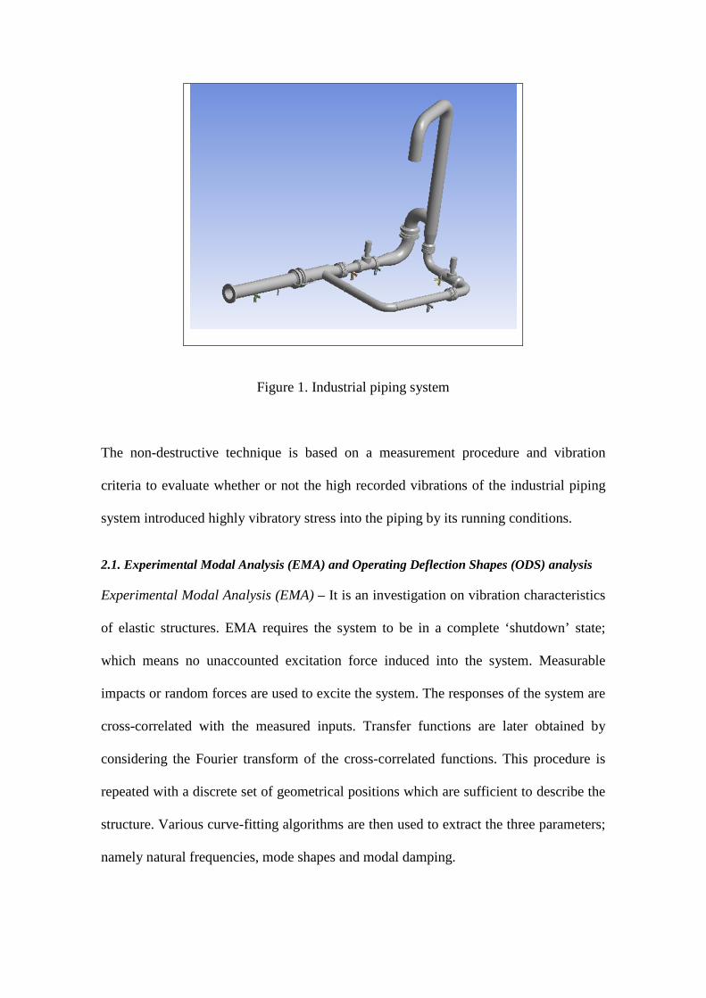
Figure 1. Industrial piping system
The non-destructive technique is based on a measurement procedure and vibration
criteria to evaluate whether or not the high recorded vibrations of the industrial piping
system introduced highly vibratory stress into the piping by its running conditions.
2.1. Experimental Modal Analysis (EMA) and Operating Deflection Shapes (ODS) analysis
Experimental Modal Analysis (EMA) – It is an investigation on vibration characteristics
of elastic structures. EMA requires the system to be in a complete ‘shutdown’ state;
which means no unaccounted excitation force induced into the system. Measurable
impacts or random forces are used to excite the system. The responses of the system are
cross-correlated with the measured inputs. Transfer functions are later obtained by
considering the Fourier transform of the cross-correlated functions. This procedure is
repeated with a discrete set of geometrical positions which are sufficient to describe the
structure. Various curve-fitting algorithms are then used to extract the three parameters;
namely natural frequencies, mode shapes and modal damping.
EMA with SISO, SIMO and MIMO modal identification algorithms in time, frequency
and spatial domain, has been widely used in troubleshooting, Structural Dynamic
Modification (SDM), analytical model updating, optimal dynamic design, passive and
active vibration control, as well as vibration-based structural health monitoring in
aerospace, mechanical and civil engineering. In applications, the extracted modal
parameters from EMA have been widely used to detect damage on beams and beam-like
structures [33-37] as well as rotor systems [38, 39]. These are the methods used for
damage detection based on dynamic characteristics of structures such as natural
frequencies, dynamic mode shapes, and structural damping. These methods have taken
advantage of the present day development of modal analysis techniques with accurate
measurements of modal parameters. When damage event occurs, the structural dynamic
characteristics changes and this may be used as an indicator of damage.
Operating Deflection Shapes (ODS) analysis – A very attractive solution named
Operating Deflection Shape (ODS) can measure the deflection of structures while in-
service. Generally, an operating deflection shape can be defined as “any forced motion
of two or more points on a structure”[24] and can be planar, orbital or three dimensional.
Since ODS represents a linear combination of the mode shapes of a structure, ODS
measurement should be performed under constant and stable operating conditions in
order to obtain accurate results. The measurement should be performed in such a way so
the measurement equipment does not affect the answer of the system, that is, a high
signal to noise ratio. In the measurement process the constant and stable operating
condition depends on the system complexity and whether all DOFs are measured
simultaneous or not, while the “simultaneous” condition depends on the number of data
acquisition channels and DOFs to be measured.

There are basically three types of operating deflection shape named Time ODS
which measures the vibration of a structure as a function of time, or Spectral ODS and
Run-up/down ODS which measure the vibration pattern of an equipment (typically a
rotating machinery) at a discrete operating frequency. For a pipe operating structure
when no rotating equipment is employed along the pipe, the measured time signal
obtained from the ODS can be processed to show the pipe behavior over time.
2.2. Measurement procedure description
A non-invasive measurement and evaluation procedure applied to a piping system that
showed signs of excess fatigue was considered based on the “need to know” whether or
not and how the stress induced into the piping by its running conditions, i.e. flow
induced high amplitude vibrations, affect the overall structural integrity of the piping
system. The measurement and evaluation procedure have been devised using a state of
the art MDT-Q2 data acquisition system based on a 4 channels real-time machinery
analyser, tri-axial (measurement locations were taken in the principal directions) and
uni-axis accelerometers, modally tuned impact hammer and related equipment and
ME’scope software used to analyse the motion and the excessive vibration levels of the
piping system. It has been observed that the flow induced vibrations may not cause
excessive stresses in the main pipe but to the adjacent systems that are attached to the
vibrating pipe.

Figure 2. Allowable Piping Vibration Level versus Frequency
As a part of the non-invasive measurement and evaluation procedure, the evaluation
part has been based on the allowable levels of piping vibration versus the associated
frequencies criteria shown in Figure 2. The criteria states that for the cases when piping
vibration amplitudes at the measured frequencies are greater than the danger line (the
red line in Figure 2) then piping failures are considered to be typical occurrences, and
for the cases when the vibration level were below the design line (blue line shown in
Figure 2), very few failures may occur. It was considered that vibrations level versus
frequency criteria can serve as a good starting point in assessing piping vibrations and
to screen systems that need further analysis [7].
3. Results
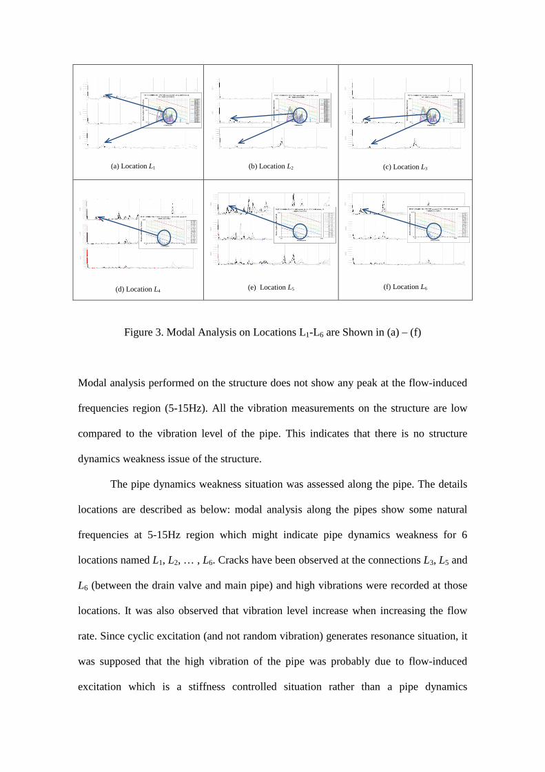
Modal analysis was performed during non-operating condition to obtain the natural
frequencies of industrial piping system and structure. Figure 3 show the results for
different locations.
(a) Location L1
(b) Location L2
(c) Location L3
(d) Location L4
(e) Location L5
(f) Location L6
Figure 3. Modal Analysis on Locations L1-L6 are Shown in (a) – (f)
Modal analysis performed on the structure does not show any peak at the flow-induced
frequencies region (5-15Hz). All the vibration measurements on the structure are low
compared to the vibration level of the pipe. This indicates that there is no structure
dynamics weakness issue of the structure.
The pipe dynamics weakness situation was assessed along the pipe. The details
locations are described as below: modal analysis along the pipes show some natural
frequencies at 5-15Hz region which might indicate pipe dynamics weakness for 6
locations named L1, L2, … , L6. Cracks have been observed at the connections L3, L5 and
L6 (between the drain valve and main pipe) and high vibrations were recorded at those
locations. It was also observed that vibration level increase when increasing the flow
rate. Since cyclic excitation (and not random vibration) generates resonance situation, it
was supposed that the high vibration of the pipe was probably due to flow-induced
excitation which is a stiffness controlled situation rather than a pipe dynamics
weakness. As a result is was concluded that the high vibration of the pipe are probably
due to the process and design problem.
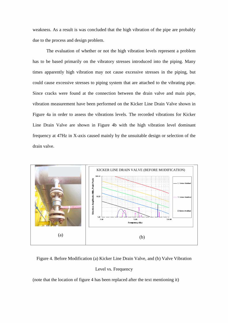
The evaluation of whether or not the high vibration levels represent a problem
has to be based primarily on the vibratory stresses introduced into the piping. Many
times apparently high vibration may not cause excessive stresses in the piping, but
could cause excessive stresses to piping system that are attached to the vibrating pipe.
Since cracks were found at the connection between the drain valve and main pipe,
vibration measurement have been performed on the Kicker Line Drain Valve shown in
Figure 4a in order to assess the vibrations levels. The recorded vibrations for Kicker
Line Drain Valve are shown in Figure 4b with the high vibration level dominant
frequency at 47Hz in X-axis caused mainly by the unsuitable design or selection of the
drain valve.
(a)
(b)
Figure 4. Before Modification (a) Kicker Line Drain Valve, and (b) Valve Vibration
Level vs. Frequency
(note that the location of figure 4 has been replaced after the text mentioning it)
KICKER LINE DRAIN VALVE (BEFORE MODIFICATION)
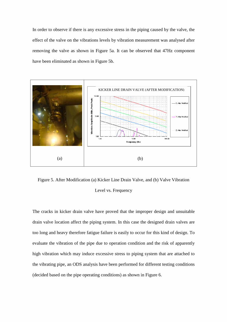
In order to observe if there is any excessive stress in the piping caused by the valve, the
effect of the valve on the vibrations levels by vibration measurement was analysed after
removing the valve as shown in Figure 5a. It can be observed that 47Hz component
have been eliminated as shown in Figure 5b.
(a)
(b)
Figure 5. After Modification (a) Kicker Line Drain Valve, and (b) Valve Vibration
Level vs. Frequency
The cracks in kicker drain valve have proved that the improper design and unsuitable
drain valve location affect the piping system. In this case the designed drain valves are
too long and heavy therefore fatigue failure is easily to occur for this kind of design. To
evaluate the vibration of the pipe due to operation condition and the risk of apparently
high vibration which may induce excessive stress to piping system that are attached to
the vibrating pipe, an ODS analysis have been performed for different testing conditions
(decided based on the pipe operating conditions) as shown in Figure 6.
KICKER LINE DRAIN VALVE (AFTER MODIFICATION)
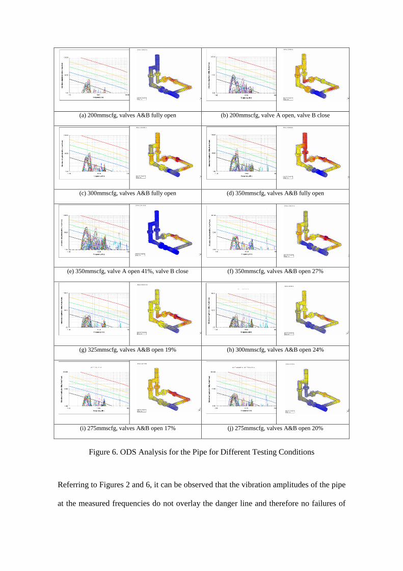
(a) 200mmscfg, valves A&B fully open (b) 200mmscfg, valve A open, valve B close
(c) 300mmscfg, valves A&B fully open (d) 350mmscfg, valves A&B fully open
(e) 350mmscfg, valve A open 41%, valve B close (f) 350mmscfg, valves A&B open 27%
(g) 325mmscfg, valves A&B open 19% (h) 300mmscfg, valves A&B open 24%
(i) 275mmscfg, valves A&B open 17% (j) 275mmscfg, valves A&B open 20%
Figure 6. ODS Analysis for the Pipe for Different Testing Conditions
Referring to Figures 2 and 6, it can be observed that the vibration amplitudes of the pipe
at the measured frequencies do not overlay the danger line and therefore no failures of
the pipe are expected. However, two vibration tests performed at a maximal flow rate
(350mmscfd) show highest vibration levels for the pipe and a possible contribution in
increasing the levels of stress to piping system that are attached to the vibrating pipe,
especially when, as resulting from the modal analyses, these system which are supplied
by third parties and assembled locally, suffer from dynamic incompatibility. Therefore,
these vibrations versus frequency criteria can serve as a good starting point in
evaluating piping vibrations in screening those systems that need further analysis.
4. Conclusions
In this paper an investigation into the application of non-destructive evaluation of in-
service pipe has been presented. The modal analyses applied to the piping structure do
not show any indication of a structural dynamics weakness issue. Modal analysis along
the pipes show there are few natural frequencies at 5-15Hz region which may be an
indication of the pipes dynamics weakness. Some of the modal analyses which have
been performed near a drain valve showed a design problem due to dissimilar stiffness –
dynamic incompatibility - between the supplied pipe and valve systems.
It was concluded that this was the main cause for these types of problem
especially when these systems are supplied by third parties, but assembled locally.
Moreover, since the high vibration response of the pipe was mainly due to the flow-
induced excitation as shown by the ODS analysis, a combined further analysis on the
pipe design and flow (including a dynamical stress analysis and fluid-structure
interaction (FSI)) is needed in order to (a) understand the process flow inside the pipe,
(b) understand the flow-induced vibration/stresses for the entire system, (c) optimise
piping production, and (d) to run the system under allowable endurance stress limit and
safe condition.
References
[1] Agency, O. N. E.: Nuclear Power Plant Operating Experiences from the IAEA/NEA Incident
Reporting System 2002-2005. 2006, 1-56
[2] Kustu, O., & Scholl, R.: Research Needs for Resolving the Significant Problems of Light-Water
Reactor Piping Systems. 1980
[3] Olson, D. E.: Pipe Vibration Testing and Analysis Companion Guide to the ASME Boiler & Pressure
Vessel Code (Vol. Chapter 37). New York: ASME PRESS, 2002
[4] Garison. W.G.: Major Fires and Explosions Analyzed for 30-Year Period, Hydrocarbon Processing,
1988
[5] Olson, D. E.: Piping Vibration Experience in Power Plants, Pressure Vessel and Piping Technology,
A Decade of Progress, Book No. H0030, ASME, 1985
[6] Wachel, J.C., Morton, S.J., and Atkins, K. E.: Piping Vibration Analysis, 19th Turbomachinery
Symposium, Texas A&M University, September, 1990.
[7] Wachel, J.C., Piping Vibration and Stress, Vibration Institute, Machinery Vibration Monitoring and
Analysis Seminar, New Prleans, LA, April, 1981, 1-20
[8] Wachel, J.C., “Displacement Method For Determining Acceptable Piping Vibration Amplitudes”,
PVP-Vol. 313-2, International Pressure Vessels and Piping Codes and Standards: Volume 2, ASME,
1995.
[9] Rao S.S.: Mechanical Vibration, SI Edition, Prentice Hall, 2005.
[10] Blevins R.D.: Flow induced vibration. 2nd ed. New York: Van Nostrand Reinhold, 1990. Chen S.S.:
Flow-induced vibration of circular cylindrical structures, Washington: Hemisphere Publishing
Corporation, 1987.
[11] Dai H.L., Wang L., Qian Q., Gan J.: Vibration analysis of three-dimensional pipes conveying fluid
with consideration of steady combined force by transfer matrix method, Applied Mathematics and
Computation (Article in Press)
[12] Zou G.P., Cheraghi N., Taheri F., Fluid-induced vibration of composite natural gas pipelines,
International Journal of Solids and Structures 42, 2005, 1253–1268
[13] Koo G.H., Park Y.S.: Vibration analysis of a 3-dimensional piping system conveying fluid by wave
approach, International Journal of Pressure Vessels and Piping 67, 1996, 249-256.
[14] Sukaih N.: A practical, systematic and structured approach to piping vibration assessment,
International Journal of Pressure Vessels and Piping 79, 2002, 597–609
[15] Chen S.S.: Flow-induced vibration of circular cylindrical structures, Washington: Hemisphere
Publishing Corporation, 1987.
[16] Panda L.N., Kar R.C.: Nonlinear dynamics of a pipe conveying pulsating fluid with combination,
principal parametric and internal resonances, Journal of Sound and Vibration 309, 2008, 375–406
[17] Lin W., Qiao N., Yuying H., Dynamical behaviours of a fluid-conveying curved pipe subjected to
motion constraints and harmonic excitation, Journal of Sound and Vibration 306, 2007, 955–967
[18] Enz S., Thomsen J.J.: Predicting phase shift effects for vibrating fluid-conveying pipes due to
Coriolis forces and fluid pulsation, Journal of Sound and Vibration 330, 2011, 5096–5113
[19] Thomsen J. J., Dahl J.: Analytical predictions for vibration phase shifts along fluid-conveying pipes
due to Coriolis forces and imperfections, Journal of Sound and Vibration 329, 2010, 3065–3081
[20] Semke W.H., Bibel G.D., Jerath S., Gurav S.B., Webster A.L.: Efficient dynamic structural response
modelling of bolted flange piping systems, International Journal of Pressure Vessels and Piping 83,
2006, 767–776
[21] Plaut R.H.: Postbuckling and vibration of end-supported elastica pipes conveying fluid and columns
under follower loads, Journal of Sound and Vibration 289, 2006, 264–277
[22] Mohanty P., Rixen D.J.: A modified Ibrahim time domain algorithm for operational modal analysis
including harmonic excitation, Journal of Sound and Vibration 275(1–2), 2004, 375–390.
[23] Trebuňa F., Šimčák F., Huňady R., Pástor M., Identification of pipes damages on gas compressor
stations by modal analysis methods, Engineering Failure Analysis, 27, 2013, 213–224
[24] Devriendt C., Steenackers G., DeSitter G., Guillaume P.: From operating deflection shapes towards
mode shapes using transmissibility measurements, Mechanical Systems and Signal Processing, 24,
2010, 665-677
[25] Dossing O., Staker C.H.: Operational deflection shapes: background, measurement and applications,
5th International Modal Analysis Conference, London, UK, 1987, 1372–1378.
[26] Marscher W.D.: Jen C.W.: Use of operating deflection and mode shapes for machinery diagnostics,
Proceedings of 17th International Modal Analysis Conference, 1999, 65–71.
[27] McHargue P.L., Richardson M.H.: Operating detection shapes from time versus frequency domain
measurements, The 11th International Modal Analysis Conference, Kissimmee, USA, 1993, 581-587.
[28] Pascual R., Golinval J.C., Razeto M.: On-line damage assessment using operating detection shapes,
Proceedings of 17th International Modal Analysis Conference, 1999. 238–243.
[29] Tongue B.H.: Principles of Vibration, Oxford University Press, 2nd ed., 2002.
[30] Singha P.K., Vazea K.K., Bhasina V., Kushwahaa H.S., Gandhib P., Ramachandra Murthy D.S.:
Crack initiation and growth behaviour of circumferentially cracked pipes under cyclic and monotonic
loading, International Journal of Pressure Vessels and Piping, 80, 2003, 629–640
[31] Rouabeh K., Schmitt C., Elaoud S., Hadj-Taïeb E., Pluvinage G.: Failure of grey cast iron water pipe
due to resonance phenomenon, Engineering Failure Analysis, 26, 2012, 120-128
[32] Ashrafizadeh H., Karimi M., Ashrafizadeh F.: Failure analysis of a high pressure natural gas pipe
under split tee by computer simulations and metallurgical assessment, Engineering Failure Analysis,
32, 2013, 188-201
[33] Fayyadh M.M., Razak H.A., and Ismail Z.: Combined modal parameters-based index for damage
identification in a beamlike structure: theoretical development and verification, Archives of Civil and
Mechanical Engineering, 11, 2011, 587-609.
[34] Ismail Z. and Ong Z.C.: Honeycomb damage detection in a reinforced concrete beam using
frequency mode shape regression, Measurement, 45, 2012, 950-959.
[35] Ismail Z.: Application of residuals from regression of experimental mode shapes to locate multiple
crack damage in a simply supported reinforced concrete beam, Measurement. 45(6), 2012, 1455–
1461.
[36] Ismail Z., Ibrahim Z., Ong A.Z.C., Rahman A.G.A.: Approach to Reduce the Limitations of Modal
Identification in Damage Detection Using Limited Field Data for Nondestructive Structural Health
Monitoring of a Cable-Stayed Concrete Bridge, Journal of Bridge Engineering, 17(6), 2012, 867-
875.
[37] Dilena M. and Morassi A.: Experimental modal analysis of steel concrete composite beams with
partially damaged connection, Journal of Vibration and Control, 10(6), 2004, 897-913.
[38] Ong Z.C., Rahman A.G.A., and Ismail Z.: Determination of Damage Severity on Rotor Shaft Due to
Crack Using Damage Index Derived From Experimental Modal Data, Experimental Techniques,
2012 (In Press).
[39] Rahman A.G.A., Ismail Z., Noroozi S., Ong Z.C.: Study of open crack in rotor shaft using changes in
phase of Frequency Response Function (FRF), International Journal of Damage Mechanics, 2012
(In Press).

[40] Peeters B., De Roeck G., Stochastic System Identification for Operational Modal Analysis: A
Review, Journal Dyn. Sys., Meas., Control, 123(4) 659-667, 2001