Non Destructive testing
78
Inspection and Testing Welds
-
Upload
somashutosh -
Category
Documents
-
view
33 -
download
2
description
Power point covering details of non destructive testing techniques used in welding along with examples. Description of basic destructive testing also given.
Transcript of Non Destructive testing
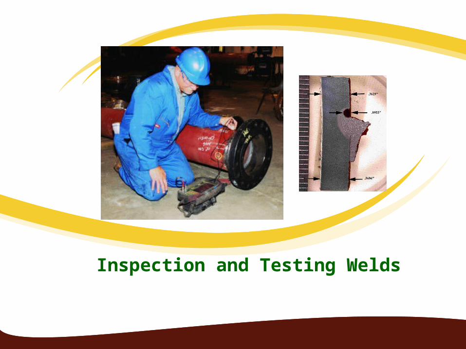
Inspection and Testing Welds
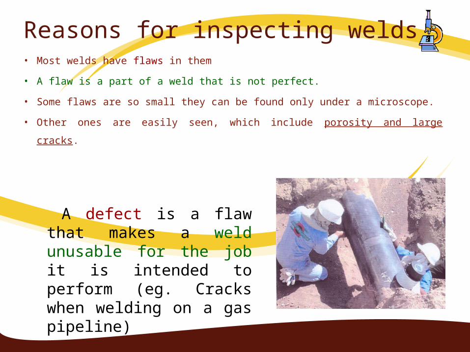
Reasons for inspecting welds• Most welds have flaws in them
• A flaw is a part of a weld that is not perfect.
• Some flaws are so small they can be found only under a microscope.
• Other ones are easily seen, which include porosity and large cracks.
A defect is a flaw that makes a weld unusable for the job it is intended to perform (eg. Cracks when welding on a gas pipeline)
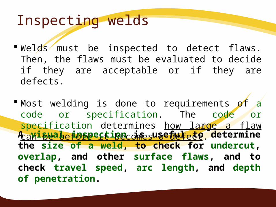
Inspecting welds
Welds must be inspected to detect flaws. Then, the flaws must be evaluated to decide if they are acceptable or if they are defects.
Most welding is done to requirements of a code or specification. The code or specification determines how large a flaw can be before it becomes a defect.
A visual inspection is useful to determine the size of a weld, to check for undercut, overlap, and other surface flaws, and to check travel speed, arc length, and depth of penetration.
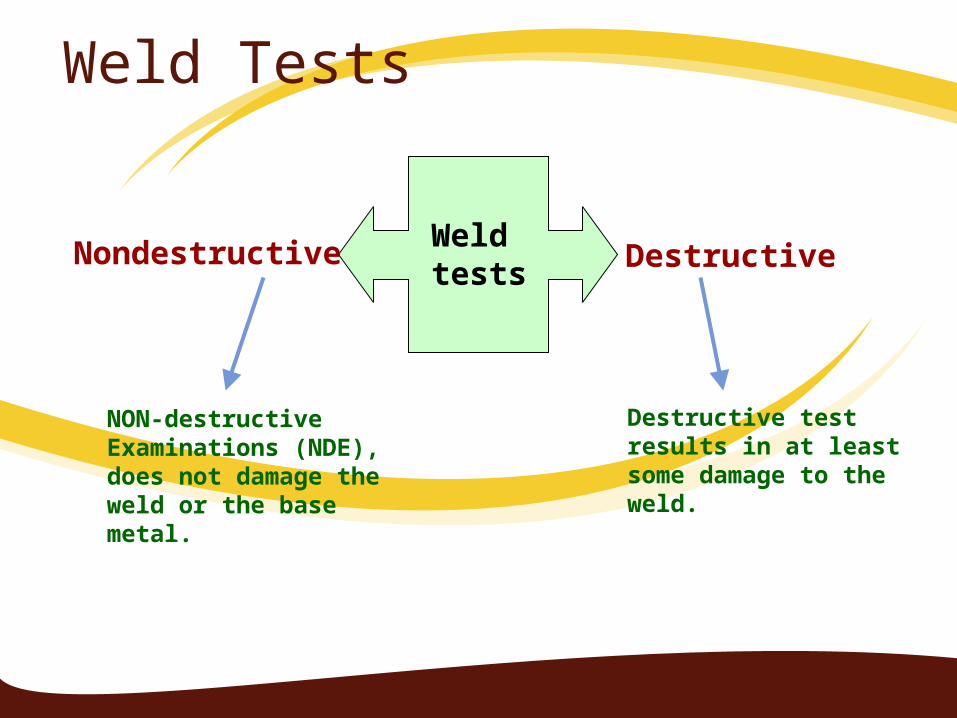
Weld Tests
Weld tests
Nondestructive Destructive
NON-destructive Examinations (NDE), does not damage the weld or the base metal.
Destructive test results in at least some damage to the weld.
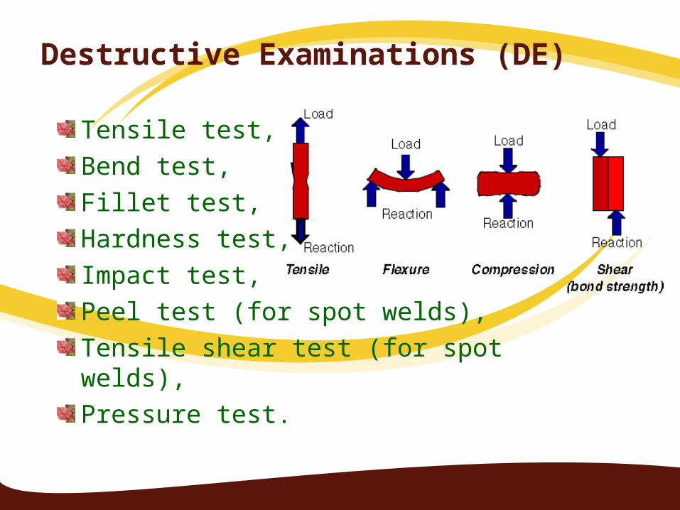
Destructive Examinations (DE)
Tensile test,Bend test,Fillet test,Hardness test,Impact test,Peel test (for spot welds),Tensile shear test (for spot welds),Pressure test.
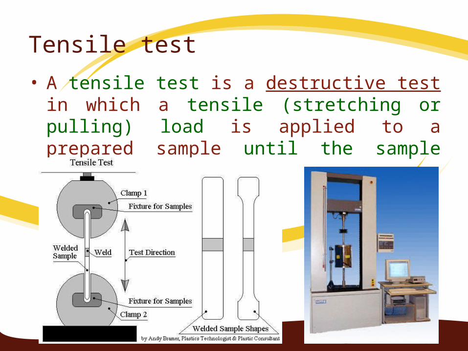
Tensile test• A tensile test is a destructive test in which a tensile
(stretching or pulling) load is applied to a prepared sample until the sample breaks.
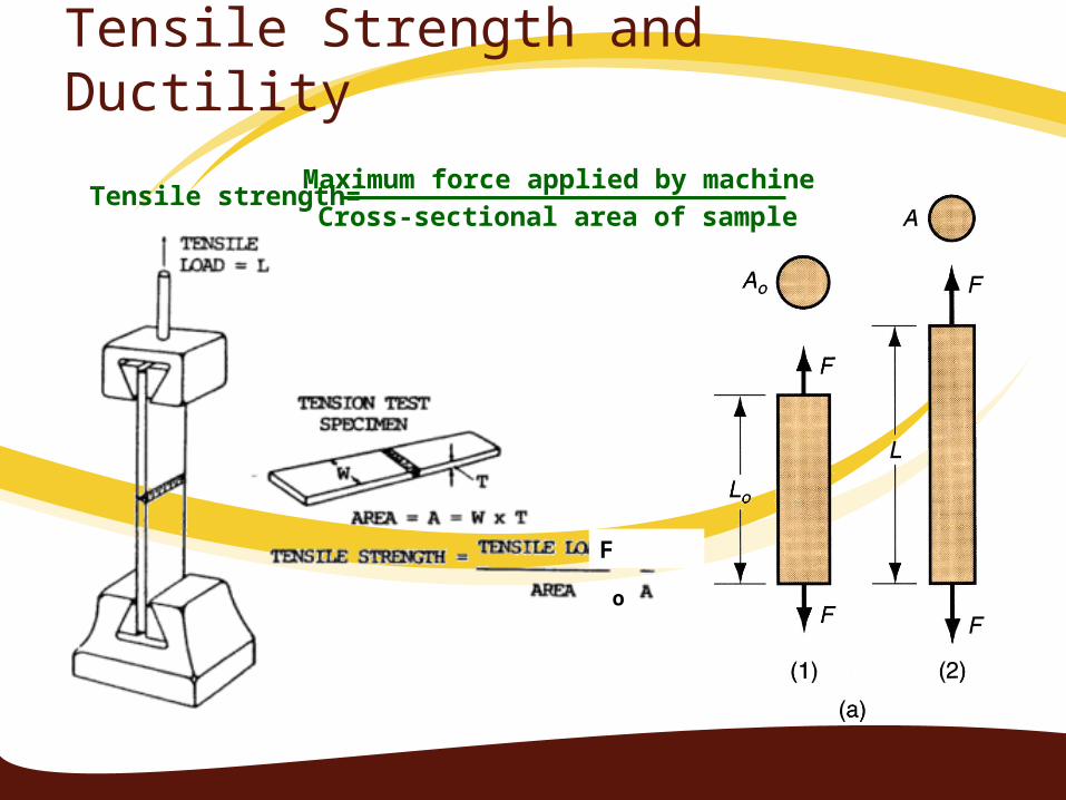
Tensile Strength and Ductility
Tensile strength=Maximum force applied by machine
Cross-sectional area of sample
F
o
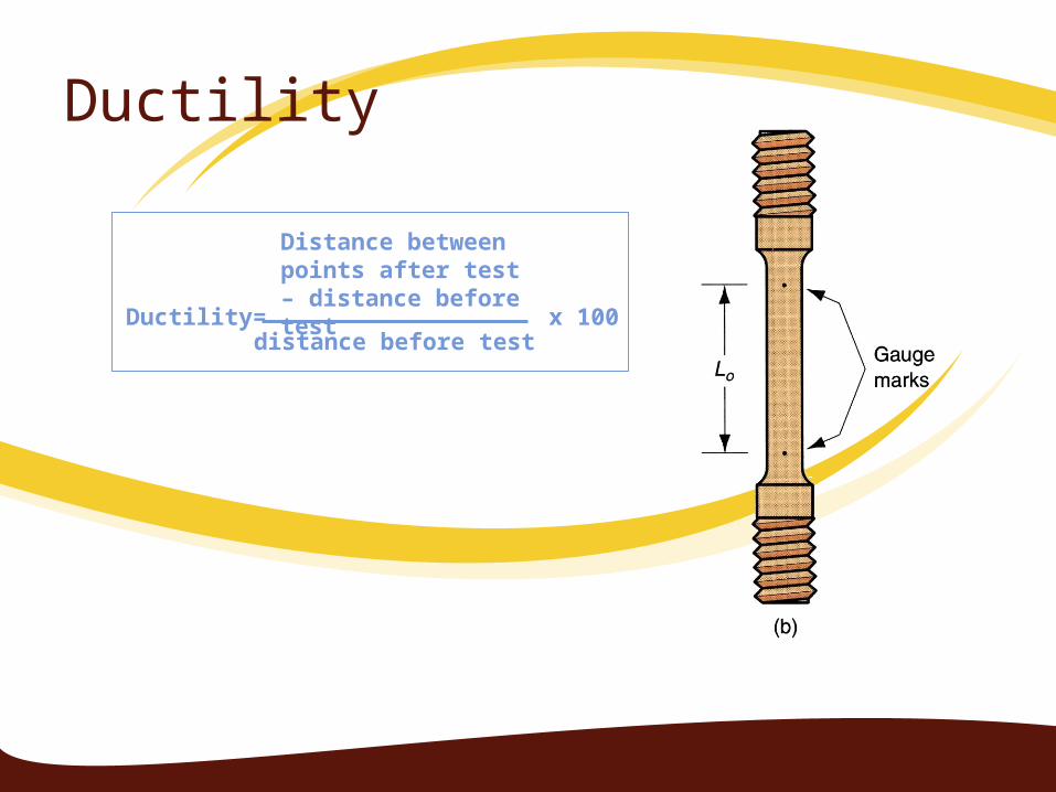
Ductility
Ductility= x 100
Distance between points after test – distance before test
distance before test
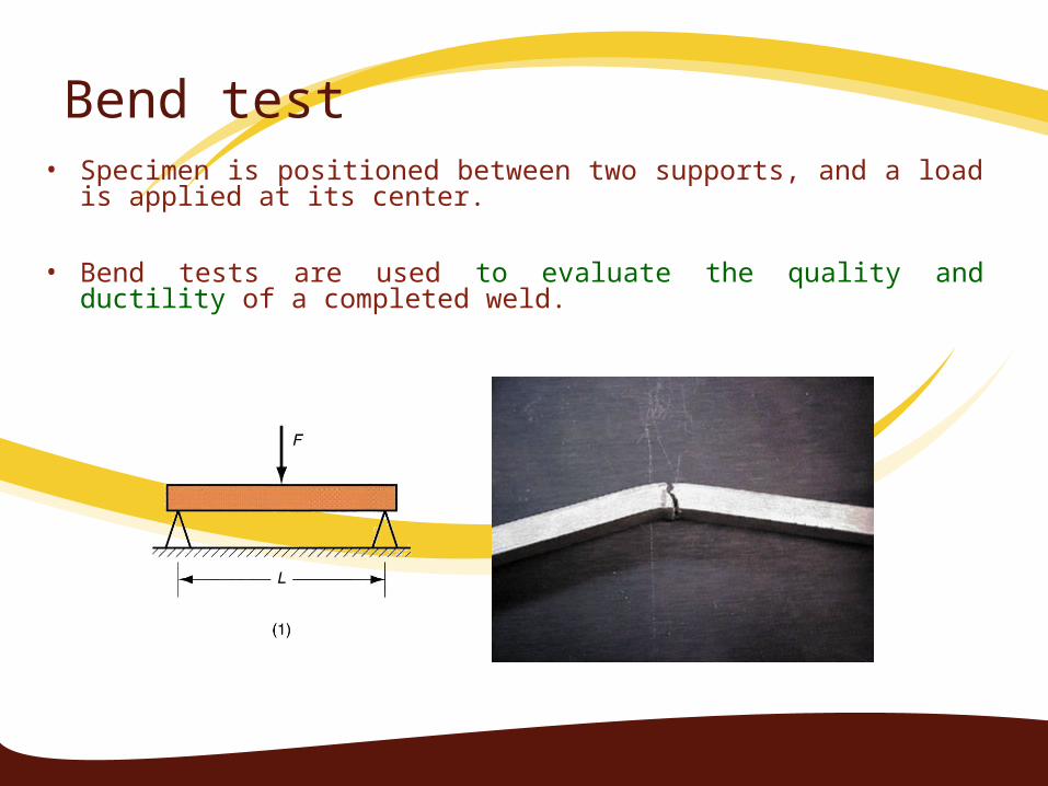
Bend test• Specimen is positioned between two supports, and a load is
applied at its center.
• Bend tests are used to evaluate the quality and ductility of a completed weld.
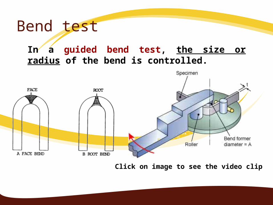
Bend testIn a guided bend test, the size or radius of the bend is controlled.
Click on image to see the video clip

Bend testIn a free bend test, the sample is placed into a large, strong vise and struck with a hammer until it bends to a 90˚ angle. It is then hammered in the opposite direction to a 90˚ angle. This back and forth bending continues until the weld sample breaks.
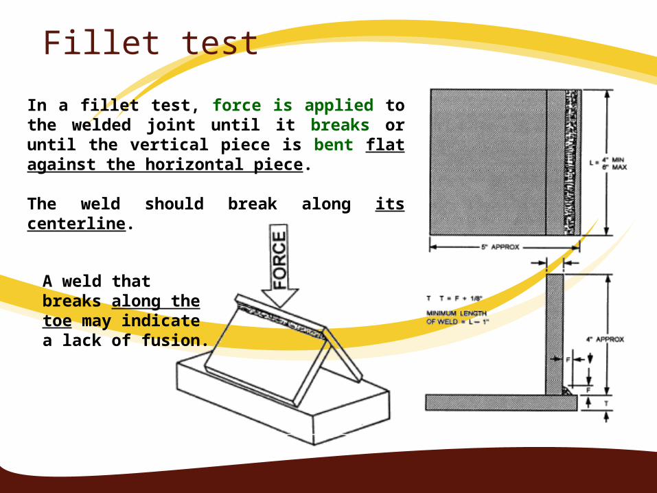
Fillet test
In a fillet test, force is applied to the welded joint until it breaks or until the vertical piece is bent flat against the horizontal piece.
The weld should break along its centerline.
A weld that breaks along the toe may indicate a lack of fusion.
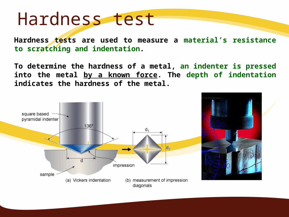
Hardness testHardness tests are used to measure a material’s resistance to scratching and indentation.
To determine the hardness of a metal, an indenter is pressed into the metal by a known force. The depth of indentation indicates the hardness of the metal.
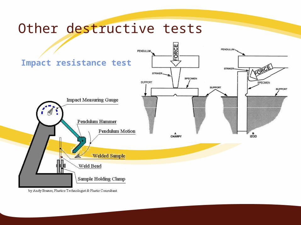
Other destructive tests
Impact resistance test
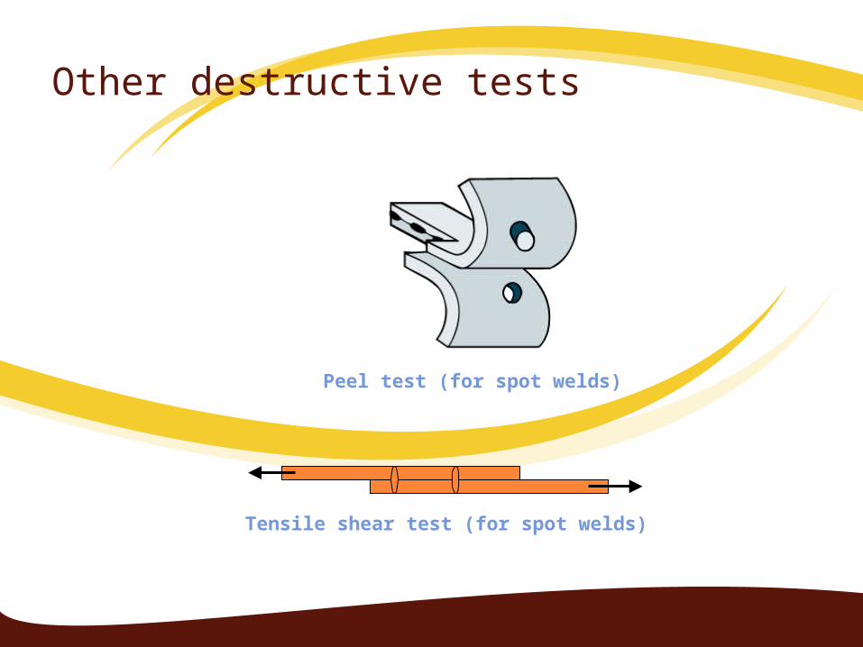
Other destructive tests
Peel test (for spot welds)
Tensile shear test (for spot welds)
INTRODUCTION TO NON DESTRUCTIVE TESTING
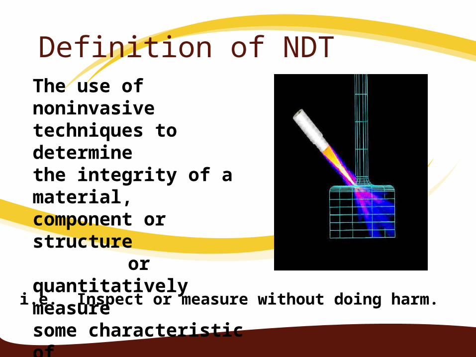
The use of noninvasive techniques to determine the integrity of a material, component or structure
or quantitatively measuresome characteristic ofan object.
i.e. Inspect or measure without doing harm.
Definition of NDT
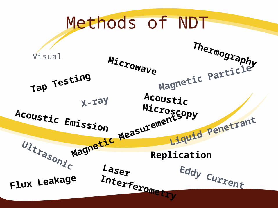
Methods of NDT
Visual
Liquid Penetrant
Magnetic Particle
Eddy Current
Ultrasonic
X-ray
Microwave
Acoustic Emission
Thermography
Laser Interferometry
Replication
Flux Leakage
Acoustic Microscopy
Magnetic Measurements
Tap Testing
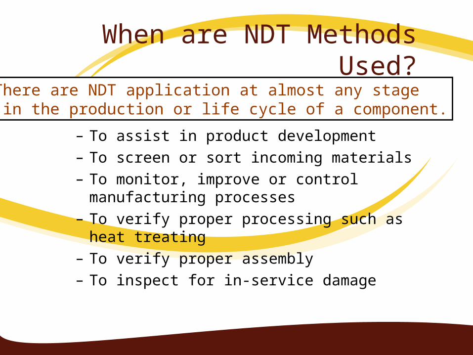
When are NDT Methods Used?
– To assist in product development – To screen or sort incoming materials– To monitor, improve or control manufacturing
processes– To verify proper processing such as heat treating– To verify proper assembly– To inspect for in-service damage
There are NDT application at almost any stage in the production or life cycle of a component.
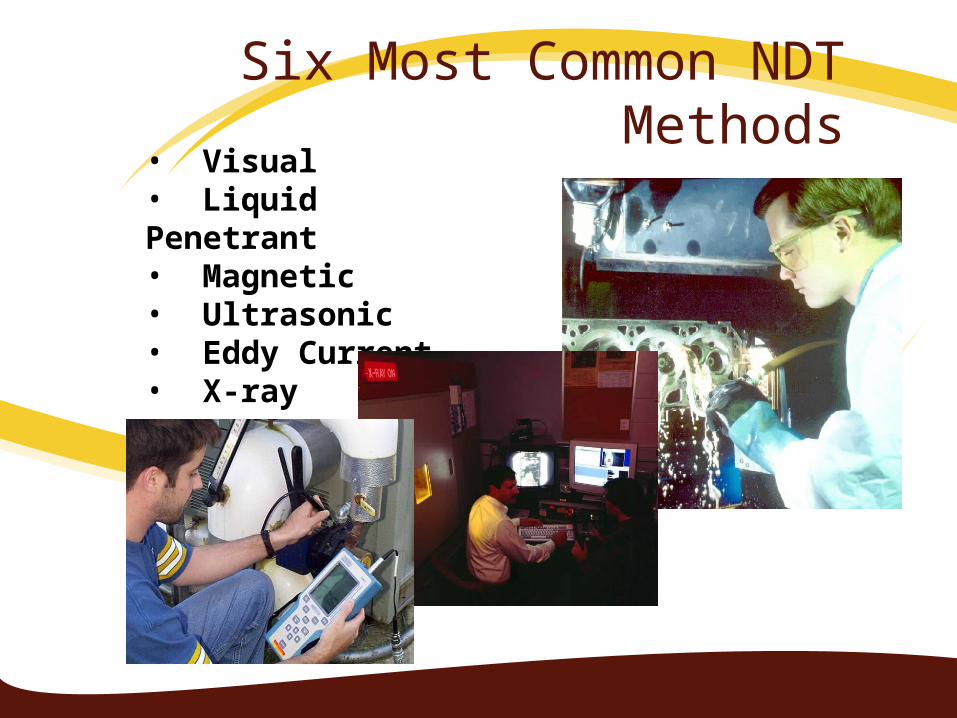
Six Most Common NDT Methods• Visual• Liquid Penetrant • Magnetic • Ultrasonic• Eddy Current• X-ray
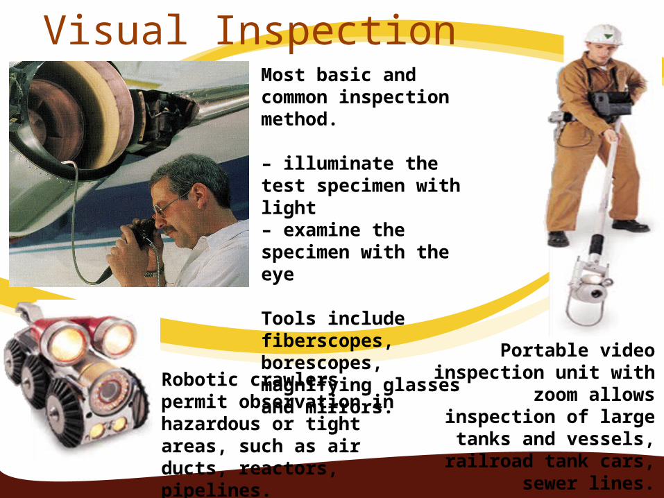
Most basic and common inspection method.
– illuminate the test specimen with light– examine the specimen with the eye
Tools include fiberscopes, borescopes, magnifying glasses and mirrors.
Robotic crawlers permit observation in hazardous or tight areas, such as air ducts, reactors, pipelines.
Portable video inspection unit with zoom allows
inspection of large tanks and vessels, railroad tank
cars, sewer lines.
Visual Inspection
VISUAL INSPECTION EQUIPMENT:
VISUAL INSPECTION EQUIPMENT:
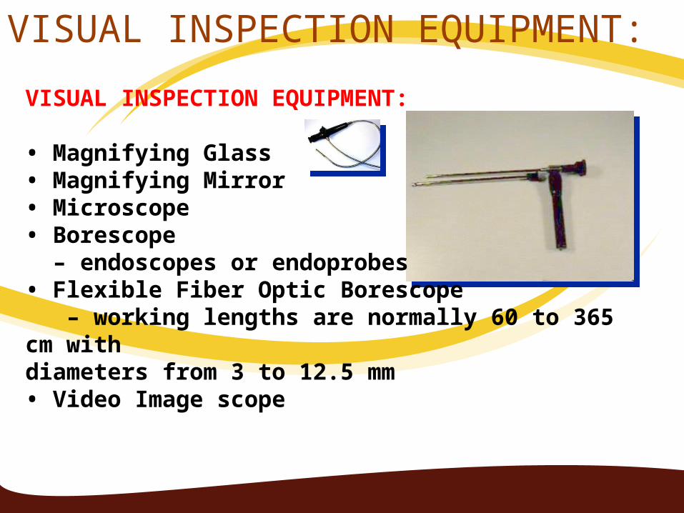
• Magnifying Glass• Magnifying Mirror• Microscope• Borescope – endoscopes or endoprobes• Flexible Fiber Optic Borescope – working lengths are normally 60 to 365 cm withdiameters from 3 to 12.5 mm• Video Image scope
APPLICATIONS OF VISUAL INSPECTIONVisual examination are carried out before welding,
during welding and after welding.Before Welding:
For detecting dents, burrs, scales, seams or laps and also dirt grease rust and mill scale on the fusion faces and edge preparation.
During Welding: For checking the geometry of the edge and joint preparation i.e. root face, bevel and included angles etc.
After Welding: For cleaning the weld and to remove spatter, scale and slag
Welding Defect To Be Inspected By Visual Inspection By visual inspection finished welds are
inspected for following external defects:1. Appearance of ripples on the weld2. Lack of fusion at the root of the butt weld3. Overlaps4. Undercuts5. Unfilled craters6. External cracks7. Improper size and shape of beads8. Misalignment9. Surface porosity10.Excessive reinforcement and spatter11.Arc strikes
Advantages And Disadvantages of Visual InspectionAdvantages:1. Economical2. Expedient3. Requires relatively little training4. Relatively little and less costly equipment5. Versatile6. Most widely used of all the nondestructive tests.7. Simple, easy to apply, quickly carried out and
usually low in cost.Disadvantages:1. Limited to external defects or surface conditions
only2. Limited to the visual acuity of the inspector
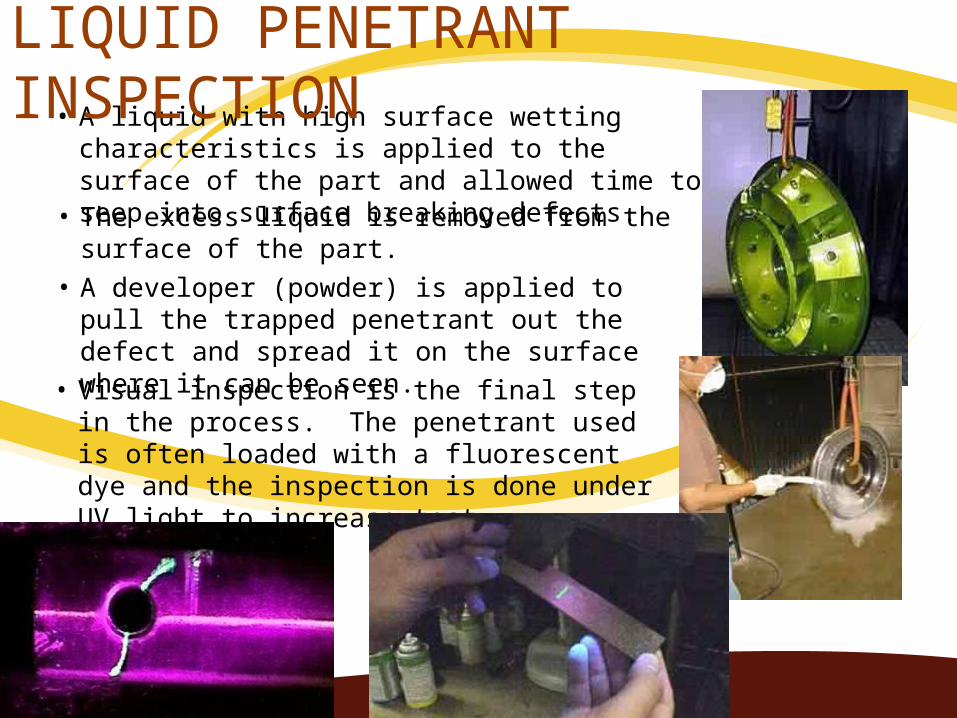
• A liquid with high surface wetting characteristics is applied to the surface of the part and allowed time to seep into surface breaking defects.
• The excess liquid is removed from the surface of the part.
• A developer (powder) is applied to pull the trapped penetrant out the defect and spread it on the surface where it can be seen.
• Visual inspection is the final step in the process. The penetrant used is often loaded with a fluorescent dye and the inspection is done under UV light to increase test sensitivity.
LIQUID PENETRANT INSPECTION
Introduction of liquid penetrant testing
LPT is based on the ability of a penetrating liquid to wet the surface opening of a weld defect and to be drawn into it.
LPT is used to detect the surface opening likes cracks, surface porosity etc in stainless steel, Al, magnesium, brass and other non porous metals.
LPT is of two types:1. Dye penetrant testing ( Uses red colour liquid
penetrant such as Dy check, Met L check)
2. Fluorescent penetrant testing( Uses Fluorescent liquid such as Zyglo penetrex)
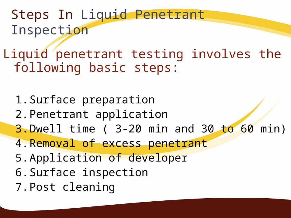
Steps In Liquid Penetrant Inspection
Liquid penetrant testing involves the following basic steps:
1. Surface preparation2. Penetrant application3. Dwell time ( 3-20 min and 30 to 60 min)4. Removal of excess penetrant5. Application of developer6. Surface inspection7. Post cleaning
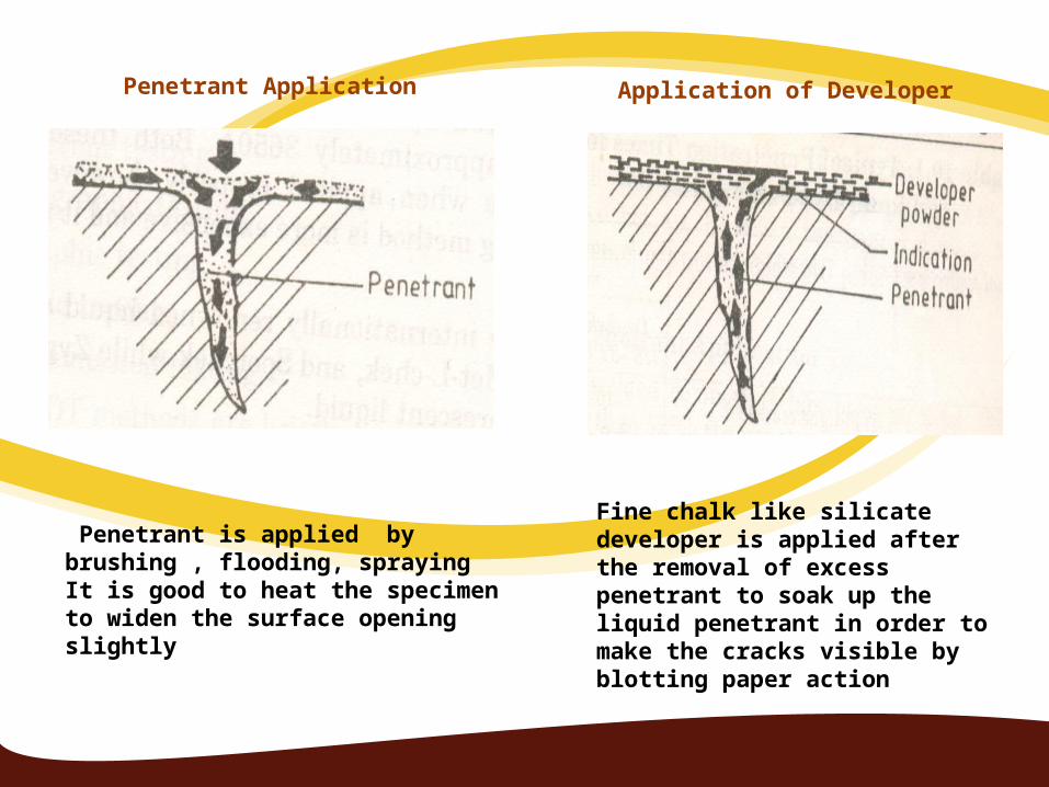
Penetrant is applied by brushing , flooding, sprayingIt is good to heat the specimen to widen the surface opening slightly
Fine chalk like silicate developer is applied after the removal of excess penetrant to soak up the liquid penetrant in order to make the cracks visible by blotting paper action
Penetrant Application Application of Developer
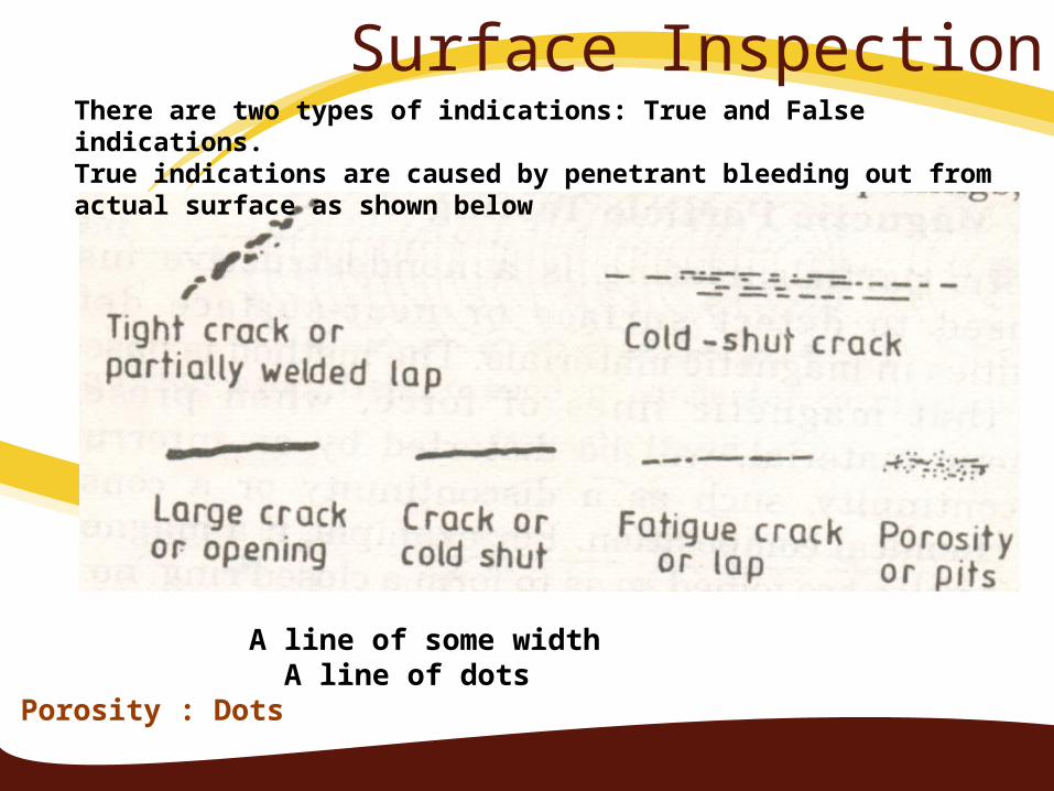
Surface InspectionThere are two types of indications: True and False indications. True indications are caused by penetrant bleeding out from actual surface as shown below
Large crack: A line of some width Fatigue crack: A line of dots Porosity : Dots
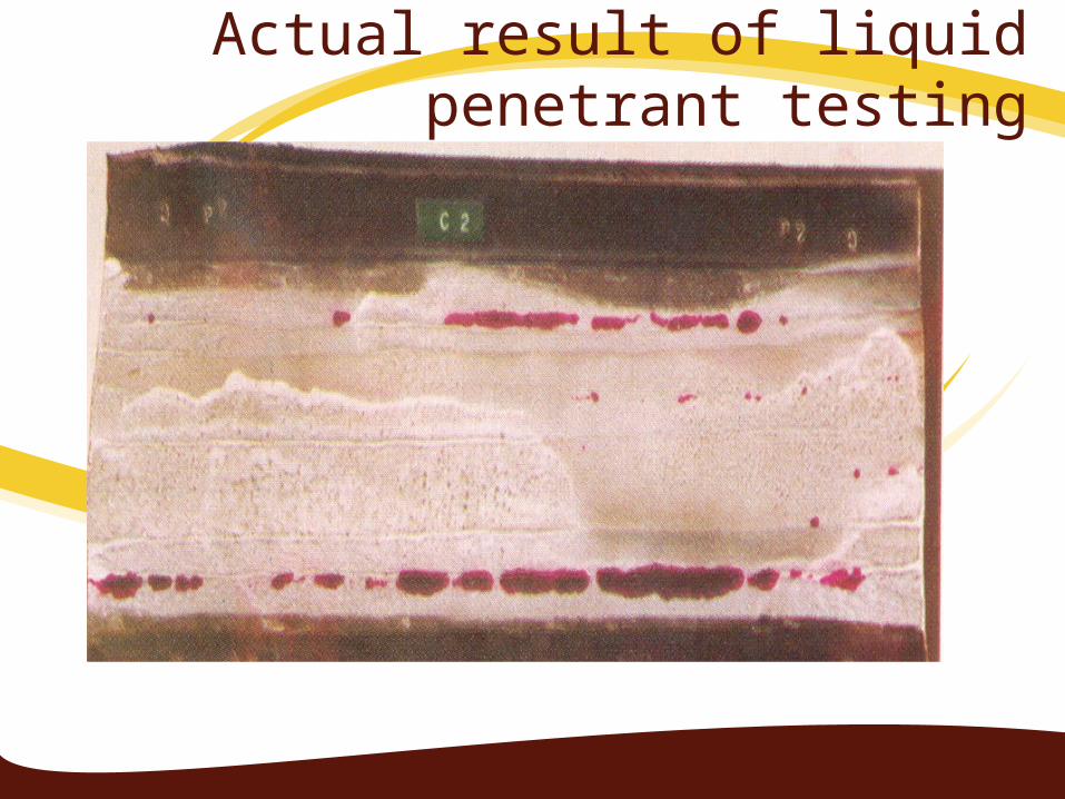
Actual result of liquid penetrant testing
ADVANTAGES OF LIQUID PENETRANT INSPECTION
1.May be used on all non porous materials.2.Versatile and portable3.Relatively inexpensive4.Expedient inspection results5.Result are easily interpreted6.Requires no electrical energy except for light
source7.Indications may be further examined visually
APPLICATIONS OF LIQUID PENETRANT INSPECTION
1. Used to detect weld discontinuities open to surface i.e. Cracks, porosity ,seams
2. Used on nonporous materials 3. Can be applied to welds, tubing, brazing, castings,
billets, forgings, aluminium parts, turbine blades and disks, gears
LIMITATIONS LIQUID PENETRANT INSPECTION
1. Surface film such as coatings, scale hide rejectable defects2. Bleed out from porous surface can also mask indications3. Part must be cleaned before and after inspection4. Defects must be surface breaking 5. Decontamination & precleaning of test surface may be
needed 6. Vapour hazard 7. It is difficult to find very tight and shallow defects8. Depth of flaw not indicated

Magnetic Particle Testing• MPT is used to detect surface or near surface defects in magnetic
materials.• MPT is based on the principle that magnetic lines of force, when present
in a ferromagnetic material, will be distorted by an interruption in material continuity .
• If a magnet is bent and the two poles are joined so as to form a closed ring, no external poles exist and hence it will have no attraction for magnetic material.
• Thus as long as part to be inspected is free of cracks, magnetic particle will not be attracted.
• When a crack or other discontinuity is present , north and south magnetic are set up at edges of the discontinuity
• The magnetic particles will be attracted to the poles which are the edges of the crack and will cluster to form an indication directly over the discontinuity
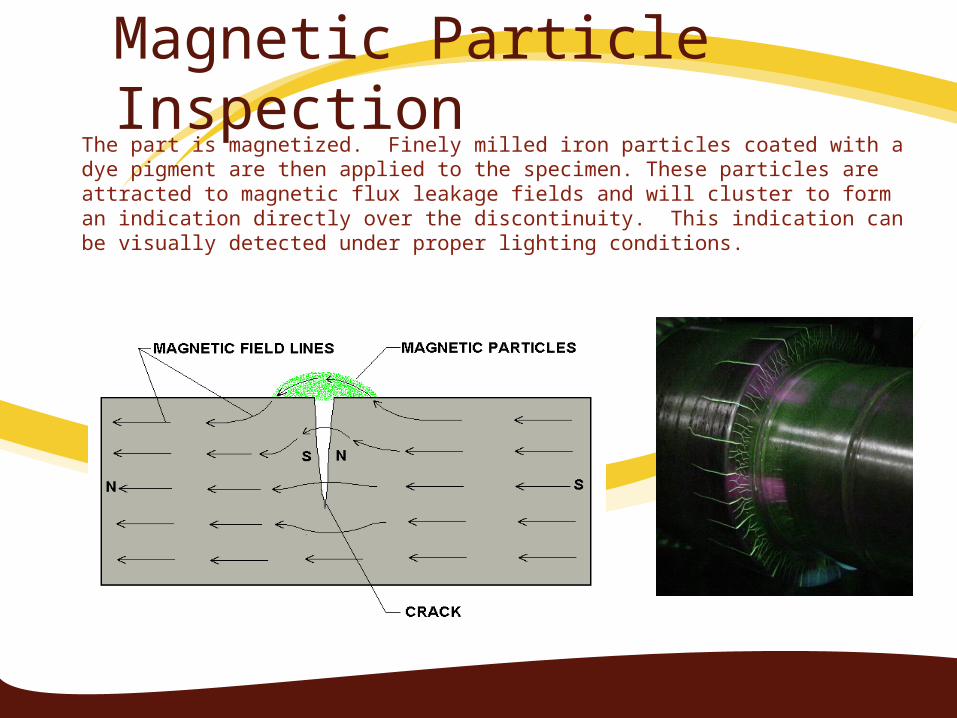
Magnetic Particle InspectionThe part is magnetized. Finely milled iron particles coated with a dye pigment are then applied to the specimen. These particles are attracted to magnetic flux leakage fields and will cluster to form an indication directly over the discontinuity. This indication can be visually detected under proper lighting conditions.
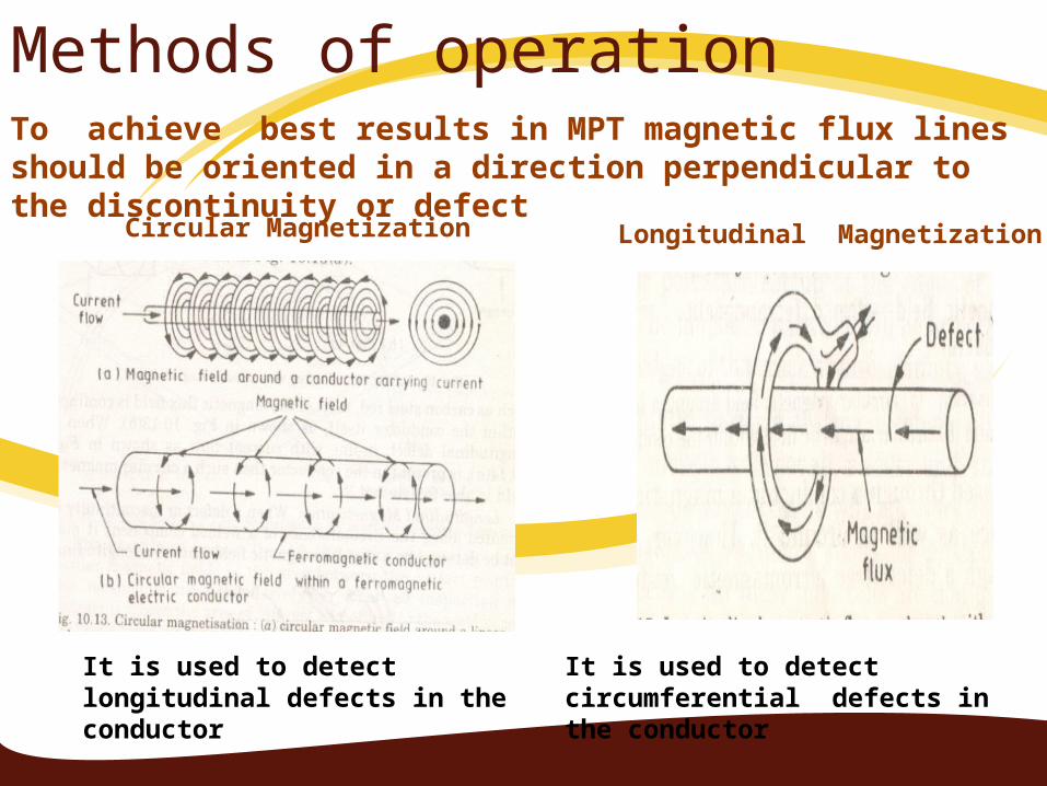
Methods of operation
Circular Magnetization Longitudinal Magnetization
It is used to detect longitudinal defects in the conductor
It is used to detect circumferential defects in the conductor
To achieve best results in MPT magnetic flux lines should be oriented in a direction perpendicular to the discontinuity or defect
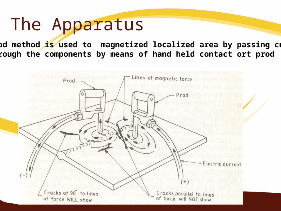
The ApparatusProd method is used to magnetized localized area by passing currentThrough the components by means of hand held contact ort prod
Applications of MPTMPT is used to detect following defects:
1. Surface and sub surface cracks2. Incomplete fusion3. Slag inclusion4. Porosity5. Inadequate joint penetration6. Lamination7. Seams undercutIn magnetic steels, cast irons, nickel and cobalt
alloys

Magnetic Particle Crack Indications

Advantages & Disadvantages of MPT
Disadvantages:
1. limited to only ferromagnetic materials2. Parts must be cleaned before and after
inspection3. Need to demagnetize parts after inspection
Advantages:1. Inexpensive and portable apparatus2. Reliable results3. Can detect subsurface defects

Eddy Current TestingEddy current testing is particularly well suited for detecting surface cracks but can also be used to make electrical conductivity and coating thickness measurements. Here a small surface probe is scanned over the part surface in an attempt to detect a crack.
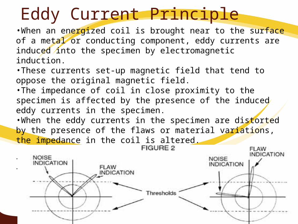
Eddy Current Principle•When an energized coil is brought near to the surface of a metal or conducting component, eddy currents are induced into the specimen by electromagnetic induction. •These currents set-up magnetic field that tend to oppose the original magnetic field.•The impedance of coil in close proximity to the specimen is affected by the presence of the induced eddy currents in the specimen. •When the eddy currents in the specimen are distorted by the presence of the flaws or material variations, the impedance in the coil is altered. •This change is measured and displayed in a manner that indicatesthe type of flaw or material condition.
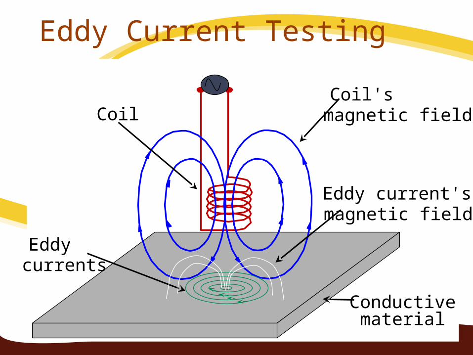
Conductive material
CoilCoil's magnetic field
Eddy currents
Eddy current's magnetic field
Eddy Current Testing
Advantages & Disadvantages of
Advantages & Disadvantages of ECT
e
Advantages:1.Relatively expedient2.Low cost3.Automation is possible for symmetrical parts4.No couplant is required5.Probe does not have to be in intimate contact with the test piece.
l
Disadvantages:1.Limited to conductive materials2.Shallow depth of penetration3.Some indications may be masked by part geometry due to sensitivity variation4.Reference standard are required
Applications of ECTFollowing are the main applications of ECT:1.Weld discontinuities open to the surface i.e. cracks, porosity etc 2.Sub surface defects3.Alloy content4.Heat treatment variation5.Wall thickness6.Range from crack detection, to the rapid sorting of small components for either flaws, size variations, or material variation.7.Commonly used in aerospace, automotive, marine, and manufacturing industries.
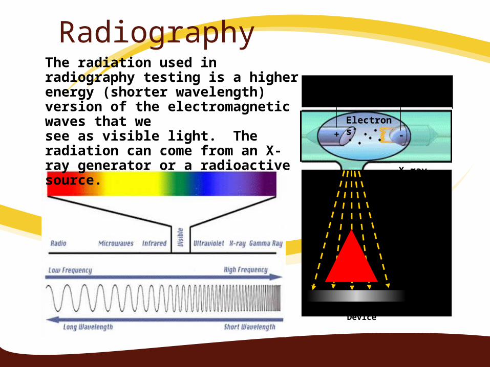
RadiographyThe radiation used in radiography testing is a higher energy (shorter wavelength) version of the electromagnetic waves that we see as visible light. The radiation can come from an X-ray generator or a radioactive source.
High Electrical Potential
Electrons
-+
X-ray Generator or Radioactive Source Creates
Radiation
Exposure Recording Device
Radiation Penetrate the Sample
Principle of RadiographyWhen a test piece or a welded joint is exposed to a
penetrating radiation like X rays or γ rays variations in amount of radiation transmitted through it depends upon:
– The relative densities of the metal and any inclusion– Thru thickness variation
Non metallic inclusions, pores, aligned cracks and other defects results in less or more radiation reaching the recording film.
The variations in transmitted radiation produce optically contrasting areas on the recording film
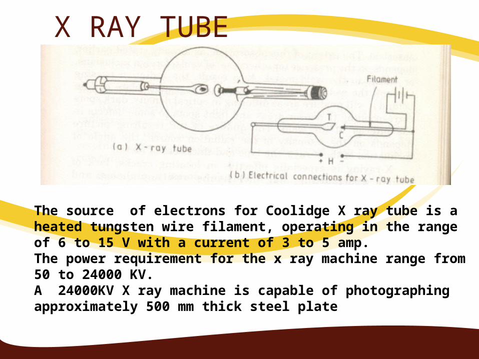
X RAY TUBE
The source of electrons for Coolidge X ray tube is a heated tungsten wire filament, operating in the range of 6 to 15 V with a current of 3 to 5 amp.The power requirement for the x ray machine range from 50 to 24000 KV.A 24000KV X ray machine is capable of photographing approximately 500 mm thick steel plate

Film Radiography
Top view of developed film
X-ray film
The part is placed between the radiation source and a piece of film. The part will stop some of the radiation. Thicker and more dense area will stop more of the radiation.
= more exposure
= less exposure
The film darkness (density) will vary with the amount of radiation reaching the film through the test object.
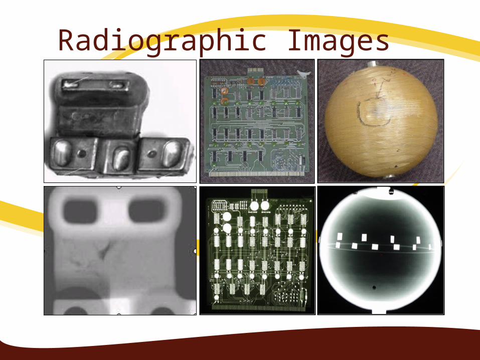
Radiographic Images
Advantages & Disadvantages of Radiography
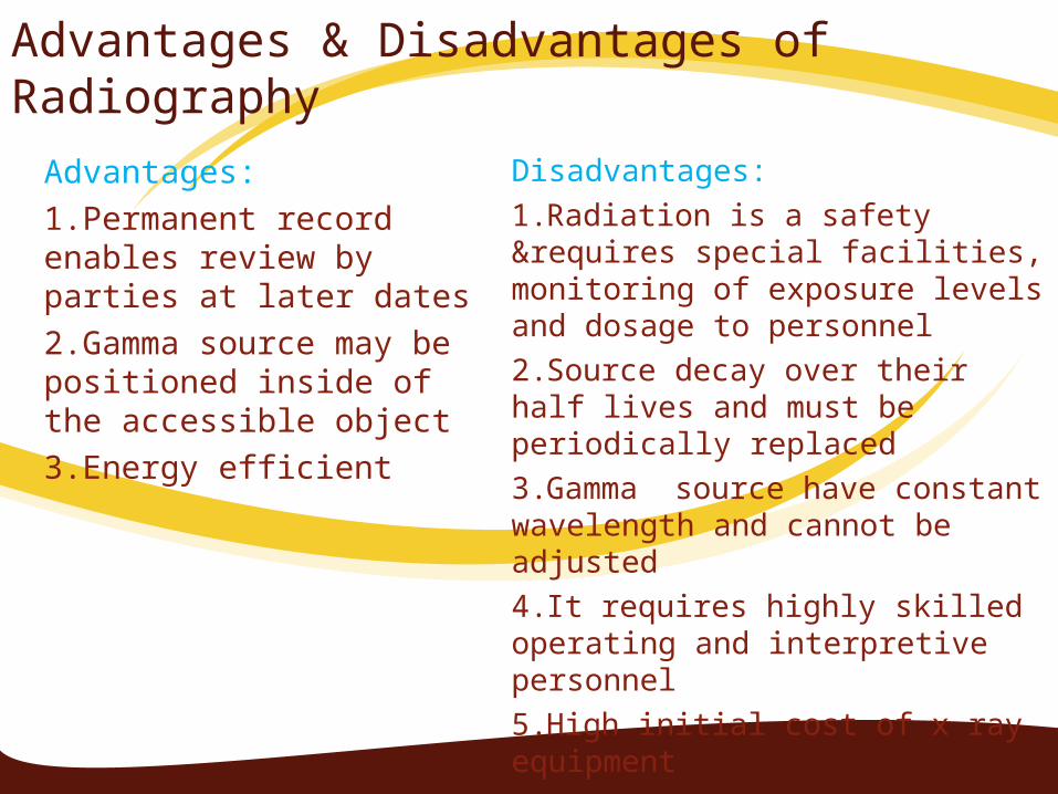
Advantages:1.Permanent record enables review by parties at later dates2.Gamma source may be positioned inside of the accessible object3.Energy efficient
Disadvantages:1.Radiation is a safety &requires special facilities, monitoring of exposure levels and dosage to personnel2.Source decay over their half lives and must be periodically replaced3.Gamma source have constant wavelength and cannot be adjusted4.It requires highly skilled operating and interpretive personnel5.High initial cost of x ray equipment
Applications of RadiographyIt is used to detect most of the sub surface weld defects such as 1.cracks, 2.porosity,3. lack of fusion, 4.incomplete penetration, 5.Slag and corrosion entrapment6. wall thickness7. dimensional evaluations
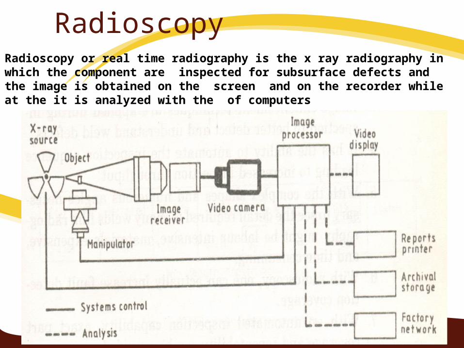
RadioscopyRadioscopy or real time radiography is the x ray radiography in which the component are inspected for subsurface defects and the image is obtained on the screen and on the recorder while at the it is analyzed with the of computers

High frequency (20000 Hz) sound waves are introduced into a material and they are reflected back from surfaces or flaws.
Reflected sound energy is displayed versus time, and inspector can visualize a cross section of the specimen showing the depth of features that reflect sound.
f
plate
crack
0 2 4 6 8 10
initial pulse
crack echo
back surface echo
Oscilloscope, or flaw detector screen
Ultrasonic Inspection (Pulse-Echo)
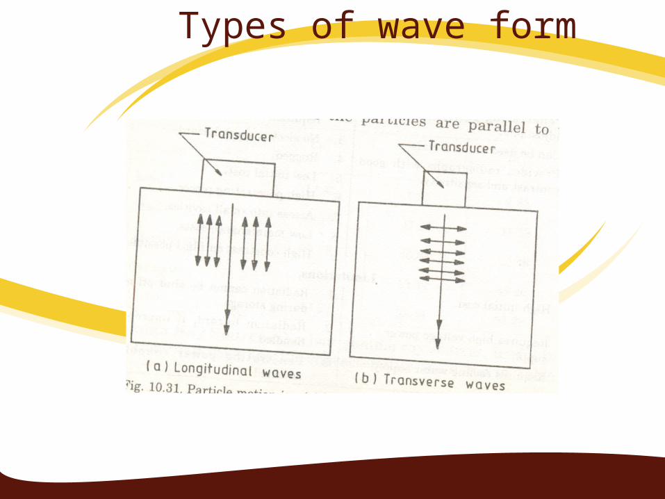
Types of wave form
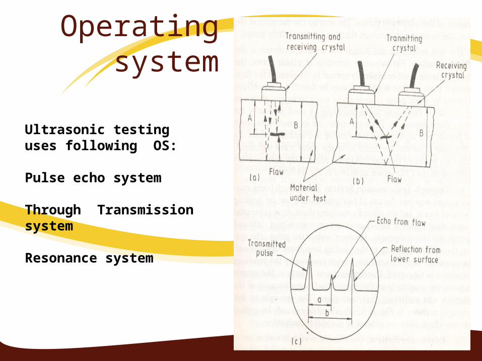
Operating system
Ultrasonic testing uses following OS:
Pulse echo system
Through Transmission system
Resonance system
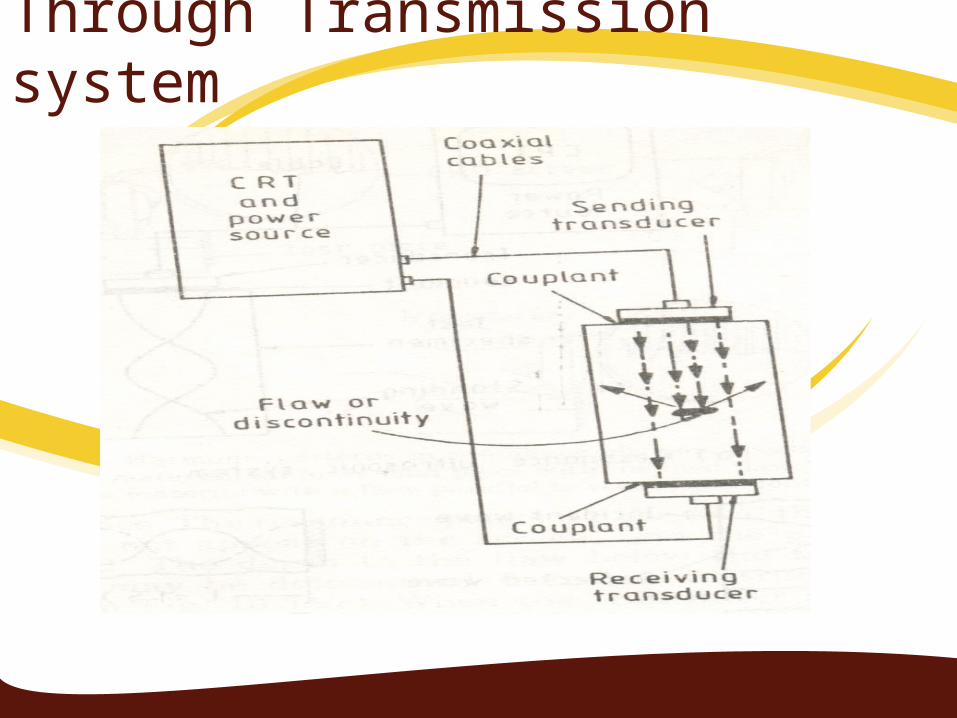
Through Transmission system
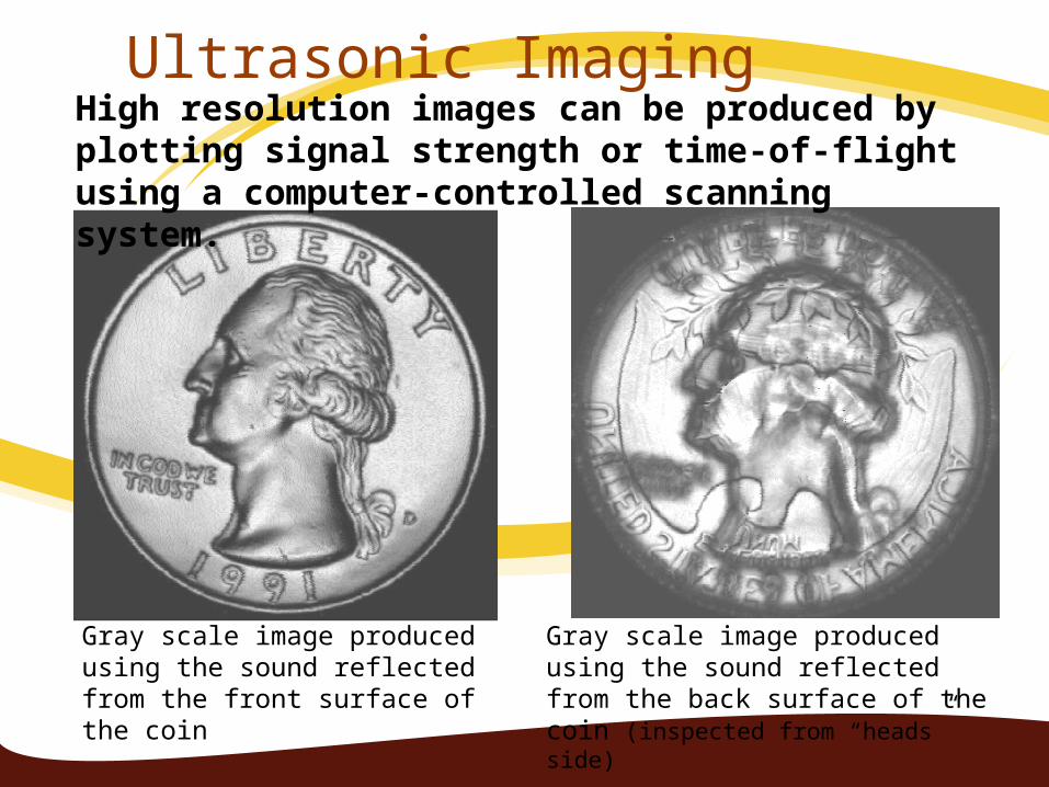
Ultrasonic Imaging
Gray scale image produced using the sound reflected from the front surface of the coin
Gray scale image produced using the sound reflected from the back surface of the coin (inspected from “heads” side)
High resolution images can be produced by plotting signal strength or time-of-flight using a computer-controlled scanning system.

Common Application of NDT
Inspection of Raw ProductsInspection Following Secondary
ProcessingIn-Services Damage Inspection
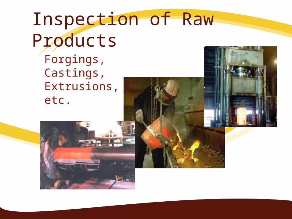
Inspection of Raw ProductsForgings,Castings,Extrusions,etc.

Inspection Following Secondary Processing
MachiningWeldingGrindingHeat treatingPlatingetc.
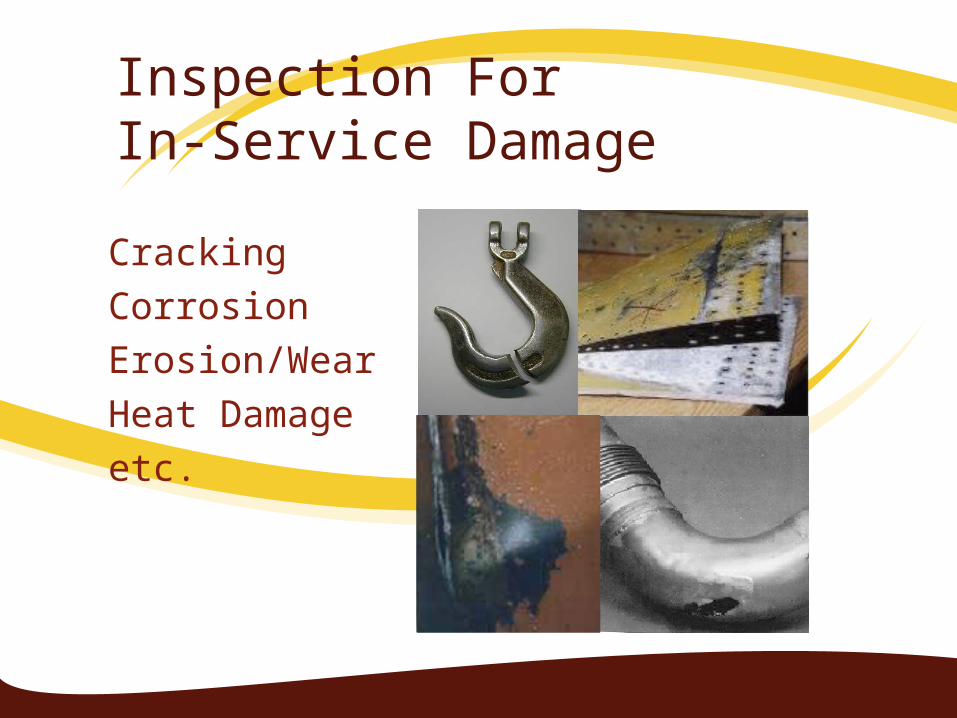
Inspection For In-Service Damage
CrackingCorrosionErosion/WearHeat Damageetc.
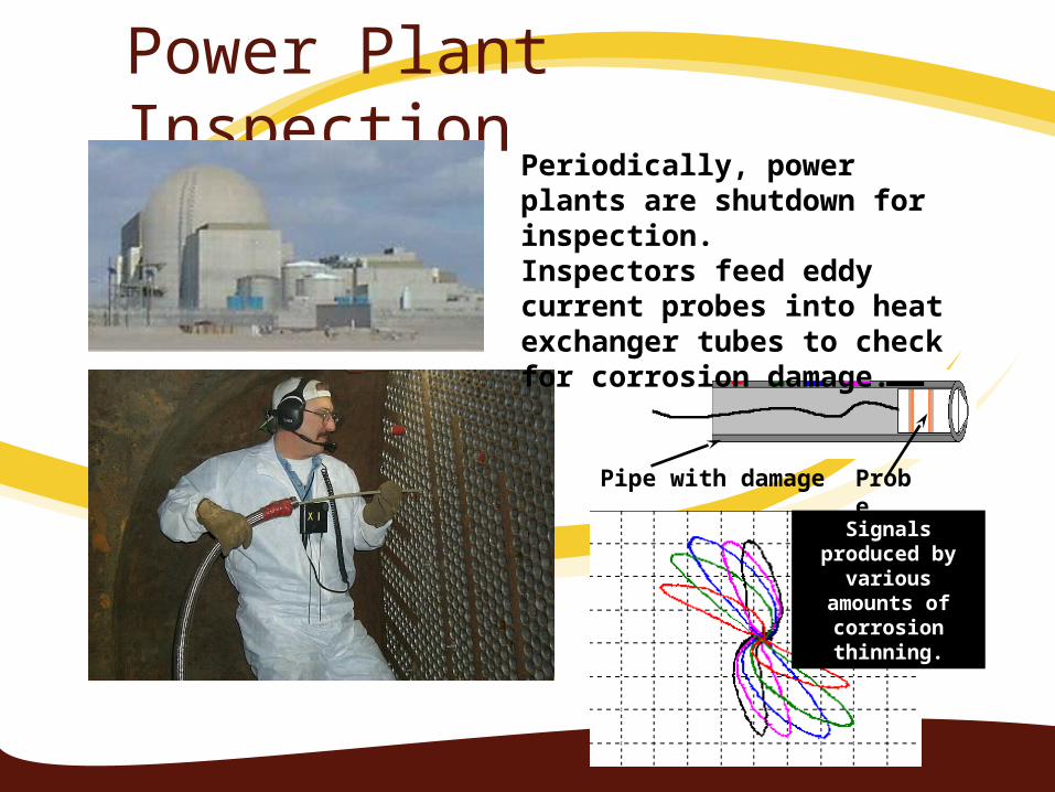
Power Plant Inspection
Probe
Signals produced by
various amounts of corrosion
thinning.
Periodically, power plants are shutdown for inspection. Inspectors feed eddy current probes into heat exchanger tubes to check for corrosion damage.
Pipe with damage
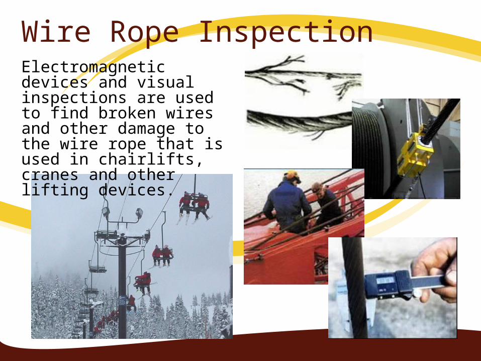
Wire Rope InspectionElectromagnetic devices and visual inspections are used to find broken wires and other damage to the wire rope that is used in chairlifts, cranes and other lifting devices.
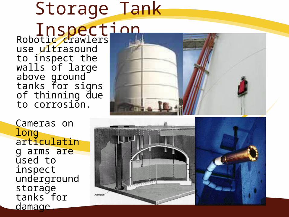
Storage Tank InspectionRobotic crawlers use ultrasound to inspect the walls of large above ground tanks for signs of thinning due to corrosion.
Cameras on long articulating arms are used to inspect underground storage tanks for damage.
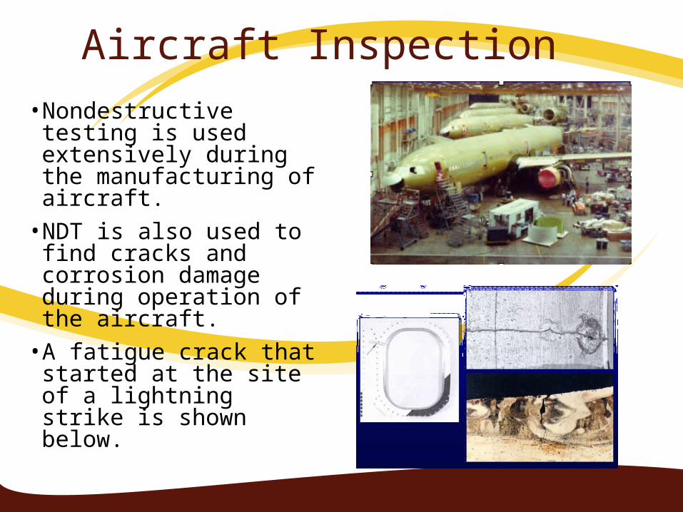
Aircraft Inspection• Nondestructive testing is
used extensively during the manufacturing of aircraft.
• NDT is also used to find cracks and corrosion damage during operation of the aircraft.
• A fatigue crack that started at the site of a lightning strike is shown below.
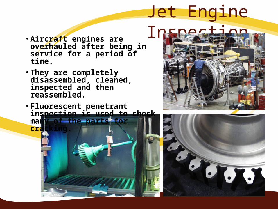
Jet Engine Inspection• Aircraft engines are overhauled
after being in service for a period of time.
• They are completely disassembled, cleaned, inspected and then reassembled.
• Fluorescent penetrant inspection is used to check many of the parts for cracking.
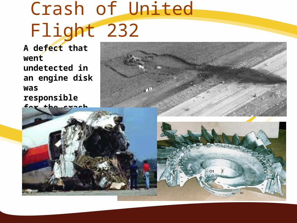
A defect that went undetected in an engine disk was responsible for the crash of United Flight 232.
Crash of United Flight 232
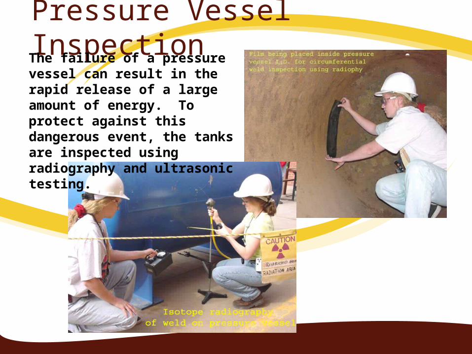
Pressure Vessel InspectionThe failure of a pressure vessel can result in the rapid release of a large amount of energy. To protect against this dangerous event, the tanks are inspected using radiography and ultrasonic testing.
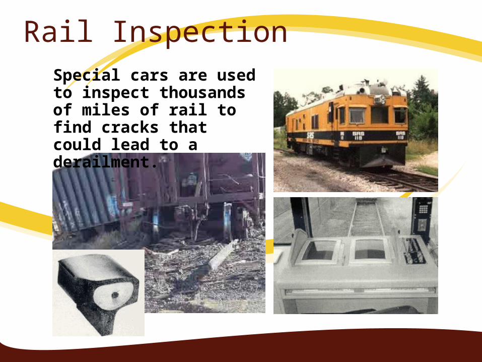
Rail InspectionSpecial cars are used to inspect thousands of miles of rail to find cracks that could lead to a derailment.
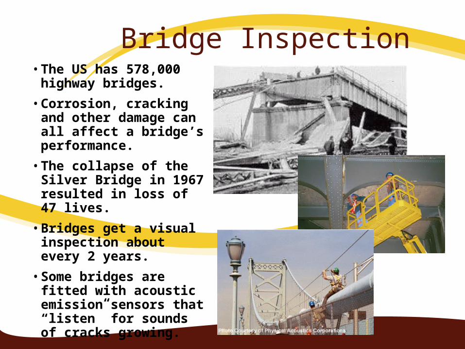
Bridge Inspection• The US has 578,000
highway bridges.
• Corrosion, cracking and other damage can all affect a bridge’s performance.
• The collapse of the Silver Bridge in 1967 resulted in loss of 47 lives.
• Bridges get a visual inspection about every 2 years.
• Some bridges are fitted with acoustic emission sensors that “listen” for sounds of cracks growing.
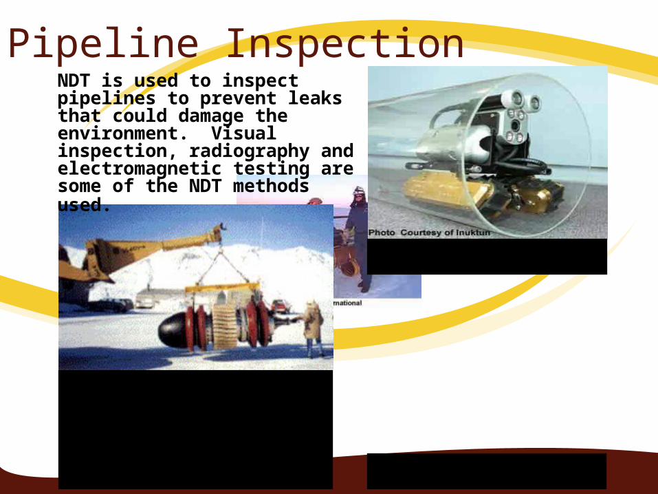
Pipeline InspectionNDT is used to inspect pipelines to prevent leaks that could damage the environment. Visual inspection, radiography and electromagnetic testing are some of the NDT methods used.
Remote visual inspection using a robotic crawler.
Radiography of weld joints.
Magnetic flux leakage inspection. This device, known as a pig, is placed in the pipeline and collects data on the condition of the pipe as it is pushed along by whatever is being transported.
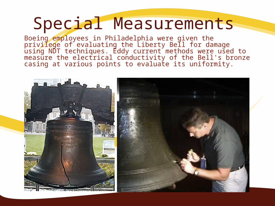
Special MeasurementsBoeing employees in Philadelphia were given the privilege of evaluating the Liberty Bell for damage using NDT techniques. Eddy current methods were used to measure the electrical conductivity of the Bell's bronze casing at various points to evaluate its uniformity.

T H KNA S